1
TECHNICAL & SERVICE MANUAL
Gas Heat Pump Air Conditioner
Type M2 Series
TROUBLESHOOTING
March 2008
Applicable Models : W MULTI
: 3WAY MULTI
: G POWER W MULTI
Reference No.SM7110015
◆◇◆ Applicable models ◆◇◆
< W MULTI >
SGP-EW120M2G2W
SGP-EW150M2G2W
SGP-EW190M2G2W
SGP-EW240M2G2W
< 3WAY MULTI >
SGP-EZ150M2G2
SGP-EZ190M2G2
SGP-EZ240M2G2
< G POWER W MULTI >
SGP-EGW190M2G2W
◆◇◆ Table of Contents ◆◇◆
1. Symptoms that are not malfunctions.......................................................................Ⅰ -1
2. Before troubleshooting (W MULTI series)................................................................Ⅱ -1
(1) W MULTI series system overview..................................................................... Ⅱ -1
(2) About backup operation during maintenance work....................................... Ⅱ -2
3. Malfunctions and Displays........................................................................................Ⅲ -1
(1) Malfunctions without any display.................................................................... Ⅲ -1
(2) Remote controller alarm display...................................................................... Ⅲ -2
4. Error Display and Troubleshooting..........................................................................Ⅳ -1
(1) Precautions before Troubleshooting............................................................... Ⅳ -1
(2) About the Error Detection Procedure.............................................................. Ⅳ -1
(3) Engine Start Standby........................................................................................ Ⅳ -1
(4) Troubleshooting................................................................................................ Ⅳ -2
A01
A02
A03
A04
A05
A06
A07
A08
A10
A11
A12
A14
A15
A16
A17
A19
A20
A21
A22
A23
A24
A25
A26
A27
A28
A29
A30
E01
E02
E03
E04
E05
E06
E07
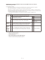
Engine Oil Pressure Error..........................................................................................Ⅳ -2
Engine Oil Error..........................................................................................................Ⅳ -4
Engine High-Revolution Error....................................................................................Ⅳ -5
Engine Low-Revolution Error.....................................................................................Ⅳ -6
Ignition Source Error..................................................................................................Ⅳ -7
Engine Start Failure...................................................................................................Ⅳ -9
Fuel Gas Valve Error................................................................................................Ⅳ -12
Engine Stall..............................................................................................................Ⅳ -13
Exhaust Gas Temperature High...............................................................................Ⅳ -14
Engine Oil Level Error..............................................................................................Ⅳ -15
Throttle (Step Motor) Error.......................................................................................Ⅳ -16
Engine Oil Pressure Switch Error.............................................................................Ⅳ -17
Starter Power Source Output Short Circuit...............................................................Ⅳ -18
Starter Lock..............................................................................................................Ⅳ -19
CT Error (Starter Current Detection Failure).............................................................Ⅳ -20
Low Coolant Temperature........................................................................................Ⅳ -21
High Coolant Temperature.......................................................................................Ⅳ -22
Coolant Level Error..................................................................................................Ⅳ -23
Coolant Pump Error.................................................................................................Ⅳ -24
Crankshaft Angle Sensor Error.................................................................................Ⅳ -25
Camshaft Angle Sensor Error...................................................................................Ⅳ -25
Clutch Error..............................................................................................................Ⅳ -26
Flameout Error.........................................................................................................Ⅳ -27
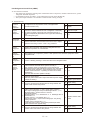
Catalyst Temperature Error (for only models with catalyst option)............................Ⅳ -28
Generator Error (for only G POWER W MULTI).......................................................Ⅳ -29
Converter Error (for only G POWER W MULTI)........................................................Ⅳ -30
Low Fuel Gas Pressure Error...................................................................................Ⅳ -31
Remote Controller Receive Failure..........................................................................Ⅳ -32
Remote Controller Transmission Failure..................................................................Ⅳ -33
Indoor Unit Receive Failure from Remote Controller (Central).................................Ⅳ -34
Indoor Unit Receive Failure from Outdoor Unit.........................................................Ⅳ -36
Indoor UnitTransmission Faiure to Outdoor Unit......................................................Ⅳ -38
Outdoor Unit Receive Failure from Indoor Unit.........................................................Ⅳ -39
Outdoor Unit Transmission Failure to Indoor Unit.....................................................Ⅳ -40
E08 Duplicated Indoor Unit Address Setting....................................................................Ⅳ -41
E09 Multiple Main Remoto Controller Units Set...............................................................Ⅳ -42
E11 Indoor Unit Receive Failure from Signal Output Board.............................................Ⅳ -43
E12 Automatic Address Setting Is in Progress
: Automatic Address Setting Start is Prohibited....................Ⅳ -44
E13 Indoor Unit Transmission Failure to Remoto controller.............................................Ⅳ -45
E15 Automatic Address Alarm (Too Few Units)...............................................................Ⅳ -46
E16 Automatic Address Alarm (Too Many Units).............................................................Ⅳ -47
E18 Group Control Wiring Communication Failure..........................................................Ⅳ -48
E20 No Indoor Unit in Automatic Address Setting............................................................Ⅳ -49
E21 Outdoor Main Board Error........................................................................................Ⅳ -50
E22 Outdoor Main Board Sensor Error............................................................................Ⅳ -51
E24 Communication Failure between Outdoor Units (for only W MULTI)........................Ⅳ -52
E26 Inconsistencies in Number of Outdoor Units (for only W MULTI)..............................Ⅳ -53
E31 Communication Failure between Units.....................................................................Ⅳ -54
F01·02·03·10·11 Indoor Unit Temperature Sensor Error..................................................Ⅳ -55
F04·06·08·12·13·17·18/H08 Outdoor Unit Temperature Sensor Error..............................Ⅳ -56
F16 Compressor Inlet/Outlet Pressure Sensor Error.......................................................Ⅳ -57
F20 Clutch Coil Temperature Sensor Error......................................................................Ⅳ -58
F21 Clutch 2 Coil Temperature Sensor Error...................................................................Ⅳ -58
F29 Indoor Nonvolatile Memory (EEPROM) Error...........................................................Ⅳ -59
F30 Real Time Clock (RTC) Function Error.....................................................................Ⅳ -60
F31 Outdoor Nonvolatile Memory (EEPROM) Error........................................................Ⅳ -61
H07 Compressor Oil Depletion Error (for only W MULTI).................................................Ⅳ -62
L02 Inconsistencise in Indoor/Outdoor Unit Models
(non-GHP equipment connected)...............Ⅳ -64
L03 Multiple Main Units Set for Group Control................................................................Ⅳ -65
L04 Duplicate System (Outdoor Unit) Address Setting....................................................Ⅳ -66
L05·06 Duplicate Indoor Unit Priority Setting...................................................................Ⅳ -67
L07 Group Control Wire Present for Individual-Control Indoor Unit.................................Ⅳ -68
L08 Indoor Unit Address Not Set.....................................................................................Ⅳ -69
L09 Indoor Unit Capacity Not Set....................................................................................Ⅳ -70
L10 Outdoor Unit Capacity Not Set.................................................................................Ⅳ -71
L13 Indoor Unit Model Type Setting Failure....................................................................Ⅳ -72
L21 Gas Type Setting Failure..........................................................................................Ⅳ -73
P01 Indoor Fan Error/Indoor Unit Fan rpm Error.............................................................Ⅳ -74
(Not detected when water heat exchanger unit is connected)............Ⅳ -74
P03 High Compressor Discharge Temperature...............................................................Ⅳ -75
P04 Refrigerant High-Pressure Switch Operation...........................................................Ⅳ -77
P05 Power Source Error..................................................................................................Ⅳ -78
P09 Indoor Unit Ceiling Panel Connector Connection Failure
(Not detected with water heat exchanger unit connected)..................Ⅳ -79
P10 Indoor Unit Float Switch Operation
(Not detected with water heat exchanger unit connected)..................Ⅳ -80
P11 Water Heat Exchanger Unit Anti-icing Sensor Error
(for only water heat exchanger unit)...................................................Ⅳ -81
P12 Indoor DC Fan Error (DC fan motor model only)......................................................Ⅳ -82
P13 Refrigerant circuit Error (W MULTI)
*Please note that 3WAY models use a different troubleshooting procedure. . ..Ⅳ -83
P13 Refrigerant Circuit Error (3WAY)..............................................................................Ⅳ -84
P15 Complete Refrigerant Gas Depletion.......................................................................Ⅳ -86
P18 Bypass Valve Error...................................................................................................Ⅳ -87
P19
P20
P22
P23
P26
P30
P31
oiL
Four-way Valve Lock Error (not detected 3WAY MULTI)..........................................Ⅳ -88
Refrigerant High-Pressure Error..............................................................................Ⅳ -89
Outdoor Unit Fan Error.............................................................................................Ⅳ -93
Water Heat Exchanger Unit Interlock Error (for only water heat exchanger unit)......Ⅳ -94
Clutch Connection Error...........................................................................................Ⅳ -95
Group Control's Sub Unit Error (* warning displayed only on system controller)......Ⅳ -96
Group Control Error..................................................................................................Ⅳ -97
Oil Change Time Alarm............................................................................................Ⅳ -98
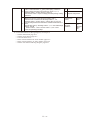
5. Reference Document.................................................................................................Ⅴ -1
(1) Outdoor Main Board Replacement Sequence and
Remote Controller Service Function.................... Ⅴ -1
(2) Outdoor Main Boards Switch/LED Configuration Diagram........................... Ⅴ -3
(3) Switch and LED................................................................................................. Ⅴ -4
(4) Display Component Specifications................................................................. Ⅴ -6
(5) Operation Unit Specifications.......................................................................... Ⅴ -7
(6) Normal Display (Level 0)................................................................................... Ⅴ -8
(7) Menu Display .................................................................................................. Ⅴ -10
(8) Ignition Timing Check and Adjustment......................................................... Ⅴ -47
(9) Thermistor characteristic graph.................................................................... Ⅴ -55
(10) Checks Prior to Automatic Addressing......................................................... Ⅴ -57
(11) Indoor/outdoor control wire connection confirmation................................. Ⅴ -58
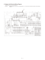
6. Outdoor Unit Electrical Wiring Diagram...................................................................Ⅵ -1
(1) Outdoor main board.......................................................................................... Ⅵ -2
(2) Outdoor power board........................................................................................ Ⅵ -3
(3) Converter board................................................................................................ Ⅵ -4
(4) Indoor control board for DC motor models..................................................... Ⅵ -5
(5) Indoor control board for AC motor models..................................................... Ⅵ -6
(6) Outdoor Unit Electrical Wiring Diagram.......................................................... Ⅵ -7
1.Symptoms that are not malfunctions
The following symptoms are characteristic operating conditions of this system and do not indicate malfunctions:
The fan flaps on the indoor unit operate when the unit is stopped
If the compressor outlet pressure exceeds 3.5 MPa during heating operation, the flaps on the stopped unit move to
horizontal and the fan rotates in the breeze.
When this happens, it may indicate a clogged air filter.
Inspect and clean if necessary.
Refrigerant noise is occasionally heard from the stopped indoor unit
During cooling operation of the outdoor unit, if the indoor unit is stopped for a period of time that equals the total
oil recovery time period while cooling (four hours), refrigerant will circulate in the stopped unit for four minutes, so
that refrigerant and oil can be recovered.
During heating operation of the outdoor unit, refrigerant will also flow in the stopped indoor unit, allowing recovery
of refrigerant and oil.
The fan in the outdoor unit rotates slowly
The outdoor unit fan can be completely stopped or rotated at various speeds by the control system, and will be fast
or slow as required. The fan is especially likely to stop or run slowly during cooling or heating operation when
outside temperatures are low.
During winter, the outdoor unit fan may rotate even when the engine is stopped.
The unit will not switch from cooling (dry) to heating, or from heating to cooling (dry)
• If “Being controlled by operation mode” is displayed
(When already being operated by another remote controller, the selectable operation modes are limited.)
When the following are displayed on the remote controller:
• If “Being controlled by operation mode” is displayed
(When already being operated by another remote controller, the selectable operation modes are limited.)
• If “Operation standby” is displayed
(In priority operation standby)
• If “Central control in progress” is displayed
(Operation is limited by the central control unit.)
• A display appears but then vanishes
(“Valve open” or “water circulation” has been set with the outdoor main board menu item No. 4, test operation
forced setting.)"
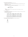
When the engine is started, an alarm displays on the 7 segment LED display.
Engine start standby is displayed during menu item No. 0, normal display.
If the unit is in start standby and each start condition is not accomplished when the engine is started, the
uncompleted start condition is displayed on the 7 segment LED. There are 5 types of start conditions, some that
start automatically after a set time, and some that become abnormal."
* See Ⅳ -1 4.-(3) for a list of startup conditions.
The outdoor unit does not operate at all
• The temperature controller is operating (thermo-off)."
Cooling is poor/heating is poor
• Is the temperature controller (remote controller temperature) properly set?
Is there too much load on the air conditioner?
• During demand control, because the unit operates at below the set fuel gas flow control value, cooling may be
slightly bad (heating may be slightly bad).
“Inspect oil” flashes on the remote controller.
When the operating hours for the gas engine reach a designated time, “Inspect oil” flashes.
Change the engine oil.
If the engine oil is not changed within 200 operating hours after flashing, warning A02 will be displayed and
operation will stop.
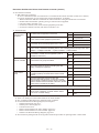
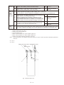
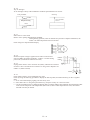
Ⅰ- 2.Before troubleshooting (W MULTI series)
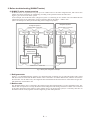
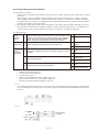
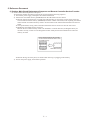
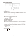
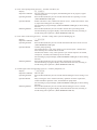
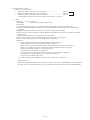
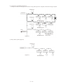
(1)W MULTI series system overview
W MULTI series is a system that can join up to two outdoor units to the same refrigerant tube, and control each
outdoor unit while performing air conditioning according to the operation load of the indoor unit.
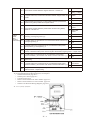
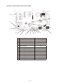
Figure 1 gives an overview of the system.
In the example, the W MULTI series (refrigerant system 1) connecting to two outdoor units and 3WAY MULTI
(refrigerant system 2) are linkwired by using an operation cable for the indoor - outdoor units.
(This is an example of a dual system consisting of two refrigerant systems.)
Refrigerant System 1
Refrigerant System 2
Indoor/outdoor control wire
Indoor/outdoor control wire
Refrigerant tubing (Outdoor branch tubing)*1
Balance tube*2
W MULTI
outdoor unit
1
W MULTI
outdoor unit
2
Indoor unit
2-2
Remote controller
(Indoor branch
tubing)
Indoor unit
2-1
Remote controller
Refrigerant
tubing
Remote controller
Indoor unit
1-48
Refrigerant tubing (main tubing)
Indoor unit
1-2
Remote controller
Remote controller
Refrigerant tubing (main tubing)
Indoor unit
1-1
Refrigerant tubing
(Indoor branch tubing)
3WAY MULTI
outdoor unit
1
Indoor/outdoor control wire
Fig. 1 GHP System Configuration Example
*1Refrigerant tube
Figure 1 is a simplified diagram. Actually, two refrigerant tubes consisting of a gas tube (thick tube) and a liquid
tube (thin tube) are used. Each W Multi outdoor unit is connected to an outdoor branch tube, and then connected to
the main tube. For the indoor unit, the refrigerant tubes branched from the main tube are connected to the gas tube
and liquid tube of each indoor unit.
*2Balance tube
The W Multi outdoor unit is connected to the refrigerant gas tube and liquid tube, as well as the balance tube. The
balance tube is required so as to keep the balance of the refrigerant and cooling oil between outdoor units connected
to the same refrigerant system. When a certain outdoor unit is cut off from the system, it is necessary that valve of
the balance tube is closed, together with the refrigerant gas tube and liquid tube.
Ⅱ- (2)About backup operation during maintenance work
● What is backup operation?
In the W MULTI series, multiple outdoor units are connected to the same refrigerant tube as shown in Figure 1.
Therefore, even during maintenance work of an outdoor unit, the other outdoor unit not required in maintenance
work can be used to keep the indoor operating conditions. This is called a backup operation.
● Backup operation procedure
To perform backup operation, the outdoor unit for maintenance work (hereafter referred to as "target outdoor
unit") must be cut off from the system using the following procedure. Review content of the maintenance work
and then select the most suitable method.
Also, after the maintenance work is finished, always refer to [System recovery procedure] and then return the
system to its normal state.
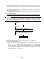
[Backup operation procedure]
To turn off power of target outdoor unit and then perform maintenance work (basic operation during inspection
of outdoor unit)
<<Important>>
This is the basic operation performed during inspection work. If this operation is not performed and the power
of the outdoor unit is turned off, this will cause system fault and prevent backup operation to be carried out, and
serious malfunction will occur. If this happens, see [System recovery procedure] to recover the system, and then
once again use the following procedure to perform setup. Automatic backup operation will kick in.
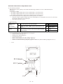
<<Step 1>>
On the outdoor main board of the target outdoor unit,
set the STOP switch (S001) to "STOP". *1
<<Step 2>>
(After confirming that the engine of the target outdoor
unit is stopped) close the valves of refrigerant gas tube,
refrigerant gas liquid tube, and balance tube.
<<Step 3>>
On the outdoor main board of the target outdoor unit,
set the STOP switch (S001) to "STOP". Wait for three
minutes or more and then turn off the circuit breaker of
the target outdoor unit. *2
Start maintenance work.
*1)Sometimes all outdoor units may stop. If there is operation input, outdoor units other than the target one will start
operation again after approximately five minutes. (For details on the settings, see the next item.)
*2)Always carry out the following three tasks.
Check to make sure <<Step 2>> is finished. If the shutoff valve is opened, refrigerant will flow from the
other outdoor unit to the target outdoor unit, causing serious malfunction.
After three minutes has elapsed from completion of <<Step 1>>, check to make sure the outdoor main board
displays " " and then perform this operation. If you turn off the power immediately after
performing "STOP" setting, the entire system will stop. (Backup operation cannot be performed.) If this
happens, see [System recovery procedure], recover the system, and then start over again starting from <<Step
1>>.
There will not be any problem whether the circuit breaker of the outdoor unit in <<Step 3>> is ON or OFF.
Select one of them according to the work required.
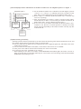
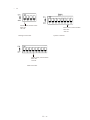
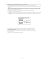
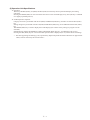
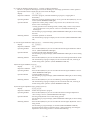
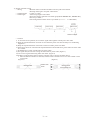
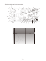
Ⅱ- [Work example] Perform maintenance on W MULTI outdoor unit 2 in refrigerant system 1 in Figure 1.
Refrigerant tubing
(main tubing)
Indoor/outdoor operation wiring
Refrigerant System 1
Refrigerant tubing(Outdoor
branch tubing)
Balance tube*2
W MULTI
outdoor unit
1
W MULTI
outdoor unit
2
a) For the W MULTI outdoor unit 2 indicated in the left diagram, perform
<<Step 1>> to <<Step 3>> in [Backup operation procedure] in that
order. Then, perform maintenance work on W MULTI outdoor unit 2.
b) When <<Step 3>> is finished, W MULTI outdoor unit 1 is reset.It'll stop
even if it is operating.)
c) After approximately five minutes, if there is operation input (indoor
remote controller is "Run" or test run setting on outdoor main board), W
Multi outdoor unit 1 starts up. (Backup operation starts.)
d) If test run is set from outdoor main board, W MULTI outdoor unit 1
continues to run. However, if normal operation is started by the indoor
remote controller, depending on the load, all outdoor units may stop due
to thermostat off.
<Procedure 1>
<Procedure 2>
<Procedure 3>
[System recovery procedure]
If backup operation has been performed, by all means check the following items after the maintenance work, and
then perform settings again to return the system to its normal state.
Check to make sure all shutoff valves of refrigerant gas tube, refrigerant liquid tube, and balance tube of the
outdoor unit are opened.
Check to make sure the STOP switch (S001) on the outdoor main board is set to "NORM".
If the power of the outdoor unit has been turned off, turn on the circuit breaker.
If "Test run" (No.4 Test- Cool/Heat) is set, cancel it.
* When adjusting to No.4 Test-Cool or Heat, if TEST/WARNING LED (D052) lights, this means "Test run" is
being set. In this state, press the SET (S007) key for one second or more. The setting will be canceled (TEST/
WARNING LED (D052) goes off.)
Ⅱ- 3.Malfunctions and Displays
(1)Malfunctions without any display
The circuit breaker trips when power is turned on
● Short circuit or ground fault of the crankcase heater, current leakage in electrical parts
Circuit breaker trips when operated
● Current leakage or short circuit in fan or coolant pump, current leakage or short circuit in electrical parts
Poor cooling
1)Problem in refrigeration circuit
● Clog in refrigeration circuit, faulty 4-way valve, faulty electric valve in indoor/outdoor unit, compression
failure, or shortage of refrigerant.
● Shutoff valve not completely open
2)Small fan capacity
● Clogged air filter, foreign matter in air inlet, outlet
3)Other
● Insufficient refrigerant tubing insulation
Poor heating
1)Problem in refrigeration circuit
● Clog in refrigeration circuit, faulty 4-way valve, faulty electric valve in indoor/outdoor unit, compression
failure, or shortage of refrigerant.
● Shutoff valve not completely open
2)Other
● Insufficient refrigerant tubing insulation
Heating on standby does not clear
● Warm air is striking the room temperature sensor, temperature around room temperature sensor is high, faulty
indoor control board
Auto-flap does not move well
1)The flaps swing, but wind direction cannot be set
● Auto-flap limit switch is faulty or has a bad connection
2)Does not move (swing, air direction setting)
● Auto-flap is faulty, indoor control board is failed, remote controller is faulty
Loud operation noise or vibration noise
1)Noise or vibration when fan operates
● Fan is unbalanced, worn motor axis bearing, loose fan securing screw
2)Loud operation noise or vibration noise when compressor operates
● Something is coming into contact with the refrigerant tubing or compressor
Water leakage
1)Drain water leakage
● Clogged drain tube, mistake in draintube construction, insufficient draintube insulation
2)Condensation on refrigerant tubing
● Insufficient tubing insulation
3)Condensation at duct outlet
● Insufficient wind capacity, gap between duct connections
Does not stop
● Fused magnetic contactors, faulty indoor/outdoor control board, faulty remote controller
No display on the remote controller
● Remote controller wiring disconnected
● Remote controller wiring shorted
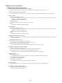
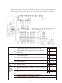
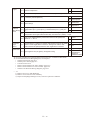
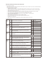
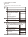
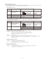
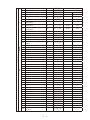
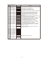
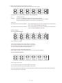
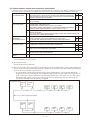
Ⅲ- (2) Remote Controller alarm display
: Flashing
Detection Item
Engine system error
Engine protective device operation
Starter system error
Engine oil pressure error
Engine oil error
Engine high-revolution error
Engine low-revolution error
Ignition power source error
Engine start failure
Fuel gas valve error
Engine stall
High exhaust gas temperature
Engine oil level error
Throttle error
Engine oil presure switch error
Crankshaft angle sensor error
Camshaft angle sensor error
Flameout error
Starter power source output short circuit
Starter lock
CT error (starter current detection failure)
Low coolant temperature
High coolant temperature
Coolant system error
Coolant level error
Coolant pump error
Clutch error
Catalyst temperature error (for only models with catalyst option)
Generator error (for only G POWER W MULTI)
Converter error (for only G POWER W MULTI)
Low fuel gas pressure error
Remote controller
Remote controller receive failure
detected an abnormal
signal from an indoor Remote controller transmission failure
unit
Indoor unit receive failure from remote controller (central)
Duplicate indoor unit address setting
Invalid setting
Multiple main remote controller units set
Communication errors, mis-setting
Indoor unit receive failure from signal output board
Automatic address setting is in progress, automatic address
setting start is prohibited
Indoor unit transmission failure to remote controller
Group control wiring communication failure
Indoor unit receive failure from outdoor unit
Indoor unit transmission failure to outdoor unit
Outdoor unit receive failure from indoor unit
Outdoor unit transmission failure to indoor unit
Too few units
Automatic address
alarm
Too many units
No indoor unit in automatic address setting
Outdoor main board error
Outdoor main board sensor error
Warning
Display
A01
A02
A03
A04
A05
A06
A07
A08
A10
A11
A12
A14
A23
A24
A26
A15
A16
A17
A19
A20
A21
A22
A25
A27
A28
A29
A30
E01
: Lit
Wireless Remote Control
Lamp Display
Operating
Timer
E09
E11
Outdoor unit
Simult. flashing
Remote
controller
Operating
Timer
Wait...
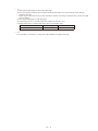
Communication failure between outdoor units (for only W MULTI)
E24
Inconsistencies in number of outdoor units (for only W MULTI)
Incorrect outdoor unit tube connection (for only W MULTI)
Communication failure between units
E26
E28
E31
Indoor unit
Remote
controller
Indoor unit
Flashing
E12
E13
E18
E04
E05
E06
E07
E15
E16
E20
E21
E22
Device
Checked
Wait...
E02
E03
E08
: Off
Outdoor unit
Indoor unit
Indoor unit
Operating
Timer
Wait...
Flashing
Outdoor unit
When the water heat exchanger unit is connected in the table above, please replace indoor unit with water
heat exchanger unit for the alarm.
Note: Some items are not indicated, depending model.
1
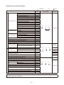
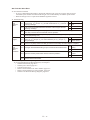
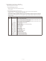
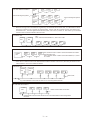
Ⅲ- : Lit
: Flashing
Warning
Display
Detection Item
Indoor unit sensor
errors
Sensor errors
Indoor heat exchanger inlet temperature
sensor error (E1)
F01
Water heat exchanger unit anti-icing
sensor error
F02
Indoor heat exchanger outlet temperature
sensor error (E3)
F03
Indoor unit intake temperature sensor error
F10
Indoor unit discharge temperature sensor
error
F11
Compressor outlet temperature sensor error
F04
Outdoor heat exchanger inlet temperature
sensor error
Outdoor heat exchanger outlet temperature
sensor error
Outside air temperature sensor error
Outdoor unit sensor
Compressor inlet temperature sensor error
errors
Coolant temperature sensor error
Compressor inlet/outlet pressure sensor
error
Hot water outlet temperature sensor error
(for only models that discharge hot water)
Exhaust gas temperature sensor error
Clutch coil temperature sensor error
Clutch 2 coil temperature sensor error
Temperature sensor error for oil level
measurement (for only W MULTI)
Compressor oil depletion error (for only W MULTI)
Wireless Remote Control
Lamp Display
Operating
Device
Checked
Wait...
Indoor unit
Alternate flashing
F06
F07
F08
F12
F13
Operating
Timer
Wait...
Lit
Alternate flashing
Outdoor unit
F16
F17
F18
F20
F21
Operating
H08
Timer
Wait...
Flashing
H07
Operating
Indoor nonvolatile memory (EEPROM) error (*1)
Timer
: Off
Timer
Wait...
F29
Indoor unit
Simult. flashing
Operating
Real time clock (RTC) function
F30
Outdoor nonvolatile memory (EEPROM) error
F31
Invalid or missing setting
Inconsistencies in indoor/outdoor unit models (non-GHP
equipment connected)
Multiple main units set for group control
Duplicate indoor unit (priority indoor unit)
priority setting
(excluding priority indoor unit)
Group control wire present for individual-control indoor unit
Indoor unit address not set
Indoor unit capacity not set
Duplicate system (outdoor unit) address setting
Outdoor unit capacity not set
Indoor unit model setting failure
Indoor unit pairing failure
Gas type setting failure
Timer
Simult. flashing
Wait...
Lit
L02
L03
L05
L06
L07
L08
L09
L04
L10
L13
L15
L21
Operating
Timer
Wait...
Outdoor unit
Indoor unit
Outdoor unit
Simult. flashing
Operating
Timer
Lit
Indoor unit
Wait...
Outdoor unit
Simult. flashing
When the water heat exchanger unit is connected in the table above, please replace indoor unit with water
heat exchanger unit for the alarm.
Note: Some items are not indicated, depending in model.
Ⅲ- 2
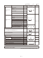
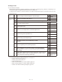
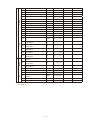
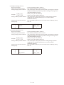
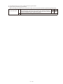
: Flashing
Warning
Display
P09
Detection Item
Indoor unit ceiling panel connector connection failure
Protective device operation
Indoor protection
devices
Outdoor protection
devices
Indoor fan error / indoor fan rpm error
P01
Indoor unit float switch operation
P10
Indoor DC fan error
P12
High compressor discharge temperature
Refrigerant high-pressure switch operation
Power source error
P03
P04
P05
Water heat exchanger unit anti-icing sensor
error (for only water heat exchanger unit)
P11
Refrigerant circuit error
(for only W MULTI and 3WAY MULTI)
O2 sensor operation
Complete refrigerant gas depletion
Bypass valve error
4-way valve lock error
(not detected 3WAY MULTI)
Refrigerant high-pressure error
Outdoor fan error
P13
P14
P15
P18
P19
P23
Clutch connection error
P26
Group control's sub unit error (system controller)
P30
Group control error (alarm)
Oil change time (level) alarm
P31
Automatic backup operation (*2)
Backup operating display without power generation when the
converter is abnomal
Wireless Remote Control
Lamp Display
Timer
Operating
: Off
Device
Checked
Wait...
Indoor unit
Alternate flashing
Outdoor unit
Operating
Timer
Wait...
Alternate flashing
P20
P22
Water heat exchanger unit interlock error
(for only water heat exchanger unit)
Outdoor display: oiL
: Lit
System
controller
Indoor unit
Oil check
check
Outdoor unit
GE
When the water heat exchanger unit is connected in the table above, please replace indoor unit with water
heat exchanger unit for the alarm.
Note: Some items are not indicated, depending in model.
*1: If the indoor nonvolatile memory (EEPROM) is faulty when the power supply is turned on, Alarm code F29 is not
indicated, but the power source LED on the indoor board starts to flicker.
*2: In this case, operation of the system is possible, but one of the outdoor units is detected to have stopped
abnormally.
● Alarm P30 (group controlled device fault) is sometimes displayed at the system controller.
Ⅲ-
3
4.Error Display and Troubleshooting
The description of each error display begins on a new page. Descriptions of some troubleshooting procedures span
several pages. When you refer to an error display, be sure to first check whether the description of the troubleshooting
procedure spans several pages.
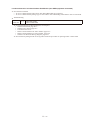
(1)Precautions before Troubleshooting
In order to ensure correct diagnosis and prevent accidents (electric shock, equipment malfunction, measuring
instrument damage, etc.), be sure to observe the following precautions.
Be sure to use a digital tester for voltage measurement
Avoid using a tester with an indicator needle to prevent large measurement errors or operation failure.
Unless otherwise specified, perform voltage measurement with the terminal (terminal plate and connector)
connected
In some cases, measurement is also performed with the terminal disconnected.
Perform continuity measurement (resistance measurement) after disconnecting the terminals on both ends
Performing continuity measurement while the terminals are connected will cause a short circuit or damage to the
tester.
If instructed to disconnect wires before performing continuity or voltage measurement, be sure to do so, then
reconnect the wires before proceeding to the next step (item)
Be sure to turn off the power before connecting or disconnecting wires
Be careful not to touch any live parts (energized components) with a hand or tool while performing voltage
measurement
For DC voltage measurement, the polarity is indicated by + or - after the terminal name (symbol) to prevent
confusion
Connect the red lead of the tester to the + side and the black lead to - side.
(2)About the Error Detection Procedure
Some abnormal occurrences are determined as abnormalities the first time they are detected and some are not
determined to be abnormalities until they are detected multiple times.
In the latter case, the engine is not forced to shut down the first time an abnormal occurrence happens. Instead, data
on the abnormal occurrence is stored in nonvolatile memory, the engine is force stopped for a period of 3 minutes,
and then the engine enters the restart sequence.
In the error detection procedures described on the subsequent pages, abnormal occurrences that are determined
as abnormalities after being detected multiple times (e.g. 5 times) are taken to mean abnormal occurrences that
are continually detected multiple times (e.g. 5 times) within 1 hour of engine operation. Regardless of continual
occurrence and engine operation time, the cumulative number of occurrences (e.g. 5 times) may force the engine to
shut down.
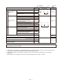
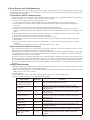
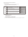
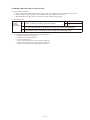
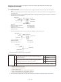
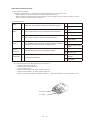
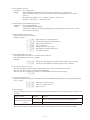
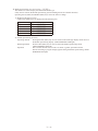
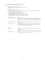
(3)Engine Start Standby
●When the engine is in standby mode waiting for the startup conditions to be met, the conditions that have not yet
been met are displayed on the 7-segment LED display.
●There are 6 startup conditions. Some conditions start the engine automatically after a specified time period, while
others cause it to stop with a warning.
●Display Method
The startup conditions (see table below) light at engine start up (No. 0 normal display only)
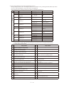
●Startup Conditions Displayed in Engine Start Standby Mode
Start condition
Start Standby
Display Code
Refrigerant pressure
equalization (between high
and low pressure areas)
Compressor outlet
temperature
Completely run out of gas
Coolant temperature
Coolant level
Coolant circuit
Engine oil level
No condenser (3WAY
model only)
No evaporator (3WAY
model only)
Condition
Pressure equalizing display (max. 2 min.)
Waiting for the temperature to drop to below 115°C (If the
temperature does not go down within 10 minutes, the engine is
malfunction error.)
Waiting for the compressor inlet pressure to exceed 0.1 MPa.
(If the pressure is not restored within 10 minutes, the engine is
malfunction error.)
Waiting for the temperature to drop to below 80°C (If the
temperature does not go down within 10 minutes, the engine is
malfunction error.)
If the coolant level is not restored within 3 minutes, the engine is
malfunction error.
Waiting for the coolant pump to exceed a minimum -1 of 2500 rpm (If
not restored within 3 minutes, the engine is malfunction error.)
If the engine oil level is not restored within 60 minutes, the engine
is forced to shut down.
Waiting for 3WAY solenoid valve in indoor or outdoor unit to
complete switching and system is able to capture the condenser
Waiting for the 3WAY solenoid valve in indoor or outdoor unit
to complete switching and the system is able to capture the
evaporator
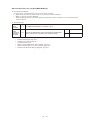
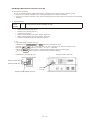
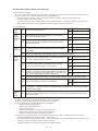
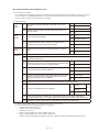
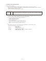
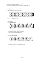
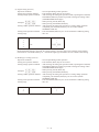
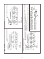
Ⅳ- (4)Troubleshooting
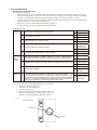
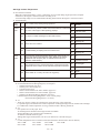
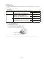
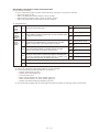
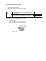
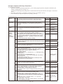
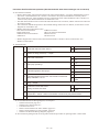
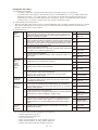
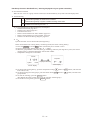
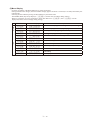
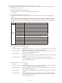
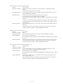
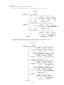
A01 Engine Oil Pressure Error
Error detection method
• When the engine oil pressure switch is OFF continuously for 3 second during engine operation (complete
combustion), the engine is shut down momentarily and an error flag is set. An Engine Oil Pressure Trouble
condition is assumed when the error flag has stopped the engine 5 consecutive times in 1 hour.
* At engine startup, code A06 reports an engine pressure trouble occurring within 15 seconds of detecting the
opening of gas valve 1. (It is not reported by A01.)
• Engine oil pressure switch: Setting value 49kPa (0.5kg/cm2)
Contact ON with oil pressure (common ground with engine)
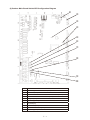
Troubleshooting
1
Oil level
Yes 2-1
1-1 Is there oil in the storage side of the oil tank?
No
1-2 Any oil leaks or dirty oil?
No
No
No
1-5
Yes Repair wiring
1-5 Any oil fill pump wiring broken or disconnected?
No
After engine operation (complete combustion), does the voltage between
the oil pressure switch terminal (+) and body ground (–) measure DC 0V?
2-2 At engine start, does the oil pressure measure 49kPa (0.5kg/cm2) or more?
Replace pump
Yes 3-1
No
2-2
Yes
Oil pressure
switch defective
No
2-3
Yes Replace oil filter
2-3 Is the oil filter clogged?
3
Wiring
1-4
Check for
Yes pinched or
clogged hose
1-4 Does the oil fill pump operate properly?
2-1
1-3
Yes Add oil
1-3 Is the tank side of the oil tank empty?
2
Oil
pressure
switch
1-2
Yes Repair
No
Does any of the wiring below contain broken wires or suffer from poor
connection, contact or crimping? • Wiring from outdoor main board
connector 2P(red) CN012 No. 1 to oil pressure • Wiring from outdoor main
3-1
board connector 2P (red) CN021 No. 1 to power board connector 2P (red)
CN038 No. 1 Wiring between switches • Wiring from outdoor main board
connector FG CN075 to (-) terminal on starter power supply
● For work procedure for replacing outdoor main board, see “5. Reference Document”.
● For board and Electrical Wiring Diagram, see Chapter 6.
• Outdoor main board: page VI-2
• Outdoor power board: page VI-3
• Converter board: VI-4
• Indoor control board for DC motor models: page VI-5
• Indoor control board for AC motor models: page VI-6
• Outdoor Unit Electrical Wiring Diagram: page VI-7
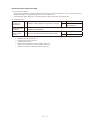
•1-1
Oil tank, top view
Storage side
Tank side
Ⅳ- Engine is
defective
Yes Repair wiring
No
Replace outdoor
main board
•2-1
Engine oil pressure switch
120/150/190/240 models
• 3-1
With oil pressure: DC0V
No oil pressure: DC12V
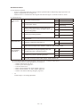
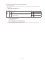
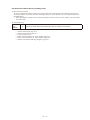
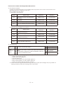
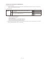
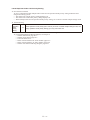
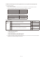
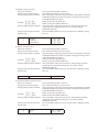
Ⅳ- A02 Engine Oil Error
Error detection method
When the oil change hours exceed the oil change hours (EEPROM setting), or, after error is reset for said status,
when the oil change error hours (EEPROM setting: However, after 6th reset this is 4 hours) have passed. Engine
is stopped when error occurs.
Note : • When the gas type setting is “1”, no engine oil error is detected.
• After changing engine oil, use the procedure describe in (2) below to reset the oil change hours timer.
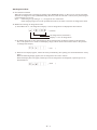
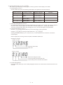
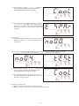
Method for resetting oil change hours timer
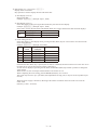
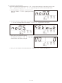
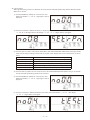
1) Select Menu No. 2 “Oil change hours display”. The oil change hours are displayed as shown below.
(o10100)
Oil change hours (10100 hours)
Displays “o” for oil change hours
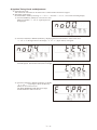
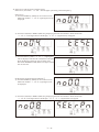
2) By holding down the set key while displaying the oil change hours, the display changes to the following.
Also, if an operation error results in this display, simply wait for about one second to return to the previous
oil change hours display.
(CLr
)
3) When the CLr display appears, release the set key momentarily, then quickly press and hold down the set key
again.
When the following display appears, the oil change hours are reset to 0 hours.
When this display does not appear, and the previous oil change hours are displayed, repeat the process as
described above.
(End
Ⅳ- )
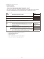
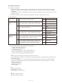
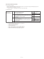
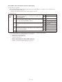
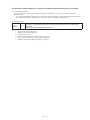
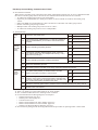
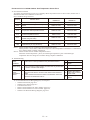
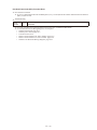
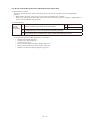
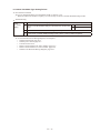
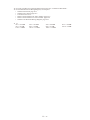
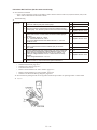
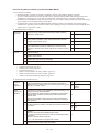
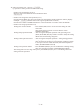
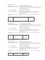
A03 Engine High-Revolution Error
Error detection method
Engine revolution speed is,
• Engine revolution speed is more than 2,300min-1 continuously for 30 seconds
• Engine revolution speed is more than 2,400min-1 continuously for 10 seconds
• Engine revolution speed is more than 2,500min-1 continuously for 1 second
If any of above conditions occur, the engine stops momentarily and an error flag is set. An Engine Speed Too
High trouble is assumed when the error flag has stopped the engine 5 consecutive times in 1 hour. "
Troubleshooting
1
Check
revolution
speed
1-1
2
Mixer
2-1 Is the throttle valve locked or sticking?
Measure actual revolution speed using a revolution meter. Was there
high revolution when the error occurred?
3
Compressor 3-1 Does the compressor have any reason for abnormally low load?
4
Ignition
pulse
5
Wiring
6
Mixer
Yes 2-1
No
4-1
Yes Repair
No
3-1
OK 5-1
NG Restore
4-1 Ignition coil, cam angle sensor, and crank angle sensor
• Any poor connections, poor contact or broken wires between throttle
(step motor) wiring and connector? (Wiring from outdoor main board
5-1 connector 6P (black) CN066 to throttle (step motor))
• In the relay part, is the wiring for the throttle (step motor) and fuel
regulating valve crossed?
Reset the power
Yes after repair
wiring
Does the throttle (step motor) coil resistance measure about 120Ω?
6-1 (Disconnect relay connector 6P-1, and measure between No. 1 (red)
and No. 2/No. 3, and between No. 4 (orange) and No. 5/No. 6.)
Yes 6-2
Is 4 V DC applied between control board connector 6P (black) CN066
6-2 No. 1 (+) and No. 2 (-)/No. 3 (-) as well as between No. 4 (+) and No. 5
(-)/No. 6 (-) when turning the power ON (during positioning)?
Yes Replace mixer
● For work procedure for replacing outdoor main board, see “5. Reference Document”.
● For board and Electrical Wiring Diagram, see Chapter 6.
• Outdoor main board: page VI-2
• Outdoor power board: page VI-3
• Converter board: VI-4
• Indoor control board for DC motor models: page VI-5
• Indoor control board for AC motor models: page VI-6
• Outdoor Unit Electrical Wiring Diagram: page VI-7
Ⅳ- No
No
No
6-1
Replace mixer
Replace outdoor
main board
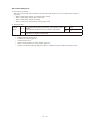
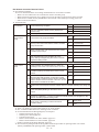
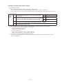
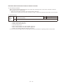
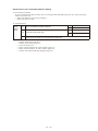
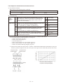
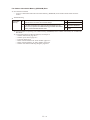
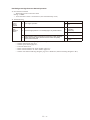
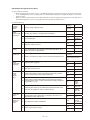
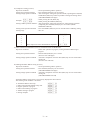
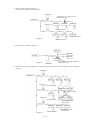
A04 Engine Low-Revolution Error
Error detection method
• When engine revolution speed drops to 700min-1 or less continuously for 3 seconds during engine operation
(complete combustion), an abnormal flag is set and the engine stops. An Engine Speed Too Low condition is
assumed when the error flag has stopped the engine 5 consecutive times in 1 hour.
Troubleshooting
1
Fuel
1-1 Has the fuel gas pressure dropped? Is the fuel empty?
2
Check
revolution
speed
2-1
3
Mixer
3-1 Is the throttle valve operating?
4
Ignition
pulse
4-1 Check ignition coil, cam angle sensor, and crank angle sensor.
5
Wiring
6
Engine
Measure actual revolution speed using a revolution meter. Is the
revolution actually low?
OK 2-1
NG Restore
Yes 3-1
No
4-1
Yes 6-1
No
5-1
Any poor connections, poor contact or broken wires between throttle (step Yes Repair wiring
5-1 motor) wiring and connector?(Wiring from outdoor main board connector
No 8-1
6P (black) CN066 to throttle (step motor))
6-1 Measure compression (See A06 5-1).
OK 6-3
NG 6-2
6-2 Wash valve and adjust valve clearance. If still NG, replace engine head.
Yes 6-6
6-3 Are sparks emitted properly?
No
OK 6-5
6-4 Inspect ignition plug.
NG Replace
6-5 Ignition coil, cam angle sensor, and crank angle sensor
6-6 Inspect zero governor (see A06 3-1).
8
Mixer
7-1
OK
Replace high
tension cord
NG Repair
OK 6-7
NG Restore
OK 7-1
6-7 Ignition timing? (see A06 5-4)
7
Fuel gas
regulating
valve
6-4
NG Adjustment
Does the fuel regulating valve (step motor) coil resistance measure
about 120Ω? (Disconnect relay connector 6P-6 and measure between
No. 1 (red) and No. 2/No. 3, and between No. 4 (orange) and No. 5/No.
6.)
OK 7-2
NG Replace mixer
Is 4 V DC applied between outdoor main board connector 6P (red)
7-2 CN065 No. 5 and No. 1/No. 2 as well as between No. 3/No. 4 when
turning the power ON (during positioning)?
Yes Replace mixer
Does the throttle (step motor) coil resistance measure about 120Ω?
8-1 (Disconnect relay connector 6P-2, and measure between No. 1 (red)
and No. 2/No. 3, and between No. 4 (orange) and No. 5/No. 6.)
Yes 8-2
No
No
8-1
Replace mixer
Yes Replace mixer
Is 4 V DC applied between outdoor main board connector 6P (black)
8-2 CN066 No. 1 (+) and No. 2 (-)/No. 3 (-) as well as between No. 4 (+) and
Replace outdoor
No. 5 (-)/No. 6 (-) when turning the power ON (during positioning)?
No
main board
● For work procedure for replacing outdoor main board, see “5. Reference Document”.
● For board and Electrical Wiring Diagram, see Chapter 6.
• Outdoor main board: page VI-2
• Outdoor power board: page VI-3
• Converter board: VI-4
• Indoor control board for DC motor models: page VI-5
• Indoor control board for AC motor models: page VI-6
• Outdoor Unit Electrical Wiring Diagram: page VI-7
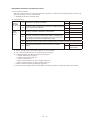
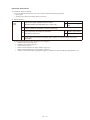
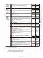
Ⅳ- A05 Ignition Source Error
Error detection method
When the starter power output meets the following conditions, an error is detected upon 5 consecutive
occurrences in one hour.
• When an ignition voltage decrease is detected for 2.5 seconds or more.
• During cranking, when I<3.8A is detected for 4 seconds, with no revolution pulse.
Note) The starter power source magnet switch (52S) operation is as follows.
• When power is turned on, 52S turns ON upon operation signal input. If no abnormalities occur thereafter
(A15,A16, A17), this stays ON, and turns OFF upon stop signal input.
• Turns OFF when error occurs.
Troubleshooting
Try operating the outdoor unit.
• When the starter power source magnet switch (52S) does not turn ON: Go to 1-1
• When the starter power source magnet switch (52S) turns ON, and then turns OFF after 3 seconds: Go to 2-1
• When the starter power source magnet switch (52S) turns ON but the starter does not turn ON: Go to 4-1
1
Starter
power
source
magnet
switch
(52S)
Replace magnet
switch
No
1-2
At magnet switch ON timing, is there AC200V between magnet switch
A1 and A2?
1-2
At magnet switch ON timing, is there AC200V between power board
connector 3P (yellow)/CN028 No. 1 and No.3?
1-3
Wiring connection/contact poor between power board connector 3P (red)/CN028 and magnet
switch A1-A2 → Repair wiring
1-4
Is there AC200V between power board connector 5P (yellow)/CN002
No. 1 and No. 2 ?
2
Ignition coils 2-1 At magnet switch ON, is there DC11V or more between outdoor main
board connector 2P (black) CN006 No. 1 (+) and No. 2 (–)?
Yes 1-3
No
1-4
Yes
Replace Power
board
No
2-1
Yes
Replace control
board
No
2-2
With outdoor main board connectors 6P (white) CN010 and 6P (black)
CN011 disconnected, at magnet switch ON, is there DC11V or more
between outdoor main board connector 2P (black) CN006 No. 1 (+) and
No. 2 (–)?
Yes 2-3
2-2
No
2-4
2-3
Check for wiring ground fault or short-circuit from outdoor main board
connector 6P (white) CN010 and 6P (black) CN011 to each ignition coil.
OK
Replace ignition
coil
2-4
At magnet switch ON, is there AC11V or more between power board
connector 2P (white) CN022 No. 1 and No. 2?
Wiring connection/contact poor, or wire broken, between power board
2-5 connector 2P (black) CN025 and outdoor main board connector 2P
(black) CN006?
3
Ignition
(starter)
power
source
Yes
1-1
NG Repair wiring
Yes 2-5
No
3-1
Yes Repair wiring
No
Replace power
board
Yes
3-1
At magnet switch ON, is there about AC11V between starter power
source relay connector 2P-18 (black) No. 1 and No. 2?
3-2
Wiring connection/contact poor, or broken wire, between power board connector 2P (white)/
CN022 and starter power source relay connector 2P-7 (black) → Repair wiring
3-3
At magnet switch ON, is there AC200V between starter power source
relay connector 2P-4 (white) No. 1 and No. 2 ?
3-4
At magnet switch ON, is there about AC200V between magnet switch
No. 2 and No. 6?
3-5
Wiring connection/contact poor, or broken wire with wiring between magnet switch and starter
power source relay connector 2P-4 (white) → Repair wiring
Ⅳ- No
Yes
Replace starter
power source
No
Yes
No
3-6 Is there about AC200V between magnet switch No. 1 and No. 5?
3-7
At magnet switch ON, is there about AC200V between magnet switch A1
and A2?
3-8
Wiring connection/contact poor, or wire broken, between power board
connector 3P (yellow) CN028 and magnet switch?
3-9
Is there about AC200V between power board connector 5P (yellow)/
CN002 No. 1 and No. 3?
4
At magnet switch ON, is there DC10V or more between starter B
Starter/
4-1
terminal (+) and engine ground (–)?
starter
relay
(Outdoor
there about
AC230V
between ray
boardSconnector
thereIsDC10V
or more
between
starter
terminal (+)
main board) 4-2 At cranking timing, is 3-9
and engine ground (–)? 3P (green)/CN005 No. 1 and No. 3?
4-3
4-4
4-5
4-6
4-7
Yes 3-7
No
Check primary
wiring → Repair
Yes
Replace magnet
switch
No
3-8
Yes Repair wiring
No
3-9
Yes
Replace power
board
No
Check relevant
wiring filter
board
Yes 4-2
No
Yes
Yes
No
No
4-3
Replace power
Replace starter
board
Check relevant
wiring
4-5
Yes
Yes 4-2
4-4
No
4-3
Yes
No Replace
3-3 starter
relay (control
4-2
starter S terminal (+) and engine ground (–)?
board)
No
4-5
Wiring connection/contact At
poor
between starter power source positive terminal
and starter B
magnet switch ON, is there DC10V or more between
Yes 4-4
terminal, or between 4-3
starter
power
source
and(–)?
engine ground → Repair wiring
starter
power
sourcenegative
positive (+)terminal
and negative
No
3-3
positive
Wiring connection/contact poor between starter power source
Yes
4-6terminal and
At cranking timing, is 4-4
therestarter
DC10V
or more
between
power
board
B terminal,
or between
starter
power
source negative terminal and engine
connector CN084 (+) and outdoor
ground m main
Repairboard
wiring connector FG CN075 (–)? No 4-7
At cranking timing, is there DC10V or more between
Yes 4-6
4-5 ray
board
connector
and control CN084
board
Wiring connection/contact
poor
from
powerCN002
board(+)connector
(+) to starter S terminal →
No
4-7
connector FG CN075 (–)?
Repair wiring
Wiring connection/contact poor from power board connector CN084 (+) to starter S
4-6 terminal m Repair wiring
Replace outdoor
Yes
At magnet switch ON, is there DC10V or more between
4
At magnet
switch ON,4-1is there
DC10V
or (+)
more
between
starter
starter
B terminal
and engine
ground
(–)? power
Starter/starter
source
positive (+) and negative
(–)?
At cranking timing, is there DC10V or more between
At magnet switch ON, is there DC10V or more between power board
main board
At magnetmain
switchboard
ON, is there
DC10VFG
or more
between
connector CN084 (+) and outdoor
connector
CN075
(–)? Yes Replace control
4-7 ray board connector CN084 (+) and control board
No board
4-8
connector FG CN002 (–)?
No
4-8
Wiring connection/contact Wiring
poor from
power board connector CN085 (+) to starter power source
connection/contact poor from ray board connector CN002 (+) to starter
4-8
4-8
positive terminal → Repair
wiring
power source positive terminal m Repair wiring
『5.参考資料』の項を参照してください。
● For work procedure ●室外メイン基板交換時の作業手順については、
for replacing outdoor main board, see “5.
Reference Document”.
●基板および電気配線図は、6
● For board and Electrical
Wiring Diagram, see 章を参照してください。
Chapter 6.
・ 室外メイン基板:Ⅵ-2ページ
• Outdoor main board: ・
page
VI-2
室外パワー基板:Ⅵ-3ページ
• Outdoor power board:・page
VI-3
DC モーター機種用室内コントロール基板:Ⅵ-4ページ
• Converter board: VI-4・ AC モーター機種用室内コントロール基板:Ⅵ-5ページ
・ 室外ユニット電気配線図:Ⅵ-6ページ
*参照(電気配線図 B~F-1~3)
• Indoor control board for
DC motor models: page VI-5
• Indoor control board
for AC motor models: page VI-6
・3-1~3-5、4-3、4-4、4-6、4-8
• Outdoor Unit Electrical Wiring Diagram: page VI-7
● 3-1~3-5,4-3,4-4,4-6,4-8
III – 13
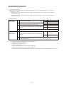
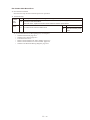
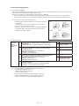
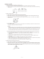
Ⅳ- A06 Engine Start Failure
Error detection method
1. When startup cannot be confirmed (but revolution speed is detected) 6 seconds after detecting the opening of
gas valve 1 at startup.
2. At engine startup when there is no oil pressure switch input 15 seconds after detecting the opening of gas
valve 1.
Error input is structured as shown below.
Troubleshooting
1
Engine
2
Plug
1-1
Has the fuel gas pressure dropped? Is the fuel empty? Measure the
pressure at the gas pressure measuring port during cranking.
1-2
Is the gas solenoid valve SW (S002 on outdoor main board) on the
NORMAL side?
2-1
Are sparks emitted properly? (Remove plug and check independently.
Or, check with timing light.)
Any poor connections, poor contact, poor crimping or broken wires
2-2 between ignition wiring and outdoor main board connector 6P (white)/
CN010 and 6P (black)/CN011?
4
Gas
solenoid
valve/Gas
adjustment
valve
NG 1-2
Yes 4-1
No
Switch to
NORMAL
Yes 3-1
No
2-2
Yes Repair wiring
No
2-3
OK 7-1
2-3 Inspect ignition plug.
3
Zero
governor
OK 2-1
NG Replace plug
OK 5-1
3-1 Inspect zero governor.
NG Restore
During cranking, is there DC180V between fuel gas solenoid valve relay Yes 4-2
4-1 connector 4P-1 (white) No. 1 (+) and No. 2 (–), and No. 3 (+) and No. 4
No 6-1
(–)?
During cranking, is a voltage of DC180V or more applied across
4-2 terminals of fuel gas solenoid valve coil? For gas-type C models, go to
4-4.
Yes 4-4
No
4-3
4-3
Poor wiring connection/crimping, or broken wire, between fuel gas solenoid valve relay
connector 4P-1 (white) and solenoid valve → Repair wiring
4-4
Poor fuel gas solenoid valve operation (Replace after checking for any foreign matter blocking
the fuel gas passage, etc. No abnormalities: go to 4-5)
4-5 Throttle (step motor) and fuel gas regulating valve operating properly?
Ⅳ- 5
Engine
OK 5-3
5-1 Measure compression.
NG 5-2
5-2 Wash valve and adjust valve clearance. If still NG, replace engine head.
OK 5-4
5-3 Air cleaner? (visual inspection)
NG Clean/replace
OK
5-4 Ignition timing?
Keep under
observation
NG Adjustment
6
During cranking, is there 180 V DC between power board connector 7P Yes 6-2
Solenoid
6-1 (white) CN041 pin 1 (+) and pin 3 (–)? And between pin 5 (+) and pin 7
valve wiring/
(–)?
No 6-3
board
Poor connection/contact/crimping or broken wire for wiring from power board connector 7P
6-2
(white)/CN041 to fuel gas solenoid valve relay connector 4P-1 (white) → repair
6-3
7
Crank/cam
angle
sensor
Is 200 V AC applied between power board connector 3P (white) and
CN002 No. 1 - No. 2?
Yes
Replace power
board
No
7-1
Any poor connections, poor contact, poor crimping or broken wires in
Yes Repair wiring
the wiring below? • Wiring from outdoor main board connector 3P (white)
7-1
CN015 to crank angle sensor connector • Wiring from outdoor main
No 8-1
board connector 3P (black) CN016 to cam angle sensor connector
8
Ignition Coil
Yes Repair wiring
8-1 Inspect ignition coil (coil, igniter), and ignition wiring.
● For work procedure for replacing outdoor main board, see “5. Reference Document”.
● For board and Electrical Wiring Diagram, see Chapter 6.
• Outdoor main board: page VI-2
• Outdoor power board: page VI-3
• Converter board: VI-4
• Indoor control board for DC motor models: page VI-5
• Indoor control board for AC motor models: page VI-6
• Outdoor Unit Electrical Wiring Diagram: page VI-7
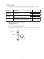
• 3-1
1) Remove front cover and diaphragm.
2) Remove valve and valve lever assembly.
3) Inspect for diaphragm damage or tears, and valve operation conditions.
Ⅳ- 10
No
A01
Troubleshoot
engine oil
pressure trouble
• 5-1
1) After warming the engine, remove all spark plugs.
2) Force the fuel gas solenoid valve off (trial operation and outdoor unit forced setting> force fuel gas
solenoid valve off)
* When the gas solenoid valve force switch (S002) is used to close the gas solenoid valve, an A07 is issued
before cranking.
3) Set compression gauge in spark plug hole.
4) Crank engine for 4 to 5 seconds (operation signal/trial operation, etc.).
5) Repeat three times to confirm that gauge value exceeds limit value.
For G POWER engine
Gas type
Limit value
G
1.62MPa
• 5-4
For procedures, see Chapter 5 “Inspection and Adjustment of Ignition Timing.”
Ⅳ- 11
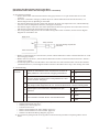
A07 Fuel Gas Valve Error
Error detection method
• An error is determined when either or both of the following gas valves do not open: fuel gas valve 1
controlled by the outdoor main board and fuel gas valve 2 controlled by the outdoor power board.
• When the fuel gas valve is open but the feedback signal has ceased.
Troubleshooting
1
Gas
solenoid
valve
Yes 1-2
Is 180 V DC being applied between the fuel gas solenoid valve relay
1-1 connector No. 1 (+) and No. 2 (-) as well as between No. 3 (+) and No. 4
No 1-3
(-) during cranking?
1-2
Is 180 V DC being applied between terminals of the fuel gas solenoid
coil during cranking?
Yes 1-4
No
1-3
Repair poor connection, poor crimping, broken wires in wiring between the fuel gas solenoid
1-3
valve relay connector and the solenoid valve or replace it.
1-4
2
Engine
Is 180 V DC applied between the power board connector 7P (white)
2-1 CN041 pin 1 (+) and pin 3 (-) as well as between pin 5 (+) and pin 7 (-)
during cranking?
2-2
3
Gas
solenoid
valve
Feedback
Poor fuel gas solenoid valve operation (Replace after checking for any foreign matter blocking
the fuel gas passage, etc.)
Yes 2-2
No
Power board
Poor connection, contact, crimping or broken wires in wiring between the power board
connector 7P (white) CN041 and fuel gas solenoid valve relay connector. Repair or replace.
3-1 Check gas valve feedback wiring for poor connection and broken wires.
3-2 Repair the outdoor power board. Did this solve the problem?
3-3 Replace outdoor main board.
● For work procedure for replacing outdoor main board, see “5. Reference Document”.
● For board and Electrical Wiring Diagram, see Chapter 6.
• Outdoor main board: page VI-2
• Outdoor power board: page VI-3
• Converter board: VI-4
• Indoor control board for DC motor models: page VI-5
• Indoor control board for AC motor models: page VI-6
• Outdoor Unit Electrical Wiring Diagram: page VI-7
Ⅳ- 12
Yes
Repair/replace
wiring
No
3-2
Yes
Defective power
board
No
3-3
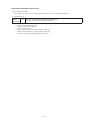
A08 Engine Stall
Error detection method
During engine operation (complete combustion), when engine revolution speed ≤ 100min-1 continuously for 3
seconds, the engine is stopped momentarily and an error flag is set.
An Engine Stall condition is assumed when the error flag has stopped the engine 5 consecutive times in 1 hour.
Troubleshooting
1
Fuel
1-1 Has the fuel gas pressure dropped? Is the fuel empty?
2
Engine
2-1 Measure compression (See A06 5-1).
OK 2-1
NG Restore
OK 2-3
NG 2-2
2-2 Wash valve and adjust valve clearance. If still NG, replace engine head.
Yes 2-6
2-3 Are sparks emitted properly?
No
2-4 Inspect ignition plug.
NG Replace
2-5 Ignition coil, cam angle sensor, and crank angle sensor
2-6 Inspect zero governor (see A06 3-1).
2-7 Ignition timing? (see Chapter 5 (9)).
2-8
"Air intake occurring? Check rubber plug on intake
manifold."
2-9 Fuel gas regulating valve operating properly?
2-10
2-4
OK 2-5
Is about 4 V DC applied between outdoor main board connector 6P
(black) CN066 No. 1 (+) and No. 2 (-)/No. 3 (-) as well as between
No. 4 (+) and No. 5 (-)/No. 6 (-) when turning the power ON (during
positioning)?
Is DC voltage applied between outdoor main board connector 6P (red)
2-11 CN065 No. 5 and No. 1/No. 2 as well as between No. 3/No. 4 when
turning the power ON (during positioning)?
● For work procedure for replacing outdoor main board, see “5. Reference Document”.
● For board and Electrical Wiring Diagram, see Chapter 6.
• Outdoor main board: page VI-2
• Outdoor power board: page VI-3
• Converter board: VI-4
• Indoor control board for DC motor models: page VI-5
• Indoor control board for AC motor models: page VI-6
• Outdoor Unit Electrical Wiring Diagram: page VI-7
Ⅳ- 13
OK
Replace high
tension cord
NG Repair
OK 2-7
NG Restore
OK 2-8
NG Adjustment
OK 2-9
NG Replace
Yes 2-10
No
Repair/replace
Yes Replace mixer
No
2-11
Yes Replace mixer
No
Replace
outdoor main
board
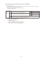
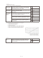
A10 Exhaust Gas Temperature High
Error detection method
During engine operation (complete combustion), when the exhaust gas temperature ≥ 130°C continuously for 10
seconds, the engine is stopped momentarily and an error flag is set.
An Exhaust Gas Temp. High error is assumed when this flag has shut down the engine once.
Troubleshooting
1
Exhaust gas
temperature
1-1
Measure actual exhaust gas temperature. Is it high?
2
Check wiring and
thermistor
2-1
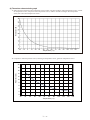
Measure exhaust gas temperature sensor resistance. (See “5. Reference Document” for
thermistor characteristics.)
3
Check coolant
amount
3-1
Check for any disconnected hose. Disconnected?
● For board and Electrical Wiring Diagram, see Chapter 6.
• Outdoor main board: page VI-2
• Outdoor power board: page VI-3
• Converter board: VI-4
• Indoor control board for DC motor models: page VI-5
• Indoor control board for AC motor models: page VI-6
• Outdoor Unit Electrical Wiring Diagram: page VI-7
Ⅳ- 14
Yes
1-2
No
Replace exhaust gas
heat exchanger
Yes
Repair
No
1-1
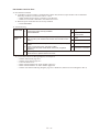
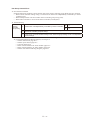
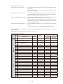
A11 Engine Oil Level Error
Error detection method
● An Engine Oil Level Error has occurred when the oil level switch does not go on after 60 minutes of oil
pump operation with the oil level L switch in Off position (low level) and the engine is off.
Troubleshooting
1
Sub oil pan
2
Communication
hose/Equalizer
hose
3
Oil level low float
switch (OLSL)
4
Check wiring
Yes
3-1
No
2-1
Yes
3-1
No
Repair
Yes
Replace float switch.
3-1
Operating properly? Remove float switch (OLSL)
and check conduction when raising and lowering on
tester.
* Oil level low when float is down (conducting)
No
4-1
4-1
Any broken wires or poor connections between the
outdoor main board connector 4P (black) CN029 No.
3/4 to OLSL?
Yes
Repair
No
Replace outdoor main
board
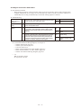
1-1
Proper oil level?
2-1
Pinched/clogged/trapped communication hose or
equalizer hose?
● For work procedure for replacing outdoor main board, see “5. Reference Document”.
● For board and Electrical Wiring Diagram, see Chapter 6.
• Outdoor main board: page VI-2
• Outdoor power board: page VI-3
• Converter board: VI-4
• Indoor control board for DC motor models: page VI-5
• Indoor control board for AC motor models: page VI-6
• Outdoor Unit Electrical Wiring Diagram: page VI-7 * Reference (Electrical Wiring Diagram C - D-6)
•1-1
Oil tank, top view
Storage side
Tank side
Ⅳ- 15
A12 Throttle (Step Motor) Error
A12 Throttle (Stepping Motor) Failure
Abnormality
Error
detectiondetection
method method
c
Whenperforming
performing forced
forced self-diagnosis
2 in
thethe
self-diagnosis
mode,
whenwhen
the throttle
is not is
operating
• • When
self-diagnosismode
mode
2 in
self-diagnosis
mode,
the throttle
not operating
properly,the
theengine
engine is stopped
properly,
stoppedand
andananabnormality
error flag isflag
set.is set.
Whenthe
thereason
reason for engine
abnormality
occurring
time.
When
engineshutdown
shutdownisisthis
this
error flag,flag,
occurring
oneone
time.
Anerror
abnormality
is determined
engine
complete
combustion,
revolution
speedand
andactual
actual
• • An
is determined
when, when,
duringduring
engine
complete
combustion,
thethe
setset
revolution
speed
revolutionspeed
speed differ widely
times
in 1inhour.
(Difference
of ±100
revolutions
duringduring
stable
revolution
widelyfor
for55consecutive
consecutive
times
1 hour.
(Difference
of ±100
revolutions
revolution)
stablerevolution)
* This
can only
be reset
from
outdoor
control
board.
* This
can only
be reset
from
thethe
outdoor
main
board.
Troubleshooting
Troubleshooting
d
1
Wiring
2
Mixer
1-1
2-1
2-2
Any poor connection/contact or broken wires for step
motor (throttle) wiring and connector? (Wiring from
control board connector 6P (black) CN066 to relay
connector 6P-2 (white))
Does the step motor (throttle) coil resistance measure
about 120:? (Disconnect relay connector 6P-2, and
measure between No. 1 (red) and No. 2/No. 3, and
between No. 4 (orange) and No. 5/No. 6.)
When turning power ON (during positioning), is about
DC4V applied respectively across control board connector 6P (black) CN066 No. 1 (+) and No. 2 (–)/No. 3 (–),
and across No. 4 (+) and No. 5 (–)/No. 6 (–)?
● For board and Electrical Wiring Diagram, see Chapter 6.
• Outdoor main board: page VI-2
• Outdoor power board: page VI-3
• Converter board: VI-4
• Indoor control board for DC motor models: page VI-5
• Indoor control board for AC motor models: page VI-6
• Outdoor Unit Electrical Wiring Diagram: page VI-7
Ⅳ- 16
Yes
Repair wiring
No
2-1
Yes
2-2
No
Replace mixer
Yes
Replace mixer
No
Replace control
board
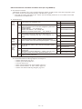
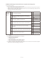
A14 Engine Oil Pressure Switch Error
Error detection method
• When starting the engine, if the oil pressure switch is ON for 6 seconds or more (contact closed) before
complete combustion, an error flag is set. An abnormal stop results on the first occurrence. However, if
turned OFF, the error flag is automatically reset and the starting sequence continues.
Troubleshooting
1
Engine internal
pressure
1-1
Does the error clear when removing the engine head
cover oil cap or the sub oil pan cap?
2
Hose
2-1
Check for pinched or clogged hoses: Engine to sub oil pan connection hose, blowby
hose, and equalizer hose.
3-1
Does this recur even when disconnecting the wiring
connected to the oil pressure switch? (Note: Never
allow the disconnected wiring to touch the frame or
engine.)
3
Wiring
3-2
Is there a ground fault in wiring between the outdoor
main board connector 2P (red) CN012 and the oil
pressure switch? (Remove the wiring between the
connector and the oil pressure switch and measure
resistance between wiring and the engine.
Yes
2-1
No
3-1
Yes
3-2
No
Replace oil pressure
switch
Yes
Repair wiring
No
Replace outdoor main
board
● For work procedure for replacing outdoor main board, see “5. Reference Document”.
● For board and Electrical Wiring Diagram, see Chapter 6.
• Outdoor main board: page VI-2
• Outdoor power board: page VI-3
• Converter board: VI-4
• Indoor control board for DC motor models: page VI-5
• Indoor control board for AC motor models: page VI-6
• Outdoor Unit Electrical Wiring Diagram: page VI-7
• 3-2
With oil pressure: DC0V
No oil pressure: DC12V
Ⅳ- 17
A15 Starter Power Source Output Short Circuit
A15 Starter Power Output Short Circuit
Abnormality detection method
Error
Whendetection
the startermethod
power primary current meets the following conditions, an abnormality is determined upon 5 consecuWhen
the
starter in
power
primary current meets the following conditions, an error is determined upon 5
1 hour.
tive occurrences
consecutive
• Not during cranking: When 40A or more is detected for 0.1 second or more
occurrences
in cranking:
1 hour. When 26A or more is detected for 0.2 second or more
• Not during
Not during
during cranking:
forfor
5.00.1
second
or more
•• Not
cranking:When
When3.8A
40Aorormore
moreis isdetected
detected
second
or more
The starter
powerWhen
source26A
magnet
switch
operation
as follows.
•Note
Not1)during
cranking:
or more
is (52S)
detected
for 0.2issecond
or more
• 52S
turnscranking:
ON upon When
operation
signal
input.isIfdetected
no abnormalities
occur thereafter
• Not
during
3.8A
or more
for 5.0 second
or more (A15, A16, A17), this stays ON,
turns
OFFpower
upon stop
signal
input.switch (52S) operation is as follows.
Note 1)and
The
starter
source
magnet
Turnsturns
OFFON
when
abnormality
•• 52S
upon
operationoccurs.
signal input. If no abnormalities occur thereafter (A15, A16, A17), this stays
ON,and turns OFF upon stop signal input.
• Turns OFF when error occurs.
Troubleshooting
4ROUBLESHOOTING
3TARTERPOWER
SOURCE
$#CURRENT
3TARTER
2EOCCURSEVENWHENDISCONNECTINGTHETWOWIRESFROM
THESTARTERPOWERSOURCETERMINALS
2EOCCURSEVENAFTERDISCONNECTINGCONTROLBOARDCON
NECTOR0YELLOW#.)GNOREABNORMALITY!IFIT
OCCURS
)SEITHEROFTHETWOWIRESFROMTHESTARTERPOWERSOURCE
TERMINALTOTHESTARTERSHORTCIRCUITEDGROUNDFAULTED
ORMISROUTED
9ES
.O
9ES
.O
9ES
.O
2EPLACECONTROLBOARD
2EPLACESTARTER
POWERSOURCE
2EPAIRREPLACE
WIRING
2EPLACESTARTER
●室外メイン基板交換時の作業手順については、
『5.参考資料』の項を参照してください。
● For work procedure for replacing outdoor main
board, see “5. Reference Document”.
●基板および電気配線図は、6
章を参照してください。
● For board and Electrical Wiring
Diagram, see Chapter 6.
・• 室外メイン基板:Ⅵ-2ページ
Outdoor main board: page VI-2
・• 室外パワー基板:Ⅵ-3ページ
Outdoor power board: page VI-3
・• DC
モーター機種用室内コントロール基板:Ⅵ-4ページ
Converter
board: VI-4
・• AC
モーター機種用室内コントロール基板:Ⅵ-5ページ
Indoor
control board for DC motor models: page VI-5
・• 室外ユニット電気配線図:Ⅵ-6ページ
*参照(電気配線図
C~D-1~2)
Indoor control board for AC motor models: page
VI-6
• Outdoor Unit Electrical Wiring Diagram: page VI-7 *Reference (Electrical Wiring Diagram C-D-1-2)
•1-1,2-1
• 1-1, 2-1
2P-18 (black)
2P-17 (white)
(-)
(+)
Ⅳ- 18
A16 Starter Lock
Error detection method
• During cranking, a Starter Locked error is assumed when any of the following conditions occur 5 times in
1 hour: the starter power primary current meets the following condition, no revolution pulse is detected, no
input from the crank angle sensor, no input from the ?cam? angle sensor.
• When 32A or more is detected for 1.0 second or more
Troubleshooting
1) Check starter
1
Starter
1-1
Check for starter lock (If there is no starter lock (includes engine and compressor) replace the
outdoor main board)
● For work procedure for replacing outdoor main board, see “5. Reference Document”.
2) Temporarily remove the compressor drive belt, and check the following rotating parts for locking.
(See Periodic Inspection and Parts Replacement Manual for installing and removing compressor drive belt)
2
Compressor
3
Engine
Yes
3-1
No
Replace
compressor
2-1
Rotates by hand with some resistance?
3-1
Temporarily remove ignition plugs from all cylinders.
Can the engine crank be rotated? (To rotate the crankshaft, follow the procedure in the
Periodic Inspection and Parts Replacement Manual.)
Replace engine if the engine crankshaft does not rotate.
● For board and Electrical Wiring Diagram, see Chapter 6.
• Outdoor main board: page VI-2
• Outdoor power board: page VI-3
• Converter board: VI-4
• Indoor control board for DC motor models: page VI-5
• Indoor control board for AC motor models: page VI-6
• Outdoor Unit Electrical Wiring Diagram: page VI-7
Ⅳ- 19
A17 CT Error (Starter Current Detection Failure)
Error detection method
When the starter power primary current meets the following conditions, an error is determined upon 5
occurrences in 1 hour.
• During cranking: With no detection of starter current, and with revolution speed pulse detected, when 5
seconds pass during cranking or when engine attains complete combustion.
Troubleshooting
1
CT1
(Current sensor
1)
2
Starter power
source
1-1
Does the wiring from the starter power source magnet Yes
switch (52S) terminal No. 1 pass through CT1 (current
No
sensor)?
1-2
1-2
Use a clamp meter on the R-phase wiring of the
starter power source to measure the current during
cranking. Was the current 5A or more?
Yes
1-3
No
2-1
1-3
Yes
Is there a voltage of AC 0.5V or more between
outdoor main board connector 3P (yellow) CN063 No.
1 and No. 3 during cranking?
No
2-1
Broken wire or poor contact in wiring for R and T
phases of starter power source?
Repair wiring
Replace outdoor main
board
Replace current sensor 1
Yes
Repair wiring
No
Replace starter power
source
● For work procedure for replacing outdoor main board, see “5. Reference Document”.
● For board and Electrical Wiring Diagram, see Chapter 6.
• Outdoor main board: page VI-2
• Outdoor power board: page VI-3
• Converter board: VI-4
• Indoor control board for DC motor models: page VI-5
• Indoor control board for AC motor models: page VI-6
• Outdoor Unit Electrical Wiring Diagram: page VI-7* Reference (Electrical Wiring Diagram C - D-1 - 2)
Ⅳ- 20
A19 Low Coolant Temperature
Error detection method
• When the coolant temperature does not exceed 60 C during engine operation (complete combustion) , the
engine stops momentarily. (The time varies between 30 to 60 minutes depending on temperature.)
An emergency shutdown occurs when the engine has stopped twice due to this error.
The cumulative number of times is reset when the coolant maintains a temperature of 60 C or more or
exceeds 85 C.
Troubleshooting
1
Main unit
1-1
Remove the electric cooler three-way valve and check whether it is locked.
Check power initialization, current output and actual valve operation.
→ Repair or replace the three-way valve.
● For board and Electrical Wiring Diagram, see Chapter 6.
• Outdoor main board: page VI-2
• Outdoor power board: page VI-3
• Converter board: VI-4
• Indoor control board for DC motor models: page VI-5
• Indoor control board for AC motor models: page VI-6
• Outdoor Unit Electrical Wiring Diagram: page VI-7
Ⅳ- 21
A20 High Coolant Temperature
Error detection method
When the coolant temperature ≥ 100°C continuously for 2 seconds during engine operation (complete
combustion), the engine is shut down and an error flag is set.
A Coolant Temp. High error is assumed when this flag has shut down the engine 5 consecutive times.
Troubleshooting
1
Pump
rotation
2
Coolant
circuit
1-1 Is the coolant pump rotating during operation?
2-1
Are the three-way electric coolant valve and the electric cooler threeway valve at the engine outlet operating properly?
2-2 Any signs of coolant discharge from the reserve tank?
2-3 Is there air in the coolant?
2-4 Is coolant leaking or seeping from the coolant hose?
4
Check
sensor
3-1
Disconnect the coolant temperature sensor relay connector 2P-12
(green) and measure the resistance value. Measure the surface
temperature and compare. (See “5. Reference Document” for
thermistor characteristics.)
3-2
After resetting the error and operating again, measure the surface
temperature of the coolant circuit. Does the temperature increase?
3-3 Is there water etc. on relay connector 2P-8 (green)?
Yes
2-1
No
See A22
Yes
2-2
No
Repair or replace the
three-way valve.
Yes
2-4
No
2-3
Yes
Discharge air
No
3-1
Yes
Repair, then discharge
air
No
Discharge air
OK
3-2
NG
Replace coolant
temperature sensor
Yes
Reinvestigate
No
3-3
Yes
Repair
No
3-4
3-4 If A20 recurs , replace the outdoor main board.
● For work procedure for replacing outdoor main board, see “5. Reference Document”.
● For board and Electrical Wiring Diagram, see Chapter 6.
• Outdoor main board: page VI-2
• Outdoor power board: page VI-3
• Converter board: VI-4
• Indoor control board for DC motor models: page VI-5
• Indoor control board for AC motor models: page VI-6
• Outdoor Unit Electrical Wiring Diagram: page VI-7
* Reference(Electrical Wiring Diagrams A - B-3: coolant pump)
(Electrical Wiring Diagrams D - E: sensor)
● 2-1
• Three-way electric coolant valve and electric cooler three-way valve inspection
1) Operate engine, and measure the surface temperature of tubing flowing to the 2F outdoor heat exchanger.
2) Confirm that coolant temperature is rising, and that coolant is flowing toward 2F.
● 2-3
• First opened: 70°C Fully open: 80°C
Air discharge hose should not emit large amounts of bubbles.
"Engine discharge part (coolant sensor attachment)
Air bleed cock: E120 and 150 types"
Tubing after engine outlet (before wax valve) Air bleed cock: 190 and 240 types
● 3-1
• Coolant temperature sensor resistance value (See thermistor characteristics chart for details.)
40°C:1.2kΩ
50°C:879Ω
60°C:642Ω
70°C:477Ω
80°C:361Ω
90°C:227Ω
100°C:216Ω
Ⅳ- 22
A21 Coolant Level Error
Error detection method
• The start-up sequence or engine operation is halted and an error flag thrown if the coolant level switch is
off for a 5-second interval during engine start-up (maximum of 3 minutes) or engine operation (complete
combustion).
A Coolant Level Trouble is assumed when the error flag has stopped the engine 5 consecutive times in 1 hour
(at startup 1 time).
• Coolant level (float) switch turns off when the remainder in the reserve tank reaches 0.5 liters.
Troubleshooting
1
Check coolant
level
1-1
Is there coolant in the reserve tank?
2
Check for coolant
leaks
2-1
Any external signs of coolant leaks? Check visually.
3
Check float
switch
2-2
Any coolant in the oil pan?
2-3
Remove drain hose for exhaust gas heat exchanger,
and operate pump → Does the drain emit coolant?
3-1
Is the voltage between outdoor main board connector
3P (white) CN037 No. 1 and No. 3 0 V DC?
3-2
Poor connection/contact/crimping or broken wires
in wiring between outdoor main board connector 3P
(white) CN037 and relay connector 3P-5 (white)?
Yes
3-1
No
2-1
Yes
Repair
No
2-2
Yes
Replace engine head or
gasket
No
2-3
Yes
Replace exhaust gas
heat exchanger
No
Refill coolant
Yes
Replace outdoor main
board
No
3-2
Yes
Repair wiring
No
Replace float switch
● For work procedure for replacing outdoor main board, see “5. Reference Document”.
● For board and Electrical Wiring Diagram, see Chapter 6.
• Outdoor main board: page VI-2
• Outdoor power board: page VI-3
• Converter board: VI-4
• Indoor control board for DC motor models: page VI-5
• Indoor control board for AC motor models: page VI-6
• Outdoor Unit Electrical Wiring Diagram: page VI-7
•2-1
Visually inspect all portions of the coolant system while stopped
Any coolant leaks, or evidence of coolant leaks? Also, any water leaks or hose leaks when circulating water
and activating pump?
Use “water circulation” on No. 4 trial operation/forced settings menu. Press the set key, which lights and
operates the coolant pump. Press again to stop the pump and turn off the key light. (Displays “ Pump”)
1) Hoses and connections
2) Flange connections
3) Threaded connections
4) Tubing/welds
•2-2
Collect oil from oil pan
Emulsification → Mixed
No emulsification → Not mixed
• 3-1
With float switch ON: DC0V
With float switch OFF: DC5V
Ⅳ- 23
A22 Coolant Pump Error
Error detection method
When the coolant pump rotation and drive meet the following conditions, an error is determined on the first
occurrence.
• When coolant pump rotation is not detected upon startup.
• When coolant pump rotation does not increase.
• When coolant pump rotation is too high.
• When overcurrent is detected in the coolant pump circuit.
Troubleshooting
1
Coolant
pump
1-1
Any coolant pump locking, broken wires, poor contact, or short
circuits?
(coil resistance should be around 14-18Ω for each phase.)
1-2
Replace power board and keep under observation.
If A22 reoccurs, replace coolant pump.
Yes
Replace coolant
pump
No
1-2
● For board and Electrical Wiring Diagram, see Chapter 6.
• Outdoor main board: page VI-2
• Outdoor power board: page VI-3
• Converter board: VI-4
• Indoor control board for DC motor models: page VI-5
• Indoor control board for AC motor models: page VI-6
• Outdoor Unit Electrical Wiring Diagram: page VI-7 *Reference (Electrical Wiring Diagram A-B-3)
Ⅳ- 24
A23 Crankshaft Angle Sensor Error
A24 Camshaft Angle Sensor Error
Error detection method
When input from the sensor meets the following conditions, an error is determined upon 5 consecutive
occurrences in 1 hour.
• When starter current was detected during cranking, but crank angle sensor input is not detected for 2
continuous seconds.
• When starter current was detected during cranking, but cam angle sensor input is not detected for 3
continuous seconds.
Troubleshooting
1
Crank angle
sensor trouble
2
Cam angle
sensor trouble
1-1
Does the starter operate?
1-2
Check starter S terminal for short circuit or ground
fault, and starter B terminal for broken wire.
Yes
1-3
No
1-2
OK
Replace starter
NG
Repair wiring
Yes
Repair wiring
1-3
Poor connection or broken wire in crank angle sensor
wiring?
No
1-4
Replace outdoor main board.
If NG, replace sensor.
2-1
Poor connection or broken wire in cam angle sensor
wiring?
2-2
1-4
Yes
Repair wiring
No
2-2
Replace outdoor main board.
If NG, replace sensor.
● For work procedure for replacing outdoor main board, see “5. Reference Document”.
● For board and Electrical Wiring Diagram, see Chapter 6.
• Outdoor main board: page VI-2
• Outdoor power board: page VI-3
• Converter board: VI-4
• Indoor control board for DC motor models: page VI-5
• Indoor control board for AC motor models: page VI-6
• Outdoor Unit Electrical Wiring Diagram: page VI-7 * Reference (Electrical Wiring Diagram B - F-1 - 2)
Ⅳ- 25
A25 Clutch Error
Error detection method
A Clutch Error fault is detected when clutch coil temperature or clutch 2 coil temperature is 110 C or more for up
to 1 minute.
Error is detected with one occurrence.
Troubleshooting
*The compressor uses a twin clutch specification. Inspect both clutch 1 and clutch 2.
1
Compressor lock
1-1
Rotate the compressor pulley by hand while stopped, Yes
to check for compressor lock. Locked?
(Both clutch 1 and clutch 2 are off, so be sure to turn No
the center of the pulley and not just the perimeter.)
Use a contact thermometer to measure the
temperature of the back of the pulley. Is this
temperature nearly identical (within 10 C) to that of
clutch 1 and clutch 2 coil of the outdoor main board?
OK
Investigate further
2-1
NG
2-2
Is there a ground fault or short circuit in wiring
between outdoor main board connector 2P (blue)
CN060 and 2P (yellow) CN064 and their respective
clutch coil sensors.
Yes
Repair wiring
No
Replace clutch coil
sensor
2
Clutch coil sensor
2-2
Replace compressor
2-1
● For board and Electrical Wiring Diagram, see Chapter 6.
• Outdoor main board: page VI-2
• Outdoor power board: page VI-3
• Converter board: VI-4
• Indoor control board for DC motor models: page VI-5
• Indoor control board for AC motor models: page VI-6
• Outdoor Unit Electrical Wiring Diagram: page VI-7
CL2 (clutch 2)
CL (clutch)
•2-1
See Chapter 5 for procedure to view clutch and clutch 2 coil temperature on the outdoor main board.
Ⅳ- 26
A26 Flameout Error
Error detection method
• An error is determined when the engine revolution speed fluctuates widely during engine operation. The
engine is stopped and an error flag is set.
A flameout error is assumed when this flag has shut down the engine 5 consecutive times in 1 hour.
Troubleshooting
1
Ignition system
error
2
Engine unit error
3
Fuel regulating
system error
Yes
1-2
No
1-3
OK
2-1
NG
Adjust timing
Yes
Repair wiring
No
1-4
Yes
1-5
No
Replace ignition plug
1-1
Are sparks emitted properly?
1-2
Proper ignition timing?
1-3
Any poor connection/contact/crimping and broken
wires in wiring between the outdoor main board
connector 6P (white) CN010, 6P (black) CN011 and
each IG coil (igniter)?
1-4
Ignition plug working properly?
1-5
Try replacing the IG coil (igniter). If fault persists after replacement, replace the outdoor
main board.
2-1
Measure compression (See A06 5-1).
2-2
Wash valve and adjust valve clearance. If still NG, replace engine head.
3-1
Check operation of fuel gas regulating valve and
throttle (step motor). Operating properly?
3-2
Inspect zero governor. Operating properly?
3-3
Air intake occurring? Check rubber plug on intake manifold, etc.
OK
3-1
NG
2-2
Yes
3-2
No
Replace
Yes
3-3
No
Restore
● For work procedure for replacing outdoor main board, see “5. Reference Document”.
● For board and Electrical Wiring Diagram, see Chapter 6.
• Outdoor main board: page VI-2
• Outdoor power board: page VI-3
• Converter board: VI-4
• Indoor control board for DC motor models: page VI-5
• Indoor control board for AC motor models: page VI-6
• Outdoor Unit Electrical Wiring Diagram: page VI-7
•1-2
1-2 See Chapter 5 for timing adjustment.
Ⅳ- 27
A27 Catalyst Temperature Error (for only models with catalyst option)
Error detection method
• When a catalyst temperature exceeding 700°C is detected continuously for 10 seconds during engine
operation, the engine is stopped and an error flag is set.
A Catalyst Temp. Trouble is assumed when this flag has shut down the engine 5 consecutive times in 1 hour.
Troubleshooting
1
Unit error
1-1
Check the wiring and connectors. Everything OK?
1-2
Thermistor operating properly?
1-3
Inspect ignition timing. Everything OK?
Yes
1-2
No
Repair wiring
OK
1-3
NG
Replace thermistor
Yes
Replace outdoor
main board
No
Adjust
● For work procedure for replacing outdoor main board, see “5. Reference Document”.
● For board and Electrical Wiring Diagram, see Chapter 6.
• Outdoor main board: page VI-2
• Outdoor power board: page VI-3
• Converter board: VI-4
• Indoor control board for DC motor models: page VI-5
• Indoor control board for AC motor models: page VI-6
• Outdoor Unit Electrical Wiring Diagram: page VI-7
•1-2 Thermistor resistor values
100°C
96.0KΩ
200°C
13.5KΩ
300°C
3.3KΩ
400°C
1.15KΩ
500°C
514Ω
600°C
268Ω
650°C
198Ω
700°C
151Ω
750°C
122Ω
800°C
98Ω
• 1-3 See Chapter 5 for timing adjustment.
Ⅳ- 28
A28 Generator Error (for only G POWER W MULTI)
Error detection method
Generator Error is assumed when an error occurs in the generator.
• When broken wires in generator wiring has resulted in an open phase.
• When a short-circuit has occurred in generator wiring or inside it.
• When a converter circuit is damaged.
Troubleshooting
1
Generator
2
Converter
board
1-1
2-1
Any locking, broken wires, poor contact, short circuits (rare
short-circuit) in the generator? (OK if coil resistance between
wires is about 0.1 - 0.5 Ω)
Do LED5 and LED6 flash on converter 1 or 2?
● For board and Electrical Wiring Diagram, see Chapter 6.
• Outdoor main board: page VI-2
• Outdoor power board: page VI-3
• Converter board: VI-4
• Indoor control board for DC motor models: page VI-5
• Indoor control board for AC motor models: page VI-6
• Outdoor Unit Electrical Wiring Diagram: page VI-7
Ⅳ- 29
Yes
Replace the
generator.
No
2-1
OK
Replace converter
1.
NG
Replace converter
2.
A29 Converter Error (for only G POWER W MULTI)
Error detection method
Converter Error is assumed when an error occurs in the converter.
• When wires are broken or short-circuit has occurred in converter elements.
• When a converter circuit is damaged.
• When the TR temperature sensor and generator temperature sensor connectors are not connected to the
converter board.
Troubleshooting
1
Check
converter
2
Check
connectors
of flashing
converter
1-1
2-1
Do LED5 and LED6 flash on converter 1 or 2?
• Are the TR temperature sensor and generator temperature
sensor connectors connected to the converter board?
● For board and Electrical Wiring Diagram, see Chapter 6.
• Outdoor main board: page VI-2
• Outdoor power board: page VI-3
• Converter board: VI-4
• Indoor control board for DC motor models: page VI-5
• Indoor control board for AC motor models: page VI-6
• Outdoor Unit Electrical Wiring Diagram: page VI-7
Ⅳ- 30
Yes
Replace converter
No
Connect connectors
A30 Low Fuel Gas Pressure Error
ErrorFuel
detection
A30
Gas method
Pressure Low
An
error
is
determined
when
the fuel gas supply pressure is less than the setting value during fuel gas valve
� Abnormality
detection
method
operation
(open)
continuously
for 3 the
seconds.
An abnormality is determined when
fuel gas supply pressure is less than the setting value during fuel gas valve
• operation
Pressure(open)
setting:
P
0.4KPa
(gas
low pressure switch contact ON)
continuously for 3 seconds.
• Pressure setting: P � 0.4KPa (gas low pressure switch contact ON)
Troubleshooting
� Troubleshooting
1
Check gas
supply pressure
1-1
1-2
1-3
1-4
Check fuel gas supply pressure.
Is the supply pressure low?
Yes
No
Check gas pressure and tubing
diameter
1-2
When the gas supply pressure is proper, disconnect 3P
(green) CN040 on the control board, and check conduction of the gas low pressure switch.
Conducting?
Check for short-circuiting (or pinching) of fuel gas low
pressure switch wiring.
Any short-circuited wiring (from board to fuel gas low
pressure switch)?
Yes
1-3
No
1-4
Repair/replace
wiring
Replace gas low
No
pressure switch
If the supply pressure is normal and A30 occurs, replace the control board.
● For board and Electrical Wiring Diagram, see Chapter 6.
• Outdoor main board: page VI-2
• Outdoor power board: page VI-3
• Converter board: VI-4
• Indoor control board for DC motor models: page VI-5
• Indoor control board for AC motor models: page VI-6
• Outdoor Unit Electrical Wiring Diagram: page VI-7
III – 43
Ⅳ- 31
Yes
E01 Remote Controller Receive Failure
Error detection method
An error is determined when no incoming communication is received for 3 minutes.
• When 9 or more indoor units are wired into the remoto controller group.
• When inspection (inspection pin) or TEST (test pin) on the indoor control board is short-circuited.
• When the non-volatile memory (EEPROM) is not inserted or has failed upon turning power ON.
• Indoor control board failure
Troubleshooting
1
Auto-address
2
Group control
wiring
3
Indoor control
board
●
●
●
●
1-1
Is auto-addressing complete?
Yes
1-2
No
1-3
OK
1-3
NG
2-1
1-2
Has auto-addressing failed (warning displayed on
outdoor unit)?
1-3
Perform pre-check before auto-addressing. (See “5. Reference Document”)
2-1
Is this indoor unit group-controlled?
2-2
Are any indoor units wired into the remoto controller
group turned OFF?
2-3
Are 9 or more indoor units connected to one remoto
controller group wiring?
2-4
Was the remoto controller group wiring modified
after autoaddressing was complete? Or, were
group settings changed using the remoto controller
properties setting mode?
2-5
No main unit present in remoto controller group wiring --> Repeat auto-addressing.
3-1
Is the inspection pin (CN062/CN071) or TEST pin
(CN064) on the indoor control board short-circuited?
Yes
Eliminate short-circuit
No
3-2
3-2
Is an option board (CN060) or wireless remoto
controller (CN041) connected to the indoor control
board?
Yes
3-3
No
3-5
3-3
Does E01 disappear several minutes after
Yes
disconnecting said connector on the indoor control
board? (When controlling with two remoto controllers
and the wireless remoto controller is the main, set the
No
other remoto controller as the main).
Yes
2-2
No
3-1
Yes
Turn power ON
No
2-3
Yes
Repair wiring
No
2-4
Yes
2-5
No
3-1
3-4
3-5
3-4
Replace the removed option board or wireless remoto controller operating unit, wiring and
all.
3-5
Is the LED (D002) blinking on the indoor control
board?
3-6
Nonvolatile memory (EEPROM) on the outdoor main unit is not inserted, is incorrectly
inserted or is defective --> Correct or replace nonvolatile memory and program it in the
remoto controller properties setting mode.
3-7
Short-circuit or misrouting in indoor unit remoto
controller wiring?
Yes
3-6
No
3-7
Yes
Repair wiring
No
Replace indoor control
board
The designation (/) is used in the table to indicate indoor boards for DC and AC motor models.
There is no TEST pin on the indoor board for AC motor models.
See “5. Reference Document” for checking remoto controller.
For board and Electrical Wiring Diagram, see Chapter 6.
• Outdoor main board: page VI-2
• Outdoor power board: page VI-3
• Converter board: VI-4
• Indoor control board for DC motor models: page VI-5
• Indoor control board for AC motor models: page VI-6
• Outdoor Unit Electrical Wiring Diagram: page VI-7
● See instructions packaged with servicing indoor board for procedure on replacing indoor non-volatile
memory (EEPROM) and replacing indoor control board.
Ⅳ- 32
E02 Remote Controller Transmission Failure
Error detection method
When the remoto controller (controller) itself cannot transmit. Or, when a self-transmitted signal cannot be selfreceived or changes, an error is determined.
• Breakdown of remoto controller itself
Troubleshooting
1
Remoto
controller
group wiring
2
Indoor
control
board
Yes
1-2
No
2-1
1-1
Is this indoor unit group-controlled?
1-2
Any short-circuit or broken wires for remoto controller group link Yes
wiring 1 (white) and 2 (black)?
No
Repair wiring
2-1
2-1
Is an option board (CN060) or wireless remoto controller
(CN041) connected to the indoor control board?
Yes
No
2-4
Yes
2-3
2-2
Does E02 disappear several minutes after disconnecting said
connector on the indoor control board? (When controlling with
two remoto controllers and the wireless remoto controller is the
main, set the other remoto controller as the main).
No
2-4
2-3
Replace the removed option board or wireless remoto controller operating unit, wiring and all.
2-4
Short-circuit or misrouting in indoor unit remoto controller
wiring?
●
●
●
●
2-2
Yes
Repair wiring
No
Replace indoor
control board
The designation (/) is used in the table to indicate indoor boards for DC and AC motor models.
There is no TEST pin on the indoor board for AC motor models.
See “5. Reference Document” for checking remoto controller.
For board and Electrical Wiring Diagram, see Chapter 6.
• Outdoor main board: page VI-2
• Outdoor power board: page VI-3
• Converter board: VI-4
• Indoor control board for DC motor models: page VI-5
• Indoor control board for AC motor models: page VI-6
• Outdoor Unit Electrical Wiring Diagram: page VI-7
● See instructions packaged with servicing indoor board for procedure on replacing indoor control board.
Ⅳ- 33
E03 Indoor Unit Receive Failure from Remote Controller (Central)
Error detection method
1) With indoor unit connected
An error is determined when no transmission is received from the remote controller (central) for 3 minutes,
or when no transmission is received from the central equipment for 15 minutes.
• When transmission had been normal but the remoto controller wiring became broken or misrouted.
• Broken indoor and outdoor operating wiring to central control equipment.
• Only sub remoto controller is set.
• No remoto controller, with central control equipment power OFF.
• No remoto controller, and only sub remoto controller is set.
Troubleshooting
1
Central control
equipment
2
Remoto controller
3
Indoor control
board
1-1
Is central control equipment connected?
1-2
Is the central control equipment power OFF?
Yes
1-2
No
2-1
Yes
Turn power ON
No
1-3
Yes
1-4
No
1-5
1-3
Are all the central control main-sub switches on the
connected central control equipment set to “sub”?
1-4
Of the connected central control equipment, set only the highest-ranking central control
unit to “main”, and set the remaining units to “sub”. Ranking order from high to low: AMY
adapter → intelligent controller → system controller → multi-controller.
1-5
Are any broken indoor and outdoor operating wires
connected to central control equipment? (See “5.
Reference Document”)
2-1
Is this indoor unit group-controlled?
2-2
Any broken wires for remoto controller group link
wiring 1 (white) and 2 (black)?
3-1
Is an option board (CN060) or wireless remoto
controller (CN041) connected to the indoor control
board?
3-2
Does E03 disappear several minutes after
Yes
disconnecting said connector on the indoor control
board? (When controlling with two remoto controllers
and the wireless remoto controller is the main, set the No
other remoto controller as the main).
3-3
Replace the removed option board or wireless remoto controller operating unit, wiring and
all.
3-4
Short-circuit, misrouting, or broken wires in indoor
unit remoto controller wiring?
●
●
●
●
Yes
Repair wiring
No
2-1
Yes
2-2
No
3-1
Yes
Repair wiring
No
3-1
Yes
3-2
No
3-4
3-3
3-4
Yes
Repair wiring
No
Replace indoor control
board
The designation (/) is used in the table to indicate indoor boards for DC and AC motor models.
There is no TEST pin on the indoor board for AC motor models.
See “5. Reference Document” for checking remoto controller.
For board and Electrical Wiring Diagram, see Chapter 6.
• Outdoor main board: page VI-2
• Outdoor power board: page VI-3
• Converter board: VI-4
• Indoor control board for DC motor models: page VI-5
• Indoor control board for AC motor models: page VI-6
• Outdoor Unit Electrical Wiring Diagram: page VI-7
● See instructions packaged with servicing indoor board for procedure on replacing indoor control board.
Ⅳ- 34
•1-4
Central control, main/sub switch
Main: OFF
Sub: ON
Central control, main/sub switch
Main: OFF
Sub: ON
System Controller
Intelligent Controller
Central control, main/sub switch
Main: OFF
Sub: ON
Multi-Controller
Ⅳ- 35
E04 Indoor Unit Receive Failure from Outdoor Unit
Error detection method
After turning power ON, with no transmission from outdoor unit for 3 minutes. Or, an error is determined when
the outdoor unit does not respond.
• Outdoor unit power is OFF.
• With link wiring, when outdoor main board terminal resistor switch (S7) is set to “ON” for several units.
• When turning power ON after completing auto-addressing, when the number of indoor units has changed.
• When indoor unit power is not ON.
• Inspection pin (CN062/CN071) or TEST pin (CN064) on the indoor control board is short-circuited.
• Non-volatile memory (EEPROM) is not inserted when changing indoor board.
• In the remoto controller detailed settings mode, the indoor address is “undetermined”.
• Indoor unit addresses duplicated
• Indoor/outdoor operation wiring is short-circuited or broken.
• Error in the reception circuit on the signal output board (option board)
• Breakdown of outdoor unit
• High voltage (AC200V, etc) applied across indoor/outdoor operation wire circuit
Troubleshooting
1
Power
supply
2
Indoor/
outdoor
operation
wiring
3
Indoor
unit count
4
Indoor
control
board
1-1
Is/was the outdoor unit power OFF?
Yes
Turn power ON and wait
3 minutes
No
1-2
Yes Turn power ON
1-2
Is the indoor unit power OFF?
2-1
Indoor/outdoor operation wiring broken or short-circuited? (See
“5. Reference Document”)
2-2
With link wiring, is the outdoor main board terminal resistor
switch (S010) set to “ON” for several units?
2-3
High voltage (AC200V, etc) applied across indoor/outdoor
operation wire circuit?
3-1
Did the number of indoor units increase or decrease after autoaddressing?
3-2
Perform pre-check before auto-addressing. (See “5. Reference Document”)
3-3
In the remoto controller detailed settings mode, check the
indoor unit address (item code 13). Any undetermined (99) or
duplicated addresses for indoor units?
4-1
Is the inspection pin (CN062/CN071) or TEST pin (CN064) on
the indoor control board short-circuited?
4-2
Is an option board (CN060) or wireless remoto controller
(CN041) connected to the indoor control board?
4-3
Does E04 disappear several minutes after disconnecting said
connector on the indoor control board? (When controlling with
two remoto controllers and the wireless remoto controller is the
main, set the other remoto controller as the main).
4-4
Replace the removed option board or wireless remoto controller operating unit, wiring and all.
4-5
Is the LED (D002) blinking on the indoor control board?
4-6
Nonvolatile memory (EEPROM) on the outdoor main unit is not inserted, is incorrectly inserted
or is defective --> Correct or replace nonvolatile memory and program it in the remoto controller
properties setting mode.
4-7
Is E4 displayed on all remoto controllers for other indoor units
connected to this outdoor unit?
No
Ⅳ- 36
2-1
Yes Repair wiring
No
2-2
Yes Set only one unit to “ON”
No
2-3
Yes 3-2
No
3-1
Yes 3-2
No
3-3
Yes 3-2
No
4-1
Yes Eliminate short-circuit
No
4-2
Yes 4-3
No
4-5
Yes 4-4
No
4-5
Yes 4-6
No
4-7
Yes
Replace outdoor main
board
No
Replace indoor control
board
● The designation (/) is used in the table to indicate indoor boards for DC and AC motor models.
● There is no TEST pin on the indoor board for AC motor models.
● For board and Electrical Wiring Diagram, see Chapter 6.
• Outdoor main board: page VI-2
• Outdoor power board: page VI-3
• Converter board: VI-4
• Indoor control board for DC motor models: page VI-5
• Indoor control board for AC motor models: page VI-6
• Outdoor Unit Electrical Wiring Diagram: page VI-7
● See instructions packaged with servicing indoor board for procedure on replacing indoor non-volatile
memory (EEPROM) and replacing indoor control board.
● See “5. Reference Document” for checking remoto controller.
Ⅳ- 37
E05 Indoor UnitTransmission Faiure to Outdoor Unit
Error detection method
When a self-transmitted signal cannot be self-received, an error is determined.
• Indoor (water heat exchanger unit) control board is defective.
• Outdoor main board terminal resistor switch setting is incorrect.
Troubleshooting
1
Indoor
control
board
1-1
Is the indoor/outdoor operation wiring connected to multiple
outdoor units? (Link wiring?)
1-2
Is the S010 (terminal resistor) switch on one outdoor main board
set to “ON” and the remainder to “OFF”?
1-3
Is the outdoor main board S010 (terminal resistor) switch set to
“OFF”?
1-4
Indoor/outdoor operation wiring broken or short-circuited?
1-5
Replace indoor (water heat exchanger unit) control board
Yes 1-2
No
1-3
Yes 1-4
No
Set only one unit to “ON”
Yes Set to “ON”
No
1-4
Yes Repair wiring
No
1-5
● For board and Electrical Wiring Diagram, see Chapter 6.
• Outdoor main board: page VI-2
• Outdoor power board: page VI-3
• Converter board: VI-4
• Indoor control board for DC motor models: page VI-5
• Indoor control board for AC motor models: page VI-6
• Outdoor Unit Electrical Wiring Diagram: page VI-7
● See instructions packaged with servicing indoor board for procedure on replacing indoor control board.
Ⅳ- 38
E06 Outdoor Unit Receive Failure from Indoor Unit
Error detection method
An error is determined when no indoor unit transmission (response) is received for 3 minutes.
• Indoor unit power is OFF.
• Indoor unit DISP pin (CN063/CN072) is short-circuited.
• Indoor/outdoor operation wiring is short-circuited or broken.
• Indoor unit signal output board (option board) is defective.
Troubleshooting
1
Indoor
power
source
Yes Turn power ON
1-1
Is the indoor unit power OFF?
2
Indoor/
outdoor
operation
wiring
2-1
Indoor/outdoor operation wiring broken or short-circuited? (See
“5. Reference Document”)
3
Indoor
control
board
3-1
Is the DISP pin (CN063/CN071) or inspection pin (CN062/
CN071) on the indoor control board short-circuited?
3-2
Is an option board (CN060) or wireless remoto controller
(CN041) connected to the indoor control board?
3-3
Does E06 disappear several minutes after disconnecting said
connector on the indoor control board? (When controlling with
two remoto controllers and the wireless remoto controller is the
main, set the other remoto controller as the main).
3-4
Replace the removed option board or wireless remoto controller operating unit, wiring and all.
3-5
Indoor control board failure → Replace board
No
2-1
Yes Repair wiring
No
3-1
Yes Eliminate short-circuit
No
3-2
Yes 3-3
No
3-5
Yes 3-4
No
3-5
● The designation (/) is used in the table to indicate indoor boards for DC and AC motor models.
● There is no TEST pin on the indoor board for AC motor models.
● For board and Electrical Wiring Diagram, see Chapter 6.
• Outdoor main board: page VI-2
• Outdoor power board: page VI-3
• Converter board: VI-4
• Indoor control board for DC motor models: page VI-5
• Indoor control board for AC motor models: page VI-6
• Outdoor Unit Electrical Wiring Diagram: page VI-7
● See instructions packaged with servicing indoor board for procedure on replacing indoor control board.
Ⅳ- 39
E07 Outdoor Unit Transmission Failure to Indoor Unit
Error detection method
When a self-transmitted signal cannot be self-received (is mismatched) for 3 minutes, an error is determined.
• Outdoor main board is defective
• Outdoor main board terminal resistor switch setting is incorrect.
Troubleshooting
1
Outdoor
main
board
1-1
"Is the indoor/outdoor operation wiring connected to multiple
outdoor units? (Link wiring?) * Link wiring not available when
water heat exchanger
unit is connected."
1-2
Is the S010 (terminal resistor) switch on one outdoor main board
set to “ON” and the remainder to “OFF”?
1-3
Is the outdoor main board S010 (terminal resistor) switch set to
“OFF”?
1-4
Indoor/outdoor operation wiring broken or short-circuited? (See
“5. Reference Document”)
1-5
Replace outdoor main board
Yes 1-2
No
1-3
Yes 1-4
No
Set only one unit to “ON”
Yes Set to “ON”
No
1-4
Yes Repair wiring
No
1-5
● For work procedure for replacing outdoor main board, see “5. Reference Document”.
● For board and Electrical Wiring Diagram, see Chapter 6.
• Outdoor main board: page VI-2
• Outdoor power board: page VI-3
• Converter board: VI-4
• Indoor control board for DC motor models: page VI-5
• Indoor control board for AC motor models: page VI-6
• Outdoor Unit Electrical Wiring Diagram: page VI-7
Ⅳ- 40
E08 Duplicated Indoor Unit Address Setting
Error detection method
An error is determined when the Indoor unit address is duplicated.
• In the remoto controller detailed settings mode, the indoor address setting is duplicated.
• Several indoor units with no indoor unit address setting have the DISP pin (CN063/CN072) short-circuited.
Troubleshooting
1
Indoor
control
board
Yes Eliminate short-circuit
1-1
Is the DISP pin (CN063/CN072) on the indoor control board
short-circuited?
1-2
Perform pre-check before auto-addressing. (See “5. Reference
Document”) E08 remains after repeating auto-addressing?
1-3
Non-volatile memory (EEPROM) on indoor board is defective → Replace
1-4
To change indoor unit address, instead of the remoto controller detailed settings, use remoto
controller address change mode.
No
1-2
Yes 1-3
No
1-4
● The designation (/) is used in the table to indicate indoor boards for DC and AC motor models.
● For board and Electrical Wiring Diagram, see Chapter 6.
• Outdoor main board: page VI-2
• Outdoor power board: page VI-3
• Converter board: VI-4
• Indoor control board for DC motor models: page VI-5
• Indoor control board for AC motor models: page VI-6
• Outdoor Unit Electrical Wiring Diagram: page VI-7
● See instructions packaged with servicing indoor board for procedure on replacing indoor non-volatile
memory (EEPROM).
Ⅳ- 41
E09 Multiple Main Remoto Controller Units Set
Error detection method
An error is determined when multiple main remoto controllers exist within a remoto controller group.
• Forgot to set a remoto controller “sub” when controlling with two remoto controllers.
• Forgot to set a remoto controller “sub” when controlling with a wireless remoto controller and a wired remoto
controller
Troubleshooting
1
Remoto
controller
1-1
Set one of the two remoto controllers to “Sub”.
● For board and Electrical Wiring Diagram, see Chapter 6.
• Outdoor main board: page VI-2
• Outdoor power board: page VI-3
• Converter board: VI-4
• Indoor control board for DC motor models: page VI-5
• Indoor control board for AC motor models: page VI-6
• Outdoor Unit Electrical Wiring Diagram: page VI-7
● 1-1
Sub remote setup procedure (E type)
Hold down the Change mode and Set buttons for 4 seconds or more.
"Setup", an item code " " and setup data " " appears on the remoto controller LCD.
Use the ▼ / ▲ buttons to switch to " " setup data.
Press the Set button (the setting is completed when flashing changes to steady light)
Press the Inspect button to return to normal remoto controller display.
Wired remoto controller (B type)
Wireless remoto controller
Remote controller address
Remoto controller main
Remote controller sub
Main: OFF
Sub: ON
Remote controller address connector
Ⅳ- 42
E11 Indoor Unit Receive Failure from Signal Output Board
Error detection method
After confirming existence of the signal output board, an error is determined upon no reception from the signal
output board.
• Signal output board is defective.
• Wiring to signal output board is defective.
Troubleshooting
1
Signal
output
board
1-1
Wiring to signal output board (option board) broken or shortcircuited?
1-2
Replace the signal output board (option board) and wiring. Is
E11 displayed again?
Yes Repair wiring
No
1-2
Yes
Replace indoor control
board
No
Replace signal output
board
● For board and Electrical Wiring Diagram, see Chapter 6.
• Outdoor main board: page VI-2
• Outdoor power board: page VI-3
• Converter board: VI-4
• Indoor control board for DC motor models: page VI-5
• Indoor control board for AC motor models: page VI-6
• Outdoor Unit Electrical Wiring Diagram: page VI-7
● See instructions packaged with servicing indoor board for procedure on replacing indoor control board.
Ⅳ- 43
E12 Automatic Address Setting Is in Progress: Automatic Address Setting Start is Prohibited
Error detection method
An error is determined when an auto-addressing startup command is received from another unit during
autoaddressing.
• In a system with multiple outdoor units, with indoor/outdoor operation wiring connected (with link wiring),
an autoaddressing startup command was issued by another unit during auto-addressing.
Troubleshooting
1
Autoaddress
1-1
In a system with multiple outdoor units, with indoor/outdoor operation wiring connected (with
link wiring), an autoaddressing startup command was issued by another unit during autoaddressing.
Wait until current auto-addressing is complete.
● For board and Electrical Wiring Diagram, see Chapter 6.
• Outdoor main board: page VI-2
• Outdoor power board: page VI-3
• Converter board: VI-4
• Indoor control board for DC motor models: page VI-5
• Indoor control board for AC motor models: page VI-6
• Outdoor Unit Electrical Wiring Diagram: page VI-7
Ⅳ- 44
E13 Indoor Unit Transmission Failure to Remoto controller
Error detection method
When a signal transmitted from the indoor unit (water heat exchanger unit) to the remoto controller cannot be
self-received, an error is determined.
• Indoor unit (water heat exchanger unit) control board is defective.
• Short-circuit or broken wires in remoto controller wiring 1 (white) and 2 (black) (with indoor unit connected)
Troubleshooting
1
Indoor
control
board
1-1
Any short-circuit or broken wires in remoto controller wiring 1
(white) and 2 (black)?
1-2
Replace indoor control board.
Yes Repair wiring
No
1-2
● For board and Electrical Wiring Diagram, see Chapter 6.
• Outdoor main board: page VI-2
• Outdoor power board: page VI-3
• Converter board: VI-4
• Indoor control board for DC motor models: page VI-5
• Indoor control board for AC motor models: page VI-6
• Outdoor Unit Electrical Wiring Diagram: page VI-7
● See instructions packaged with servicing indoor board for procedure on replacing indoor control board.
Ⅳ- 45
E15 Automatic Address Alarm (Too Few Units)
Error detection method
An error is determined when the indoor unit count responding to transmission is less than the indoor unit count
set on the outdoor unit. (Also detected apart from auto-addressing.)
• The actual number of indoor units is less than the number of indoor units set on the outdoor unit.
• Connected indoor unit power is OFF
• An indoor unit has a short-circuited inspection pin (CN062/CN071) or TEST pin (CN064) upon power ON.
• High voltage (AC200V, etc) was applied across indoor/outdoor operation wire circuit.
Troubleshooting
1
Power
supply
2
Indoor/
outdoor
operation
wiring
3
Indoor
unit count
4
Indoor
control
board
5
Outdoor
main
board
Yes Turn power ON
1-1
Is the indoor unit power OFF?
2-1
Indoor/outdoor operation wiring broken or short-circuited?
(See “5. Reference Document”)
2-2
High voltage (AC200V, etc) applied across indoor/outdoor
operation wire circuit?
3-1
Did the number of indoor units change after autoaddressing?
Or, was the indoor unit count setting changed on the outdoor
main board?
3-2
Perform pre-check before auto-addressing. (See “5. Reference Document”)
4-1
Is the inspection pin (CN062/CN071) or TEST pin (CN064) on
the indoor control board short-circuited?
4-2
Is an option board (CN060) or wireless remoto controller
(CN041) connected to the indoor control board?
4-3
Does E15 disappear several minutes after disconnecting said
connector on the indoor control board? (When controlling with
two remoto controllers and the wireless remoto controller is the
main, set the other remoto controller as the main).
4-4
Replace the removed option board or wireless remoto controller operating unit, wiring and all.
4-5
Is the LED blinking on the indoor control board?
4-6
Nonvolatile memory (EEPROM) on the outdoor main unit is not inserted, is incorrectly inserted
or is defective --> Correct or replace nonvolatile memory and program it in the remoto controller
properties setting mode.
5-1
On the outdoor main board, use setting No. 10 to set the indoor unit count. Then compare the
indoor unit connection status using No. 9 (indoor unit check), and investigate the unaccounted
indoor unit in detail.
No
●
●
●
●
2-1
Yes Repair wiring
No
2-2
Yes 3-2
No
3-1
Yes 3-2
No
4-1
Yes Eliminate short-circuit
No
4-2
Yes 4-3
No
4-5
Yes 4-4
No
4-5
Yes 4-6
No
5-1
The designation (/) is used in the table to indicate indoor boards for DC and AC motor models.
There is no TEST pin on the indoor board for AC motor models.
See “5. Reference Document” for checking remoto controller.
For board and Electrical Wiring Diagram, see Chapter 6.
• Outdoor main board: page VI-2
• Outdoor power board: page VI-3
• Converter board: VI-4
• Indoor control board for DC motor models: page VI-5
• Indoor control board for AC motor models: page VI-6
• Outdoor Unit Electrical Wiring Diagram: page VI-7
● See instructions packaged with servicing indoor board for procedure on replacing indoor non-volatile
memory (EEPROM) and replacing indoor control board.
* In systems that link wiring systems where a water heat exchanger unit is connected, the state of hot and cold
water may output an Automatic Address Setting Warning.
Should this happen, remove link wiring and set a different address.
Ⅳ- 46
E16 Automatic Address Alarm (Too Many Units)
Error detection method
An error is determined when the indoor unit count (water heat exchanger units) responding to transmission
exceeds the indoor unit count (water heat exchanger units) set on the outdoor unit. (Also detected apart from
autoaddressing.)
• The actual number of indoor units exceeds the number of indoor units set on the outdoor unit (with indoor
unit connected).
Troubleshooting
1
Autoaddress
1-1
Perform pre-check before auto-addressing. (See “5. Reference Document”)
● For board and Electrical Wiring Diagram, see Chapter 6.
• Outdoor main board: page VI-2
• Outdoor power board: page VI-3
• Converter board: VI-4
• Indoor control board for DC motor models: page VI-5
• Indoor control board for AC motor models: page VI-6
• Outdoor Unit Electrical Wiring Diagram: page VI-7
Ⅳ- 47
E18 Group Control Wiring Communication Failure
Error detection method
When remoto controller group control main unit cannot communicate with sub unit. An error is determined when
the remoto controller group control sub unit has not communicated with the main unit for 3 minutes.
• An indoor unit within group control is not powered ON.
• Inspection pin (CN062/CN071) or TEST pin (CN064) is short-circuited on an indoor unit within group
control.
• Indoor unit DISP pin (CN063/CN072) is short-circuited on a sub indoor unit within group control.
• Remoto controller group wiring is broken.
• Multiple indoor units within group control are set as “main.”
• An indoor unit within group control is set as “independent.”
Troubleshooting
1
Indoor
unit
2
Remoto
controller
group
Wiring
3
Indoor
control
board
Yes Turn power ON
1-1
Is the indoor unit power OFF?
1-2
Is the inspection pin (CN062/CN071) or TEST pin (CN064) or
DISP pin (CN063/CN072) on the indoor control board shortcircuited?
2-1
Remoto controller group wiring broken?
2-2
In the remoto controller detailed settings mode, check the
group settings (item code 14). Multiple main units (1), or any
independent (0) settings?
2-3
Remoto controller group wiring routed as intended?
2-4
Repeat auto-addressing process.
2-5
After repairing remoto controller group wiring, repeat auto-addressing process.
3-1
Is an option board (CN060) or wireless remoto controller
(CN041) connected to the indoor control board?
3-2
Does E18 disappear several minutes after disconnecting said
connector on the indoor control board? (When controlling with
two remoto controllers and the wireless remoto controller is the
main, set the other remoto controller as the main).
3-3
Replace the removed option board or wireless remoto controller operating unit, wiring and all.
3-4
Replace indoor control board
No
●
●
●
●
1-2
Yes Eliminate short-circuit
No
2-1
Yes Repair wiring
No
2-2
Yes 2-3
No
3-1
2-4
2-5
Yes 3-2
No
3-4
Yes 3-3
No
3-4
The designation (/) is used in the table to indicate indoor boards for DC and AC motor models.
There is no TEST pin on the indoor board for AC motor models.
See “5. Reference Document” for checking remoto controller.
For board and Electrical Wiring Diagram, see Chapter 6.
• Outdoor main board: page VI-2
• Outdoor power board: page VI-3
• Converter board: VI-4
• Indoor control board for DC motor models: page VI-5
• Indoor control board for AC motor models: page VI-6
• Outdoor Unit Electrical Wiring Diagram: page VI-7
● See instructions packaged with servicing indoor board for procedure on replacing indoor control board.
Ⅳ- 48
E20 No Indoor Unit in Automatic Address Setting
Error detection method
An error is determined when an indoor unit is not recognized at auto-addressing start up or upon turning the
outdoor unit power ON.
• Indoor unit address is not properly assigned.
• Indoor unit power is OFF.
Troubleshooting
1
Power
supply,
wiring
Yes 1-2
1-1
Indoor unit address properly assigned?
1-2
Is the indoor unit power ON?
1-3
The indoor/outdoor control wire may not be connected between the indoor unit and outdoor unit.
Check wiring connections on indoor/outdoor control wire.
No
Set address
Yes 1-3
No
● For board and Electrical Wiring Diagram, see Chapter 6.
• Outdoor main board: page VI-2
• Outdoor power board: page VI-3
• Converter board: VI-4
• Indoor control board for DC motor models: page VI-5
• Indoor control board for AC motor models: page VI-6
• Outdoor Unit Electrical Wiring Diagram: page VI-7
Ⅳ- 49
Turn power ON
E21 Outdoor Main Board Error
Error detection method
External noise may interfere with microprocessor operation.
Troubleshooting
1
Outdoor
main
board
2
Noise
1-1
This may occur directly after resetting other faults, perform the reset on the outdoor main board.
1-2
This is possibly caused by random noise, turn off the outdoor power supply. Then turn it back on
and keep it under observation.
If the fault recurs, replace the outdoor main board and outdoor power board.
Yes Noise countermeasures
2-1
Is a noise source near the outdoor unit?
No
Replace the outdoor main
board and outdoor power
board.
● For work procedure for replacing outdoor main board, see “5. Reference Document”.
● For board and Electrical Wiring Diagram, see Chapter 6.
• Outdoor main board: page VI-2
• Outdoor power board: page VI-3
• Converter board: VI-4
• Indoor control board for DC motor models: page VI-5
• Indoor control board for AC motor models: page VI-6
• Outdoor Unit Electrical Wiring Diagram: page VI-7
Ⅳ- 50
E22 Outdoor Main Board Sensor Error
Error detection method
The voltage in the input circuits of the outdoor main board sensor is unstable and fluctuates.
Troubleshooting
1
Outdoor
main board
1-1
Turn OFF the outdoor unit, then turn ON and observe.
If the error recurs, replace outdoor main board.
● For board and Electrical Wiring Diagram, see Chapter 6.
• Outdoor main board: page VI-2
• Outdoor power board: page VI-3
• Converter board: VI-4
• Indoor control board for DC motor models: page VI-5
• Indoor control board for AC motor models: page VI-6
• Outdoor Unit Electrical Wiring Diagram: page VI-7
Ⅳ- 51
E24 Communication Failure between Outdoor Units (for only W MULTI)
Error detection method
An Outdoor Communication Unit Failure is assumed when communications between outdoor units in the same
refrigerant system are not possible for 2 minutes.
• An outdoor unit address has not been properly assigned.
• Outdoor unit power is OFF.
Troubleshooting
1
Power
supply,
wiring
Yes 1-2
1-1
Have outdoor unit addresses and outdoor unit and number of
connected outdoor units been properly entered?
1-2
Have all outdoor units in the same system been turned on?
1-3
The indoor/outdoor operation wiring may not be connected between the indoor unit and outdoor
unit.
Check wiring connections on indoor/outdoor operation wiring.
● For board and Electrical Wiring Diagram, see Chapter 6.
• Outdoor main board: page VI-2
• Outdoor power board: page VI-3
• Converter board: VI-4
• Indoor control board for DC motor models: page VI-5
• Indoor control board for AC motor models: page VI-6
• Outdoor Unit Electrical Wiring Diagram: page VI-7
Ⅳ- 52
No
Enter the data correctly.
Yes 1-3
No
Turn power ON
E26 Inconsistencies in Number of Outdoor Units (for only W MULTI)
Error detection method
A Mismatch of Outdoor Unit Count is assumed when the number of outdoor units in the same refrigerant system
(No. 10 first on) does not match made setting in a W MULTI (*) system.
* A unit with an outdoor unit address (No. 10 First sub) of something other than "0" in an outdoor main board
is identified as a W MULTI unit.
Troubleshooting
1
Check
board
setting
2
Check
wiring
3
Check
the power
supply
and
wiring
Yes 1-2
1-1
Is the outdoor unit a W MULTI unit?
Yes 2-1
1-2
Have the system address, outdoor unit address and number of
connected outdoor units for the same refrigerant system been
properly entered?
•System address ... No. 10 First out
•Outdoor unit address ...No. 10 First sub
•Number of connected outdoor units ...No. 10 First on
1-3
Is the outdoor unit address set to "0"?
* For systems other than W MULTI, be sure to set "0."
A system set to something other than "0" is recognized as W
MULTI.
Yes 3-3
2-1
Is the wiring (indoor/outdoor operation wiring) between W
MULTI outdoor units in the same refrigerant system connected?
3-1
Are all W MULTI outdoor units in the same refrigerant system
turned on?
3-2
Is the S010 (terminal resistor) switch on the outdoor main board Yes 3-3
correctly set?
* Regardless of system addresses, 1 outdoor unit in the same
No Enter the data correctly.
link wiring must be set to "Short" (terminal resistor "on").
3-3
Replace outdoor main board
No
No
No
1-3
Enter the data correctly.
Set to "0."
Yes 3-1
No
Repair wiring.
Yes 3-2
No
Turn power ON
● For work procedure for replacing outdoor main board, see “5. Reference Document”.
● For board and Electrical Wiring Diagram, see Chapter 6.
• Outdoor main board: page VI-2
• Outdoor power board: page VI-3
• Converter board: VI-4
• Indoor control board for DC motor models: page VI-5
• Indoor control board for AC motor models: page VI-6
• Outdoor Unit Electrical Wiring Diagram: page VI-7
Ⅳ- 53
E31 Communication Failure between Units
Error detection method
A Unit Internal Communication Failure is assumed when internal communications between units is not possible
for 3 seconds; for a G POWER W MULTI it is when communications between an outdoor main board and
converter ASSY1 and 2 is not possible for 30 seconds.
Troubleshooting
1
Check
board
Yes 4-3
1-1
Turn outdoor unit power ON again. Does E31 recur in one
minute?
1-2
Operate engine for about 5 minutes using trial operation, etc.
Does E31 recur?
2-1
Is the outdoor unit grounded?
2-2
Conduction between power control box and ground wire
connected to outdoor unit? (Check with tester)
3
Check error
history
3-1
Check error history. Has E31 occurred frequently in a short
span?
4
Measures
4-1
Possibly the effect of random noise. Keep using under observation.
4-2
Polish contact with wire brush, etc. to attain conduction between electrical box and ground wire
connected to outdoor unit.
4-3
Any poor connection/contact/crimping or broken wires in wiring
between the power board connector 3P (white) CN024 and the
outdoor main board connector 3P (white) CN083.
4-4
Is the outdoor unit a G-Power W MULTI?
4-5
Any poor connection/contact/crimping or broken wires in wiring
between converter ASSY1 or 2 2P (red) CN016 and outdoor
main board connector 2P (red) CNO20.
4-6
Is a short-circuit connector connected to converter ASSY1 2P (black) CN044?
2
Check
ground
4-7
No
1-2
Yes 2-1
No
3-1
Yes 2-2
No
Is LED7 for converter ASSY1 or 2 blinking?
Connect to ground
Yes 3-1
No
4-2
Yes 4-3
No
4-1
Yes Repair wiring
No
4-4
Yes 4-5
No
4-9
Yes Repair wiring
No
No
4-6
Both 1 and 2 are
blinking.
Neither 1 nor 2 is
blinking.
4-8
Yes 1 or 2 is blinking. 4-9
4-8
Replace power board and keep under observation.
If E31 recurs, replace the outdoor main board and keep the system under observation.
If converter ASSY1 and 2 do not blink, replace them and keep the system under observation.
4-9
Replace the converter ASSY that is on and keep the system under observation.
* The converter ASSY cannot be checked if the engine is not running.
● For board and Electrical Wiring Diagram, see Chapter 6.
• Outdoor main board: page VI-2
• Outdoor power board: page VI-3
• Converter board: VI-4
• Indoor control board for DC motor models: page VI-5
• Indoor control board for AC motor models: page VI-6
• Outdoor Unit Electrical Wiring Diagram: page VI-7 *Reference (Electrical Wiring Diagram A-D-6)
Ⅳ- 54
F01·02·03·10·11 Indoor Unit Temperature Sensor Error
Error detection method
An indoor unit temperature sensor error constantly detects any broken wires or short circuits, and an error is
determined when error conditions are met once.
Error conditions are given below.
1) With indoor unit connected
Display
Broken wire detection Short-circuit detection
resistance
resistance
Sensor name
F01
Indoor heat exchanger inlet temperature
sensor (E1)
330kΩ or more
Less than 30Ω
F03
Indoor heat exchanger outlet temperature
sensor (E3)
330kΩ or more
Less than 30Ω
F10
Indoor unit intake temperature sensor
270kΩ or more
Less than 24Ω
F11
Indoor unit discharge temperature sensor
270kΩ or more
Less than 24Ω
2) With water heat exchanger unit connected
Display
Broken wire detection Short-circuit detection
resistance
resistance
Sensor name
F01
Water heat exchanger refrigerant inlet
temperature sensor (E1)
330kΩ or more
Less than 30Ω
F02
Water heat exchanger anti-freeze sensor
(E2)
330kΩ or more
Less than 30Ω
F03
Water heat exchanger refrigerant outlet
temperature sensor (E3)
330kΩ or more
Less than 30Ω
F10
Hot and cold water inlet sensor
270kΩ or more
Less than 24Ω
F11
Hot and cold water outlet sensor
270kΩ or more
Less than 24Ω
Troubleshooting
1
Poor connection/contact/crimping or broken wire or pinched wire Yes Repair wiring
Check wiring 1-1 in sensor connector and wiring?
No 2-1
2
Check
temperature
sensor
Disconnect the sensor connector and measure the resistance
value.
2-1
Is the resistance between the broken wire detection value and
the short-circuit detection value?
Replace indoor (water
Yes heat exchanger unit)
control board
No
Replace temperature
sensor
● For board and Electrical Wiring Diagram, see Chapter 6.
• Outdoor main board: page VI-2
• Outdoor power board: page VI-3
• Converter board: VI-4
• Indoor control board for DC motor models: page VI-5
• Indoor control board for AC motor models: page VI-6
• Outdoor Unit Electrical Wiring Diagram: page VI-7
● See the instructions supplied with the servicing indoor board (water heat exchanger unit) for procedure on
replacing the indoor (water heat exchanger unit) control board.
Ⅳ- 55
F04·06·08·12·13·17·18/H08 Outdoor Unit Temperature Sensor Error
Error detection method
An outdoor unit temperature sensor error constantly detects any broken wires or short circuits, and an error is
determined when error conditions are met once.
Error conditions are given below.
Display
Broken wire detection Short-circuit detection
resistance
resistance
Sensor name
F04
Compressor outlet temperature sensor
(Note 1)
Less than 130Ω
F06
Outdoor heat exchanger inlet temperature
sensor
400kΩ or more
Less than 130Ω
F05
Outside air temperature sensor
400kΩ or more
Less than 130Ω
F12
Compressor inlet temperature sensor
400kΩ or more
Less than 130Ω
F13
Coolant temperature sensor
62kΩ or more
Less than 22Ω
F17
Hot water outlet temperature sensor (only
models using hot water)
400kΩ or more
Less than 130Ω
F18
Exhaust gas temperature sensor
(Note 2)
Less than 130Ω
H08
Temperature sensor error for oil level
measurement (for only W MULTI)
400kΩ or more
Less than 130Ω
Note 1 : Detects broken wire for compressor outlet temperature sensor.
When pressure is more than 1.0 MPa and compressor outlet temperature is less than 6 C continuously for 3 minutes during complete combustion.
Note 2 : Detects broken wire for exhaust temperature sensor.
When the coolant temperature ≥80ºC, the exhaust gas temperature ≤30ºC and exhaust gas temperature does not change for 5 minutes during complete combustion.
Troubleshooting
1
Check
installation
1-1 Is the sensor correctly installed at the prescribed location?
Yes 2-1
No
Repair
2
Yes Repair wiring
Check wiring 2-1 Poor connection/contact/crimping or broken wire or pinched wire
in sensor connector and wiring?
No 3-1
3
Check
temperature
sensor
Disconnect the sensor connector and measure the resistance
value.
3-1
Is the resistance between the broken wire detection value and
the short-circuit detection value?
Replace the outdoor
Yes main board or outdoor
power board.
No
● For work procedure for replacing outdoor main board, see “5. Reference Document”.
● For board and Electrical Wiring Diagram, see Chapter 6.
• Outdoor main board: page VI-2
• Outdoor power board: page VI-3
• Converter board: VI-4
• Indoor control board for DC motor models: page VI-5
• Indoor control board for AC motor models: page VI-6
• Outdoor Unit Electrical Wiring Diagram: page VI-7
Ⅳ- 56
Replace temperature
sensor
F16 Compressor Inlet/Outlet Pressure Sensor Error
Error detection method
When pressure in the following chart is detected.
Detect Open
Detect Short Circuit
– 0.5MPa
(0V)
5.5MPa
(4.9V)
Troubleshooting
1
Check
pressure
sensor
2
Check wiring
Install gauge on large tube and small tube service port, and
open valve (see *1 below for procedure) to equalize pressure
1-1
within refrigeration circuit. Gauge display nearly identical to
outdoor main board display?
Yes Operate again
Is there a DC 5V voltage between the following terminals of the
2-1 outdoor main board connector 6P (red) CN049?
No. 1 (+) and No. 3 (-), and No. 4 (+) and No. 6 (-)
Yes 2-2
No
Replace outdoor main
board
Is the voltage between the following terminals of the outdoor
main board connector 6P (red) CN049 appropriate for the
2-2
pressure?
No. 2 (+) and No. 3 (-), and No. 5 (+) and No. 6 (-)
Yes
Replace outdoor main
board
No
2-3
No
2-1
Yes Repair wiring
Wiring connection/contact poor, or wire broken, between
2-3 outdoor main board connector 6P (red) CN049 and compressor
Replace pressure
inlet/outlet pressure sensors?
No
sensor
● For work procedure for replacing outdoor main board, see “5. Reference Document”.
● For board and Electrical Wiring Diagram, see Chapter 6.
• Outdoor main board: page VI-2
• Outdoor power board: page VI-3
• Converter board: VI-4
• Indoor control board for DC motor models: page VI-5
• Indoor control board for AC motor models: page VI-6
• Outdoor Unit Electrical Wiring Diagram: page VI-7
*1 Perform from outdoor main board. Issue “V OPEN” command from Maintenance Panel Menu 4, then press
the Set key (S005) to light the LED. The valve opens. Press again to turn off the LED, and the valve closes.
Compressor inlet
pressure sensor
Sensor voltage (DCV)
Compressor outlet
pressure sensor
Black Red
Brown
Orange Black Red
Compressor inlet pressure(MPa)
Compressor outlet pressure(MPa)
(White)
Ⅳ- 57
F20 Clutch Coil Temperature Sensor Error
F21 Clutch 2 Coil Temperature Sensor Error
Error detection method
• Detected in the following situations.
Broken wire detected: Sensor resistance exceeds 1800kΩ
Short circuit detected: Less than 850Ω
Troubleshooting
1
Check
sensor
Disconnect outdoor main board connector 2P (blue) CN060 or
1-1 2P (yellow) CN064 and measure resistance between the wires.
Is it 1800 kΩ or more?
1-2 Measure resistance between CN060 wires. Less than 850Ω?
Yes Replace sensor
No
1-2
Yes Replace sensor
No
Replace outdoor main
board
● For work procedure for replacing outdoor main board, see “5. Reference Document”.
● For board and Electrical Wiring Diagram, see Chapter 6.
• Outdoor main board: page VI-2
• Outdoor power board: page VI-3
• Converter board: VI-4
• Indoor control board for DC motor models: page VI-5
• Indoor control board for AC motor models: page VI-6
• Outdoor Unit Electrical Wiring Diagram: page VI-7 * Reference (Electrical Wiring Diagram D - F-3 - 4)
CL2 (clutch 2)
CL (clutch)
Ⅳ- 58
F29 Indoor Nonvolatile Memory (EEPROM) Error
Error detection method
• An error is determined when the nonvolatile memory (EEPROM) on the indoor (water heat exchanger unit)
control board cannot be read or written.
Troubleshooting
1
Nonvolatile
memory
Is the nonvolatile memory on the indoor (water heat exchanger
1-1 unit) control board correctly oriented in the IC socket, and
inserted firmly?
1-2
Replace the nonvolatile memory (provided with the servicing
board). Does this eliminate the error?
Yes 1-2
No
Repair
Yes Defective EEPROM
No
Replace indoor control
board
● For board and Electrical Wiring Diagram, see Chapter 6.
• Outdoor main board: page VI-2
• Outdoor power board: page VI-3
• Converter board: VI-4
• Indoor control board for DC motor models: page VI-5
• Indoor control board for AC motor models: page VI-6
• Outdoor Unit Electrical Wiring Diagram: page VI-7
● See the instructions supplied with the servicing indoor board for procedure on replacing indoor non-volatile
memory (EEPROM) and the indoor control board.
Ⅳ- 59
F30 Real Time Clock (RTC) Function Error
Error detection method
● An error is determined when the standard pulse (every 1 second) from the outdoor main board clock function
(RTC) cannot be read.
Troubleshooting
1
Clock
function
1-1
Turn OFF the outdoor unit, then turn ON and observe. If the error recurs, replace outdoor
main board
● For work procedure for replacing outdoor main board, see “5. Reference Document”.
● For board and Electrical Wiring Diagram, see Chapter 6.
• Outdoor main board: page VI-2
• Outdoor power board: page VI-3
• Converter board: VI-4
• Indoor control board for DC motor models: page VI-5
• Indoor control board for AC motor models: page VI-6
• Outdoor Unit Electrical Wiring Diagram: page VI-7
Ⅳ- 60
F31 Outdoor Nonvolatile Memory (EEPROM) Error
Error detection method
• An error is determined when the nonvolatile memory (EEPROM) on the outdoor main board cannot be
written.
Troubleshooting
1
Nonvolatile
memory
1-1
Is the nonvolatile memory on the outdoor main board correctly
oriented in the IC socket, and inserted firmly?
Turn OFF the outdoor unit, then turn ON and observe. If the
1-2 error recurs, replace nonvolatile memory (provided with service
board). Does this eliminate the error?
Yes 1-2
No
Repair
Yes Defective EEPROM
No
Replace indoor control
board
● For a procedure on replacing non-volatile memory (EEPROM) and an outdoor main board, see "5 Reference
Document."
● For board and Electrical Wiring Diagram, see Chapter 6.
• Outdoor main board: page VI-2
• Outdoor power board: page VI-3
• Converter board: VI-4
• Indoor control board for DC motor models: page VI-5
• Indoor control board for AC motor models: page VI-6
• Outdoor Unit Electrical Wiring Diagram: page VI-7
Ⅳ- 61
H07 Compressor Oil Depletion Error (for only W MULTI)
Error detection method
Each outdoor unit is inspected for lack of oil and when the oil level is 0 (insufficient) for 20 minutes, the engine
stops.
• An H07 failure is assumed when the engine has stopped due to insufficient oil a total of 8 times.
• This cumulative count clears when the oil level becomes 1 (normal) or 2 (sufficient).
Troubleshooting
1
Check
solenoid
coil of
solenoid
unit
2
Sensor
3
Relay
board
1-1
Reset the outdoor main boards that indicated the failure (H07). → Go to 1-2
1-2
Use the address of the minimum outdoor unit to set a forced trial operation. (Cooling or heating)
→ Go to 1-3
(Wait 5 minutes after starting the outdoor unit.)
(* Set all indoor remoto controllers to Off before starting a forced trial operation.)
1-3
Set the STOP switch (S001) to "STOP" on the outdoor unit where the failure (H07) occurred. →
Go to 1-4
Note: This may momentarily stop all outdoor units, but after 5 minutes all outdoor units resume
operation except the unit that was turned off.
1-4
Set No. 4 "Forced compressor oil supply" except the outdoor
main board where the no oil failure occurred.
Check that "BALV" (balance valve) and "FLSV" (flashing
valve) solenoid valve units on the outdoor units where "Forced
compressor oil supply" was set operate alternately.
Do they operate?
* Do not cancel the "Forced compressor oil supply" setting
before it completes.
* The "Forced compressor oil supply" automatically stops after
about 15 minutes.
Yes 1-5
No
2-1
1-5
Set No. 4 "Forced compressor oil replenish" for the outdoor
Yes 5-1
main board where the no oil failure occurred.
Check that the "ORVR" (oil recovery valve) solenoid valve unit
of the outdoor unit where "Forced compressor oil replenishment" No 2-1
was set operate. Do they operate?
2-1
Is the oil level temperature sensor correctly installed?
(The sensor must not be disconnected or lifted)
2-2
Is the oil level temperature sensor normal?
(Temperature sensor: check TH12 resistance)
Yes 2-2
No
Secure or correct sensor
installation
Yes 3-1
No
Replace temperature
sensor
Note: The following solenoid valves are normally powered. Use the following procedure to check these
solenoid valves.
Balance valve (BALV): Connect a voltmeter and conduct a forced compressor oil supply.
Flashing valve (FLSV): Connect a voltmeter and conduct a forced compressor oil supply. The balance
valve is turned off after about 10 seconds. The flashing valve goes on.
Oil recovery valve (ORVR): Connect a voltmeter and conduct a forced compressor oil supply.
3-1
Is a voltage for powering the relay input to the relay board (RAYYes 3-3
GHW280J2E)?
(Voltage check during solenoid operation: 12 V DC during
operation)
Balance valve (BALV): between 9P (white) 9 (+) and 5
Flashing valve (FLSV): 9P (white) 9 (+) and 3
No 3-2
Oil recovery valve (ORVR): between 9P (white) 9 and (+) - 4
3-2
Any poor connection and broken wires in wiring between the
outdoor main board and the relay board?
3-3
Does the relay board (RAY-GHW280J2E) output a voltage for
driving the solenoid valves?
(Voltage check during solenoid operation: 200 V AC during
operation)
Balance valve (BALV): between 3P (blue) 1 and 3
Flashing valve (FLSV): between 3P (red) 1 and -3
Oil recovery valve (ORVR): between 3P (black) 1 and - 3
Ⅳ- 62
Yes Repair wiring
No
Replace outdoor main
board
Yes 4-1
No
Replace relay board
4
Solenoid
valve coil
5
Check the
oil circuit
of the
solenoid
valve unit
6
Check
operation
4-1
Poor connection or broken wires in lead wires of solenoid valves
1-4→1-5
Yes
(balance valve, flashing valve and oil return valve)?
1-5→5-1
4-2
Is the resistance of the solenoid valve coil about 1.1 kΩ?
(Balance valve, flashing valve, oil recovery valve)
5-1
Set "Forced compressor oil replenish" for outdoor units where a no oil failure occurred and
"Forced compressor oil supply" for other outdoor units. --> Go to 2-2
* Do not perform a "Forced compressor oil replenish" for two outdoor units simultaneously.
5-2
Check the temperature of the solenoid valve unit at locations A Yes 5-3
and B in Figure 1 of outdoor units where "Forced compressor oil
supply" was set. Is the temperature rising?
* Outdoor temperature and operating conditions may slow
Replace the solenoid
down the temperature rise even when the circuit is normal. A
No
valve unit
single lubrication takes about 15 minutes. If no oil seems to be
supplied, perform "Forced compressor oil supply" and check.
5-3
Check the temperature of the solenoid valve unit at location
C in Figure 1 of outdoor units where "Forced compressor oil
replenish" was set. Does the temperature rise?
6-1
Cancel the STOP switch setting and "STOP" where first set to force start all outdoor units. Cancel
the "Forced compressor oil supply" and "Forced compressor oil replenish" for all outdoor units.
No
Replace the solenoid
valve coil
Yes 6-1
No
Replace the solenoid
valve unit
● For board and Electrical Wiring Diagram, see Chapter 6.
• Outdoor main board: page VI-2
• Outdoor power board: page VI-3
• Converter board: VI-4
• Indoor control board for DC motor models: page VI-5
• Indoor control board for AC motor models: page VI-6
• Outdoor Unit Electrical Wiring Diagram: page VI-7
Note: The solenoid valve coils and the vicinity can become very hot so check operations should be performed with care.
● 1-4,1-5
● 2-2,2-3
(oil recovery valve)
(balance valve)
(flushing valve)
Fig. 1 Solenoid Valve Unit
Ⅳ- 63
L02 Inconsistencise in Indoor/Outdoor Unit Models (non-GHP equipment connected)
Error detection method
• An error is detected when indoor units other than GHP models are connected.
• An error is detected when package type L series indoor units and building multi outdoor units are connected.
Troubleshooting
1
Indoor unit
1-1
Check the following, and remove or replace all non-GHP models.
•Indoor unit model
•Indoor control board
● For board and Electrical Wiring Diagram, see Chapter 6.
• Outdoor main board: page VI-2
• Outdoor power board: page VI-3
• Converter board: VI-4
• Indoor control board for DC motor models: page VI-5
• Indoor control board for AC motor models: page VI-6
• Outdoor Unit Electrical Wiring Diagram: page VI-7
● See instructions packaged with servicing indoor board for procedure on replacing indoor control board.
Ⅳ- 64
L03 Multiple Main Units Set for Group Control
Error detection method
An error is determined when multiple main (master) units exist within a remoto controller group control.
• When remoto controller group wiring is changed after auto-addressing is complete.
• When multiple main units are set in remoto controller detailed settings mode.
Troubleshooting
1
Remoto
controller
group wiring
1-1 Remoto controller group wiring routed as intended?
1-2
Yes 1-2
No
1-3
In remoto controller detailed settings mode, set one main unit (1) in group settings (item code
14). Then, either manually set all others as sub units (2), or repeat auto-addressing.
1-3 After repairing remoto controller group wiring, repeat auto-addressing process.
● See “5. Reference Document” for detailed remoto controller settings.
● For board and Electrical Wiring Diagram, see Chapter 6.
• Outdoor main board: page VI-2
• Outdoor power board: page VI-3
• Converter board: VI-4
• Indoor control board for DC motor models: page VI-5
• Indoor control board for AC motor models: page VI-6
• Outdoor Unit Electrical Wiring Diagram: page VI-7
Ⅳ- 65
L04 Duplicate System (Outdoor Unit) Address Setting
Error detection method
An error is determined when identical system (outdoor unit) addresses exist within the same link wiring.
• When system (outdoor unit) address settings were forgotten during link wiring.
• When system (outdoor unit) address settings were accidentally duplicated during link wiring.
Troubleshooting
1
System
address
1-1
"Check that unique system addresses are set for each outdoor unit
connected to the same link wiring (indoor/outdoor operating line).
Correct any duplicate addresses that are found and perform the autoaddressing process."
● For board and Electrical Wiring Diagram, see Chapter 6.
• Outdoor main board: page VI-2
• Outdoor power board: page VI-3
• Converter board: VI-4
• Indoor control board for DC motor models: page VI-5
• Indoor control board for AC motor models: page VI-6
• Outdoor Unit Electrical Wiring Diagram: page VI-7
Ⅳ- 66
L05·06 Duplicate Indoor Unit Priority Setting
Error detection method
An error is determined when multiple indoor units have the operation mode priority setting within the same
refrigeration tubing system.
• The indoor unit with the priority setting displays L05.
• The indoor units without the priority setting display L06.
• When multiple units have the operation mode priority setting, set in remoto controller simple settings mode.
Troubleshooting
1
Operation
mode
priority
setting
1-1
Check operation mode priority (item code 04) in remoto controller simple settings mode, and
assign operation mode priority setting (1) to only one indoor unit.
● See “5. Reference Document” for detailed remoto controller settings.
● For board and Electrical Wiring Diagram, see Chapter 6.
• Outdoor main board: page VI-2
• Outdoor power board: page VI-3
• Converter board: VI-4
• Indoor control board for DC motor models: page VI-5
• Indoor control board for AC motor models: page VI-6
• Outdoor Unit Electrical Wiring Diagram: page VI-7
Ⅳ- 67
L07 Group Control Wire Present for Individual-Control Indoor Unit
Error detection method
An error is determined when remoto controller group wiring includes an indoor unit set for independent
operation.
• When remoto controller group wiring is set up after auto-addressing is complete.
• When group settings for an indoor unit wired into a remoto controller group are changed to “Independent” in
remoto controller detailed settings mode.
Troubleshooting
1
Remoto
controller
group wiring
1-1 Remoto controller group wiring routed as intended?
1-2
Yes 1-2
No
1-3
In the remoto controller detailed settings mode, check the group settings (item code 14). If set
to Independent (0), correct it or repeat auto-addressing process.
1-3 After repairing remoto controller group wiring, repeat auto-addressing process.
● See “5. Reference Document” for detailed remoto controller settings.
● For board and Electrical Wiring Diagram, see Chapter 6.
• Outdoor main board: page VI-2
• Outdoor power board: page VI-3
• Converter board: VI-4
• Indoor control board for DC motor models: page VI-5
• Indoor control board for AC motor models: page VI-6
• Outdoor Unit Electrical Wiring Diagram: page VI-7
Ⅳ- 68
L08 Indoor Unit Address Not Set
Error detection method
An error is determined when the indoor unit capacity is not set.
• When the indoor unit address was not set when new non-volatile memory (EEPROM) was installed.
• When indoor unit address in the remoto controller detailed settings mode is "invalid."
Troubleshooting
1
Indoor unit
Set address
1-1
Use the remoto controller detailed settings mode to check indoor unit addresses (item code
13) and set an indoor unit address to replace invalid (0) ones.
● See “5. Reference Document” for detailed remoto controller settings.
● For board and Electrical Wiring Diagram, see Chapter 6.
• Outdoor main board: page VI-2
• Outdoor power board: page VI-3
• Converter board: VI-4
• Indoor control board for DC motor models: page VI-5
• Indoor control board for AC motor models: page VI-6
• Outdoor Unit Electrical Wiring Diagram: page VI-7
Ⅳ- 69
L09 Indoor Unit Capacity Not Set
Error detection method
An error is determined when the indoor unit capacity is not set.
• When the indoor unit capacity setting was forgotten after installing a new nonvolatile memory (EEPROM).
• In the remoto controller detailed settings mode, the indoor unit capacity is “invalid”.
Troubleshooting
1
Indoor unit
capacity
setting
1-1
In the remoto controller detailed settings mode, check the indoor unit capacity setting (item
code 11). If set to “Invalid” (0), set the correct indoor unit capacity.
● See “5. Reference Document” for detailed remoto controller settings.
● For board and Electrical Wiring Diagram, see Chapter 6.
• Outdoor main board: page VI-2
• Outdoor power board: page VI-3
• Converter board: VI-4
• Indoor control board for DC motor models: page VI-5
• Indoor control board for AC motor models: page VI-6
• Outdoor Unit Electrical Wiring Diagram: page VI-7
Ⅳ- 70
L10 Outdoor Unit Capacity Not Set
Error detection method
An error is determined when the outdoor capacity, coolant, generator or engine type is not set.
• When new non-volatile memory (EEPROM) is installed and the outdoor unit settings (capacity, refrigerant,
generator and engine type) are not made.
• When the outdoor unit model setting is “Invalid”.
Troubleshooting
1
Outdoor unit
model
setting
1-1
On the outdoor main board, use menu item No. 10 to check outdoor unit capacity, refrigerant,
generator and engine type and to set them up correctly.
● Display the outdoor unit model using the outdoor main board menu item No. 03.
● For information on model settings and clearing non-volatile memory (EEPROM) (memory clear) using menu
item No. 10 on the outdoor main board, see "5 Reference Document."
● For board and Electrical Wiring Diagram, see Chapter 6.
• Outdoor main board: page VI-2
• Outdoor power board: page VI-3
• Converter board: VI-4
• Indoor control board for DC motor models: page VI-5
• Indoor control board for AC motor models: page VI-6
• Outdoor Unit Electrical Wiring Diagram: page VI-7
● 1-1
After changing the model, the nonvolatile memory (EEPROM) is cleared (memory clear).
Outdoor unit model display (menu item No. 03)
Undetermined
120M2 (W MULTI)
150 M2 (W MULTI · 3WAY)
190M2 (W MULTI · 3WAY · G POWER · W-MULTI)
240M2 (W MULTI · 3WAY)
Ⅳ- 71
L13 Indoor Unit Model Type Setting Failure
Error detection method
An error is determined when an incompatible model or capacity is set.
• When the indoor unit model or capacity is set incorrectly in remoto controller detailed settings mode.
Troubleshooting
1
Indoor
unit model
setting
1-1 Does the outdoor unit warning display show L02?
Yes 1-3
Does the model (item code 10) and capacity (item code 11) in
1-2 remoto controller detailed settings mode match the actual indoor
No 1-4
unit?
1-3 This model cannot be connected. Change to a compatible indoor/outdoor unit.
1-4 In the remoto controller detailed settings mode, set the correct model and capacity.
● See “5. Reference Document” for detailed remoto controller settings.
● For board and Electrical Wiring Diagram, see Chapter 6.
• Outdoor main board: page VI-2
• Outdoor power board: page VI-3
• Converter board: VI-4
• Indoor control board for DC motor models: page VI-5
• Indoor control board for AC motor models: page VI-6
• Outdoor Unit Electrical Wiring Diagram: page VI-7
Ⅳ- 72
L21 Gas Type Setting Failure
Error detection method
A Gas Type Setting Failure is assumed on the first occurrence of a mismatch between the gas type setting on the
outdoor main board and the fuel change switch setting.
However, a mismatch is not detected after the gas type is confirmed.
* The factory default gas type setting and fuel change switch setting are both "13A."Note: To use E-grade
propane as the fuel gas (G-gas compatible model), the fuel flow control value and gas type need to be set.
● Procedure for setting fuel regulating valve
1. Set the engine mixer P/N select lever to the position shown
in the figure.
Rotate the lever 180º counterclockwise (to the stopper).
Do not try to force the lever further.
2. Paste the <Gas type> and <Gas type setting and adjustment
completed> labels from the control box at the locations
indicated for the PL NAME.
Lever
Propane
Troubleshooting
1
Gas type
setting
Fuel change
switch
Does the gas type setting match the supplied gas type
1-1 classification?
Control board menu 10 (initial settings) gas type setting
Disconnect outdoor main board connector 3P (red) CN013
connector and measure conduction of the N/P change
confirmation switch.
1-2
(Measure between 3P red No.1 and No.3).
Gas type 0 : Conduction
Gas type 1-5 : No conduction
Disconnect N/P change confirmation switch relay connector
2P-13 (white), and measure conduction of the switch.
1-3 (Measure between 2P white No.1 and No.2).
Gas type 0 : Conduction
Gas type 1-5 : No conduction
1-4
Yes 1-2
No
Change settings
Yes
Replace outdoor main
board
No
1-3
Yes 1-4
No
Replace N/P change
confirmation switch
Correct the wiring between the outdoor main board connector 3P (red) CN013 and N/P change
confirmation switch.
Gas type 0 : Broken wire or poor connection/contact
Gas type 1-5 : Short-circuit or pinched wire
● For work procedure for replacing outdoor main board, see “5. Reference Document”.
● For board and Electrical Wiring Diagram, see Chapter 6.
• Outdoor main board: page VI-2
• Outdoor power board: page VI-3
• Converter board: VI-4
• Indoor control board for DC motor models: page VI-5
• Indoor control board for AC motor models: page VI-6
• Outdoor Unit Electrical Wiring Diagram: page VI-7
Ⅳ- 73
P01 Indoor Fan Error/Indoor Unit Fan rpm Error
(Not detected when water heat exchanger unit is connected)
Error detection method
• Detects when indoor control board connector T20 (gray) CN076 1-3 are open and assumes an error has
occurred.
• The sensor connected to T20 (gray) CN076 may be an internal thermostat built into the fan motor, or a
thermal magnet switch, depending on the model.
• The internal thermostat turns the contact OFF when the fan motor coil temperature rises, and automatically
recovers as the coil temperature decreases, turning the contact ON.
• The thermal magnet switch turns the contact OFF when the fan motor operation current becomes excessive,
and turns the contact ON when normal or when recovered.
• The wiring method and protective devices differ among indoor units. For details, see the electric diagram
diagrams for each indoor unit.
Basic circuit
(gray)
Relay connector
Fan motor winding coil protection
thermostat
Indoor control board
• Models not listed below have one fan motor, with an internal thermostat contact connected between No.1 and
No.3 T20 (gray) CN076.
• Models with two fan motors, with the internal thermostat contacts connected in-line between No.1 and No.3
of T20 (gray) CN076.
• If a fan stop signal comes from the indoor unit or data does not come from the indoor unit for three minutes
(communication error) even though the outdoor unit forces the indoor fan to stop, a P01 warning will result.
Troubleshooting
1
Fan motor
Yes 1-4
1-1
Is there AC 200V between indoor control board connector IN
(black) CN067 No.3 and connector T20 (gray) CN076 No.3?
1-2
Any poor contact or broken wires in wiring between No.1 and
No.3 of connector T20 (gray)?
1-3
The fan motor winding coil protection thermostat has activated. Check for dirty filter, fan motor
lock, foreign matter caught in the fan, etc. For a three-phase motor, check for missing phase.
Operate again to check activation. Immediate error upon
1-4
operation?
1-5 Poor connection or broken wires in communication lines?
No
1-2
Yes Repair
No
1-3
Yes
Replace indoor control
board
No
1-3
Yes Repair
No
Replace indoor control
board
● For board and Electrical Wiring Diagram, see Chapter 6.
• Outdoor main board: page VI-2
• Outdoor power board: page VI-3
• Converter board: VI-4
• Indoor control board for DC motor models: page VI-5
• Indoor control board for AC motor models: page VI-6
• Outdoor Unit Electrical Wiring Diagram: page VI-7
● See instructions packaged with servicing indoor control board for procedure on replacing indoor control
board.
Ⅳ- 74
P03 High Compressor Discharge Temperature
Error detection method
• When the compressor discharge temperature ≥ 130°C during engine operation (complete combustion), the
engine is stopped and an error flag is set.
A Compressor Discharge Temp. High fault is assumed when this flag has shut down the engine 5 consecutive
times.
• Revolution speed setting > minimum revolution speed is not included in pre-trip.
• Not included in pre-trip when liquid valve opening ≤ 400 step.
Troubleshooting
1
Sensor
2
Out of gas
3
Tubing
4
Inspect
outdoor
solenoid
valves
(For threeway device)
Disconnect compressor outlet temperature sensor connector 2P Yes
1-1 (red) CN054 and measure resistance. Appropriate value?
No
(See “5. Reference Document” for thermistor characteristics.)
Out of gas? Determine using compressor outlet pressure,
2-1 compressor inlet pressure, and indoor/outdoor electric valve
opening.
Any symptoms of pump down? Determine with indoor coil
3-1
temperature
2-1
Replace sensor
Yes
Repair leak and
charge gas.
No
3-1
Yes
Inspect indoor
unit tubing
No
Inspect outdoor
unit tubing
Adjust outdoor solenoid valves. Use trial operation mode
Yes
to check that the solenoid valves operate normally in
each operating mode (cooling/heating) and measure tube
temperature around solenoid valves to assess. (For information
4-1
on solenoid valve operation in each operating mode, see the
No
sections Control functions - Operating control in the "Outdoor
unit manual."
Does the solenoid valve operate normally?
Replace outdoor
main board
Yes
Adjust the power board.
4-2 Does the power board CN013 output the solenoid power supply
voltage (AC 200V)?
No
4-3
4-3
Any poor connection and broken wires in wiring between the
power board and the relay board?
Repair wiring
No
4-4
Replace outdoor
main board
4-6
Adjust the relay board.
Yes
In No. 4 test mode when "v_open" (valve open), is there an
output voltage (AC 200V) from discharge valves 1-1, 1-2,
4-6
discharge valve 2, suction valve 2-1 and 2-2?
Does suction valve 1 output a voltage (AC 200V) during cooling No
operation?
Ⅳ- 75
4-5
Repair wiring
Any poor connection and broken wires in wiring between the
outdoor main board and the relay board?
Adjust the solenoid valve coil.
(Be sure to turn the power off before starting work.)
Disconnect the connectors of discharge valve 1-1, 1-2,
discharge valve 2, suction valve 1, suction valve 2-1 and 2-2
from the relay board and measure the resistance between No. 1
4-7
and 3.
Normal value (20C°) discharge valve 1-1, 1-2: 543 ohm
discharge valve 2: 1132 ohm
Suction valve 1: 1197 ohm suction valve 2-1, 2-2: 543 ohm
Is the coil operating normally?
Replace power
board
Yes
Adjust the outdoor main board.
Yes
In No. 4 test mode when "v_open" (valve open), is there a
drive output voltage (12 V DC) from discharge valves 1-1, 1-2,
discharge valve 2, suction valve 2-1 and 2-2?
(9P (white) CN018)
Discharge valve 1-1, 1-2: between No. 3 - 9 Discharge valve 2:
between No. 4-9
4-4
Suction valve 2-1, 2-2: between No. 6 - 9
No
Does suction valve 1 output a drive voltage (DC 12V) during
cooling operation?
Suction valve 1: between No. 3 - 9
* Note that suction valve 1 closes when powered (the other
valves operate in the opposite way)
4-5
4-2
4-7
Replace relay
board
Resistance Replace
is normal solenoid valve
Replace the
Abnormal
solenoid valve
resistance
coil
● For work procedure for replacing outdoor main board, see “5. Reference Document”.
● For board and Electrical Wiring Diagram, see Chapter 6.
• Outdoor main board: page VI-2
• Outdoor power board: page VI-3
• Converter board: VI-4
• Indoor control board for DC motor models: page VI-5
• Indoor control board for AC motor models: page VI-6
• Outdoor Unit Electrical Wiring Diagram: page VI-7
● 1-1
30°C→45.0kΩ
70°C→9.7kΩ
110°C→2.8kΩ
40°C→29.6kΩ
80°C→6.9kΩ
120°C→2.15kΩ
50°C→20.0kΩ
90°C→5.1kΩ
130°C→1.66kΩ
Ⅳ- 76
60°C→13.8kΩ
100°C→3.8kΩ
P04 Refrigerant High-Pressure Switch Operation
Error detection method
• When high pressure switch turns OFF
Setting: 4.15MPa
* Turns ON when contact is not defective (switch automatically resets)
Troubleshooting
1
Can or
cannot
operate
2
High
pressure
switch
Yes 2-1
1-1 Can engine operate?
No
2-1 Measure high pressure. Is it actually high? Any malfunctions?
High pressure switch
Yes activation
(See P20)
No
High pressure switch conducting? Conduction in high pressure
2-2 switch with power supply board connector 63PH 4P (white)
CN014 disconnected?
2-2
2-2
Yes Replace power board
No
Replace high pressure
switch
● For board and Electrical Wiring Diagram, see Chapter 6.
• Outdoor main board: page VI-2
• Outdoor power board: page VI-3
• Converter board: VI-4
• Indoor control board for DC motor models: page VI-5
• Indoor control board for AC motor models: page VI-6
• Outdoor Unit Electrical Wiring Diagram: page VI-7 *Reference (Electrical Wiring Diagram A-B-3)
Ⅳ- 77
P05 Power Source Error
bnormality detection method
An error is determined when the power source status meets the following condition.
• Open phase
• Instant power failure exceeding 100ms (5 times/h)
Troubleshooting
1
Power
supply
Yes 1-2
1-1
Is the power supply voltage AC 200V for each?
(Measure between terminal plates R-S, S-T and T-R)
1-2
Check for poor power supply wiring between terminal plate - NF1 - NF2 and power board and
check for defective components. Correct as necessary.
1-3
Turn on the power and check for recurrence.
Was there a recurrence?
No
Check power supply
side
Yes Replace power board
No
1-45
There may have been many instant power failures.
1-4 Check power source wiring connections (poor contact). If no error is found, keep under
observation.
● For board and Electrical Wiring Diagram, see Chapter 6.
• Outdoor main board: page VI-2
• Outdoor power board: page VI-3
• Converter board: VI-4
• Indoor control board for DC motor models: page VI-5
• Indoor control board for AC motor models: page VI-6
• Outdoor Unit Electrical Wiring Diagram: page VI-7 *Reference (Electrical Wiring Diagram B-F-1-2)
Ⅳ- 78
P09 Indoor Unit Ceiling Panel Connector Connection Failure (Not detected with water heat
exchanger unit connected)
Error detection method
• Detects when indoor control board connector PNL (3P green) CN080 1 and 3 are open, and determines an
error.
• The wiring method and connectors differ among indoor units. For details, see the electric wiring diagrams for
each indoor unit.
• This input short-circuits on the following models when a ceiling panel or front panel connector is connected,
thus detecting a panel connection.
Basic circuit
Relay connector 8P or 9P
(green)
Short circuit
Indoor board
Short circuit
Relay connector 7P
Applicable models
SR7/9/12/16/18/25/36/48/60
LDR9/12/16/18/25
XDR4/9/12/16/18/25/36/48/60
XM7/9/12/16/18
8P (ceiling panel)
7P (ceiling panel)
7P (ceiling panel)
• The following models short-circuit this input upon shipping, to prevent this error.
Basic circuit
(green)
Relay connector 4P
Short circuit
Indoor board
Applicable models
FR7/9/12/16/18/25
TDR12/16/18/25/36/48
(front panel)
(ceiling panel)
Basic circuit
(green)
Short circuit
Indoor board
Applicable models All indoor units not listed above
Troubleshooting
1
Is a ceiling panel connection relay connector 7P (red) or 8P (red) Yes 1-2
1-1 or 9P (red) connected? Or, is a short-circuiting connector 4P
No Connect
(white) connected?
Disconnect the indoor board connector PNL (green) CN080.
1-2
Conduction between No.1 and No.3 in socket?
1-3
Yes
Replace indoor control
board
No
1-3
Poor connection between connector PNL (green) CN080 and ceiling panel, or poor connection/
broken wire between connector PNL (green) CN080 and short-circuit connector → Repair
● For board and Electrical Wiring Diagram, see Chapter 6.
• Outdoor main board: page VI-2
• Outdoor power board: page VI-3
• Converter board: VI-4
• Indoor control board for DC motor models: page VI-5
• Indoor control board for AC motor models: page VI-6
• Outdoor Unit Electrical Wiring Diagram: page VI-7
● See instructions packaged with servicing indoor board for procedure on replacing indoor control board.
Ⅳ- 79
P10 Indoor Unit Float Switch Operation (Not detected with water heat exchanger unit connected)
Error detection method
• Detects when indoor control board connector FS (red) CN034/CN030 1-3 are open, and determines an error.
• The sensor connected between No.1 and No.3 of connector FS (red) CN034/CN030 is normally a drain
float switch. However, some models do not have a drain float switch. These models have No.1 and No.3 of
connector FS (red) CN034/CN030 short-circuited with a wire.
• The drain float switch turns the contact OFF when the drain water overflows, and the contact turns ON when
the water level falls.
• The connection method and protective devices differ among indoor units. For details, see the electric circuit
diagrams for each indoor unit.
• Models with built-in drain float switch
SR7/12/16/18/25/36/48/60
LDR9/12/16/18/25
DR25/36/48/76/96
UR7/9/12/16/18/25/30/36/48/60
XDR7/9/12/16/18/25/36/48/60
XM7/9/12/16/18
ADR7/9/12
US7/9/12/16/18
• Models shipped with connector FS (red) CN034/CN030 No.1 and No.3 short-circuited with a wire
Models not listed above
Troubleshooting
1
1-1 Model with drain float switch built in?
1-2
Yes 1-3
No
1-2
Check for poor contact or broken wire in Indoor control board connector FS (red) CN034/
CN030 1-3 wiring (connector) → Repair
Yes 1-4
1-3 Drain water overflowed?
No
1-8
Yes 1-10
1-4 Drain pump operating?
No
1-5 Is AC200V applied to drain pump?
1-5
Yes Replace drain pump
No
1-6
Yes 1-7
1-6
Is AC200V applied across indoor control board connector DP
(blue) CN068 No. 1-No. 3?
1-7
Check for poor contact or broken wire in Indoor control board connector DP (blue) CN068 1-3
wiring → Repair
1-8
Conduction in drain float switch?
Unplug connector and check.
1-9
Repair any poor connections, broken wires, etc. in the drain float switch connector and
between No. 1 and No. 3 indoor control board connectors FS (red) CN034/CN030.
No
Replace indoor control
board
Yes 1-9
No
Replace drain float
switch
1-10 Check draining of drain hose/tubes and repair as necessary (clean or replace filter for UH)
● The designation (/) is used in the table to indicate indoor boards for DC and AC motor models.
● For board and Electrical Wiring Diagram, see Chapter 6.
• Outdoor main board: page VI-2
• Outdoor power board: page VI-3
• Converter board: VI-4
• Indoor control board for DC motor models: page VI-5
• Indoor control board for AC motor models: page VI-6
• Outdoor Unit Electrical Wiring Diagram: page VI-7
● See instructions packaged with servicing indoor board for procedure on replacing indoor control board.
Ⅳ- 80
P11 Water Heat Exchanger Unit Anti-icing Sensor Error (for only water heat exchanger unit)
Error detection method
An error is detected as follows:
• When anti-freeze temperature is detected, and recovery temperature is not reached within 3 minutes.
* Anti-freeze temperatures (When any one of the following conditions is reached.)
Water chiller
Hot and cold water outlet temperature
Less than +2°C
Anti-freeze temperature
Less than +2°C
Less than 0°C
* Recovery temperature (when all conditions below are met)
Water chiller
Hot and cold water outlet temperature
+4°C or more
Anti-freeze temperature
+4°C or more
Troubleshooting
1
Check
water heat
exchanger
unit
1-1 Is the hot and cold water pump stopped?
Yes
Operate hot and cold
water pump
No
1-2
Yes Secure flow volume
1-2 Is the flow volume too small?
No
1-3 Are sensors correctly installed in correct positions?
1-3
Replace water heat
Yes exchanger unit control
board
No
Repair
● For board and Electrical Wiring Diagram, see Chapter 6.
• Outdoor main board: page VI-2
• Outdoor power board: page VI-3
• Converter board: VI-4
• Indoor control board for DC motor models: page VI-5
• Indoor control board for AC motor models: page VI-6
• Outdoor Unit Electrical Wiring Diagram: page VI-7
● For details on procedure to replace the water heat exchanger unit control board, see the instructions supplied
with the service water heat exchanger control board.
Ⅳ- 81
P12 Indoor DC Fan Error (DC fan motor model only)
Error detection method
• Open circuits and short-circuits in the indoor control board connector CN333 (red) and CN334 (red) on the
motor side are detected and assessed as faults.
Troubleshooting
1
Fan motor
1-1
Any poor connections or broken wires in indoor control board
connector CN333 (red) and CN334 (red)?
1-2
Disconnect indoor control board connectors CN333 (red) and
CN334 (red). Turn the fan by hand to check if it turns smoothly?
Yes Repair
No
1-2
Yes 1-3
No
Replace the fan motor.
Check if the resistance between No. 1-2, 2-3 and 3-1 on the
motor side of indoor control board connectors CN333 (red) is
correct?
1-3 28 - 90 model: about 70 - 100 Ω
112 - 160 model: about 35 - 50 Ω
Any ground faults between the cabinet and No. 1, 2 and 3?
10 MΩ or more
Yes 1-4
Check if the resistance between No. 1-4 on the motor side of
1-4 indoor control board connectors CN334 (red) is correct?
5k to 20kΩ
Yes 1-5
Connect CN333 (red) and CN334 (red), turn on the power and
use a tester to measure the voltages between indoor control
board connector CN334 (red) No. 2-3, No. 2-4 and No. 2-5.
1-5
Is the pin voltage between 0 and 5 V when the fan is slowly
turned?
Is the voltage between No. 1-2 5 V?
Yes 1-6
No
No
No
Replace the fan motor.
Replace the fan motor.
Replace the fan motor.
1-6 Check the indoor control board and replace if defective.
● For board and Electrical Wiring Diagram, see Chapter 6.
• Outdoor main board: page VI-2
• Outdoor power board: page VI-3
• Converter board: VI-4
• Indoor control board for DC motor models: page VI-5
• Indoor control board for AC motor models: page VI-6
• Outdoor Unit Electrical Wiring Diagram: page VI-7
● See instructions packaged with servicing indoor board for procedure on replacing indoor control board.
● 1-3,1-4
Ⅳ- 82
P13 Refrigerant circuit Error (W MULTI) *Please note that 3WAY models use a different
troubleshooting procedure.
Error detection method
• The indoor unit outputs this warning when it determines that a compressor inspection is required.
• The system stops and there is no automatic reset when this warning is output.
When there is no difference between compressor outlet and inlet pressure (≤0.2 MPa *) 3 minutes after the
engine was turned on, the engine stops and an error flag is set. An Cooling Circuit Fault is assumed when the
error flag has stopped the engine 5 consecutive times in 1 hour.
* This indicates that the difference in initial pressure and after 3 minutes is 0.2 Mpa or less.
Troubleshooting
1
Inspect the
compressor.
1-1 Turn off the outdoor unit (be sure to do this before work)
Use the instructions in A25 Clutch Trouble to adjust the
1-2 compressor lock. Does it lock?
(Adjust both clutch 1 and 2.)
Use the instructions in P26 Clutch Connection Fault, to adjust
1-3
operation and wiring of clutch 1 and 2. Any problems?
2
Replace
compressor
3
Clean the
cooling
tubes.
(Cleaning
using liquid
normally
handled by
a device)
Replace a compressor that is locked.
Measure the amount of chiller oil in the compressor when it
2-1
is removed. Fill the new compressor with an equal amount of
chiller oil (new oil) before attaching it to the outdoor unit.
3-1
Use our "Replacement material" as a guide to cleaning the
system using liquids that are normally present in the system.
● For board and Electrical Wiring Diagram, see Chapter 6.
• Outdoor main board: page VI-2
• Outdoor power board: page VI-3
• Converter board: VI-4
• Indoor control board for DC motor models: page VI-5
• Indoor control board for AC motor models: page VI-6
• Outdoor Unit Electrical Wiring Diagram: page VI-7
Ⅳ- 83
Yes 2-1
No
1-3
Yes
See section on page
26.
No
Keep under
observation
Yes 3-1
No
Process completed
P13 Refrigerant Circuit Error (3WAY)
Error detection method
• The indoor unit outputs this warning when it determines that a compressor, outdoor solenoid valves, system
refrigerant should be inspected.
• For detailed inspection procedure, see P13 Refrigerant Circuit Fault (W MULTI).
• The system stops and there is no automatic reset when this warning is output.
Troubleshooting
1
Pressure
sensor
inspection
For adjustment of the pressure sensor, see (adjustment
1-1
procedure section F16).
2
Inspect
system
refrigerant
Use the No. 4 test mode "v_open" (valve open) to equalize the
pressure to assess whether amount of refrigerant is extremely
low when it is lower in pressure than saturated pressure at
2-1
ambient temperature.(Assessed as out of gas when extremely
low)
Out of refrigerant gas?
3
Inspect the
compressor.
3-1 Turn off the outdoor unit (be sure to do this before work)
OK
2-1
NG
Repair
Yes
Check for refrigerant
leaks and repair.
No
3-1
Yes 4-1
3-2
Use the instructions in P26 Clutch Connection Fault, to adjust
operation and wiring of clutch 1 and 2. Any problems?
4
Inspect
refrigerant
oil.
4-1
Replace the compressor and check the refrigerant oil in the
replaced compressor for contamination.
5
Replace
compressor
(1)
5-1
After replacing the compressor, perform a trial operation and check the equipment. Check
completed if OK.
6
Replace
compressor
(2)
6-1 Perform a flashing cleaning to clean the inside of the refrigerant tubes.
7
Inspect
outdoor
solenoid
valves
No
7-1
Not contaminated
5-1
Contaminated
6-1
Adjust outdoor solenoid valves. Use trial operation mode
Replace outdoor main
Yes
to check that the solenoid valves operate normally in
board
each operating mode (cooling/heating) and measure tube
temperature around solenoid valves to assess. (For information
7-1
on solenoid valve operation in each operating mode, see the
No 7-2
sections Control functions - Operating control in the "Outdoor
unit manual."
Does the solenoid valve operate normally?
Yes 7-3
Adjust the power board.
7-2 Does the power board CN013 output the solenoid power supply
voltage (AC 200V)?
No Replace power board
7-3
Any poor connection and broken wires in wiring between the
power board and the relay board?
Yes Repair wiring
No
7-4
Adjust the outdoor main board.
Yes 7-5
In No. 4 test mode when "v_open" (valve open), is there a
drive output voltage (DC 12V) from discharge valves 1-1, 1-2,
discharge valve 2, suction valve 2-1 and 2-2?
(9P (white) CN018)
Discharge valve 1-1, 1-2: between No. 3 - 9 Discharge valve 2:
7-4 between No. 4-9
Replace outdoor main
Suction valve 2-1, 2-2: between No. 6 - 9
No
board
Does suction valve 1 output a drive voltage (DC 12V) during
cooling operation?
Suction valve 1: between No. 3 - 9
* Note that suction valve 1 closes when powered (the other
valves operate in the opposite way)
7-5
Any poor connection and broken wires in wiring between the
outdoor main board and the relay board?
Ⅳ- 84
Yes Repair wiring
No
7-6
Adjust the relay board.
Yes 7-7
In No. 4 test mode when "v_open" (valve open), is there an
output voltage (AC 200V) from discharge valves 1-1, 1-2,
7-6
discharge valve 2, suction valve 2-1 and 2-2?
Does suction valve 1 output a voltage (AC 200V) during cooling No Replace relay board
operation?
Adjust the solenoid valve coil.
(Be sure to turn the power off before starting work.)
Disconnect the connectors of discharge valve 1-1, 1-2,
discharge valve 2, suction valve 1, suction valve 2-1 and 2-2
from the relay board and measure the resistance between No. 1
7-7
and 3.
Normal value (20°C) discharge valve 1-1, 1-2: 543 Ω discharge
valve 2: 1132 Ω
Suction valve 1: 1197 Ω suction valve 2-1, 2-2: 543 Ω
Is the coil operating normally?
Resistance is
normal
Abnormal
resistance
● For work procedure for replacing outdoor main board, see “5. Reference Document”.
● For board and Electrical Wiring Diagram, see Chapter 6.
• Outdoor main board: page VI-2
• Outdoor power board: page VI-3
• Converter board: VI-4
• Indoor control board for DC motor models: page VI-5
• Indoor control board for AC motor models: page VI-6
• Outdoor Unit Electrical Wiring Diagram: page VI-7
Ⅳ- 85
Replace
solenoid
valve
Replace
the
solenoid
valve
coil
P15 Complete Refrigerant Gas Depletion
Error detection method
• Engine startup is delayed when compressor inlet pressure ≤0.1 Mpa. A delay that lasts 10 minutes is counted
as a fault.
• During engine operation (complete combustion) when (compressor inlet pressure ≤ 0.1 MPa) or (outdoor
heat exchanger outlet temperature - saturation temperature) ≥ 30deg) *1 continues for 3 minutes, the engine
is stopped and an error flag is set. A Refrigerant Gas Completely Absent fault is assumed when this flag has
shut down the engine 5 consecutive times.
*1 Only during cooling (heat exchange outlet temperature is the outdoor heat exchanger outlet during cooling)
• Not detected for 7 minutes from complete combustion. If the compressor inlet pressure ≤ 0.01 MPa for a 3
minute interval, an error will be detected even within seven minutes of complete combustion.
Troubleshooting
1
Check
pressure
sensor
2
Check wiring
3
Check
compressor
relief valve
Install a gauge on a large tube and small tube service port,
Yes 3-1
open the valve (open valve using outdoor main board No. 4 trial
1-1 operation forced setting) to equalize pressure in the refrigerant
No 2-1
circuit. The values on the outdoor main board display and the
gauge should be roughly identical. Is it 0.1 MPa or less?
2-1 Check compressor inlet pressure sensor wiring. OK?
Check the compressor relief valve. Are there any leaks or signs
3-1
of leaks?
3-2 Is the tubing clogged?
3-3 Are there any other places with leakage?
Yes
Replace pressure
sensor
No
Repair wiring
Yes
Repair leak and charge
gas.
No
3-2
Yes
Unclog tubing
Charge gas.
No
3-3
Yes
Repair leak and charge
gas.
No
Replace compressor
● For board and Electrical Wiring Diagram, see Chapter 6.
• Outdoor main board: page VI-2
• Outdoor power board: page VI-3
• Converter board: VI-4
• Indoor control board for DC motor models: page VI-5
• Indoor control board for AC motor models: page VI-6
• Outdoor Unit Electrical Wiring Diagram: page VI-7
● 1-1
Use outdoor main board menu item No. 04 to open valve using trial operation/forced settings. Press the SET
key, the LED lights as the valve opens. Press the key again to turn off the TEST/WARNING LED and close
the valve.
● 2-1
Red
Brown
Black
Outdoor main board
Red
Ⅳ- 86
Pressure sensor
3P-3(Black)
P18 Bypass Valve Error
Error detection method
• A warning is output if it is determined that the outdoor unit needs a bypass valve inspection.
• In practical terms, what happens is that each time there is a small difference ( ⊿ P ≤ 0.1 MPa) between the
high and low pressure ( ⊿ P = high pressure - low pressure) 90 seconds after stopping the engine stops, a
suspected error counter increments, and the data is recorded as “pre-trip” warning history data. After the
counter reaches 5, a warning is output on the next complete combustion startup.
Understanding the warning history
The latest P18 data in the warning history is issued immediately after a complete combustion startup. It is not the
data used for detecting the error. If a pre-trip error was detected (when the suspected error counter reaches 5),
that data is the next more recent P18 data.
Troubleshooting
1
Bypass
valve
inspection
●Bypass valve inspection
1-1 During operation, use the No. 4 test mode "v_close" (close valve)
to close the bypass valve (step 0). Check whether refrigerant is not
leaking on entering the bypass.
OK
1-2
NG
Replace the bypass
valve unit
●Bypass valve inspection
OK
After completing the above inspections, stop the engine and use No.
1-2 4 test mode "v_open" (open valve) to open the bypass to check that
the bypass valve operates normally despite the fluctuations in tube NG
temperature around the bypass valve.
2
Four-way
valve
Inspect
outdoor
solenoid
valves
4
Expansion
valve
inspection
5
Pressure
sensor
inspection
1-3
Yes 1-4
●Outdoor main board inspection
1-3 Is there approximately 12 V of pressure at bypass valve output ports
Replace outdoor
5 (+) and 1 to 4 (-) when the power is on?
No
main board
Replace the bypass
Yes
●Electric valve coil inspection
valve unit
1-4 Are the resistance values for electric valve connectors 5 and 1 to 4
Replace the bypass
about 40 Ω?
No
valve coil
2-1 Is the outdoor unit a 3-WAY MULTI-device?
2-2 Is the four-way valve free from leakage?
2-3
3
Liquid valve
inspection
2-1
Are the outdoor solenoid valves (discharge valves 1 and 2, and
suction valves 1 and 2) free from leakage?
* Suction valve 1 closes when current flows through it (other
solenoid valve remain open)
●Liquid valve inspection
3-1 Any refrigerant leaks past the liquid valve when the liquid valve is
completely closed (step 0)?
4-1
Yes 2-3
No
2-2
OK
3-1
NG
Replace the fourway valve
OK
3-1
NG
Replace the
solenoid valve.
OK
4-1
NG
Replace the liquid
valve unit
Is the operation mode heating?
Yes 4-2
* Note: If you are operating with a 3WAY MULTI, try 4-2 and 4-3
before shutting down the engine as this might be due to cooling and
No 4-3
heating mixed operation.
OK
●Outdoor expansion valve inspection
4-2 Check that there are no refrigerant leaks past the outdoor expansion
valve when the engine is stopped in heating mode.
NG
5-1
●Indoor electric valve inspection
Stop the indoor unit during cooling operation (multiple indoor unit
4-3 operation, indoor electric valve opening = 20 steps) and check to
make sure there is no coolant leakage beyond the indoor electric
valve.
OK
5-1
NG
Replace indoor
electric valve unit
OK
Replace outdoor
main board
NG
Repair
Pressure sensor inspection (refer to the section on F16 for the
5-1
inspection procedure)
● For work procedure for replacing outdoor main board, see “5. Reference Document”.
● For board and Electrical Wiring Diagram, see Chapter 6.
• Outdoor main board: page VI-2
• Outdoor power board: page VI-3
• Converter board: VI-4
• Indoor control board for DC motor models: page VI-5
• Indoor control board for AC motor models: page VI-6
• Outdoor Unit Electrical Wiring Diagram: page VI-7
Ⅳ- 87
Replace the
outdoor expansion
valve unit
P19 Four-way Valve Lock Error (not detected 3WAY MULTI)
Error detection method
• Determined after 6 minutes of complete combustion time has passed during heating operation.
• An error is determined in thermostat ON indoor units, when the highest indoor heat exchanger outlet (E3)
temperature is detected to be lower than the outdoor heat exchanger inlet for 5 minutes continuously.
• (W MULTI only) Handled as a fault only when four-way valve control (performed at first startup following a
power supply reset or heating/cooling switch) fails.
• (W MULTI only) when a pressure differential fault (the high pressure of an outdoor unit working at full
combustion in proximity with an another outdoor unit working at low pressure) detected between W MULTI
outdoor units is assessed as a fault.
Troubleshooting (common)
1
Check fourway valve
1-1
Check the 4 way valve temperature during heater operation.
Switched to heater side?
1-2
During heater operation, is the control board VRR connector
(CN033) voltage about AC0V?
Yes 2-1
No
1-2
Yes 2-2
No
1-3
"After stopped, turn OFF outdoor unit. Disconnect
Yes 2-3
control board VRR connector (CN033) and measure wiring
1-3
resistance. (Normal value: about 1kΩ) Short-circuited or broken
No 2-4
wire?"
2
Actions
2-1
Check wiring and thermistor for indoor units with no temperature increase. (Any broken wires
or short-circuits?)
2-2 Replace power board.
2-3 Replace four-way valve coil and wiring
2-4 Replace 4 way valve.
● For board and Electrical Wiring Diagram, see Chapter 6.
• Outdoor main board: page VI-2
• Outdoor power board: page VI-3
• Converter board: VI-4
• Indoor control board for DC motor models: page VI-5
• Indoor control board for AC motor models: page VI-6
• Outdoor Unit Electrical Wiring Diagram: page VI-7
Troubleshooting (W MULTI only)
1
Pressure
sensor
inspection
2
Check
outdoor unit
operation
1-1
(Check all W MULTI outdoor units)
Yes 2-1
Is the actual difference between compressor inlet pressure
displayed on the outdoor main board and output pressure (gauge
Replace pressure
No
data, etc.) 0.1 MPa or less?
sensor
Use a collective stop setting to temporarily stop the outdoor unit
and perform four-way valve adjustment control according to one
of the procedures described below.
After resetting the power supply on all W MULTI outdoor units,
2-1 use the remoto controller or the outdoor main board to start
2-2
desired mode.
Use the trial operation setting from the outdoor main board or
the remoto controller to switch between cooling and heating to
start operation.
2-2
Do all the W MULTI outdoor units start and continue running for
5 minutes?
Check why operation does not continue and remedy the
problem.
When the device stops immediately after startup
2-3 → Check error history and use the code to find troubleshooting
information.
When the system does not start up
→ IV - 1 (3) see section on engine start standby
2-4
Use a different mode (cooling or heating) to restart from 1-1.
If no error is found, keep under observation.
Ⅳ- 88
Yes 2-4
No
2-1
2-3
P20 Refrigerant High-Pressure Error
Error detection method
• When the high pressure sensor value ≥ 3.75 MPa during engine operation, the engine stops and an error flag
is set. A Refrigerant Pressure Too High fault is assumed when this flag has stopped the engine 5 consecutive
times in 1 hour.
• When revolution speed setting is more than minimum revolution speed and fan frequency is less than 50% of
maximum frequency, an error is not generated. (The engine stops momentarily.)
Troubleshooting
1
Cooling/
Heating
mode
1-1 Cooling mode? Heating mode?
2
Check
2-1 Visually, any debris etc. clogging heat exchanger?
outdoor heat
exchanger
2-2 Any air shortage?
2-3 Does the outdoor fan turn?
3
Tubing
4
Check unit
5
Check
indoor heat
exchange
3-1
Any crushed tubes, torn strainers, closed servicing valves, etc.?
Check at indoor coil temperature.
4-1 Which is connected, an indoor unit or water heat exchanger unit?
5-1 Indoor air filter clogged?
5-2 Does the indoor fan turn?
6
Check
indoor
electric
valve
6-1
Check indoor electric valve. Does electric valve open? (Check
indoor coil temperature during eater operation)
Check indoor control board (When turning power ON, is there
6-2 voltage between indoor control board PMV 6P (white) CN082 No.
5(+) and No. 1-4(-)?)
Solenoid valve check (Is the resistance between solenoid valve
6-3
connector 6P (white) No. 5 and 1-4 about 46 Ω?)
7
Indoor coil
sensor
8
Check hot
and cold
water
Are indoor coil sensors E1, E2, and E3 detached from their
7-1 measurement points? Determine by displaying the indoor coil
temperature on the outdoor unit.
8-1 Is coolant flow volume maintained?
8-2 Is the coolant pump turning?
Ⅳ- 89
Cooling
2-1
Heating
3-1
Yes
Remove
No
2-2
Yes
Change
installation
No
2-3
Yes
12-1
No
See P22
Yes
Repair
No
4-1
Indoor unit connected:
Go to 5-1
Water heat exchanger
unit connected: Go to
8-1
Yes
Clean filter
No
5-2
Yes
6-1
No
Repair
Yes
7-1
No
6-2
Yes
6-3
No
Yes
Replace
indoor
control
board
Replace
valve unit
No
Replace
valve coil
Yes
Repair
No
11-1
Yes
Secure
required
flow volume
No
8-2
Yes
6-1
No
Repair
9
Check
water heat
exchanger
unit electric
valve
10
High
pressure
sensor
11
Bypass
valve
12
Engine
13
Inspect
outdoor
solenoid
valves
(For 3WAY
device)
9-1 Check water heat exchanger unit electric valve.
10-1 Check high pressure sensor.
11-1 Bypass valve activating properly? (wiring and coil unit)
12-1 Engine throttle sticking?
OK
10-1
NG
Repair
OK
11-1
NG
Repair
Yes
12-1
No
Repair
Yes
Repair
No
Adjust outdoor solenoid valves. Use trial operation mode to check
that the solenoid valves operate normally in each operating mode
Yes
(cooling/heating) and measure tube temperature around solenoid
13-1 valves to assess. (For information on solenoid valve operation in
each operating mode, see the sections Control functions - Operating
No
control in the "Outdoor unit manual."
Does the solenoid valve operate normally?
Adjust the power board.
13-2 Does the power board CN013 output the solenoid power supply
voltage (AC 200V)?
13-3
Any poor connections and broken wires in wiring between the power
board and the relay board?
Yes
No
Yes
No
Adjust the outdoor main board.
Yes
In No. 4 test mode when "v_open" (valve open), is there a drive
output voltage (DC 12V) from discharge valves 1-1, 1-2, discharge
valve 2, suction valve 2-1 and 2-2?
(9P (white) CN018)
Discharge valve 1-1, 1-2: between No. 3 - 9 Discharge valve 2:
13-4 between No. 4-9
Suction valve 2-1, 2-2: between No. 6 - 9
No
Does suction valve 1 output a drive voltage (DC 12V) during cooling
operation?
Suction valve 1: between No. 3 - 9
* Note that suction valve 1 closes when powered (the other valves
operate in the opposite way)
Any poor connections and broken wires in wiring between the
13-5
outdoor main board and the relay board?
13-2
13-3
Replace
power board
Repair
wiring
13-4
13-5
Replace
outdoor
main board
Yes
Repair
wiring
No
13-6
Adjust the relay board.
Yes
In No. 4 test mode when "v_open" (valve open), is there an output
voltage (AC 200V) from discharge valves 1-1, 1-2, discharge valve 2,
13-6
suction valve 2-1 and 2-2?
No
Does suction valve 1 output a voltage (AC 200V) during cooling
operation?
Adjust the solenoid valve coil.
(Be sure to turn the power off before starting work.)
Disconnect the connectors of discharge valve 1-1, 1-2, discharge
13-7 valve 2, suction valve 1, suction valve 2-1 and 2-2 from the relay
board and measure the resistance between No. 1 and 3.
Normal value (20°C) discharge valve 1-1, 1-2: 543 Ω discharge
valve 2: 1132 Ω
Investigate
further
Replace
outdoor
main board
13-7
Replace
relay board
Replace
Resistance
solenoid
is normal
valve
Replace the
Abnormal
solenoid
resistance
valve coil
● For board and Electrical Wiring Diagram, see Chapter 6.
• Outdoor main board: page VI-2
• Outdoor power board: page VI-3
• Converter board: VI-4
• Indoor control board for DC motor models: page VI-5
• Indoor control board for AC motor models: page VI-6
• Outdoor Unit Electrical Wiring Diagram: page VI-7
● See instructions packaged with servicing indoor board for procedure on replacing indoor control board.
Ⅳ- 90
● 2-2
Any air shortage?
An air shortage is likely if the installation conditions pictured below are not met.
Unit perimeter
Unit top
or more
or more
Refrigerant tubing
Front
or more
Phase
Phase
● 6-3
Unplug indoor electric valve connector 6P (white), and measure resistance
of electric valve coil between No.5 and No.1-4 using a tester. Replace coil
if 0Ω or ∞ (46Ω is normal).
Gray Yellow Orange
● 6-2
Normal if a pulse voltage is applied across indoor control board
connector PMV 6P (white) CN082 No. 5 and No. 1-4 after turning
power ON. (About DC4V measured on tester)
Red Black White
Orange Yellow Gray
● 6-1
Indoor electric valve check
Electric valve opening determination standards:
During heating operation, after 30 minutes have passed in complete combustion, the indoor coil outlet temperature must exceed 40°C.
Check using No.0 Operation data display.
Red Black White
Phase
Phase
B
● 9-1
Check outdoor electric valve and backup stop valve
Check by using the following procedure to display the P20 stop data (nonvolatile memory) on the 7-segment
LED.
a. In No.1 Error data display, lightly press the set key once.
b. Select data code 1-3 using the up and down keys, and press set key for 1 second or more.
c. Use the up and down keys to change the display data to compare outdoor heat exchanger inlet temperature (data
code 16) with compressor inlet temperature (data code 14). If the outlet temperature is lower, the outdoor
solenoid valve may be locked.
Ⅳ- 91
● 10-1
Check high pressure sensor
Compare control board display and gauge display.
To
Confirm pressure
while stopped
Install gauge on high pressure side, and display the outdoor
main board compressor outlet pressure. Use No.0 Operation
data display (data code 11). Is the difference between display
value and gauge pressure within 0.1MPa?
Confirm pressure
while operating
Pressure sensor is
Operate heater or cooler, and check the outdoor main board
Yes
normal
compressor outlet pressure display.
Is the difference between the display value and gauge pressure
No To
within 0.1MPa?
Check outdoor
main board
voltage
a. Is there a DC 5V voltage between the outdoor main board
connector 6P (red) CN049 No. 4 and No. 6?
Yes
No
To
Yes To b
b. Is there a voltage equivalent to gauge pressure between the
outdoor main board connector 6P (red) CN049 No. 5 and No. 6?
c. Wiring connection/contact poor, or wire broken, between
control board connector 6P (red) CN049 and compressor outlet
pressure sensor?
No
Replace outdoor main
board
Yes
Replace outdoor main
board
No
To c
Yes Repair wiring
No
Replace pressure
sensor
Sensor voltage (DCV)
● For work procedure for replacing outdoor main board, see “5. Reference Document”.
● For board and Electrical Wiring Diagram, see Chapter 6.
• Outdoor main board: page VI-2
• Outdoor main board: page VI-3
• Converter board: VI-4
• Indoor control board for DC motor models: page VI-5
• Indoor control board for AC motor models: page VI-6
• Outdoor Unit Electrical Wiring Diagram: page VI-7
Compressor inlet pressure(MPa)
Compressor outlet pressure(MPa)
● 11-1
Check bypass
valve
Operate for several minutes, then stop with a difference in
compressor inlet pressure and outlet pressure, and open the
valve using outdoor main board menu item No. 04. Is the
pressure equalized?
Ⅳ- 92
Yes Bypass valve is normal
No
Bypass valve is
defective (does not
open)
P22 Outdoor Unit Fan Error
Error detection method
● An Outdoor Unit Fan Trouble is assumed when outdoor fan (fan motor) rpm and drive has exceeded the
following conditions 5 consecutive times in 1 hour.
• When outdoor fan (fan motor) revolution is not detected.
• When an overcurrent is detected in the outdoor fan circuit.
● When the power board has been incorrectly installed.
• POW-GH850M2E
Troubleshooting
1
Power board
2
Outdoor fan
motor
1-1
Is the power board correctly installed?
POW-GH850M2E
Yes 2-1
No
Replace it with the
correct board.
Yes
Replace outdoor fan
motor
No
2-2
Is the fan motor connection position correct on the power supply OK
board?
2-2 Is FM1 connected to FM1, and FM2 to FM2?
(Confirm that 3P black and 5P black connectors are paired
NG
together.)
2-3
Any outdoor fan motor locking, broken wires, poor contact, or
2-1 short circuits? (Coil resistance should be around 2-6Ω for each
phase.)
2-3
Correct the connection
Replace power board and keep under observation.
If P22 reoccurs, replace outdoor fan motor.
● For work procedure for replacing outdoor main board, see “5. Reference Document”.
● For board and Electrical Wiring Diagram, see Chapter 6.
• Outdoor main board: page VI-2
• Outdoor power board: page VI-3
• Converter board: VI-4
• Indoor control board for DC motor models: page VI-5
• Indoor control board for AC motor models: page VI-6
• Outdoor Unit Electrical Wiring Diagram: page VI-7 *Reference (Electrical Circuit Diagram A-B-2-3)
Ⅳ- 93
P23 Water Heat Exchanger Unit Interlock Error (for only water heat exchanger unit)
Error detection method
An error is detected when the following conditions are met:
• After a hot and cold water pump operation command, when the hot and cold water pump interlock signal (no
voltage, a contact) is not ON within 5 minutes.
• When the hot and cold water pump interlock signal turned ON once, but turned OFF again while the hot and
cold water pump operation signal continued.
Troubleshooting
1
Water heat
exchanger
unit
electrical
box
1-1 Is the coolant pump operating?
Is the hot and cold water pump operation command wiring
1-2 connected to the auxiliary equipment hot and cold water pump
relay? (Note 1)
1-3 Is the auxiliary equipment control board off?
1-4 Any signal line broken, with poor contact, or short-circuited?
Any chattering in the coolant pump relay of the auxiliary
1-5
equipment?
1-6 Any broken wires or poor contact in coolant flow switch wiring?
1-7 Any chattering in the coolant flow switch?
Yes 1-6
No
1-2
Yes 1-3
No
Request equipment
wiring
Yes Turn power ON
No
1-4
Yes Repair
No
1-5
Yes
Request equipment
repair
No
1-6
Yes Repair
No
1-7
Yes Replace float switch
No
Replace water heat
exchange unit board
Note 1)Hot and cold water pump operation order.........TB2: Between No.1 and No.2 (No voltage, “a” contact output)
● For board and Electrical Wiring Diagram, see Chapter 6.
• Outdoor main board: page VI-2
• Outdoor power board: page VI-3
• Converter board: VI-4
• Indoor control board for DC motor models: page VI-5
• Indoor control board for AC motor models: page VI-6
• Outdoor Unit Electrical Wiring Diagram: page VI-7
● For details on procedure to replace the water heat exchanger unit control board, see the instructions supplied
with the service water heat exchanger control board.
Ⅳ- 94
P26 Clutch Connection Error
Error detection method
A Clutch Contact Failure is assumed when the following factors have occurred 5 times.
• When compressor vane assessment (60 seconds) failed during startup.
• When revolution speed did not slow down and there was no change in pressure after 3 minutes of clutch
operation during complete engine combustion.
Troubleshooting
1
Clutch
2
Wiring
1-1 Does each clutch operate normally after starting the engine?
2-1 Check conductivity of wiring in clutch that became defective.
2-2 Poor contact in wiring of clutch that became defective.
3
Board
4
Electric
component
5
Compressor
3-1
If the defective clutch is clutch 2, check if DC voltage is applied
to outdoor main board connector 4P (blue) CN017.
4-1 Does the relay (RY1) in clutch 2 operate normally?
5-1 Is compression defective?
Yes 5-1
No
2-1
Yes 2-2
No
Repair wiring
Yes 3-1
No
Repair wiring
Yes 4-1
No
Replace outdoor main
board
Yes 5-1
No
Replace relay
Yes
Compressor
Replace
No
Keep under
observation
● For work procedure for replacing outdoor main board, see “5. Reference Document”.
● For board and Electrical Wiring Diagram, see Chapter 6.
• Outdoor main board: page VI-2
• Outdoor power board: page VI-3
• Converter board: VI-4
• Indoor control board for DC motor models: page VI-5
• Indoor control board for AC motor models: page VI-6
• Outdoor Unit Electrical Wiring Diagram: page VI-7 * Reference (Electric Circuit Diagram A - B-3)
CL2 (clutch 2)
CL (clutch)
Ⅳ- 95
P30 Group Control's Sub Unit Error (* warning displayed only on system controller)
Error detection method
When an error occurs on a group control sub unit (for all abnormalities), the system controller displays P30.
Troubleshooting
Confirm error details using one of the following methods.
1-1 Check warning display on wired remoto controller.
Check warning history in system controller servicing check mode.
1-2 Troubleshoot the warning found in 1-1.
● For board and Electrical Wiring Diagram, see Chapter 6.
• Outdoor main board: page VI-2
• Outdoor power board: page VI-3
• Converter board: VI-4
• Indoor control board for DC motor models: page VI-5
• Indoor control board for AC motor models: page VI-6
• Outdoor Unit Electrical Wiring Diagram: page VI-7
● 1-1
System controller service check mode (warning history)
Indoor unit/outdoor unit warning history monitoring mode (also clears warning history)
Press the Inspect icon and Set button continuously for 4 seconds or more.
Service Check lights, and the item code " " lights.
When the group number is selected (when [1] is flashing), when any warning history exists, the newest
warning history is displayed alternately with the unit number.
* Temperature settings are not available.
Unit No.
Inspection
Displayed alternately
System
Indoor
Alarm Display
Unit No. Display
Ⅳ- 96
▲
To check older warning history, press the temperature setting ▲ button or ▼ button, and select the
item code (01~04).
To check warnings for other groups, press the Switch Group
button or
button, and select the
group number.
To clear the warnings, press the cancel button.
(This deletes the entire warning history for the currently selected group.)
To end the servicing check, press the Inspect button.
▲
1
P31 Group Control Error
Error detection method
Under the following conditions, all non-master units in the remoto controller group display this error and stop.
• When remoto controller linking wiring is connected to an indoor unit independently controlled by a remoto
controller (L07)
• When multiple master units exist within remoto controller group wiring (L03).
• When indoor unit fails to receive from remoto controller (central) (E03).
Troubleshooting
1
Remoto
controller
group wiring
1-1 Is this indoor unit independently controlled by remoto controller?
Yes 1-2
No
1-3
1-2
In the remoto controller detailed settings mode, confirm independent control, then disconnect
the remoto controller group link wiring.
1-3
In the remoto controller detailed settings mode, check the group settings. If set to “Independent”,
correct settings.
● See “5. Reference Document” for detailed remoto controller settings.
● For board and Electrical Wiring Diagram, see Chapter 6.
• Outdoor main board: page VI-2
• Outdoor power board: page VI-3
• Converter board: VI-4
• Indoor control board for DC motor models: page VI-5
• Indoor control board for AC motor models: page VI-6
• Outdoor Unit Electrical Wiring Diagram: page VI-7
Ⅳ- 97
oiL Oil Change Time Alarm
Error detection method
When the oil change time exceeds the EEPROM setting-200 hours. (A02 warning is issued when EEPROM time
setting is exceeded.)
Note:
• Engine does not stop with warning.
• No warning detection when the gas type setting is “1.”
• When warning is issued, “Check Oil” flashes on remoto controller display.
Troubleshooting
It is time to change the engine oil. After changing the oil, reset the oil change time on the outdoor main board.
Ⅳ- 98
5.Reference Document
(1)Outdoor Main Board Replacement Sequence and Remote Controller Service Function
Outdoor Main Board Replacement Sequence
To replace the outdoor main board, perform the work through the following sequence.
1) Turn off the power supply, and replace the outdoor main board.
2) Transfer the nonvolatile memory (EEPROM) from the old board to the new board.
● Because engine operation time, oil check time and other data, as well as the various setting values are
stored in the nonvolatile memory (EEPROM) inside the outdoor main board, when replacing the outdoor
main board the nonvolatile memory needs to be removed from the old board and transferred to the new
board.
● The operation data, setting values and other information will be carried over into the new board.
● Handle the nonvolatile memory with care.
Because the nonvolatile memory needs to be installed in a certain direction (see diagram below), be
carefulto correctly connect it to the designated sockets. Faulty directional installation will cause the
memory to break.
Fit the notched section of the IC socket
into the notched semicircle section of the
nonvolatile memory.
IC socket
Nonvolatile memory
● Because the legs are easily bent, be careful when removing or plugging in the memory.
3) Turn on the power supply, and confirm operation.
Ⅴ- Outdoor Nonvolatile Memory (EEPROM) Replacement Sequence
● When replacing the outdoor main board, in the event of nonvolatile memory breakage or F31 error, the work
of replacing the outdoor nonvolatile memory should be conducted in the following sequence.
● A nonvolatile memory is also used in the indoor unit, but be aware that there is no compatibility between the
memories.
1) To ensure reproduction of the nonvolatile memory contents, before removing the nonvolatile memory make
notes of the various judgment values in the parameter setting mode, as well as operation monitor data code
numbers 1 to 4, 6 to 9, and oil change time.
2) Install the nonvolatile memory package in the service board in the outdoor main board.
● Handle the nonvolatile memory with care.
● Because the nonvolatile memory needs to be installed in a certain direction (see diagram below), be careful
to correctly connect it to the designated sockets. Faulty directional installation will cause the memory to
break.
Fit the notched section of the IC socket
into the notched semicircle section of the
nonvolatile memory.
IC socket
3)
4)
5)
6)
7)
Nonvolatile memory
● Because the legs are easily bent, be careful when removing or plugging in the memory.
Turn on the power supply.
At the initial setting, match outdoor unit capacity (models, etc.) to the outdoor models.
For subsequent outdoor unit settings, set the other parameters to the best of your knowledge.
Confirm operation.
Always be sure to readjust engine ignition timing.
Ⅴ- (2)Outdoor Main Board Switch/LED Configuration Diagram
No
Name
Terminal register ON/OFF switch (S010)
STOP SW (S001)
Communications between indoor and outdoor units (D043)
Gas solenoid valve forced off switch (S002)
SET (S007) key
DOWN key (S006)
UP (S005) key
LEVEL LED (D053)
TEST/WARNING LED (D052)
HOME key (S004)
Ⅴ- (3)Switch and LED
S004, S005, S006, S007 (HOME, UP, DOWN, SET)
● These switches are used to perform7-segment LED service display changes and type settings.
● These key switches are used to determine (maintain operation of) various items, raise and lower items being
displayed, etc.
S001 (All stop switch)
● This switch is used to terminate all the units at the same time.
● Moving this switch to the “Stop” side executes all units to stop, and is thus used during maintenance and
other occasions when it is necessary to have the units not operate.
● The switch is set to “STOP” at the factory before shipment, and thus needs to be switched to the “NORM”
side for test run.
● For W MULTI system
For W MULTI system, total off can be set to each outdoor unit individually. (Outdoor units without total off
set operate as outdoor units with CCU function.)
Caution:
Because outdoor units set to total off have their valves opened, if other outdoor units are operated this way,
refrigerant will flow to the outdoor units with total off set, causing malfunction. Therefore, be sure to close
the valves of refrigerant gas tube, refrigerant liquid tube, and balance tube of the outdoor units set to total
off. If all outdoor units of the system are set to total off, then there is no need to close the shutoff valves.
Use the following procedure to turn off circuit breaker of one or more outdoor units and perform maintenance.
1. For one unit, set the STOP switch the "STOP" side. (" " appears.)
2. After approximately 3 minutes, " " appears. (*2) Then, turn off the circuit breaker of the
outdoor unit.
3. Close the valves of refrigerant gas tube, refrigerant liquid tube, and balance tube.
4. After the work is finished, open the closed valves of refrigerant gas tube, refrigerant liquid tube, and
balance tube.
5. Set the STOP switch to the "NORM" side, and then turn on the circuit breaker.
6. When all outdoor units are in complete combustion state and until vane comes out (about the time when all
outdoor units simultaneously continue operation for one minute or more)
7. For the next targeted outdoor unit, perform the procedure starting from step 1.
S002 (Fuel gas solenoid forced off switch)
● This switch is provided for the forced shutdown of the gas solenoid valve.
● Moving this switch to the "OFF" side causes the forced shutdown of the gas solenoid valve. However, when
cranking is carried out with the gas valve closed, it immediately stops at "A07". Therefore, when measuring
engine compression or for other purposes, use "GASOFF" (fuel gas solenoid valve forced closing setting) of
test run and forced setting function "No. 4 TEST".
Ⅴ- S010 (Terminal resistor On/Off switch)
● This switch is used for matching on communication lines.
● When only one outdoor unit is connected to a single communication line, confirm that the setting is on the
"SHORT" side.
● The factory setting is “SHORT”
● When more than one outdoor unit is connected to a single communication line, always set one unit to the
"SHORT” side and the rest of the outdoor units to the “OPEN” side.
Caution: Setting the terminal resistor switch for multiple outdoor units to the “SHORT” side can cause
communication flaws.
The 7-segment LED
● This LED indicates the operating status of indoor and outdoor units, changes in set values and various other
displays using switches S004 to S007.
● The 7-segment LED has 6 digits.
Indoor/Outdoor communications LED (D043)
● The communications monitor LED for use between outdoor and indoor units.
Ⅴ- (4)Display Component Specifications
Warning display (red)
During warnings, TEST/WARNING LED (D052) flashes.
Forced setting display (red)
Upon forced settings during normal display, the TEST/WARNING LED (D052) lights.
During display of forced settings on the menu item display, the TEST/WARNING LED (D052) lights. (This may
be used to search for forced setting items during setting.)
Level LED display (green)
The Level LED (D053) displays the setting menu stage level and other information.
Level 0 is unlit, Level 1 is light, Level 2 is flashing.
Displays immediately after power is turned ON
When the power supply is turned on, the following displays appear.
• 7-segment LED, TEST/WARNING LED (D052), Level LED (D053) light up
(5 seconds)
• Model name display (1 second)
• Version display
(1 second)
Example: (All segments light)
Example: (Model name display)
Example: (Version display)
When the power supply is turned on while pressing the SET (S007) key, the contents of the nonvolatile memory
can be cleared.
•Memory clear procedure
1. Turn on the power supply while pressing the SET (S007) key. After 1 second or more, " "
will be displayed.
2. Press the SET (S007) key again. Activating the nonvolatile memory erase function at this time will display "
".
3. Check for power on display
"(If the display fails to appear, repeat the aforementioned operation until it does
appear.)"
When the memory is cleared at this time, all the contents of the nonvolatile memory are reset to the initial
state.
Outdoor unit normal display
Example:
Number of indoor units (20 units)
System address (01)
Ⅴ- (5)Operation Unit Specifications
Operation
Three keys DOWN (S006), UP (S005) and SET (S007) are basically used to perform all display and setting
operations.
Pressing the HOME (S004) for one second activates return to the normal display at any time (this key is installed
in a slightly separated position).
Unified operation sequence
Category selection is performed with the UP (S005) and DOWN (S006) keys, and then set with the SET (S007)
key.
Setting changes are performed with the UP (S005) and DOWN (S006) keys, and confirmed with the SET (S007)
key.
The HOME (S004) key is used to display the normal display (the contents of any settings in progress will be
canceled).
Simultaneously pushing the HOME key (S004) and DOWN (S006) key for 1 second displays the version.
Pressing the SET (S007) key for one second while operation data is displayed (No. 0) cancels all forced settings.
* The times appearing for flashing cycles, operation key depressed period and other indications are approximate
values, and not necessarily the accurate times."
Ⅴ- (6)Normal Display (Level 0)
The normal display appears after passing through the display subsequent to turning the power supply ON, when
selecting menu No. 0, or when no key operation occurs for 10 minutes.
Normal Display (Level 0)
On this outdoor unit system, the following data displays are repeated at 10-second intervals.
Display
sequence
1
Display contents
Display examples
Number of indoor units
Outdoor unit address
System address
2
Engine operation time
3
Compressor inlet pressure
4
Compressor outlet pressure
Remarks
Number of indoor units Indoor units - 20 units
It is always 0.
Outdoor address
System 01
System address
12345 hours
When conducting automatic addressing, in place of engine operation time, the display will indicate that
automatic addressing is in progress.
Display
sequence
1
2
Display contents
Display examples
Remarks
Number of indoor units
Outdoor unit address
System address
Automatic addressing
Mode 1
Mode 2 Heating
Mode 3 Cooling
Number of indoor units Indoor units - 20 units
It is always 0.
Outdoor address
System 01
System address
Heater Remaining Power-on Time Display (Level 0)
Conditions : 5 hours yet to elapse since turning on outdoor unit power supply.
Engine yet to be operated since turning on outdoor unit power supply.
Compressor outlet temperature is 60.0 °C or below.
Display
:
Remarks : This display indicates that crank case heater remaining power-on time is 5 hours.
This figure (5) decreases by one for the passage of each hour (4, 3…), returning to the normal
display after 5 hours.
3-Minute Off Display (Level 0)
Conditions : Engine startup forcibly delayed by 3 minutes.
Display
: 7-segment display flashes at 1-second cycles.
Excluded when the No. 9 indoor unit status is displayed.
Warning Display (Level 0)
Conditions : Warning being issued
Display
: TEST/WARNING LED flashing. Warning contents displayed on 7-segment LED.
ex) : Oil check warning
Ⅴ- Error Display (Level 0)
Conditions : Error being issued
Display
: TEST/WARNING LED flashing. Warning contents displayed on 7-segment LED.
"When a multiple number of error occur, each error will be displayed in approx. 1-second
cycles, in
the sequence of: Outdoor error → Outdoor warning → Indoor error."
Example: " ": Outdoor unit fault
Forced Setting Activated Display (Level 0)
Conditions : Forced setting effective.
Display
: TEST/WARNING LED flashing.
(Under these conditions during the normal display, pressing the SET (S007) key for 1 second
cancels all forced settings.)
Startup Wait Display (Level 0)
Displayed when waiting for startup.
Display examples
High compressor outlet temperature
Complete gas depletion check underway
High coolant temperature
Low coolant level
During coolant circuitry check
Depending on unequalized pressure
Low engine oil level
Total OFF Display (Level 0)
Setting the STOP switch (S001) to "STOP" activates total off.
The normal display at this time is “PAuSE”
examples
During total OFF display (when STOP switch input is set to "STOP").
*In the case of W MULTI, this display appears after 3 minutes.
System OFF Display (Level 0)
The following display appears during stopped system after system stop command is received.
However, this does not apply during automatic addressing.
When the system is off, all key operations are invalidated other than the Version Display.
Version Display (Level 0)
During a simultaneous long press of the SET (S007) key and DOWN key (S006), the following display appears
every 1 second.
Main microcomputer version
DC microcomputer version
Option version
⑪
Other displays
During a simultaneous long press of the SET (S007) key and UP (S005) key, the following display appears every
1 second.
Display
Display contents
Remarks
examples
Communication collision rate
*This is only an item name (collision rate and usage rate)
and usage rate (item names)
Communication collision rate= 7/ communication usage rate= 12
(Value)
Caution: Items other than those described above may appear on this display, but they are not related to this model.
Ⅴ- (7)Menu Display
Press the UP (S005) or DOWN (S006) key to select menu items.
During and after item changes, the menu number display appears for about 1 second (0.7 seconds), followed by the
letter display.
Selecting an item and then pressing the SET (S007) key selects that item.
The HOME (S004) key always displays " " (contents will not change during setting).
When no operations occur for 10 minutes in areas other than item " ", item " " will be
displayed (contents will not change during setting).
↑
DOWN
↓
UP
Menu item
Letter display
Description
Operation data display (forced setting release, data setting)
Error data display (Error reset, log display)
Oil change time display (change time clear)
Model type display (double-speed setting)
Test run/outdoor unit forced setting
Outdoor unit setting
Indoor unit setting
Generator setting
Forced engine rpm setting
Indoor unit status display
Initial setting
Date display
Ⅴ- 10
Operation Data Display: No. 00 ( )
The normal (or special) display usually appears, with key operation used to display current data.
1) Normal display (Level 0)
On this outdoor unit system, the following data displays are repeated at 10-second intervals.
Display sequence
Display contents
Display examples
Remarks
0
Address display
System 01, 20 indoor units
1
Engine operation time
(hours)
12345 hours
2
Compressor inlet
pressure [MPa]
3
Compressor outlet
pressure [MPa]
2) Total OFF Setting Display (Level 0)
In normal display state, moving the outdoor board STOP switch (S001) to the “STOP” side causes a shutdown
of all units. In the normal display state, Total OFF is normally displayed as "PAuSE".
As usual, pressing the SET (S007) key (changing to Level 1) activates the display of operation data.
3) Operation Data Display (Level 1)
In status 1 or 2, pressing the SET (S007) key activates the display of the system data.
Example: - Pressing the SET (S007) key ->
Pushing the HOME (S004) key for 1 second or more, or with no operation for 10 minutes, activates the
normal display.
Data is displayed by selecting with the UP (S005) and DOWN (S006) keys.
Data display example
Outdoor unit data
From this point is data
Data code
Indoor unit data
From the second point is data
Up to the second point is the data code
Up to the first point is the indoor unit number
4) Forced Setting Release
Pressing the SET (S007) key in the normally displayed status for one second causes all forced set items to be
canceled.
Ⅴ- 11
5) Data setting operation (Level 2)
Setting start operation method
: Press the SET (S007) key for one second in the setting data code
select mode.
This activates the forced setting in progress display. (TEST/
WARNING LED light)
Setting change operation method
: After entering the setting start operation mode, operating the UP
(S005) and DOWN (S006) keys make it possible to change the
setting details of the selected setting categories.
Setting confirm operation method : After entering the setting start operation or setting change operation
completed, press the SET (S007) key for one second.
This cancels the forced setting in progress display, making it
possible to once again enter setting item selection operation mode.
(TEST/WARNING LED off)
Setting cancel operation method
: Press the HOME (S004) key for one second before confirming
setting.
This returns operation to normal. (TEST/WARNING LED off)
The setting details will not change when pressing the HOME (S004) key for one second during setting item
select operation.)
Data setting operation is possible from items No. 0 to No. 8.
The following data is displayed.
Data
code
Measurement item
Data name
Units
1
Engine operation time
2
Engine operating revolutions
3
Starter operation time
4
Display
examples
↑
Times
Seconds
Starter operating revolutions
Times
5
Current oil change time
Hr
c
Number of compressor oil refills
Times
d
Number of times oil supplied
Times
E
Clutch 1 on time
Hr
F
Number of clutch 1 on operations Times
G
Clutch 2 on time
h
Number of clutch 2 on operations Times
P
Oil error time
DOWN
Hr
Outdoor Unit
Hr
↓
UP
Hr
Ⅴ- 12
Standard operation data
During cooling During heating
operation
operation
10
Set engine rpm
min-1
800~2200
-1
800~2200
Engine rpm
min
12
Compressor inlet pressure
MPa
0.60~0.90
0.30~1.10
13
Compressor outlet pressure
MPa
2.30~3.20
2.40~3.30
14
Compressor inlet temperature
℃
5~30
0~30
15
Compressor outlet temperature
℃
70~110
80~110
16
Outdoor heat exchanger 1 inlet
temperature
℃
30~50
-5~10
17
Outdoor heat exchanger 2 inlet
temperature
℃
30~50
-5~10
18
Outdoor heat exchanger outlet
temperature
℃
30~50
-5~10
20
Coolant temperature
℃
60~83
55~83
21
Outside air temperature
℃
22
Clutch 1 coil temperature
℃
23
Catalyst temperature (option)
℃
24
Hot water outlet temperature
(option)
℃
26
Oil level mesurement temperature ℃
31
Clutch 2 coil temperature
℃
30~90
30~90
34
Exhaust gas temperature
℃
45~90
40~80
38
Outdoor fan 1
%
0~108
0~90
39
Outdoor fan 2
%
0~108
0~90
41
Outdoor fan revolutions 1
min-1
0~700
0~580
42
Outdoor fan revolutions 2
min
-1
0~700
0~580
44
Set coolant pump
min-1
3700
3700
-1
3700
3700
0~100
0~480
↑
11
DOWN
Outdoor Unit
↓
UP
45
Coolant pump revolutions
min
46
Throttle
Step
47
Fuel gas adjustment valve
Step
48
Liquid valve
Step
49
Bypass valve
Step
20
20
50
Outdoor electric valve 1
Step
480
0~480
51
Outdoor electric valve 2
Step
480
0~480
52
Coolant 3-way valve
Step
50
50~1950
53
Electric cooler valve
Step
50~1950
50~1950
54
Hot water discharge 3-way valve
Step
50~1950
50~1950
55
Rotation speed variable value
(F_rpm)
Ⅴ- 13
↑
59
Engine load ratio
0~6
0~6
60
Engine ignition timing
Degrees
8~40
8~40
61
Cylinder number when flameout
65
Gas demand regulation value
%
66
Gas demand input value
%
70
Number of units with thermostat
on
Units
71
Thermostat-on average intake
temperature
℃
72
Thermostat-on average blow out
temperature
℃
73
Thermostat-on average E1
temperature
℃
74
Thermostat-on average E2
temperature
℃
•
•
75
Thermostat-on average E3
temperature
℃
•
•
01
Indoor No. 1 unit electric valve
opening
Step
64~350
300~480
02
Indoor No. 1 unit intake
temperature
℃
03
Indoor No. 1 unit blow out
temperature
℃
04
Indoor No. 1 unit E1 temperature
℃
05
Indoor No. 1 unit E2 temperature
℃
06
Indoor No. 1 unit E3 temperature
℃
01
Indoor No. 2 unit electric valve
opening
Step
DOWN
Outdoor Unit
↓
UP
↑
DOWN
Indoor unit
~
↓
UP
06
*1
Indoor No. 32 unit E3 temperature ℃
*1Indoor unit data displays show the data of number (maximum 32 units) of connected indoor units, in the
same order.
Ⅴ- 14
Error Data Display: No. 1 (Level 0) < >
Error data displays and error resets are conducted.
Error data, including pretrips, are stored in the nonvolatile memory for the 3 most recent incidents.
When an error occurs for the 4 time and beyond, the oldest error data is erased and the 3 most recent incidents
are stored.
A profile of error data is as follows.
• Error code
• Outdoor unit operation data at occurrence of error
• Outdoor unit operation data at occurrence of error
• Outdoor unit warning data 5 seconds before occurrence of error
• Outdoor unit warning data 10 seconds before occurrence of error
• Outdoor unit warning data 15 seconds before occurrence of error
1) Display at time of no error (Level 0)
The following display appears.
2) Display at occurrence of error (Level 0)
Displays current error code.
(Example of engine oil error)
3) Error reset operation sequence
During display of current error code, pressing the SET (S007) key for 1 second activates the outdoor unit
error reset.
When the cause of the error has yet to be removed, an error will occur again immediately after reset.
Resetting cannot be performed under the following circumstances.
Reset cannot be conducted under the following situations:
● Indoor unit error: Indoor unit error reset requires that the indoor unit be turned off.
● Oil use time: Oil use time reset must be conducted with the “Oil Use Time Display.”
● A11 (Engine oil level fault) cannot be reset. (Error continue until the oil level returns to normal).
Ⅴ- 15
4) Error code, temporary stop cause code display (Level 1)
During displays with no error and displays when error incidents occur, pressing the SET (S007) key causes
the error code and temporary stop cause code to be displayed.
Data is displayed by selecting with the UP (S005) and DOWN (S006) keys.
Data code
0.
1.
↑
2.
DOWN
3.
Data name
Display examples
Current error code
Most recent error log code
Second most recent error
log code
Third most recent error log
code
No error
P15
A20
A04
Temporary stop cause
code *212
Engine operation time
when it occurs *1
P20
4.1.
Stop log 1
4.2.
Stop log 2
~
~
4.9.
Stop log 9
Remarks
~
Temporary stop cause
code 11
4.A.
↓
UP
4.B.
Stop log 11
4.C.
Stop log 12
5.
error log clear
Temporary stop cause
code 2
Stop log 10
P03
A20
error log clear
Note: *1: Stop cause (or fault code) and stopped engine's operation time are displayed alternatively.
*2: Cause code are listed below.
No.
Stop cause
No.
Stop cause
1
Temporary stop due to insufficient differential
pressure of refrigerant during startup
16
Engine failure during clutch control
2
Although the discharge temperature is high enough,
the liquid valve is not yet open.
17
Stop once due to 24-hour continuous operation
3
Although the discharge temperature is high enough,
the engine speed is still too high.
18
Stop once due to gas type determination control
4
Although the high-pressure area is high enough, the
fan output is still too low.
19
Coolant temperature is high but electric cooler's 3-way
electric valve is not completely opened.
5
Although the high-pressure area is high enough, the
engine speed is still too high.
20
Over rotation during advantage
6
Although the high-pressure area is high enough, the
unit is in Advantage mode
21
Stop once due to compressor oil return control of
renewal machine
7
Although the high-pressure area is high enough, it is
less than 3 minutes since the engine started.
22
Stop once due for electric 3-way valve's position put
out control
8
Stop once during heating high load learning control 2
23
Stop once due to suspicion of flameout
9
Pause due to no compressor oil (W MULTI only)
24
Stop once due to suspicion of lack of outdoor gas
10
When compressor intake temperature is high but
pressure is also high
25
Stop once due to suspicion of clutch connection fault
11
When discharge temperature is high but indoor
exhaust is coming out (3WAY only)
26
Stop once due to high pressure sudden increase
12
Pressure is high, but within 4 minutes from outdoor
refrigerant outlet control
27
Stop once due to continuous state of high coolant
temperature
13
Pressure is high, but during heating automatic
addressing
28
Stop once during to outdoor mode switching (3WAY
only)
14
Pressure is high, but during automatic addressing
29
Stop once due to failure to adjust to 4-way valve of
other units (W MULTI only)
15
Stop once during heating high load learning control
30
–
Ⅴ- 16
5) Error Data Display (Level 2)
During error log code display, pressing the SET (S007) key for one second or more activates the error data
display at that time.
Example: — Pressing the SET (S007) key →
Pressing the SET (S007) key again for one second or more, or when there are no operations for 10 minutes,
returns to the normal display.
Example: — Pressing the SET (S007) key →
Data is displayed by selecting with the UP (S005) and DOWN (S006) keys.
Data display example
Outdoor unit data
Beyond this point is data
Data code
Indoor unit data
From the second point is data.
Up until the second point is data code.
Up until the first point are indoor unit numbers.
Data from 5, 10 and 15 seconds before is identified as follows.
From the second point is data.
Up until the second point is data code.
Up until the first point is identification of data R5, b10 and C15 seconds before.
Ⅴ- 17
6) Error log data
No.
0
1
2
3
4
5
6
7
8
9
10
11
12
13
14
15
16
17
18
19
20
21
22
23
24
25
26
27
28
29
30
31
32
33
34
35
36
37
38
39
40
41
42
43
44
45
46
47
48
49
50
51
52
53
54
55
56
57
58
59
60
61
62
63
64
65
66
Data
Display examples
Error occurrence date
Error incident time
Abnormality code
Engine operation time [hours]
Number of engine operations [times]
Starter operation time [sec.]
Number of starter operations [times]
Clutch 2 coil temperature [℃ ]
Clutch 3 coil temperature [℃ ]
Starter electric current [A]
Exhaust gas temperature [℃ ]
0 7 . 0 5 . 1
1 4 . 2 5 . 1
0 . A 1
1 . 9 9 9 9
2 .
9 9 9
3 . 9 9
4 . 9 9
5. 6. 7. 8. 9. A. b. c. d. E. F. G. h. i. j. k. L. n. o. p. q. 1 0 . 1 2 3
11 . 1 2 3
1 2 . 1 . 0
1 3 .
2 . 0
1 4 . 1 0 .
1 5 .
6 0 .
1 6 .
3 0 .
1 7 .
3 0 .
18 .
5 0 .
19.
2 0 .
7 0 .
2 1 .
3 8 .
2 2 .
5 0 .
2 3 . 1 0 0 .
2 4 .
5 0 .
25.
2 6 . 1 0 .
27.
28.
29.
30.
3 1 .
5 0 .
3 2 .
5 0 .
3 3 . 3 .
3 4 . 8 0 .
Throttle [step]
Fuel gas adjustment valve output [step]
Liquid valve [step]
35.
36.
37.
38.
39.
40.
41.
42.
43.
44.
45.
4 6 . 1 0 0
4 7 .
3 0 0
4 8 . 2 0
Set engine rpm [min -1 ]
Engine rpm [min -1 ]
Compressor inlet pressure [MPa]
Compressor outlet pressure [MPa]
Compressor inlet temperature [℃ ]
Compressor outlet temperature [℃ ]
Outdoor heat exchanger inlet 1 temperature [℃ ]
Outdoor heat exchanger inlet 2 temperature [℃ ]
Outdoor heat exchanger outlet temperature [℃ ]
Coolant temperature [℃ ]
Outside air temperature [℃ ]
Clutch 1 coil temperature [℃ ]
Catalyzer temperature [℃ ]
Hot water outlet temperature [℃ ]
Oil surface measured temperature [℃ ]
Ⅴ- 18
5
0
5
9
9
9
9
4
4
0
0
0
0
0
0
0
0
0
0
0
0
0
0
0
3
0
No.
67
68
69
70
71
72
73
74
75
76
77
78
79
80
81
82
83
84
85
86
87
88
89
90
91
92
93
Data
Bypass valve [step]
Outdoor electric valve 1 [step]
Outdoor electric valve 2 [step]
Coolant 3-way electric valve [step]
Electric cooler valve [step]
Hot water dispensing 3-way electric valve [step]
Rotation speed variable value (F_rpm)
Engine ignition timing [degree]
Thermostat-on units
Thermostat-on average intake temperature
Thermostat-on average discharge temperature
Thermostat-on average E1 temperature
Thermostat-on average E2 temperature
Thermostat-on average E3 temperature
(Continue at indoor unit data)
94
Indoor No. 1 unit electric valve opening [step]
...
Indoor No. 1 unit intake temperature
Indoor No. 1 unit discharge temperature
Indoor No. 1 unit E1 temperature [℃ ]
Indoor No. 1 unit E2 temperature [℃ ]
Indoor No. 1 unit E3 temperature [℃ ]
Indoor No. 2 unit electric valve opening [step]
(Displays for connected indoor units)
Indoor No. 48 unit E3 temperature [℃ ]
Before 5 Set engine rpm [min -1 ]
Engine rpm [min -1 ]
Compressor inlet pressure [MPa]
Compressor outlet pressure [MPa]
Compressor inlet temperature [℃ ]
Compressor outlet temperature [℃ ]
Throttle [step]
Fuel gas adjustment valve output [step]
Liquid valve [step]
Bypass valve [step]
Outdoor electric valve 1 [step]
Outdoor electric valve 2 [step]
10s
15s
Display examples
4 9
5 0
5 1
5 2
5 3
5 4
5 5
56.
57.
58.
59.
6 0
61.
62.
63.
64.
65.
66.
67.
68.
69.
7 0
7 1
7 2
7 3
7 4
7 5
.
.
.
.
.
.
2
3
1
1
1
1
4
2
6
0
0
0
0
0
0
0
0
0
0
.
.
.
.
.
.
.
1 . 1 0
2 . 3 2 .
3 . 1 6 .
4 . 1 0 .
5 . 1 0 .
6 . 1 0 .
1 . 1 0
0
0
0
0
0
0
0
4 8 . 6 . 1 0 .
A . 1 . 1 2 3
A . 2 . 1 2 3
A . 3 . 1 . 0
A . 4 . 2 . 0
A . 5 . 1 0 .
A . 6 . 6 0 .
A.7.
A.8.
A.9.
A . A .
1 0
A . b .
3 0
A . c . 2
A . d . 2
A . E .
4 8
A . F .
4 8
A.G.
0
4
4
0
0
0
0
1
1
1
1
1
1
2
. 2
.
4 8
.
4 8
. 1 0
. 1 0
. 1 0
. 0
0
0
0
0
0
0
. 1 0
0
0
0
0
0
0
A.H.
A.i.
A.j.
A.k.
A.L.
B . 1 . 1 2 3 4
(Same as 5 seconds before)
...
(Same as 10 seconds before)
...
C . 1 . 1 2 3 4
6) Error log clear
Clears all of the error log and temporary stop causes for this outdoor unit.
Operation method: Press the SET (S007) key for one second.
→ →
(clearing) (complete)
Ⅴ- 19
*1: Data from the connected
indoor units is shown
when the most recent
error log data is
displayed. Nothing
else will appear.
(However, after
completion of initial
communications)
Note: Although digit
displays are presented in
the same way as during
the normal display,
there may be declines in
precision.
7) Error (alarm) code list
Error
Code
A00
Error
Code
Error (alarm) contents
No error occurred
A28
A29
A30
(System A: Engine system protective device
operation)
Engine oil pressure error
Engine oil error
Engine high-revolution error
Engine low-revolution error
Ignition power source error
Engine start failure
Fuel gas valve error
Engine stall
High exhaust gas temperature
Engine oil level error
Throttle error
Engine oil presure switch error
Starter power source output short circuit
Starter lock
CT error (starter current detection failure)
Low coolant temperature
High coolant temperature
Coolant level error
Coolant pump error
Crankshaft angle sensor error
Camshaft angle sensor error
Clutch error
Flameout error
Catalyst temperature error (for only models with
catalyst option)
Generator error (for only G POWER W MULTI)
Converter error (for only G POWER W MULTI)
Low fuel gas pressure error
E01
(System E: Communication system errors)
Remote controller receive failure
A01
A02
A03
A04
A05
A06
A07
A08
A10
A11
A12
A14
A15
A16
A17
A19
A20
A21
A22
A23
A24
A25
A26
A27
E02
E03
E04
E05
E06
E07
E08
E09
E11
E12
E13
E15
E16
E18
E20
E21
E22
E24
E26
E28
E31
Remote controller transmission failure
Indoor unit receive failure from remote controller
(central)
Indoor unit receive failure from outdoor unit
Indoor unit transmission failure to outdoor unit
Outdoor unit receive failure from indoor unit
Outdoor unit transmission failure to indoor unit
Duplicate indoor unit address setting
Multiple main remote controller units set
Indoor unit receive failure from signal output board
Automatic address setting is in progress, automatic
address setting start is prohibited
Indoor unit transmission failure to remote controller
Automatic address alarm (too few units)
Automatic address alarm (too many units)
Group control wiring communication failure
No indoor unit in automatic address setting
Outdoor main board error
Outdoor main board sensor error
Communication failure between outdoor units (for
only W MULTI)
Inconsistencies in number of outdoor units (for only
W MULTI)
Incorrect outdoor unit tube connection (for only W
MULTI)
Communication failure between units
Ⅴ- 20
F01
F02
F03
F04
F06
F08
F10
F11
F12
F13
F16
F17
F18
F20
F21
F29
F30
F31
Error (alarm) contents
(System F: Failure of sensor, memory, and other
parts )
Indoor heat exchanger inlet temperature sensor
error
Water heat exchanger unit anti-icing sensor error
Indoor heat exchanger outlet temerature sensor
error
Compressor outlet temperature sensor error
Outdoor heat exchanger inlet temperature sensor
error
Outside air temperature sensor error
Indoor unit intake temperature sensor error
Indoor unit discharge temperature sensor error
Compressor inlet temperature sensor error
Coolant temperature sensor error
Compressor inlet/outlet pressure sensor error
Hot water outlet temperature sensor error
(for only models that discharge hot water)
Exhaust gas temperature sensor error
Clutch coil temperature sensor error
Clutch 2 coil temperature sensor error
Indoor nonvolatile memory (EEPROM) error
Real time clock (RTC) function
Outdoor nonvolatile memory (EEPROM) error
L08
L09
L10
L13
L21
(System L: Duplicate address and other setting
defects)
Inconsistencies in indoor/outdoor unit models
(non-GHP equipment connected)
Multiple main units set for group control
Duplicate system (outdoor unit) address setting
Duplicate indoor unit priority setting (priority indoor
unit)
Duplicate indoor unit priority setting (excluding
priority indoor unit)
Group control wire present for individual-control
indoor unit
Indoor unit address not set
Indoor unit capacity not set
Outdoor unit capacity not set
Indoor unit model setting failure
Gas type setting failure
P01
P03
P04
P05
(System P: Indoor/outdoor protective device
operation)
Indoor fan error / indoor fan rpm error
High compressor discharge temperature
Refrigerant high-pressure switch operation
Power source error
L02
L03
L04
L05
L06
L07
P09
P10
P11
P12
P13
P14
P15
P18
P19
P20
Indoor unit ceiling panel connector connection
failure
Indoor unit float switch operation
Water heat exchanger unit anti-icing sensor error
(for only water heat exchanger unit)
Indoor DC fan error
Refrigerant circuit error
O2 sensor operation
Complete refrigerant gas depletion
Bypass valve error
4-way valve lock error
(not detected 3WAY MULTI)
Refrigerant high-pressure error
Error
Code
P22
P23
P26
P30
P31
H07
H08
oiL
GE
Error (alarm) contents
Outdoor fan error
Water heat exchanger unit interlock error
(for only water heat exchanger unit)
Clutch connection error
Group control's sub unit error (system controller)
Group control error
(Others)
Compressor oil depletion error
(for only W MULTI)
Temperature sensor error for oil level measurement
(for only W MULTI)
Oil change time (level) alarm
Backup operating display without power generation
when the converter is abnomal
Note: Depending on the model, some items are not displayed.
Ⅴ- 21
Oil Change Time Display: No. 02 (Level 0) < >
This function displays oil change time.
Key operation is used to perform oil change time clear setting
1) Oil change time display (Level 0)
This display indicates current oil change time.
Example: (Example: 1,234 hours)
2) Oil change time display/clear setting (Level 0)
Pressing the SET (S007) key for one second or more in the oil change time display mode activates the
following display.
- Pressing the SET (S007) key for one second or more ->
When the display appears, temporarily release the SET (S007) key, and then quickly continue
to press the same SET (S007) key.
When the following display appears, oil change time will be 0.
Quickly press the SET (S007) key for one second or more
After the display appears, oil change time will be displayed.
(0 hours)
Repeat the procedure if the change time does not return to 0.
Ⅴ- 22
Model Type Display: No. 03 (Level 0) < >
This function is used to display the outdoor unit model type.
It may also be used for the double-speed setting (fast-forwarding the forced 3-minute off timer).
Operating the UP (S005) and DOWN (S006) keys causes the menu to change.
1) Model type display (Level 0)
Outdoor unit model types are displayed in the following way.
Model Name
Display
Not set
120
150
190
240
2) Double-speed setting (Level 0)
Operating method : Pressing the SET (S007) key for one second in the model type display mode moves to
the double-speed setting display. (TEST/WARNING LED light)
Releasing method : Press the SET (S007) key for one second in the double-speed setting mode.
(TEST/WARNING LED off)
Operation
: The 3-minute off time timer counts at 10 times or greater speed than normal.
The forced setting in progress display appears during the double-speed setting. (TEST/
WARNING LED light)
Ⅴ- 23
Test Run and Outdoor Unit Forced Settings: No. 4 (Level 0) < >
Key operation is used to determine the settings for forced test run, forced bypass valve closing, forced water
circuit and forced valve opening.
1) Test run and forced setting display (Level 0)
Displays of the test run and forced settings selected with the menu.
2) Forced setting selection operation (Level 1)
Pressing the SET (S007) key in the test run/forced setting display mode causes the following display to
appear.
Operating the UP (S005) and DOWN (S006) keys in this mode makes it possible to select the settings for
forced cooling test run, forced heating test run, forced valve opening, forced water circuit, forced bypass
valve closing, forced engine distributor mode, forced engine feedback, and forced engine adjustment valve
closing.
Display
↑DOWN
↓UP
Function
Forced cooling test run setting
Forced heating test run setting
Forced valve opening setting
Forced water circuit setting
Forced bypass valve closing
Coolant air discharge mode
Forced engine distributor mode
Forced engine feedback
Forced engine adjustment valve position
Forced compressor oil replenishment (W MULTI)
Forced compressor oil supplyment (W MULTI)
Forced outdoor defrost operation
Pressure sensor ignored
Forced fuel gas solenoid valve closing
3) Forced cooling test run setting (Level 2)
Display
:
Rejection conditions : Heating test run in progress, valve open, all stop operation in progress, automatic
addressing in progress, indoor unit operation in progress.
Operating method
: Press the SET (S007) key for one second while forced cooling test run is not in
progress. (TEST/WARNING LED light)
Operation details
: Cooling test run is activated.
Forced setting in progress display (TEST/WARNING LED light) is shown during
this time.
: Press the SET (S007) key for one second during forced cooling test run.
Releasing method
The forced-setting used in forced cooling test run will be canceled at this time.
(TEST/WARNING LED off)
4) Forced heating test run setting (Level 2)
Display
:
Rejection conditions : Cooling test run underway, valve open, all stop operation in progress, automatic
addressing in progress, indoor unit operation in progress.
Operating method
: Press the SET (S007) key for one second while forced heating test run is not set.
(TEST/WARNING LED light)
Operation details
: Forced setting in progress display (TEST/WARNING LED light) is shown during
this time.
Releasing method
: Push the SET (S007) key for 1 second during forced cooling heating operation.
The forced setting used in forced heating test run will be canceled at this time.
(TEST/WARNING LED off)
Ⅴ- 24
5) Force valve opening setting (Level 2)... Used for evacuation, etc.
Display
:
Rejection conditions : Forced cooling test run in progress, forced heating test run in progress, bypass
valve being closed
Operating method
: Press the SET (S007) key for one second while forced valve opening is not set.
(TEST/WARNING LED light)
Operation details
: Indoor unit electric valve, outdoor unit electric valve 1, outdoor unit electric valve
2, liquid valve and bypass valve fully open.
Forced setting in progress display (TEST/WARNING LED light) is shown during
this time.
: Press the SET (S007) key for one second in forced valve open setting mode.
Releasing method
The forced setting in progress display will be canceled at this time, returning to
forced setting select operation. (TEST/WARNING LED off)
6) Force water circuit setting (Level 2)... Used for cooling water system air discharging, etc.
Display
:
Rejection conditions : None
Operating method
: Press the SET (S007) key for one second when the forced water circuit is not set.
(TEST/WARNING LED light)
Operation details
: Coolant pump operating.
The coolant electric 3-way valve repeats a cycle of 50 steps for 3 minutes and
then 1950 steps for 1 minute and 16 seconds.
The hot water electric 3-way valve repeats a cycle of 1950 steps for 30 seconds,
50 steps for 3 minutes, and 1950 steps for 46 seconds.
Forced setting in progress display (TEST/WARNING LED light) is shown during
this time.
: Press the SET (S007) key for one second in forced water circuit mode.
Releasing method
The forced setting in progress display will be canceled at this time, returning to
forced setting select operation. (TEST/WARNING LED off)
7) Forced bypass valve closing setting (Level 2)... Used for pump down, etc.
Display
:
Rejection conditions : Valve is open
Operating method
: Press the SET (S007) key for one second while forced bypass valve closing is not
set.
Operation details
: Fully close bypass valve. Perform necessary operation on others: liquid valve,
indoor and indoor expansion valve, and outdoor fan pump down.
Forced setting in progress display (TEST/WARNING LED light) is shown during
this time.
: Press the SET (S007) key for one second while forced bypass valve is closed.
Releasing method
The forced setting in progress display will be canceled at this time, returning to
forced setting select operation. (TEST/WARNING LED off)
Ⅴ- 25
8) Coolant air discharge mode (level 2)... Used for coolant air discharge.
* Be sure to set up the air discharge tool. If the air discharge is not enough, perform this control operation
again and then check to make sure the air has been discharged.
Display
:
Rejection conditions : Test run in progress, automatic addressing in progress, stopping due to
abnormality
Operating method
: When the coolant air discharge mode is not set, press the SET (S007) key for one
second. (TEST/WARNING LED light)
Operation details
: Operate the coolant pump, coolant 3-way electric valve, and hot water 3-way
electric valve to discharge air.
* During operation in air discharge mode, coolant pump, coolant 3-way electric valve, and hot water 3-way electric valve are controlled automatically to discharge air.
Forced setting in progress display (TEST/WARNING LED light) is shown during
this time.
: Automatic operation is canceled.
Releasing method
The forced setting in progress display will be canceled. (TEST/WARNING LED
off)
9) Forced engine distributor mode (Level 2) ... Used when fixing ignition timing.
Display
:
Rejection conditions : None
Operating method
: Press the SET (S007) key for one second while forced engine distributor mode is
not set. (TEST/WARNING LED light)
Operation details
: Activates forced engine distributor mode.
Forced setting in progress display (TEST/WARNING LED light) is shown during
this time.
: Press the SET (S007) key for one second while in forced engine distributor mode.
Releasing method
The forced setting in progress display will be canceled at this time, returning to
forced setting select operation. (TEST/WARNING LED off)
10)Forced engine feedback (Level 2)
Display
:
Rejection conditions : None
Operating method
: Press the SET (S007) key for one second while forced engine feedback is not set.
(TEST/WARNING LED light)
Operation details
: Activates feedback control.
Forced setting in progress display (TEST/WARNING LED light) is shown during
this time.
: Press the SET (S007) key for one second during forced engine feedback.
Releasing method
The forced setting in progress display will be canceled at this time, returning to
forced setting select operation. (TEST/WARNING LED off)
11)Forced engine adjustment valve position (Level 2)
Display
:
Rejection conditions : Indoor unit operation in progress.
Operating method
: Press the SET (S007) key for one second while the forced engine adjustment
valve closing is not set. (TEST/WARNING LED light)
Operation details
: Set fuel gas adjustment valve at full closing position.
Forced setting in progress display (TEST/WARNING LED light) is shown during
this time.
: Press the SET (S007) key for one second when forced engine adjustment valve is
Releasing method
being closed.
Forced setting in progress display is canceled (TEST/WARNING LED off)
and forced setting selection operation returns. (After positioning, forced engine
adjustment valve closing position is canceled automatically.)
Ⅴ- 26
12)Forced outdoor defrost operation (Level 2)
Display
:
Rejection conditions : When there is some sort of defrost control (automatic, scheduled, forced) has
begun
* Current mode can also be set in cooling
Operating method
: Press the SET (S007) key for one second when forced outdoor defrost is not set
(TEST/WARNING LED light)
Operation details
: Switch 4-way valve to cooling mode and perform operation.
At this moment, fans of all indoor units are stopped
Forced setting in progress display (TEST/WARNING LED light) is shown during
this time.
* If there is no operating signal, (all indoor units stop), the actual defrost control
is delayed. When the next operating signal enters, defrost control (forced cooling
mode) operates.
: Press the SET (S007) key for one second or more when forced outdoor defrost is
Releasing method
being set.
The forced setting in progress display will be canceled at this time, returning to
forced setting select operation. (TEST/WARNING LED off)
13)Pressure sensor ignored (Level 2)
Display
:
Rejection conditions : None
Operating method
: Press the SET (S007) key for one second. (TEST/WARNING LED light)
Operation details
: Fix the value of pressure sensor.
Forced setting in progress display (TEST/WARNING LED light) is shown during
this time.
: Press the SET (S007) key for one second when pressure sensor is being ignored.
Releasing method
The forced setting in progress display will be canceled at this time, returning to
forced setting select operation. (TEST/WARNING LED off)
14)Forced fuel gas solenoid valve closing (Level 2)
Display
:
Rejection conditions : None
Operating method
: Press the SET (S007) key for one second when forced fuel gas electric valve
closing is not being set. (TEST/WARNING LED light)
Operation details
: Fuel gas electric valve1 is blocked.
Forced setting in progress display (TEST/WARNING LED light) is shown during
this time.
: Press the SET (S007) key for one second or more when forced fuel gas electric
Releasing method
valve closing is being set.
The forced setting in progress display will be canceled at this time, returning to
forced setting select operation. (TEST/WARNING LED off)
Ⅴ- 27
Outdoor Unit Setting: No. 5 (Level 0) < >
Key operation is used to perform the outdoor unit setting.
1) Outdoor unit setting display (Level 0)
Displays selection of outdoor unit setting mode at the menu.
2) Outdoor unit setting item select operation (Level 1)
Pressing the SET (S007) key while in the outdoor unit setting display mode activates the following display.
Example : (Example: Data code 1, engine operation time 1234 hours)
Pressing the UP (S005) and DOWN (S006) keys in this mode makes it possible to select the date code.
3) Outdoor unit setting operation (Level 2)
: Press the SET (S007) key for one second in the setting data code
Setting start operation method
select mode.
This activates the forced setting in progress display. (TEST/
WARNING LED light)
Setting change operation method : After entering the setting start operation mode, operating the UP
(S005) and DOWN (S006) keys make it possible to change the setting
details of the selected setting categories.
Setting confirm operation method : After entering the setting start operation or setting change operation
completed, press the SET (S007) key for one second.
This cancels the forced setting in progress display, making it possible
to once again enter the outdoor unit setting item selection operation
mode. (TEST/WARNING LED off)
: Press the HOME (S004) key for one second before confirming setting.
Setting cancel operation method
This returns operation to normal. (TEST/WARNING LED off)
The setting details will not change when pressing the HOME (S004) key for 1 second during outdoor unit
setting item select operation
Ⅴ- 28
4) Outdoor Unit Setting List (1)
No.
Data
00
01
02
03
04
05
06
07
08
09
0A
0B
0C
0D
0E
0F
10
11
12
13
14
15
16
17
18
19
1A
1B
1C
1D
1E
1F
20
21
22
23
24
25
26
27
28
29
2A
2B
2C
2D
2E
2F
Outdoor unit setting 00
Outdoor unit setting 01
Outdoor unit setting 02
Outdoor unit setting 03
Outdoor unit setting 04
Outdoor unit setting 05
Outdoor unit setting 06
Outdoor unit setting 07
Outdoor unit setting 08
Outdoor unit setting 09
Outdoor unit setting 0A
Outdoor unit setting 0b
Outdoor unit setting 0C
Outdoor unit setting 0D
Outdoor unit setting 0E
Outdoor unit setting 0F
Outdoor unit setting 10
(ditto)
Remarks No.
Data
30 Outdoor unit setting 30
31 (ditto)
32
33
34
35
36
37
38
39
3A
3B
3C
3D
3E
3F
40
41
42
43
44
45
46
47
48
49
4A
4B
4C
4D
4E
4F
50
51
52
53
54
55
56
57
58
59
5A
5B
5C
5D
5E
5F
Ⅴ- 29
Remarks
Number of indoor unit connections
Gas type
Minimum setting rotation speed
Maximum setting rotation speed
Oil change display switching
Oil change setting [100h]
Cooling/heating automatic mode
Outdoor unit capacity
3-phase Single phase setting
Outdoor unit type
Model type setting 1
Model type setting 2
System address
Outdoor unit address
Number of outdoor unit connections
α 1 (Cooling high pressure offset)
α 2 (Heating high pressure offset)
α 3 (Cooling low pressure offset)
α 4 (Heating low pressure offset)
α 5 (Cooling low pressure offset 2)
α 6 (Heating low pressure offset 2)
Fuel gas adjustment valve offset
Silent mode
Silent start time
Silent end time
Flameout detection
Antifreeze temperature
Outdoor Unit Setting List (2)
No.
Data
60 Outdoor unit
61 setting 60
62 (ditto)
63
64
65
66
67
68
69
6A
6B
6C
6D
6E
6F
70
71
72
73
74
75
76
77
78
79
7A
7B
7C
7D
7E
7F
80
81
82
83
84
85
86
87
88
89
8A
8B
8C
8D
8E
8F
Remarks
No.
Thermostat-off diff
Thermostat-on diff
Cooling/heating select diff
GUF thermostat-off diff
GUF thermostat-off diff
GUF cooling/heating select diff
Antifreeze timer
Cooling/heating automatic mode
Rotation speed reference
Ignition timing offset
Ⅴ- 30
90
91
92
93
94
95
96
97
98
99
9A
9B
9C
9D
9E
9F
A0
A1
A2
A3
A4
A5
A6
A7
A8
A9
AA
AB
AC
AD
AE
AF
B0
B1
B2
B3
B4
B5
B6
B7
B8
B9
BA
BB
BC
BD
BE
BF
Data
Remarks
Outdoor unit
setting 90
Pressure sensor ignored
(ditto)
Indoor electric valve opening and
closing
Indoor drain pump on/off
Snowfall control
Outdoor Unit Setting List (3)
No.
Data
C0 Outdoor unit setting C0
C1 (ditto)
C2
C3
C4
C5
C6
C7
C8
C9
CA
CB
CC
CD
CE
CF
D0
D1
D2
D3
D4
D5
D6
D7
D8
D9
DA
DB
DC
DD
DE
DF
Remarks
No.
Data
Remarks
E0 Outdoor unit setting E0
E1 (ditto)
E2
E3
E4
E5
E6
E7
E8
E9
EA
EB
EC
ED
EE
EF
F0
Refrigerant type
F1
F2
Engine type
F3
F4
F5
F6
F7
F8
F9
FA
FB
FC
FD
FE
FF
Ⅴ- 31
Indoor Unit Setting: No. 6 (Level 0) < >
Key operation is used for indoor unit settings (operation impossible when connecting the water heat exchanger).
1) Indoor unit setting display (Level 0)
Shows menu selected indoor unit status display.
2) Outdoor unit setting item select operation (Level 1)
Pressing the SET (S007) key in the indoor unit setting display mode activates the following display.
(Occurs only upon completion of initial communication)
Example : (Example: Indoor No. 1 unit, data code 1, with gas tube valve)
Operating the UP (S005) and DOWN (S006) keys in this mode makes it possible to select setting categories.
Pressing the HOME (S004) key or conducting no operations for 10 minutes activates a return to the HOME
display.
3) Outdoor unit setting operation (Level 2)
: Press the SET (S007) key for one second in the setting data code
Setting start operation method
select mode.
This activates the forced setting in progress display. (TEST/
WARNING LED light)
Setting change operation method : After entering the setting start operation mode, operating the UP
(S005) and DOWN (S006) keys make it possible to change the
setting details of the selected setting categories.
Setting confirm operation method : After entering the setting start operation or setting change operation
completed, press the SET (S007) key for one second. This cancels
the forced setting in progress display, returning to indoor unit
setting item select operation. (TEST/WARNING LED off)
Setting cancel operation method : "Pushing the HOME (S004) key for 1 second before setting confirm
operation returns operation to normal."
(Setting details will not be cancelled when pushing the HOME (S004) key for more than 1 second during
indoor unit setting item select operation.)
Ⅴ- 32
4) Outdoor Unit Setting List
Display
examples
No.
Data
0
0 1 . 1 . 0 0/1 (Gas tube valve present/absent)
1
2
3
4
Indoor unit setting 1
(indoor unit 1)
Indoor unit setting 2
Indoor unit setting 3
Indoor unit setting 4
Indoor unit setting 5
0
0
0
0
1
1
1
1
.
.
.
.
2
3
4
5
.
.
.
.
0
0
0
0
5
6
7
8
Indoor unit setting 6
Indoor unit setting 7
Indoor unit setting 8
Indoor unit setting 9
0
0
0
0
1
1
1
1
.
.
.
.
6
7
8
9
.
.
.
.
0
0
0
0
9
10
11
12
13
14
15
16
17
18
19
20
Indoor unit setting A
Indoor unit setting B
Indoor unit setting C
Indoor unit setting D
Indoor unit setting E
Indoor unit setting F
Indoor unit setting G
Indoor unit setting H
Indoor unit setting I
Indoor unit setting J
Indoor unit setting K
Indoor unit setting L
0
0
0
0
0
0
0
0
0
0
0
0
1
1
1
1
1
1
1
1
1
1
1
1
.
.
.
.
.
.
.
.
.
.
.
.
A
B
C
d
E
F
G
H
i
J
K
L
.
.
.
.
.
.
.
.
.
.
.
.
0
0
0
0
0
0
0
0
0
0
0
0
21
Indoor unit setting N 0 1 . n . 0 -35 to 92 (Heating discharge temperature:0= depending on
model type, -35 to 92℃ )
22
23
24
25
26
27
28
29
30
Indoor unit setting O
Indoor unit setting P
Indoor unit setting Q
Indoor unit setting R
Indoor unit setting S
Indoor unit setting T
Indoor unit setting U
Indoor unit setting V
Indoor unit setting 1
(indoor unit 2)
0
0
0
0
0
0
0
0
0
Indoor unit setting V
(indoor unit 48)
4 8 . 1 . 0
14
40
•••
1
1
1
1
1
1
1
1
2
.
.
.
.
.
.
.
.
.
o .
P .
q .
r .
S .
t .
u .
V.
1 .
Remarks
0= Lowest priority to 4= Highest priority
0/1 (Normal/Drain pump intermittent control)
0/1 (Normal/Drain pump continuous control)
0/1 (Normal/No cool air prevention control with heater thermostatoff)
0/1 (Normal/No air speed control with heater thermostat-off)
0/1 (Normal/No heater high-pressure avoidance control)
0/1 (Normal/Heater stop indoor frost prevention control)
0/1 (Normal/No refrigerant discharge control with heater
thermostat-off)
0/1 (Normal/Air speed lower limit with heater thermostat-on LL)
0 to 8 (Cooling indoor fan odor compensation)
0/1 (Normal/Air speed select when dry thermostat off LL ↔ stop)
0 to 120 (Heating thermostat on upper limit:0,4,…480step)
0 to 120 (Heating thermostat on lower limit:0,4,…480step)
0 to 120 (Initial heating discharge:0,4,…480step)
0 to 120 (Initial cooling thermostat on:0,4,…480step)
0 to 120 (Heating high pressure avoidance:0,4,…480step)
0 to 120 (Cooling thermostat on lower limit:0,4,…480step)
0 to 120 (Heating thermostat off:0,4,…480step)
0 to 120 (Cooling thermostat off oil recovery:0,4,…480step)
-35 to 92 (Cooling discharge temperature:0= depending on
model type, -35 to 92℃ )
0
0
0
0
0
0
0
0
0
(Only existing indoor units are shown.)
Ⅴ- 33
Generator setting No. 07 (Level 0) < >
• This setting is not used.
Ⅴ- 34
Forced engine rpm setting No. 08 (Level 0) < >
Forced setting of setting engine rpm is possible.
1) Forced engine rpm setting display (Level 0)
Displays selection of the forced engine rpm setting at the menu.
2) forced engine rpm setting (Level 1)
Pressing the SET (S007) key in the forced engine rpm setting display mode activates the following display
cycle, which is repeated at 1-second intervals.
(Example: forced engine rpm= 1400min-1)
(Example: Engine rpm= 1400min-1)
(Example: Compressor inlet pressure=0.56MPa)
(Example: Compressor outlet pressure= 0.56MPa)
(Example: Compressor outlet temperature = 85.0℃ )
3) Forced engine rpm setting operation (Level 2)
: Press the SET (S007) key for one second when forced engine rpm has not
Start operation method
been set. This will fix the set engine rpm at the forced engine rpm. The forced
setting in progress display appears during this time. (TEST/WARNING LED
light)
Change operation method : Operating the UP (S005) and DOWN (S006) keys makes it possible to change
the setting values.
End operation method
: Press the SET (S007) key for one second when the forced engine rpm is set.
This cancels the forced setting in progress display, returning to forced setting
select operation. (TEST/WARNING LED off)
4) Other
Setting range
Clutch
Rotation restriction
: From the lowest to the highest rpm in that machine's control status, measured
in 100 rpm units.
: Moves to clutch engaged rpm during clutch work, conducting clutch engaged
operation.
: To protect the compressor, if the compressor inlet pressure is below 0.05MPa,
setting rotation's upper limit is set to 1400min-1.
Ⅴ- 35
Indoor Unit Status Display: No. 9 (Level 0) < >
Displays of connected indoor unit status.
Also possible to activate forced thermostat-off settings for specific indoor units.
1) Indoor unit status display (Level 0)
Shows menu selected indoor unit status display.
2) Indoor unit thermostat status display (Level 1)
In the indoor unit display mode, pressing the SET (S007) key displays the indoor unit thermostat status.
(Example: No. 1 - 24 units connected) Note: 1 dot at lower right
Lit Flashing
:Thermostat on unit
:● 1-sec. cycle flashing indicates thermostat-off unit numbers
● 0.5-sec. cycle flashing indicates forced thermostat-off status unit numbers
Display examples
No. 1 to 32 units connected
Note: 1 dot at lower right
1 to 12 units from upper left to upper right of vertical line
13 to 24 units from lower left to lower right of vertical line
25 to 30 units from top left to top right of horizontal line
31 units, 32 units from bottom left horizontal line
Operate the UP (S005) and DOWN (S006) keys.
No. 33 to 48 units connected
Note: 2 dots at lower right
33 to 44 units from upper left to upper right of vertical line
45 to 48 units from lower left to lower right of vertical line
Ⅴ- 36
3) Indoor unit forced thermostat off setting (Level 2)
Press the SET (S007) key during indoor unit thermostat status display.
(Example: No. 1 - 24 units connected) Note: 1 dot at lower right
Lit Flashing
:Normal status unit
:● 1-sec. cycle flashing indicates thermostat-off unit numbers
● 0.5-sec. cycle flashing indicates forced thermostat-off status unit numbers
● High speed flashing indicates selected unit to perform setting
Setting unit
Forced thermostat-off setting method : Press the SET (S007) key for one second when forced thermostatoff is not set. (TEST/WARNING LED light)
Forced thermostat-off release method : Press the SET (S007) key for one second when forced thermostatoff is set. (TEST/WARNING LED off)
Display examples
No. 1 to 32 units connected
Note: 1 dot at lower right
1 to 12 units from upper left to upper right of vertical line
13 to 24 units from lower left to lower right of vertical line
25 to 30 units from top left to top right of horizontal line
31 units, 32 units from bottom left horizontal line
Operate the UP (S005) and DOWN (S006) keys.
If the number exceeds 32 units, automatically No. 33 to 48 units are displayed.
No. 33 to 48 units connected
Note: 2 dots at lower right
33 to 44 units from upper left to upper right of vertical line
45 to 48 units from lower left to lower right of vertical line
Note: The example above displays up to 48 units, but the number of indoor units that can be connected is
restricted separately by each model.
Ⅴ- 37
⑪ Initial Setting: No. 10 (Level 0) < >
Key operation is used to perform the initial setting.
Initial setting details are as follows.
1) Initial setting display (Level 0)
Displays selection of the initial setting at the menu.
2) Initial setting item select operation (Level 1)
Pressing the SET (S007) key in the initial setting display mode activates the following display.
Example: (Example: With system address 1)
Operating the UP (S005) and DOWN (S006) keys in this mode makes it possible to select the settings for
system address, outdoor unit address, number of outdoor unit connected, number of indoor unit connected,
format, gas type, old refrigerant indoor unit compliance, engine, heating automatic address, and cooling
automatic address.
Display
↑DOWN
↓UP
Function
System address setting
Outdoor units address setting
(Do not change it when not installing multiple W MULTI model outdoor units.)
Number of connected outdoor units setting
(Do not change it when not installing multiple W MULTI model outdoor units.)
Number of indoor unit connected setting
Capacity setting (cannot be set)
Gas type setting
Refrigerant setting (Do not change the setting.)
Generator setting
Engine type setting
Model 1 setting
Model 2 setting
Region setting
N/P determination setting
Hot water setting
oil change display setting
Single phase setting
Compressor setting
Tube connection confirmation
Heat automatic address setting
Cool automatic address setting
During change operation of each setting, TEST/WARNING LED lights.
Ⅴ- 38
3) System address setting (Level 2)
Rejection conditions
: Not accepted during indoor operation
Setting start operation method
: Press the SET (S007) key for one second.
Setting change operation method : After entering the setting start operation mode, operating the UP (S005)
and DOWN (S006) keys makes it possible to change the setting values.
(TEST/WARNING LED light)
: When pressing the UP (S005) key
Example:
: When pressing the DOWN (S006) key
Setting confirm operation method : After entering the setting start operation or setting change operation
completed, press the SET (S007) key for one second. (TEST/
WARNING LED off)
Setting cancel operation method : Press the HOME (S004) key for one second before confirming setting.
Setting range
: 01 to 31
4) Number of connecting indoor units setting (Level 2)
Rejection conditions
: Not accepted during indoor operation
Setting start operation method
: Press the SET (S007) key for one second.
Setting change operation method : After entering the setting start operation mode, operating the UP (S005)
and DOWN (S006) keys makes it possible to change the setting values.
(TEST/WARNING LED light)
: When pressing the UP (S005) key
Example:
: When pressing the DOWN (S006) key
Setting confirm operation method : After entering the setting start operation or setting change operation
completed, press the SET (S007) key for one second. (TEST/
WARNING LED off)
Setting cancel operation method : Press the HOME (S004) key for one second before confirming setting.
Setting range
: 00
Not set
01 to 48 Number of indoor unit connected in same system 1 to 48 units*
(*) The number of indoor units that can be connected is restricted separately by each model.
5) Gas type setting (Level 2)
: Not accepted during indoor operation
Rejection conditions
Setting start operation method
: Press the SET (S007) key for one second.
Setting change operation method : After entering the setting start operation mode, operating the UP (S005)
and DOWN (S006) keys makes it possible to change the setting values.
(TEST/WARNING LED light)
: When pressing the UP (S005) key
Example:
: When pressing the DOWN (S006) key
Setting confirm operation method : After entering the setting start operation or setting change operation
completed, press the SET (S007) key for one second. (TEST/
WARNING LED off)
Setting cancel operation method : Press the HOME (S004) key for one second before confirming setting.
Setting range
: 00 to 0F
0
1
2
3
4
Propane G31
—
Natural gas G20
Natural gas G25
—
Ⅴ- 39
6) Refrigerant setting (Level 2)
Rejection conditions
: Not accepted during indoor operation
Setting start operation method
: Press the SET (S007) key for one second.
Setting change operation method : After entering the setting start operation mode, operating the UP (S005)
and DOWN (S006) keys makes it possible to change the setting values.
(TEST/WARNING LED light)
: When pressing the UP (S005) key
Example:
: When pressing the DOWN (S006) key
Setting confirm operation method : After entering the setting start operation or setting change operation
completed, press the SET (S007) key for one second. (TEST/
WARNING LED off)
Setting cancel operation method : Press the HOME (S004) key for one second before confirming setting.
Setting range
: 00 to 02
0
1
2
Not set
Normal
•
•
7) Generator setting (Level 2)
: Not accepted during indoor operation
Rejection conditions
Setting start operation method
: Press the SET (S007) key for one second.
Setting change operation method : After entering the setting start operation mode, operating the UP (S005)
and DOWN (S006) keys makes it possible to change the setting values.
(TEST/WARNING LED light)
: When pressing the UP (S005) key
Example:
: When pressing the DOWN (S006) key
Setting confirm operation method : After entering the setting start operation or setting change operation
completed, press the SET (S007) key for one second. (TEST/
WARNING LED off)
Setting cancel operation method : Press the HOME (S004) key for one second before confirming setting.
Setting range
: 00 to 03
0
1
2
3
Not set
•
•
No generator
•
•
Ⅴ- 40
8) Engine setting (Level 2)
Rejection conditions
: Not accepted during indoor operation
Setting start operation method
: Press the SET (S007) key for one second.
Setting change operation method : After entering the setting start operation mode, operating the UP (S005)
and DOWN (S006) keys makes it possible to change the setting values.
(TEST/WARNING LED light)
: When pressing the UP (S005) key
Example:
: When pressing the DOWN (S006) key
Setting confirm operation method : After entering the setting start operation or setting change operation
completed, press the SET (S007) key for one second. (TEST/
WARNING LED off)
Setting cancel operation method : Press the HOME (S004) key for one second before confirming setting.
Setting range
: 00 to 04
0
1
2
3
4
Not set
•
•
K25
•
•
•
•
Note: False setting will cause a serious malfunction to the device.
Retain the default setting in principle. If a setting change is necessary due to the exchange of the Outdoor
main board or nonvolatile memory, etc., confirm the engine type and make sure not to make a false setting.
9) Model type 1 setting (Level 2)
: Not accepted during indoor operation
Rejection conditions
Setting start operation method
: Press the SET (S007) key for one second.
Setting change operation method : After entering the setting start operation mode, operating the UP (S005)
and DOWN (S006) keys makes it possible to change the setting values.
(TEST/WARNING LED light)
: When pressing the UP (S005) key
Example:
: When pressing the DOWN (S006) key
Setting confirm operation method : After entering the setting start operation or setting change operation
completed, press the SET (S007) key for one second. (TEST/
WARNING LED off)
Setting cancel operation method : Press the HOME (S004) key for one second before confirming setting.
Setting range
: 00 to 02
0
1
2
3WAY MULTI
•
•
•
•
Ⅴ- 41
10) Model 2 setting (Level 2)
Rejection conditions
: Not accepted during indoor operation
Setting start operation method
: Press the SET (S007) key for one second.
Setting change operation method : After entering the setting start operation mode, operating the UP (S005)
and DOWN (S006) keys makes it possible to change the setting values.
(TEST/WARNING LED light)
: When pressing the UP (S005) key
Example:
: When pressing the DOWN (S006) key
Setting confirm operation method : After entering the setting start operation or setting change operation
completed, press the SET (S007) key for one second. (TEST/
WARNING LED off)
Setting cancel operation method : Press the HOME (S004) key for one second before confirming setting.
Setting range
: 00 to 02
0
1
2
Standard
W MULTI
3WAY MILTI
11) Region setting (Level 2)
: Not accepted during indoor operation
Rejection conditions
Setting start operation method
: Press the SET (S007) key for one second.
Setting change operation method : After entering the setting start operation mode, operating the UP (S005)
and DOWN (S006) keys makes it possible to change the setting values.
(TEST/WARNING LED light)
: When pressing the UP (S005) key
Example:
: When pressing the DOWN (S006) key
Setting confirm operation method : After entering the setting start operation or setting change operation
completed, press the SET (S007) key for one second. (TEST/
WARNING LED off)
Setting cancel operation method : Press the HOME (S004) key for one second before confirming setting.
Setting range
: 00 to 02
0
Europe
12) N/P determination setting (Level 2)
Rejection conditions
: Not accepted during indoor operation
Setting start operation method
: Press the SET (S007) key for one second.
Setting change operation method : After entering the setting start operation mode, operating the UP (S005)
and DOWN (S006) keys makes it possible to change the setting values.
(TEST/WARNING LED light)
: When pressing the UP (S005) key
Example:
: When pressing the DOWN (S006) key
Setting confirm operation method : After entering the setting start operation or setting change operation
completed, press the SET (S007) key for one second. (TEST/
WARNING LED off)
Setting cancel operation method : Press the HOME (S004) key for one second before confirming setting.
Setting range
: 00 to 01
0
1
Not set
Set
Ⅴ- 42
13) Hot water setting (Level 2)
Rejection conditions
: Not accepted during indoor operation
Setting start operation method
: Press the SET (S007) key for one second.
Setting change operation method : After entering the setting start operation mode, operating the UP (S005)
and DOWN (S006) keys makes it possible to change the setting values.
(TEST/WARNING LED light)
: When pressing the UP (S005) key
Example:
: When pressing the DOWN (S006) key
Setting confirm operation method : After entering the setting start operation or setting change operation
completed, press the SET (S007) key for one second. (TEST/
WARNING LED off)
Setting cancel operation method : Press the HOME (S004) key for one second before confirming setting.
Setting range
: 00 to 99
0
1
~
99
No discharge
Hot water discharge thermostat off temperature
~
to
•
•
14) Oil change display setting (Level 2)
Rejection conditions
: Not accepted during indoor operation
Setting start operation method
: Press the SET (S007) key for one second.
Setting change operation method : After entering the setting start operation mode, operating the UP (S005)
and DOWN (S006) keys makes it possible to change the setting values.
(TEST/WARNING LED light)
: When pressing the UP (S005) key
Example:
: When pressing the DOWN (S006) key
Setting confirm operation method : After entering the setting start operation or setting change operation
completed, press the SET (S007) key for one second. (TEST/
WARNING LED off)
Setting cancel operation method : Press the HOME (S004) key for one second before confirming setting.
Setting range
: 00 to 03
0
1
2
3
Inspection and error
None
Error only
Inspection only
15) Single phase setting (Level 2)
Rejection conditions
: Not accepted during indoor operation
Setting start operation method
: Press the SET (S007) key for one second.
Setting change operation method : After entering the setting start operation mode, operating the UP (S005)
and DOWN (S006) keys makes it possible to change the setting values.
(TEST/WARNING LED light)
: When pressing the UP (S005) key
Example:
: When pressing the DOWN (S006) key
Setting confirm operation method : After entering the setting start operation or setting change operation
completed, press the SET (S007) key for one second. (TEST/
WARNING LED off)
Setting cancel operation method : Press the HOME (S004) key for one second before confirming setting.
Setting range
: 00 to 01
0
1
•
Single phase
Ⅴ- 43
16) Compressor setting (Level 2)
Rejection conditions
: Not accepted during indoor operation
Setting start operation method
: Press the SET (S007) key for one second.
Setting change operation method : After entering the setting start operation mode, operating the UP (S005)
and DOWN (S006) keys makes it possible to change the setting values.
(TEST/WARNING LED light)
: When pressing the UP (S005) key
Example:
: When pressing the DOWN (S006) key
Setting confirm operation method : After entering the setting start operation or setting change operation
completed, press the SET (S007) key for one second. (TEST/
WARNING LED off)
Setting cancel operation method : Press the HOME (S004) key for one second before confirming setting.
Setting range
: 00 to 05
0
1
2
3
4
5
Not set
•
•
•
•
•
•
•
•
Multi compressor and 2 clutch different capacities
17) Tube connection confirmation (Level 2) <Cannot be set if not W MULTI>
Rejection conditions
: Indoor unit operation in progress, cooling automatic addressing in
progress
Setting start operation method
: Push the SET (S005) key for 1 second.
(Forced / error LED light)
Setting change operation method : Automatic completion. Press the SET (S005) key for one second when
turning off.
(Forced / error LED off)
18) Heating automatic address setting (Level 2)
: Not accepted during indoor operation
Rejection conditions
Setting start operation method
: Press the SET (S007) key for one second.
(TEST/WARNING LED light)
Setting change operation method : Automatic completion. Press the SET (S007) key for one second when
turning off.
(TEST/WARNING LED off)
Automatic address setting status is successively displayed as shown below.
The meaning of the numbers is as follows.
0: Automatic address start setup
1: Indoor unit automatic address setup wait
2: Engine operation in progress
3: Indoor unit checking in progress
4: Address setting in progress
5: Setting complete
Ⅴ- 44
19) Cooling automatic address setting (Level 2)
Rejection conditions
: Not accepted during indoor operation
Setting start operation method
: Press the SET (S007) key for one second.
(TEST/WARNING LED light)
Setting change operation method : Automatic completion. Press the SET (S007) key for one second when
turning off.
(TEST/WARNING LED off)
Automatic address setting status is successively displayed as shown below.
The meaning of the numbers is as follows.
0: Automatic address start setup
1: Indoor unit automatic address setup wait
2: Engine operation in progress
3: Indoor unit checking in progress
4: Address setting in progress
5: Setting complete
Ⅴ- 45
⑫ Date Display: No. 11 (Level 0) < >
Display of the current date
Key operation is used to display the time and set the date.
1) Date display (Level 0)
Displays the date.
Example: (Example: April 1, 2008)
2) Date display (Level 1)
In the date display mode, pressing the SET (S007) key activates the next display.
Example: (Example: April 1, 2008)
In this state, pressing the UP (S005) and DOWN (S006) keys toggles between the dates and time displays.
Display
↑DOWN
↓UP
Function
Date display
Time display
3) Clock setting (Level 2)
In the date display or time display mode, pressing the SET (S007) key for one second or more activates the
clock setting function.
Example: (Example: Year 2008)
Item
Data
name
Display
examples
Remarks
1
Year
2008
2
Month
April
3
Day
1
4
Hour
11:00 a.m.
5
Minutes
6 min.
Each time the SET (S007) key is pressed, the set items is confirmed, and the set item moves to the next one in
the order shown. The set item returns to Item 1 after Item 5.
As each item is displayed, operating the UP (S005) and DOWN (S006) keys makes it possible to change the
value settings.
When clock is set, the clock stops and the number of seconds is set to 0.
When completing the clock setting, push the HOME (S004) key for 1 second.
This clock may be set for up to year 2099 (with adjustments for leap years, it may be set for beyond that year
as well).
When the power supply is turned on, detecting a halt in RTC oscillation causes the clock to be set at the
initial value.
(February 1, 2003 - 12:00:00)
Ⅴ- 46
(8)Ignition Timing Check and Adjustment
Preparation for work
Turn off remote controllers for all indoor units. Confirm outdoor units have stopped.
Distributor mode setting
Set the distributor mode by selecting “ ” from the “ ” test run forced setting display.
1) Press the HOME key (S004) for one second or more. Menu item number “ ”(right figure) will
be displayed.
2) Press the UP (S005) or DOWN (S006) key, displaying the menu item numbers. Select menu item " " in the figure below. The display “ ” (figure below) will appear.
3) Press the SET key (S007). “ ” (right figure)
will bedisplayed. The LEVEL LED (D053) will light.
4) Press the UP (S005) or DOWN (S006) key to display “ ” (right figure). Press the SET key (S007) for one second or more. The TEST/WARNING LED (D052) will light, and the distributor mode will be set.
Ⅴ- 47
Start test run and set engine rotational speed
Start test run, and select “ ” forced engine rpm setting, and set 800 [min-1].
Start test run.
1) Press the HOME key (S004) for one second or more. Menu item number “ ”(right figure) will be
displayed.
2) Press the UP (S005) or DOWN (S006) key, displaying the menu item numbers. Select menu item " " in the figure below. The display “ ” (figure below) will appear.
3) Press the SET key (S007). “ ” (right figure) will be displayed. The LEVEL LED (D053) will light. Press the SET key (S007) for one second or more. The TEST/WARNING LED (D052) will light, and the test run will start.
Set the engine rotational speed to 800 [min-1].
4) Press the HOME key (S004) for one second or more. Menu item number “ ” (right figure) will
be displayed.
5) Press the UP (S005) or DOWN (S006) key, displaying the menu item numbers. Select menu item " " in the figure below. The display " " (figure below) will appear.
Ⅴ- 48
6) Press the SET key (S007). The LEVEL LED (D053) will light, and the status with the engine rotating at the
forced (set) speed will be displayed at one-second intervals, as shown below.
Display
Item
(10.1400)
Forced engine rotational speed (example: 1400 min-1)
(11.1400)
Engine rotational speed (example: 1400 min-1)
(12.0.56)
Compressor inlet pressure (Example: 0.56MPa)
(13.0.56)
Compressor outlet pressure (Example: 0.56MPa)
(15.85.0)
Compressor outlet temperature (Example: 85.0℃ )
7) In this state, press the UP (S005) or DOWN (S006) key to set the engine rotational speed to 800 [min-1].
Press the SET key (S007) for one second or more, to confirm the set engine rotational speed. The TEST/
WARNING LED (D052) will light.
Caution: The forced engine rpm can be set within the range from the minimum speed to the maximum speed governed by the engine, in units of 100 revolutions.
Ignition timing check
When the operation conditions stabilize, select “ ” operation data display, and display “ ” (engine
ignition timing). Check that this value is the value shown in table 1.
1) Press the HOME (S004) key for one second or more. Menu item number “ ” (figure below) will
be displayed. The TEST/WARNING LED (D052) will light. After that, “ ” (as in the example
below where the engine has 12345 operating hours) will be displayed. The TEST/WARNING LED (D052)
will light. In this state, press the SET (S007) key.
The LEVEL LED (D053) will light.
2) Press the UP (S005) or DOWN (S006) key to display “ ” (engine ignition timing). Check that this value
is the one shown in table 1 below.
Table 1 Ignition timing adjustment value: at 800 [min-1] (K25, F2, 4Y).
at 1400 [min-1] (950P)
G (propane)
G(13A•12A)
F2 engine
10˚BTDC
10˚BTDC
K25 engine
10˚BTDC
10˚BTDC
950P engine
20˚BTDC
20˚BTDC
4Y engine
10˚BTDC
10˚BTDC
3) Attach the timing light on the high-tension wire for the no. 1 cylinder of the engine, and check the ignition
timing (refer to table 1 above). Compare it to the “ ” (engine ignition timing) value displayed in 2)
above.
Ⅴ- 49
Correction for distorted amount
If the value is different than that displayed by “ ” (engine ignition timing) set in item () above, select “ .” (ignition timing offset) in “ ” engine settings, and correct for the distorted amount.
1) Press the HOME key (S004) for one second or more. Menu item number “ ”(right figure) will be displayed.
2) Press the UP (S005) or DOWN (S006) key, displaying the menu item numbers. Select menu item " " in the figure below. The display “ ” (figure below) will appear.
3) In this state, press the SET key (S007).
The display will change to “ ” (right figure) and the LEVEL LED (D053) will light.
4) Next, press the UP (S005) or DOWN (S006) key, to display " " (ignition timing offset).
Ⅴ- 50
5) Make the correction
Correction example a)
The adjustment value is 10° BTDC, but the observed value was 8° BTDC. Press the UP (S005) or DOWN
(S006) key to set a correction of +2 in relation to the current “ ” (ignition timing offset) value.
i) Display the current “ ” (ignition timing offset) value, and check it. The current value is zero (0). The display for “ " will be as shown at right.
ii) With " " (ignition timing offset) displayed, press the SET key (S007) for one second or more. The TEST/WARNING LED (D052) will light, and LEVEL LED (D053) will flash.
iii)Press the UP (S005) or DOWN (S006) key to set a correction of +2 in relation to the current value checked in “ii).”
The display will show “ ” (right figure).
Caution: The display example at right is an example for when the current value checked in “i)”
is zero (0). If the current value is “1” and
a +2 correction is set in relation to that
value, the value will become “3” after the
setting is made. The display will show “ ” (figure below right).
iv)With “ ” (right figure) displayed, press the SET key (S007) for one second or more. The TEST/WARNING LED (D052) will go out, and LEVEL LED (D053) will light. The ignition timing offset mode will be cancelled, and the setting
process will be ended.
Ⅴ- 51
Correction example b)
The adjustment value is 10°BTDC, but the observed value was 13° BTDC. Press the UP (S005) or DOWN
(S006) key to set a correction of -3 in relation to the current “ ” (ignition timing offset) value.
i) Display the current “ ” (ignition timing offset) value, and check it. The current value is zero (0). The display for “ " will be as shown at right.
ii) With " " (ignition timing offset) displayed, press the SET key (S007) for one second or more. The TEST/WARNING LED (D052) will light, and LEVEL LED (D053) will flash.
iii)Press the UP (S005) or DOWN (S006) key to set a correction of -3 in relation to the current value checked in “ii).”
The display will show “ ” (right figure).
Caution: The display example at right is an
example for when the current value
checked in “i)” is zero (0).
If the current value is “2” and a -3
correction is set in relation to that value,
the value will become “-1” after the
setting is made. The display will show
“ ” (figure below right).
iv)With “ ” (right figure) displayed, press the SET key (S007) for one second or more. The TEST/WARNING LED (D052) will go out, and LEVEL LED (D053) will light. The ignition timing offset mode will be cancelled, and the setting
process will be ended.
Ⅴ- 52
Cancel settings
When ignition timing correction is finished, cancel the forced rotational speed setting and the distributor mode.
Make sure to do this.
1) Press the HOME key (S004) for one second or more. Menu item number “ ” (right figure) will be displayed.
2) Press the UP (S005) or DOWN (S006) key, displaying the menu item numbers. Select menu item " " in the figure below. The display “ ” (figure below) will appear.
3) Press the SET key (S007). The LEVEL LED (D053) and TEST/WARNING LED (D052) will light, and the
status with the engine rotating at the forced (set) speed will be displayed at one-second intervals, as shown
below.
Display
Item
(10.1400)
Forced engine rotational speed (example: 1400 min-1)
(11.1400)
Engine rotational speed (example: 1400 min-1)
(12.0.56)
Compressor inlet pressure (Example: 0.56MPa)
(13.0.56)
Compressor outlet pressure (Example: 0.56MPa)
(15.85.0)
Compressor outlet temperature (Example: 85.0℃ )
4) Press the SET key (S007) for one second or more. The TEST/WARNING LED (D052) will go out, and the
forced rotational speed setting mode will be canceled.
5) Press the HOME key (S004) for one second or more. Menu item number “ ” (right figure) will be
displayed.
6) Press the UP (S005) or DOWN (S006) key and select menu item number " " The display
“ ” (figure below) will appear.
Ⅴ- 53
7) Press the SET key (S007). “ ” (right figure) will be displayed. The LEVEL LED (D053) and TEST/WARNING LED (D052) will light.
8) Press the UP (S005) or DOWN (S006) key, to display “ ” (right figure). Press the SET key (S007) for one second or more. The TEST/WARNING LED (D052) will go out, and distributor mode will be cancelled.
Stop test run
1) Press the HOME key (S004) for one second or more. Menu item number “ ” (right figure) will
be displayed.
2) Press the UP (S005) or DOWN (S006) key, displaying the menu item numbers. Select menu item " " in the figure below. The display “ ” (figure below) will appear.
3) Press the SET key (S007). “ ” (right figure) will be displayed. The LEVEL LED (D053) and TEST/WARNING LED (D052) will light.
4) Press the SET key (S007) for one second or more. The TEST/WARNING LED (D052) will go out, and the test run will be stopped.
Running condition check
1) Make sure that no abnormal noise or vibration occurs.
2) Make sure there is no looseness in the fastening parts for each unit.
Ⅴ- 54
(9)Thermistor characteristic graph
Resistance (kΩ)
Indoor unit heat exchanger inlet temperature sensor, indoor unit heat exchanger outlet temperature sensor, outside
air temperature sensor, compressor inlet temperature sensor, outdoor unit heat exchanger inlet temperature
sensor, hot water outlet temperature sensor
Temperature (°C)
Compressor outlet temperature sensor, exhaust gas temperature sensor, generator temperature sensor
20
18
Resistance (kΩ)
16
14
12
10
8
6
4
2
0
20
30
40
50
60
70
80
90
Temperature (°C)
Ⅴ- 55
100
110
120
130
Resistance (kΩ)
Coolant temperature sensor
Temperature (°C)
Resistance (kΩ)
Indoor unit intake temperature sensor, indoor unit discharge temperature sensor
Temperature (°C)
Resistance (kΩ)
Clutch coil temperature sensor, clutch-2 coil temperature sensor
Temperature (°C)
Ⅴ- 56
(10)Checks Prior to Automatic Addressing
*When an outdoor unit alarm is displayed, perform the following checks after troubleshooting.
1
Indoor and outdoor units turned on?
Indoor/outdoor power 1-1
source
Yes 2-1
2
Indoor/outdoor
control wires
Yes 2-2
2-1
Have the inside/outside control wires been laid? Is there a
break or disconnection of wires?
2-2
Was a high voltage (200 V AC), etc. applied to the control
wire circuit?
Has a fuse on the control board blown?
[Confirmation of each outdoor and indoor unit]
No
No
Turn on the power
Wiring and
connection
Yes 2-3
No
3-1
There is a problem with the wiring of the power cable and indoor/outdoor control wires.
2-3 Turn off the power, check and repair faulty wiring, and then connect all indoor/outdoor
control wires to the backup control board and controller.
3
Outdoor settings
Does the setting of connected indoor unit count (No. 10)
3-1 on the outdoor control board match the actual count of
connected indoor units?
Yes 3-2
Are the indoor/outdoor control wires connected to multiple
3-2 outdoor units?
(Wire-linked?)
Yes 3-3
Is S010 (terminal resistor ON/OFF switch) on the outdoor
3-3 main board set to ON for only one outdoor unit and set to
OFF for all other outdoor units *1?
Yes 3-4
3-4 Are there any duplicate settings for outdoor units?
No
No
No
Correct the setting
3-6
Correct the setting
Yes 3-5
No
3-6
For link wiring, set a system address for each outdoor unit in the order of 1, 2, 3, and
3-5
then perform automatic addressing.
3-6 Perform automatic addressing.
*1: Terminal resistor is basically "ON(SHORT)" for one unit only, but depending on the installation status can be
set to "ON(SHORT)" for up to 3 units.
•2-3
Backup connectors and terminals for indoor/outdoor control wires (for communication)
Equipment
Primary
Backup
Outdoor Unit
CN045 (for communication)
CN046 (EMG)
Indoor unit
CN040(0C)
CN044(EMG)
System controller
Terminal block No. A7 and B7
Terminal plate No. 3 (Indoor/outdoor backup control wire)
Multi-controller
Terminal plate No. 2 (U2)
Terminal block No. 3
Intelligent controller Terminal block No. 2
Terminal block No. A6 and B6
AMY adapter
JP3-B side
JP3-A side
*For a system linking wiring systems, if the systems are connected to water heat exchange unit, depending on the state of the hot / cold water, automatic address alarm may occur.
If this happens, remove the link wiring and set address individually.
Ⅴ- 57
(11)Indoor/outdoor control wire connection confirmation
Check the control wire connection regardless of whether there is a warning or not. Before performing the check,
turn off the power of all devices (including controllers) that are connected to the indoor/outdoor control wire.
1
Ground fault check
2
Short circuit check
1-1
Measure the resistance between one end of the indoor/outdoor control
Yes 2-1
wire and the point of ground screw, as well as the resistance between the
other operating line end and the point of ground screw. Are both measured No 1-2
resistance values in MΩ unit (infinite)?
1-2
Because the indoor/outdoor control wire has a ground fault, search for the location of
the ground fault.
Measure the resistance between the indoor/outdoor control wires on the
Yes 3-1
terminal board of the outdoor unit.
2-1 The measured resistance value is around 75 to 100Ω?
When setting multiple "ON (SHORT)" to switches with terminal resistor, the No 2-2
resistance value mentioned above is 1 over number of units. *1
If the wiring has a short circuit, search for the location of the short circuit on the indoor/
outdoor control wire.
2-2
If it is open, check the terminal resistor of outdoor board, and check the wiring from
outdoor board to outdoor terminal board.
3
Wire break or
disconnection check
Measure the resistance between the indoor/outdoor control wires on the
3-1 boards of all devices that are connected to the control wires.
Any location with measured resistance values in MΩ units (infinite)?
Yes 3-2
No
4-1
3-2 Because the wiring has a break, search for the location of the break.
4
Shield wire check
Yes 4-2
4-1 A shield wire is used as an indoor/outdoor control wire?
No
5-1
Yes 5-1
4-2 Only one end of the shield wire is grounded?
No
4-3
4-3 Ground only one end of the shield wire.
5
Others
5-1 Check total wire length and the number of branch connections and connected units.
*1: Terminal resistor is basically "ON (SHORT) for one unit only, but depending on the installation status can be set
to "ON (SHORT)" for up to 3 units.
● Device ground check
Is earth ground securely obtained?
● If an error is found in the wiring connections, the following check procedure allows you to quickly identify the
location of the error. When performing the check procedure, it is convenient if you have a drawing showing the
layout of devices and wiring routes to refer to.
• In systems that are comprised of multiple wiring systems linked together, you can quickly identify the
location of the error by removing the ‘link’ and determining whether each individual system is good or not
good. A warning in a certain system does not necessarily mean that the cause of the error is in that system.
Check the indoor/outdoor control wires of all systems, since the abnormality may be in the wiring of a
system other than that where the warning is triggered.
For W MULTI units
Outdoor
Unit
Outdoor
Unit
Indoor
Unit
Indoor
Unit
Indoor
Unit
Indoor
Unit
Indoor
Unit
Indoor
Unit
Indoor
Unit
Indoor
Unit
Wire connecting the systems
Outdoor
Unit
Outdoor
Unit
Ⅴ- 58
For units other than W MULTI
Outdoor
Unit
Wire connecting the systems
Outdoor
Unit
Outdoor
Unit
Indoor
Unit
Indoor
Unit
Indoor
Unit
Indoor
Unit
Indoor
Unit
Indoor
Unit
Indoor
Unit
Indoor
Unit
Indoor
Unit
Wire connecting the systems
• When the wiring route is divided into segments by the terminal block of each unit, it is advisable to check
the wiring connection on a segment by segment basis, starting with the segment between the outdoor unit
and indoor unit 1, then the segment between the indoor units 1 and 2, and so on. This allows you to find the
location of the connection failure between units.
For W MULTI units
Outdoor
Unit
Outdoor
Unit
First, check the wire between the outdoor unit with the smallest address and indoor
unit 1.
Then, check the wires between 2, 3, and so on in order.
Indoor
Unit
Indoor
Unit
Indoor
Unit
Indoor
Unit
For units other than W MULTI
Indoor
Unit 1
Outdoor
Unit
Indoor
Unit 2
Indoor
Unit 3
First, check the indoor / outdoor control wire between the outdoor
unit and indoor unit 1.
Then, check the indoor / outdoor control wire between 2, 3, and so
on in order.
• If the device contains control wire branched from indoor/outdoor control wire, there may be failure in the
indoor/outdoor control wire before branches.
For W MULTI units
Outdoor
Unit
Outdoor
Unit
Indoor
Unit
Indoor
Unit
Indoor
Unit
Indoor
Unit
Branch wire
Ground faults or short circuits can also occur in the wiring before branches.
For units other than W MULTI
Outdoor
Unit
Indoor
Unit
Indoor
Unit
Indoor
Unit
Branch indoor/outdoor control wire
Ground faults or short circuits can also occur in the indoor/outdoor control wiring before
branches.
Ⅴ- 59
● If communication error occurs, check the sensor's ground fault.
● Check sensors (thermistor) ground fault.
Before checking, turn off the device and remove target sensor from the board before performing measurement.
6
Ground fault check
Measure the resistance between one end of the indoor/outdoor control
wire and the point of ground screw, as well as the resistance between
6-1
the other operating line end and the point of the ground screw. Are both
measured resistance values in MΩ unit (infinite)?
6-2 Replace thermistor and wiring
Ⅴ- 60
Yes
Good
No
6-2
Ⅴ- 61
Remote controller
Ground
Indoor unit 2
Ground
Indoor unit 3
Indoor/outdoor control wire
Ground
Ground
Indoor unit 2
Ground
Indoor unit 3
Ground
Indoor unit 4
Measure resistance on the
terminal board of each unit.
Indoor/outdoor control wire
Remote controller
Indoor unit 1
Ground
Outdoor unit
⑤
Ground
Ground
Ground
Indoor unit 2
Ground
Indoor unit 3
Indoor/outdoor control wire
Ground
Indoor unit 4
Measure resistance between terminal board 1 and terminal board 2.
Standard: Approx. 75 to 100 Ω (with one terminal resistor present)
Remote controller
Indoor unit 1
Ground
Outdoor unit
Short circuit check
Measure resistance between the ground screw and terminal board 1.
Measure resistance between the ground screw and terminal board 2.
Standard: ∞
If there is resistance, a sensor ground fault has occurred.
Ground
Outdoor unit
(Indoor unit)
Sensor
Sensor ground fault check (* Sensor ground faults will also result in communication faults.)
· Sensor type (thermistor) ground fault check (turn off power for units)
For each of the indoor/outdoor units connected by the operation cable, measure the
resistance between the sensor wiring and ground screw for both of the sensor wires
and ground screws.
Example: A wire break or disconnection occurs at x (with one outdoor unit terminal resistor present).
The resistance value for (1), (2), and (5) is approx. 75 to 100 Ω.
The resistance value for (3) and (4) is ∞.
* If the resistance for (5) is ∞, check the terminal resistor for the outdoor unit control board,
and check wiring between the outdoor unit control board and the outdoor unit terminal board.
Indoor unit 4
Measure resistance between the ground screw and terminal board 1.
Measure resistance between the ground screw and terminal board 2.
Standard: ∞
Wire break or disconnection check
Ground
Indoor unit 1
Ground
Outdoor unit
Ground fault check
Number units to connect
1) Number of units to connect
• Number of outdoor units that can be connected …………………………… Max 30
• Number of outdoor units that can be connected …………………………… Max 64
• Centralized control devices that can be connected ………………………… Max 10
(* Total number of each type of devices within 1 link wiring is up to 100.)
*
2) Wires
• Thickness : 0.5 mm2 to 2 mm2
• Total length
: Total maximum length of up to 1 km
• Precautions
i) To avoid incorrect operation, do not run the signal cable together with the power line cable.
ii) Keep the separation distance of 50 mm or more from the power line cable for Sanyo air conditioning
equipment.
iii)Keep the separation distance at 300 mm or more from other power line cables.
iv)If the wires are to be run together within the distances described above, insert one of them in a conduit
made of iron.
v) When using a shielded wire, ground either one of the cables.
vi)Do not use the same wire for the signal wires and power supply wires. (Figure 1)
vii)Do not use a multi-core wire for a set of signal wires. (Figure 2)
viii)Wiring
a) A bus system shall basically be used for multiple systems. (Figure 3)
There should be no more than 16 branch locations. (Figure 3)
Make sure wiring between branch locations and branch points is 2 m or more. (Figure 3)
If there are more than 17 branches, reduce the number of branch locations. (Figure 4)
(Putting 2 refrigerant systems to 1 wiring system, etc.)
Not include in branch within 1 m. (Figure 5)
Use up to three wires for a branch. Four or more wires are prohibited. (Figure 6)
A branch after the branching of a wire is prohibited. (Figure 7)
Loop wiring is prohibited. (Figure 8)
b) A daisy chain system shall basically be used for a single system. (Figure 9)
• Terminal resistor
When linking multiple outdoor units, keep the terminal resistor of two units (SHORT), and set OPEN for
the other units. If a communication error occurs, keep the terminal resistor of the three units (SHORT).
Ⅴ- 62
3) Remote controller wiring
• Wiring :Between remote controller and indoor unit:non polar 2-line format
Between indoor units: non polar 2-line format
• Cable thickness :0.5 mm2 to 2 mm2
• Cable length
:Total wiring length is max 500m.
(If wireless remote controller exist within group (RCS-BH80BN.WL, SH80BN.WL),
cable is up to 400m.)
Total wiring between indoor units is up to 200m (ℓ1+ℓ2+ℓ3+... ℓn= Max 200m)
Indoor unit 1
Indoor unit 2
Indoor unit 3
Indoor unit 8
Remote controller
• Cautions
i) To avoid incorrect operation, do not run the signal cable together with the power line cable.
ii) Keep the separation distance of 50 mm or more from the power line cable for Sanyo air conditioning
equipment.
iii)Keep the separation distance at 300 mm or more from other power line cables.
iv)If the above cables are run within the separation distance mentioned above, place either one of the cable
in a conduit.
v) If shielded wire is used, ground either one of the cables.
vi)For signal cable, do not wire it using the same cable as power cable. (Figure 1)
vii)Do not wire signal cables using multi-wick cable. (Figure 2)
viii)If there is high frequency devices nearby, place the unit at 3 m away from the device.
* Place the remote controller in steel box, and the remote controller wire in in a steel conduit or steel
conject tube.
(Figure 1) (Figure 2)
Multicore cable
Between units
Power
Ⅴ- 63
Multicore cable
Communication line
Control wire
● Indoor/outdoor control wire connection example
1) Bus system (can be branched to max 16 location). Outdoor link is basic. (Figure 3)
Outdoor unit
Controller
Outdoor unit
Indoor unit
Indoor unit
Indoor unit
Remote controller
At least 2 m
apart
Outdoor unit
Indoor unit
Indoor unit
Indoor unit
No remote controller
Remote controller
Indoor unit
Indoor unit
Remote controller
(Figure 3)
Indoor unit
No remote controller
Group control
2) In 1), if there are more than 17 branches, reduce the number of branch locations. (Figure 4)
<Example>Putting 2 refrigerant systems to 1 wiring system
Outdoor unit 1
Controller
Outdoor unit 2
Indoor unit
Indoor unit
Indoor unit
Remote controller
Outdoor unit 3
Indoor unit
Indoor unit
Indoor unit
No remote controller
Remote controller
Outdoor unit 4
Indoor unit
Indoor unit
Remote controller
Outdoor unit 5
Indoor unit
Indoor unit
No remote controller
Group control
Indoor unit
Indoor unit
No remote controller
Remote controller
Indoor unit
(Figure 4)
Ⅴ- 64
Indoor unit
Remote controller
Indoor unit
No remote controller
Group control
3) Wiring without branching (Figure 5)
Column: Part of indoor wiring branches.
Outdoor unit
* If this portion is 1 m or less, it is not
considered a branch.
Controller
Outdoor unit
Indoor unit
Indoor unit
Indoor unit
Remote controller
Indoor unit
Indoor unit
Indoor unit
No remote controller
(Figure 5)
Remote controller
4) Star system is prohibited. (Figure 6)
Indoor unit
Indoor unit
Controller
Indoor unit
Indoor unit
(Figure 6)
Do not connect more than 3 cables to a
single branch point.
Outdoor unit
5) Branches after branching (branching of location that cannot be branched in a single stroke) are prohibited.
(Figure 7)
Outdoor unit
Controller
Indoor unit
Outdoor unit
Indoor unit
Indoor unit
Remote controller
Indoor unit
Indoor unit
No remote controller
Indoor unit
Outdoor unit
Indoor unit
Remote controller
Indoor unit
(Figure 7)
Ⅴ- 65
No remote controller
Group control
Indoor unit
Remote controller
Indoor unit
Indoor unit
No remote controller
Group control
6) Loop wiring is prohibited. (Figure 8)
Example: As shown in the figure, do not have wiring where part of it is looped or the entire wiring is looped.
Outdoor unit
Controller
Outdoor unit
Indoor unit
Indoor unit
Indoor unit
Remote controller
Outdoor unit
Indoor unit
Indoor unit
Indoor unit
Remote controller
Note:
--- indicates the
looped portion.
Indoor unit
Indoor unit
Remote controller
(Figure 8)
Indoor unit
No remote controller
Group control
7) Daisy chain system (Figure 9)
Outdoor unit
Controller
Indoor unit
(Figure 9)
Indoor unit
Remote controller
Ⅴ- 66
Indoor unit
6.Outdoor Unit Electrical Wiring Diagram
<Reading the board and wiring diagram>
Example
:When referring to "Electrical wiring diagram A-3", look at the area around the frame in the following diagram.
A-3
Ⅵ- (1)Outdoor main board
1
31
30
2
29
3
28
27
26
25
18
24
4
19
20
5
6
21
7
22
23
9
10
11
17
8 16
15
Name
No.
1 Terminal resistor ON/OFF switch (S010)
2
14
12
13
Name
Position in No.
the diagram
Position in
the diagram
A-3
17 CN075
D-1
B-3
A-3
18 EEPROM
3 Indoor/outdoor communications monitor (D043)
B-2
19 CN037(WHITE)
C-3
4 Gas solenoid valve forced off switch (S002)
B-3
20 CN049(RED) Compressor outlet/inlet pressure
C-3
5 SET key (S007)
C-1
21 CN029(BLUE)
C-3
6 DOWN key (S006)
C-1
22 CN014(BLUE)
C-3
7 UP key (S005)
D-1
23 CN016(BLACK)
C-2
A-1
8
STOP SW (S001)
sensors. PS1: Inlet, PS2: outlet
D-1
24 CN062(GREEN) Hot water outlet temperatur
9 TEST/WARNING LED (D052)
D-1
25 CN060(BLUE) Clutch coil temperature
A-1
10 HOME key (S004)
LEVEL LED (D053)
D-1
26 CN058(WHITE) Coolant temperature
A-1
11 CN015(WHITE)
C-2
27 CN059(BLACK) Outdoor air temperature
A-1
12 CN063(YELLOW)
D-3
28 CN055(BLUE) Heat exchanger inlet temperature
A-1
13 CN012(RED)
D-3
29 CN064(YELLOW) Clutch 2 coil temperature
A-1
14 CN011(BLACK)
D-2
30 CN053(BLACK) Compressor inlet temperature
A-1
15 CN010(WHITE)
D-2
31 CN054(RED) Compressor outlet temperature
A-1
16 CN006(BLACK)
D-1
Ⅵ- (2)Outdoor power board
1
9
8
7
6
No.
5
Name
4
Position in the diagram
1
CN002 (yellow)
A-1
2
CN085 (pink)
B-3
3
CN084 (purple)
B-3
4
CN028 (yellow)
B-2
5
CN041 (white)
B-2
6
CN033 (white) VRR
B-1
7
CN022 (white)
B-3
8
CN025 (black)
B-3
9
CN040 (red) Exhaust temp.
B-1
Ⅵ- 2
3
(3)Converter board
LED
Ⅵ- (4)Indoor control board for DC motor models
14
1
13
2
12
11
10
No.
9
8
7
Name
6
5
4
Position in the diagram
1
EEPROM
B-2
2
LED
B-2
3
RC
B-3
4
Heat exchanger outlet E3 (brown)
B-2
5
TEST pin (CN2)
B-2
6
Heat exchanger inlet E1 (red)
B-2
7
Discharge (green) (BL)
B-2
8
CHK pin (CN5)
B-2
9
Room temp (intake) TA (yellow)
B-2
10
OPTION
B-1
11
CN078 DP (red)
B-1
12
CN034 FS (red)
B-1
13
CN334 (red)
B-1
14
CN333 (red)
A-1
Ⅵ- 3
(5)Indoor control board for AC motor models
14
1
2
3
13
4
12
11
No.
10
Name
9
8
7
Position in the diagram
1
LED
A-2
2
EEPROM
B-3
3
OPTION
B-3
4
RC
B-3
5
DISP pin
B-3
6
CHK pin (CN5)
B-3
7
Heat exchanger outlet E3 (brown)
B-3
8
Heat exchanger inlet E1 (red)
B-3
9
CN030 FS (red)
B-2
10
Discharge (green) (BL)
B-2
11
Room temp (intake) TA (yellow)
B-2
12
T20 (gray)
B-1
13
CN068 DP (blue)
B-1
14
AC IN (black)
A-1
Ⅵ- 6
5
(6)Outdoor Unit Electrical Wiring Diagram
Ⅵ-