1
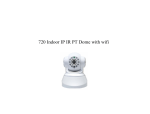
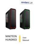
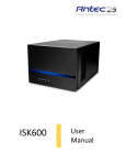
Video Source Management System
Installation & User’s Manual
MODEL 260
Video Valet® 260 Installation and User's Manual
Revision: H
Page: 1 of 16
Trademarks
Coretronics is a registered trademark, and
Video Valet is a trademark of Coretronics,
Inc.
Coretronics, Inc.
1251 E. Iron Eagle Drive
Eagle, ID 83616
Telephone: (208) 938-6331
Fax: (208) 938-6334
www.triptek.net
Video Valet® 260 Installation and User's Manual
Revision: H
Page: 2 of 16
Table of Contents
Table of Contents ..........................................................................3
Introduction....................................................................................4
Definition of Terms ........................................................................4
Dash Monitor Modes ....................................................................................4
Operating Modes ..........................................................................................5
Video Inputs .................................................................................................5
Video Outputs...............................................................................................7
Power Input/Output ......................................................................................7
Config. Switches...........................................................................................7
Specifications ................................................................................7
Installation......................................................................................8
Wiring the Video Valet 260 Power Harness .................................................8
Rocker Switches...........................................................................................9
Video Inputs ...............................................................................................10
Config. Switch Setup ..................................................................................10
Operation......................................................................................13
Rocker Switches.........................................................................................13
Driving Mode ..............................................................................................13
Security Mode ............................................................................................15
Video Valet® 260 Installation and User's Manual
Revision: H
Page: 3 of 16
Introduction
The Video Valet® 260 (VV260) is a video source management system
designed for motor vehicles. The Video Valet 260 will route up to 8 video
sources (one at a time) through two independent outputs (Dash 1 and
Bedroom/co-driver) in various orders depending upon how the Video Valet
is configured. Each of these outputs can be configured to display a different
grouping of inputs while the coach is in driving mode (i.e., the ignition is
turned on) or in security mode. The desired video sources are selected
from the chosen grouping via rocker switches installed in the dash and
bedroom.
A third output (Dash 2), which is directly connected to the rear camera
source, is also provided so that a two-monitor dash can be set up with one
monitor as a dedicated rear vision display.
VV260 manages all power requirements for cameras and monitors.
Switched power to all cameras (8 or 12 volts) are managed as required
while ignition is on or specific cameras during security mode. Rocker switch
activation will also turn on or off Bedroom/co-driver monitors during driving
or security mode and dash monitor in security mode. VV260 powers
reverse signal to Dash 1 monitor to switch between Dash 1 monitor
functions and programmed VV260 video signals.
Warning! It is illegal in most states to connect anything but the following
type of video input devices to the Video Valet 260: vehicle
information displays, navigation or global positioning displays,
mapping displays, or visual displays (i.e., cameras) used to
enhance the driver's ability to see.
Definition of Terms
Dash Monitor Modes
Single:
Just one monitor in the dash connected to the Dash 1 output of
the VV260.
Dual:
Two monitors in the dash. One is a dedicated rear camera
monitor connected to Dash 2. The other is connected to the
Dash 1 output and is used to multiplex though the other video
sources.
Video Valet® 260 Installation and User's Manual
Revision: H
Page: 4 of 16
Operating Modes
Driving:
Operating mode the VV260 is in when ignition/accessory is
turned on.
Sleep:
The VV260 enters Sleep mode when either the ignition is turned
off or in Security Mode if neither rocker switch has been used for
approximately five minutes. In Sleep Mode the VV260
consumes less than 15mA of electricity.
Video Valet
DASH 2
Video Inputs 1 - 4
POWER INPUT/OUTPUT
BEDROOM
Video Outputs
Figure 1
CONFIG. SWITCHES
Video Inputs 5 - 8
DA4SH 1
RCA CONNECTORS
Security: This mode of operation is entered by pushing and holding the
rocker switch (on either the dash or in the bedroom) while the
VV260 is in sleep mode (ignition off).
Video Valet Inputs and Outputs
Video Inputs
#1 Rear:
Video signal from the rear vision camera (required) 1.
#2 Left:
Video signal from the left (rear viewing) camera (required) 1.
#3 Right: Video signal from the right (rear viewing) camera (required) 1.
#4 Front: Video signal from camera looking out front windshield (optional) 2.
Video 5-8 2Optional video inputs. Can be used to tie in navigation systems,
additional cameras from inside and outside of the coach, etc.
1
2
The Video Valet is programmed such that it expects these inputs in order to operate correctly.
If an optional input is not present the Video Valet will skip over and not display it in its normal
operation. A video source is detected when (sense) pins of the video input connector are
grounded.
Video Valet® 260 Installation and User's Manual
Revision: H
Page: 5 of 16
The VV260 uses a 20 and 22 pin Molex connector to receive video input
from the various video sources and to provide power for cameras. Pinouts
of interconnect cables for customers that want to build their own cable
solutions are as follows:
20 pin Connector
MOLEX 39-01-2200
PIN#
FUNCTION
1
VIDEO 4 12VDC
2
VIDEO 4 SENSE
3
VIDEO 4 8.1 VDC
4
VIDEO 3 GROUND
5
VIDEO 3 8.1 VDC
6
VIDEO 2 GROUND
7
VIDEO 2 8.1 VDC
8
VIDEO 1 GROUND
9
VIDEO 1 8.1 VDC
10
VIDEO 1 SENSE
11
VIDEO 4 VIDEO IN
12
VIDEO 4 GROUND
13
VIDEO 3 12 VDC
14
VIDEO 3 VIDEO IN
15
VIDEO 3 SENSE
16
VIDEO 2 12 VDC
17
VIDEO 2 VIDEO IN
18
VIDEO 2 SENSE
19
VIDEO 1 VIDEO IN
20
VIDEO 1 12 VDC
22 pin Connector
MOLEX 39-01-2220
PIN#
FUNCTION
1
VIDEO 5 12VDC
2
VIDEO 5 GROUND
3
VIDEO 5 8.1 VDC
4
VIDEO 6 GROUND
5
VIDEO 6 8.1 VDC
6
NC
7
VIDEO 7 GROUND
8
VIDEO 7 8.1 VDC
9
VIDEO 8 GROUND
10
VIDEO 8 8.1 VDC
11
VIDEO 8 SENSE
12
VIDEO 5 VIDEO IN
13
VIDEO 5 SENSE
14
VIDEO 6 12 VDC
15
VIDEO 6 VIDEO IN
16
VIDEO 6 SENSE
17
NC
18
VIDEO 7 12 VDC
19
VIDEO 7 VIDEO IN
20
VIDEO 7 SENSE
21
VIDEO 8 12 VDC
22
VIDEO 8 VIDEO IN
Video harnesses offered by Coretronics with the above referenced
connectors has a dedicated female phono jack and Molex 4 pin connector
for each video input.
4 pin Connector
Molex 39-01-3043
PIN#
FUNCTION
1
SENSE
2
GROUND
3
8.1 VDC
4
12 VDC
Video Valet® 260 Installation and User's Manual
Revision: H
Page: 6 of 16
Video Outputs
Dash 1
Configurable output for dash.
Dash 2
Displays the rear camera input only.
Bedroom Configurable output for bedroom/co-driver television or monitor.
Power Input/Output
The Power Input/Output connector provides power to the VV260 as well as
inputs (such as left and right turn signals) and outputs (power to the
bedroom monitor, etc). A wiring harness is provided with the VV260. A
pinout of the Power Input/Output connector is provided in Table 1 of the
Installation section of this manual.
Warning! Power output for monitor is designed to activate a relay to power
the monitor. Output capacity is 1 Amp max.
Config. Switches
A set of eight dip switches is used in configuring the Video Valet's display
modes. For a more detailed description of switch function see the
Installation section.
Specifications
Power Requirements:
11 to 16 Vdc
Driving/Security Modes
0.6 to 1.1 Amps Typ. (Depends on the number and types of cameras)
Sleep Mode
Less than 15 mA
Control Outputs:
Monitors
11 to 16 Vdc (12 to 14 Vdc Typ.), 1 Amps max.
Video Valet® 260 Installation and User's Manual
Revision: H
Page: 7 of 16
Video Outputs:
1 Vpp into 75 ohms (Can be adjusted to drive two 75 ohm inputs using an
internal adjustment. Call for more information.)
Camera Power:
+12 Volts (Pin 4)
11 to 13 Vdc Typ., 250 mA max.
+8 Volts (Pin 2)
7.5 to 8.5 Vdc Typ., 250 mA max.
Control Inputs:
10 to 15 Vdc
Video Inputs:
1 Vpp CVBS, 75 ohm
Installation
Wiring the Video Valet 260 Power Harness
Using Table 1, wire the Video Valet 260's power harness into the coach.
Table 1
Pin
Color
Description
1
Red
Vehicle/House Battery
2
Red/White
Vehicle/House Battery
3
Green/Yellow
Dash 1 Monitor Ignition Power Out
4
White
Dash 1 Monitor Reverse Power Out
5
Black
Ground1
6
Blue
Left Turn Signal Input
7
Orange
Ignition/Accessory Switch
Video Valet® 260 Installation and User's Manual
Revision: H
Page: 8 of 16
Table 1
2
8
Grey/Black
Bedroom Rocker Switch "Up" Side
9
Red/Black
Bedroom/Co-Driver Monitor Power Out
10
Violet
Dash Rocker Switch "Down" Side
11
Green
Reverse Input
12
Black
Ground
13
2
1
N/C
14
Blue/White
15
Grey
16
Violet/White
Right Turn Signal Input
Bedroom Rocker Switch "Down" Side2
Dash Rocker Switch "Up" Side2
1 Pins 5 and 12 should be connected to the same location if
possible.
2 Figure 2 Shows the wiring of the rocker switches.
Down
Up
Battery
(Either Coach or House)
Figure 2
Rocker Switch
Rocker Switches
Wire rocker switches as shown in Figure 2. Switches can be either single
pole double throw (SPDT) or double pole double throw (DPDT) momentary
on switches.
Video Valet® 260 Installation and User's Manual
Revision: H
Page: 9 of 16
Video Inputs
Due to the wide variety of video sources and cable configurations, each
supported configuration will require customized cables. It is recommended
that Video Valet be turned off before connecting or disconnecting video
inputs cables.
Note: In order for the Video Valet to auto detect that the cable has been
connected to Video 4 (Front) or Video 5-8 inputs, (sense) pins of the video
input connectors must be connected to the appropriate ground. For more
information see Video Inputs in the Definition of Terms section of this
manual.
Config. Switch Setup
Since the Video Valet 260 is configurable, it must first be determined how it
will be operated. The minimum configuration would be just rear, left and
right cameras connected to the VV260 since these three cameras are the
minimum required for driving mode functionality and some security mode
functionality as well. A more complex set up would consist of four to six
outside cameras (rear, left, right, front, etc.) and up to four more auxiliary
video inputs, which can be anything that provides a NTSC composite video
output (interior cameras, navigation systems, etc.). For a more detailed
description of the video inputs see Video Inputs in the Definitions Of Terms
section of this document.
The following tables list the different modes the VV260 can be set up for as
well as the video source groupings that are selectable in each mode.
Table 2
Config. Switch
Dash Monitor Mode
1
OFF
Single
ON
Dual
Video Valet® 260 Installation and User's Manual
Revision: H
Page: 10 of 16
Table 3
Switches
2
3
4
Dash 1 Output: Driving Mode Video Input
Selection Order
OFF OFF OFF ?Receiver, *Rear, †Video 5, Video 6, Video 7, Video 8, Left, Right
ON
OFF OFF ?Receiver, *Rear, †Video 6, Video 7, Video 8, Left, Right
OFF ON
OFF ?Receiver, *Rear, †Video 7, Video 8, Left, Right
ON
OFF ?Receiver, *Rear, †Video 8, Left, Right
ON
OFF OFF ON
?Receiver, *Rear, †Video 5, Video 6, Video 7, Video 8
ON
?Receiver, *Rear, †Video 6, Video 7, Video 8
OFF ON
OFF ON
ON
?Receiver, *Rear, †Video 7, Video 8
ON
ON
?Receiver, *Rear, †Video 8
ON
? The receiver is the default when VV260 is powered on. The reverse signal
input to the monitor is not activated giving monitor display to monitor system
options.
* Rear camera is present only in Single Dash Monitor Mode. When the dash
rocker is activated, in Single Dash Monitor Mode, the default video source will
be the Rear camera. The activation of the rocker switch will also activate the
reverse signal input to the monitor.
† In Dual Monitor Mode the default video source will be the first valid video
source detected when the dash rocker is activated. The activation of the
rocker switch will also activate the reverse signal input to the monitor. For
example, in dual monitor mode, if Video 6 is the first auxiliary video input with a
video source connected to it then Video 6 will be the default video source.
Video Valet® 260 Installation and User's Manual
Revision: H
Page: 11 of 16
Table 4
Switch
Reverse Signal Activation
5
Dash 1 Monitor
OFF
12 Volt Signal Off for Left & Right Turn Signal
ON
12 Volt Signal On for Left & Right Turn Signal
Table 5
Switch
Reverse Signal Activation
6
Dash 1 Monitor
OFF
12 Volt Signal Off for Dash Rocker Activation
ON
12 Volt Signal On for Dash Rocker Activation
Table 6
Switches
7
8
Dash 1 & Bedroom Output: Security
Mode Video Input Selection Order
OFF OFF
Right, Rear, Left, †Front
ON
Right, Rear, Left, †Front, Video 5
OFF
OFF ON
Right, Rear, Left, †Front, Video 5, Video 6
ON
Rear, †Front, Video 5, Video 6
ON
† Front, Video 5, and Video 6 are only displayed if a valid input is
connected. If no camera is connected to the Front, Video 5 or 6 input
then the next camera will be displayed after the Left camera when going
“down” the list (i.e., it wraps around).
Video Valet® 260 Installation and User's Manual
Revision: H
Page: 12 of 16
Operation
Rocker Switches
Rocker switches can be installed near any monitor or television that is
connected to the VV260. These rocker switches are used to select a video
source to be displayed on that monitor/television from a selected list of
video sources shown in Tables 3, and 6. Which list is used depends on the
current mode of operation (i.e., Driving or Security), the dip switch settings
(see Tables 3, or 6 for the dip switch configurations), and which output on
the VV260 (Dash 1 or Bedroom/co-driver) the monitor/television is
connected to. There may be multiple rocker switches associated with the
either the Dash 1 or the Bedroom /co-driver outputs depending on how
many monitors are connected to each.
The rocker switches are two way momentary on switches, which means that
when you push either side of the switch and release it, the switch will move
back to the neutral position. Pressing one side of the switch will move you
“down” through the list mentioned above and the other side will move you
“up” through it. Upon reaching either end of the list the VV260 will wrap
around to the other end of the list with the next press.
Driving Mode
The VV260 is in Driving Mode when the ignition/accessory switch is on.
Details of the functionality provided in this mode are given below.
Dash 1 Output (Single Monitor Mode)
If using only one monitor in the dash, the dash rocker switch can be used to
select any video input from the selected list in Table 3 as described in the
Rocker Switches section above.
If the vehicle is put into reverse the normal rocker switch functionality is
suspended and the Rear camera input is displayed on the Dash 1 output.
When the vehicle is taken out of reverse then the previously chosen video
source will return to the monitor.
If either the left or right turn signal is activated (in normal Driving Mode or
when the coach is in reverse) normal rocker switch functionality is again
suspended and the Left or Right camera (respectively) will be routed to the
Video Valet® 260 Installation and User's Manual
Revision: H
Page: 13 of 16
Dash 1 output. After turning off the turn signal the Left or Right camera feed
(depending on which signal was on) will remain for about one second and
then return to the previously chosen video source.
Dash 1 Output (Dual Monitor Mode)
In Dual Monitor Mode the dash rocker switch can be used to select any
video input from the selected list in Table 3, with the exception of the Rear
camera input (which is displayed on the second dash monitor via the Dash 2
output), as described in the Rocker Switches section above.
If the vehicle is put into reverse the normal rocker switch functionality is
suspended and the Right camera input is routed to the Dash 1 output. This
can be changed to the Left camera by using the rocker switch to move back
and forth between these two cameras. When the vehicle is taken out of
reverse then the previously chosen video source will return to the monitor.
If either the left or right turn signal is activated, while not in reverse, then
normal rocker switch functionality is again suspended and the Left or Right
camera (respectively) will be routed to the Dash 1 output. After turning off
the turn signal the Left or Right camera feed (depending on which signal
was on) will remain for about five seconds and then return to the previously
chosen video source.
Bedroom/Co-Driver Output
If the VV260 is set up to control the power to your bedroom/co-driver
monitor, press the rocker switch to turn monitor on. If the VV260 is not set
up to control monitor power or is connected to a television, the monitor (or
television) will have to be turned on separately. The monitor (if powered by
the VV260) can be turned off by pressing the "down" side of the rocker
switch for about three seconds.
The Bedroom/co-driver rocker switch can be used to select all video inputs
that are utilized on Video Valet.
The Dash 1 and Bedroom outputs are independent of each other so that
different sources (from the same list) can be displayed on each at the same
time.
Video Valet® 260 Installation and User's Manual
Revision: H
Page: 14 of 16
Security Mode
Dash 1 and Bedroom Outputs in Security Mode
To enter Security Mode press and hold the “up” or “down” side of the dash
or bedroom/co-driver rocker switch while the VV260 is in Sleep Mode (i.e.,
the ignition is turned off). If the rocker switch is not pressed again the Video
Valet will start scanning through the video inputs from the selected list in
Table 6 (i.e., it will start on the first input of the list and after two seconds
display the next input and so on, down through the list, starting over at the
beginning when the end is reached). To stop the scanning, press either side
of a rocker switch that corresponds to the output being displayed. After
scanning is stopped the rocker switch can be used to move up and down
through the selected list of video inputs (see Rocker Switches section for
more details). The VV260 will return to Sleep Mode after about five minute
if there have been no inputs from any of the rocker switches. The timeout
countdown starts over every time a rocker switch in pressed.
If the VV260 is set up to control the power to the monitor (either the dash
monitor(s) or the bedroom), the monitor(s) under control can be turned off
by pressing the "down" side of the rocker switch for about three seconds or
they will time off after 5 minutes. This does not put the VV260 into Sleep
Mode; it just shuts off the monitor; someone can still use the VV260 from
another monitor/television whose power is not controlled by the video valet.
To turn the monitor back on press and hold the rocker switch.
The Dash 1 and Bedroom/co-driver outputs are independent of each other so
that different sources (from the same list) can be displayed on each at the
same time.
Video Valet® 260 Installation and User's Manual
Revision: H
Page: 15 of 16
Video Valet Product Warranty
Coretronics, Inc. (the Company) warrants Video Valet to be free of defects in
material and workmanship under normal use and service maintenance for a period
of 12 months. In the event Video Valet proves to be defective in material or
workmanship during said 12-month warranty period, Coretronics, Inc. will, at its
option, repair or replace the unit, at no charge to Customer except as set forth
below. All replaced parts and equipment shall become the property of Coretronics.
This limited warranty does not apply to any damage to Video Valet resulting from
accident, physical or electrical misuse or abuse, improper installation, alteration,
any use contrary to its intended function, unauthorized service (i.e. service by
anyone other than the Company or its authorized service personnel), fire, flood,
lighting, or other acts of God.
This warranty limits the Company’s liability to the repair or replacement of the
product. The Company shall not be responsible for removal and/or reinstallation
charges, loss or damage in transit and shipping and mailing costs to the warranty
service location.
The Company reserves the right to make changes or improvements in its products
without incurring any obligation to similarly alter products previously purchased.
Video Valet® 260 Installation and User's Manual
Revision: H
Page: 16 of 16