1
WinDriver™ PCI/ISA/CardBus User’s Manual
Version 10.02
http://www.jungo.com
COPYRIGHT
© Jungo Ltd. 2005 – 2009 All Rights Reserved.
Information in this document is subject to change without notice. The software
described in this document is furnished under a license agreement. The software
may be used, copied or distributed only in accordance with that agreement. No part
of this publication may be reproduced, stored in a retrieval system, or transmitted in
any form or any means, electronically or mechanically, including photocopying and
recording for any purpose without the written permission of Jungo Ltd.
Brand and product names mentioned in this document are trademarks of their
respective holders and are used here only for identification purposes.
1
Contents
Table of Contents
2
List of Figures
1
2
13
WinDriver Overview
1.1
Introduction to WinDriver . . . . . . . . . . . . . .
1.2
Background . . . . . . . . . . . . . . . . . . . . . .
1.2.1 The Challenge . . . . . . . . . . . . . . . .
1.2.2 The WinDriver Solution . . . . . . . . . . .
1.3
How Fast Can WinDriver Go? . . . . . . . . . . . .
1.4
Conclusion . . . . . . . . . . . . . . . . . . . . . .
1.5
WinDriver Benefits . . . . . . . . . . . . . . . . . .
1.6
WinDriver Architecture . . . . . . . . . . . . . . . .
1.7
What Platforms Does WinDriver Support? . . . . . .
1.8
Limitations of the Different Evaluation Versions . . .
1.9
How Do I Develop My Driver with WinDriver? . . .
1.9.1 On Windows and Linux . . . . . . . . . . .
1.9.2 On Windows CE . . . . . . . . . . . . . . .
1.10 What Does the WinDriver Toolkit Include? . . . . .
1.10.1 WinDriver Modules . . . . . . . . . . . . .
1.10.2 Utilities . . . . . . . . . . . . . . . . . . . .
1.10.3 WinDriver’s Specific Chipset Support . . . .
1.10.4 Samples . . . . . . . . . . . . . . . . . . .
1.11 Can I Distribute the Driver Created with WinDriver?
.
.
.
.
.
.
.
.
.
.
.
.
.
.
.
.
.
.
.
.
.
.
.
.
.
.
.
.
.
.
.
.
.
.
.
.
.
.
.
.
.
.
.
.
.
.
.
.
.
.
.
.
.
.
.
.
.
.
.
.
.
.
.
.
.
.
.
.
.
.
.
.
.
.
.
.
.
.
.
.
.
.
.
.
.
.
.
.
.
.
.
.
.
.
.
.
.
.
.
.
.
.
.
.
.
.
.
.
.
.
.
.
.
.
.
.
.
.
.
.
.
.
.
.
.
.
.
.
.
.
.
.
.
.
.
.
.
.
.
.
.
.
.
.
.
.
.
.
.
.
.
.
14
14
15
15
16
17
17
18
19
20
21
21
21
22
22
23
24
24
24
25
Understanding Device Drivers
2.1
Device Driver Overview . . . . . . . . . . . . . .
2.2
Classification of Drivers According to Functionality
2.2.1 Monolithic Drivers . . . . . . . . . . . . .
2.2.2 Layered Drivers . . . . . . . . . . . . . .
2.2.3 Miniport Drivers . . . . . . . . . . . . . .
.
.
.
.
.
.
.
.
.
.
.
.
.
.
.
.
.
.
.
.
.
.
.
.
.
.
.
.
.
.
.
.
.
.
.
.
.
.
.
.
26
26
27
27
28
28
2
.
.
.
.
.
CONTENTS
2.3
2.4
2.5
2.6
3
4
Classification of Drivers According to Operating Systems
2.3.1 WDM Drivers . . . . . . . . . . . . . . . . . .
2.3.2 VxD Drivers . . . . . . . . . . . . . . . . . . .
2.3.3 Unix Device Drivers . . . . . . . . . . . . . . .
2.3.4 Linux Device Drivers . . . . . . . . . . . . . .
The Entry Point of the Driver . . . . . . . . . . . . . . .
Associating the Hardware to the Driver . . . . . . . . .
Communicating with Drivers . . . . . . . . . . . . . . .
3
.
.
.
.
.
.
.
.
.
.
.
.
.
.
.
.
.
.
.
.
.
.
.
.
.
.
.
.
.
.
.
.
.
.
.
.
.
.
.
.
.
.
.
.
.
.
.
.
29
29
30
30
30
31
31
31
.
.
.
.
.
.
.
.
.
.
.
.
.
.
33
33
33
34
34
35
35
36
Installing WinDriver
3.1
System Requirements . . . . . . . . . . . . . . . . . . . . . . .
3.1.1 Windows System Requirements . . . . . . . . . . . . .
3.1.2 Windows CE System Requirements . . . . . . . . . . .
3.1.3 Linux System Requirements . . . . . . . . . . . . . . .
3.2
WinDriver Installation Process . . . . . . . . . . . . . . . . . .
3.2.1 Windows WinDriver Installation Instructions . . . . . .
3.2.2 Windows CE WinDriver Installation Instructions . . . .
3.2.2.1 Installing WinDriver CE when Building New
CE-Based Platforms . . . . . . . . . . . . .
3.2.2.2 Installing WinDriver CE when Developing
Applications for Windows CE Computers . .
3.2.2.3 Windows CE Installation Note . . . . . . . .
3.2.3 Linux WinDriver Installation Instructions . . . . . . . .
3.2.3.1 Preparing the System for Installation . . . .
3.2.3.2 Installation . . . . . . . . . . . . . . . . . .
3.2.3.3 Restricting Hardware Access on Linux . . .
3.3
Upgrading Your Installation . . . . . . . . . . . . . . . . . . .
3.4
Checking Your Installation . . . . . . . . . . . . . . . . . . . .
3.4.1 Windows and Linux Installation Check . . . . . . . . .
3.4.2 Windows CE Installation Check . . . . . . . . . . . . .
3.5
Uninstalling WinDriver . . . . . . . . . . . . . . . . . . . . . .
3.5.1 Windows WinDriver Uninstall Instructions . . . . . . .
3.5.2 Linux WinDriver Uninstall Instructions . . . . . . . . .
. .
36
.
.
.
.
.
.
.
.
.
.
.
.
.
.
.
.
.
.
.
.
.
.
.
.
.
.
38
39
40
40
41
43
43
44
44
44
45
45
47
Using DriverWizard
4.1
An Overview . . . . . . . . . . . . . . . . . . . . . . . . . . .
4.2
DriverWizard Walkthrough . . . . . . . . . . . . . . . . . . . .
4.2.1 Logging WinDriver API Calls . . . . . . . . . . . . . .
4.2.2 DriverWizard Logger . . . . . . . . . . . . . . . . . .
4.2.3 Automatic Code Generation . . . . . . . . . . . . . . .
4.2.3.1 Generating the Code . . . . . . . . . . . . .
4.2.3.2 The Generated PCI/PCMCIA/ISA C Code .
4.2.3.3 The Generated Visual Basic and Delphi Code
.
.
.
.
.
.
.
.
.
.
.
.
.
.
.
.
48
48
49
58
59
59
59
59
60
CONTENTS
4
.
.
.
.
.
.
.
.
.
.
.
.
.
.
.
.
60
60
60
61
.
.
.
.
.
.
.
.
.
.
.
.
.
.
.
.
.
.
.
.
.
.
.
.
.
.
.
.
.
.
.
.
.
.
.
.
.
.
.
.
62
62
63
63
64
65
66
66
66
66
66
Debugging Drivers
6.1
User-Mode Debugging . . . . . . . . . . . . . . . . . . . . . .
6.2
Debug Monitor . . . . . . . . . . . . . . . . . . . . . . . . . .
6.2.1 The wddebug_gui Utility . . . . . . . . . . . . . . . .
6.2.1.1 Running wddebug_gui for a Renamed Driver
6.2.2 The wddebug Utility . . . . . . . . . . . . . . . . . . .
6.2.2.1 Console-Mode wddebug Execution . . . . .
6.2.2.2 Windows CE GUI wddebug Execution . . .
.
.
.
.
.
.
.
.
.
.
.
.
.
.
67
67
68
68
70
71
71
75
7
Enhanced Support for Specific Chipsets
7.1
Overview . . . . . . . . . . . . . . . . . . . . . . . . . . . . . . .
7.2
Developing a Driver Using the Enhanced Chipset Support . . . . .
76
76
77
8
PCI Express
8.1
PCI Express Overview . . . . . . . . . . . . . . . . . . . . . . . .
8.2
WinDriver for PCI Express . . . . . . . . . . . . . . . . . . . . . .
78
78
80
9
Advanced Issues
9.1
Performing Direct Memory Access (DMA) . . . . . . . . . . .
9.1.1 Scatter/Gather DMA . . . . . . . . . . . . . . . . . . .
9.1.1.1 Sample Scatter/Gather DMA Implementation
9.1.1.2 What Should You Implement? . . . . . . . .
9.1.2 Contiguous Buffer DMA . . . . . . . . . . . . . . . . .
9.1.2.1 Sample Contiguous Buffer DMA
Implementation . . . . . . . . . . . . . . . .
9.1.2.2 What Should You Implement? . . . . . . . .
.
.
.
.
.
81
81
82
83
85
85
. .
. .
86
88
4.2.4
5
6
4.2.3.4 The Generated C# Code . . . . . . . . .
Compiling the Generated Code . . . . . . . . . . .
4.2.4.1 Windows and Windows CE Compilation:
4.2.4.2 Linux Compilation . . . . . . . . . . . .
Developing a Driver
5.1
Using the DriverWizard to Build a Device Driver . .
5.2
Writing the Device Driver Without the DriverWizard
5.2.1 Include the Required WinDriver Files . . . .
5.2.2 Write Your Code . . . . . . . . . . . . . . .
5.3
Developing Your Driver on Windows CE Platforms .
5.4
Developing in Visual Basic and Delphi . . . . . . . .
5.4.1 Using DriverWizard . . . . . . . . . . . . .
5.4.2 Samples . . . . . . . . . . . . . . . . . . .
5.4.3 Kernel PlugIn . . . . . . . . . . . . . . . .
5.4.4 Creating your Driver . . . . . . . . . . . . .
.
.
.
.
.
.
.
.
.
.
.
.
.
.
.
.
.
.
.
.
.
.
.
.
.
.
.
.
.
.
.
.
.
.
.
.
.
.
.
.
.
.
.
.
.
CONTENTS
9.2
9.3
5
9.1.3 Performing DMA on SPARC . . . . . . . . . . . . . . . .
Handling Interrupts . . . . . . . . . . . . . . . . . . . . . . . . . .
9.2.1 Interrupt Handling – Overview . . . . . . . . . . . . . . .
9.2.2 WinDriver Interrupt Handling Sequence . . . . . . . . . .
9.2.3 Determining the Interrupt Types Supported by the Hardware
9.2.4 Determining the Interrupt Type Enabled for a PCI Card . .
9.2.5 Setting Up Kernel-Mode Interrupt Transfer Commands . .
9.2.5.1 Interrupt Mask Commands . . . . . . . . . . . .
9.2.5.2 Sample WinDriver Transfer Commands Code . .
9.2.6 WinDriver MSI/MSI-X Interrupt Handling . . . . . . . . .
9.2.6.1 Windows MSI/MSI-X Device INF Files . . . . .
9.2.7 Sample User-Mode WinDriver Interrupt Handling Code . .
9.2.8 Interrupts on Windows CE . . . . . . . . . . . . . . . . . .
9.2.8.1 Improving Interrupt Latency on Windows CE . .
Byte Ordering . . . . . . . . . . . . . . . . . . . . . . . . . . . . .
9.3.1 Introduction to Endianness . . . . . . . . . . . . . . . . . .
9.3.2 WinDriver Byte Ordering Macros . . . . . . . . . . . . . .
9.3.3 Macros for PCI Target Access . . . . . . . . . . . . . . . .
9.3.4 Macros for PCI Master Access . . . . . . . . . . . . . . .
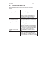
10 Improving Performance
10.1 Overview . . . . . . . . . . . . . . . . . . . . . . . . . .
10.1.1 Performance Improvement Checklist . . . . . . .
10.2 Improving the Performance of a User-Mode Driver . . . .
10.2.1 Using Direct Access to Memory-Mapped Regions
10.2.2 Block Transfers and Grouping Multiple Transfers
10.2.3 Performing 64-bit Data Transfers . . . . . . . . .
.
.
.
.
.
.
.
.
.
.
.
.
.
.
.
.
.
.
.
.
.
.
.
.
.
.
.
.
.
.
11 Understanding the Kernel PlugIn
11.1 Background . . . . . . . . . . . . . . . . . . . . . . . . . . . . . .
11.2 Do I Need to Write a Kernel PlugIn Driver? . . . . . . . . . . . . .
11.3 What Kind of Performance Can I Expect? . . . . . . . . . . . . . .
11.4 Overview of the Development Process . . . . . . . . . . . . . . . .
11.5 The Kernel PlugIn Architecture . . . . . . . . . . . . . . . . . . .
11.5.1 Architecture Overview . . . . . . . . . . . . . . . . . . . .
11.5.2 WinDriver’s Kernel and Kernel PlugIn Interaction . . . . .
11.5.3 Kernel PlugIn Components . . . . . . . . . . . . . . . . .
11.5.4 Kernel PlugIn Event Sequence . . . . . . . . . . . . . . . .
11.5.4.1 Opening Handle from the User Mode to a Kernel
PlugIn Driver . . . . . . . . . . . . . . . . . . .
11.5.4.2 Handling User-Mode Requests from the Kernel
PlugIn . . . . . . . . . . . . . . . . . . . . . .
88
89
89
91
92
93
93
94
95
96
97
98
100
101
103
103
103
104
105
106
106
107
108
108
109
109
111
111
112
112
112
113
113
114
114
115
115
116
CONTENTS
11.6
6
11.5.4.3 Interrupt Handling – Enable/Disable and High
Interrupt Request Level Processing . . . . . . .
11.5.4.4 Interrupt Handling – Deferred Procedure Calls .
11.5.4.5 Plug-and-Play and Power Management Events .
How Does Kernel PlugIn Work? . . . . . . . . . . . . . . . . . . .
11.6.1 Minimal Requirements for Creating a Kernel PlugIn Driver
11.6.2 Kernel PlugIn Implementation . . . . . . . . . . . . . . . .
11.6.2.1 Before You Begin . . . . . . . . . . . . . . . .
11.6.2.2 Write Your KP_Init() Function . . . . . . . . . .
11.6.2.3 Write Your KP_Open() Function . . . . . . . . .
11.6.2.4 Write the Remaining PlugIn Callbacks . . . . .
11.6.3 Sample/Generated Kernel PlugIn Driver Code Overview . .
11.6.4 Kernel PlugIn Sample/Generated Code Directory Structure
11.6.4.1 pci_diag and kp_pci Sample Directories . . . . .
11.6.4.2 The Generated DriverWizard Kernel PlugIn
Directory . . . . . . . . . . . . . . . . . . . . .
11.6.5 Handling Interrupts in the Kernel PlugIn . . . . . . . . . .
11.6.5.1 Interrupt Handling in the User Mode (Without
Kernel PlugIn) . . . . . . . . . . . . . . . . . .
11.6.5.2 Interrupt Handling in the Kernel (Using a Kernel
PlugIn) . . . . . . . . . . . . . . . . . . . . . .
11.6.6 Message Passing . . . . . . . . . . . . . . . . . . . . . . .
12 Writing a Kernel PlugIn
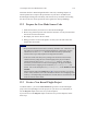
12.1 Determine Whether a Kernel PlugIn is Needed
12.2 Prepare the User-Mode Source Code . . . . .
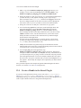
12.3 Create a New Kernel PlugIn Project . . . . .
12.4 Create a Handle to the Kernel PlugIn . . . . .
12.5 Set Interrupt Handling in the Kernel PlugIn .
12.6 Set I/O Handling in the Kernel PlugIn . . . .
12.7 Compile Your Kernel PlugIn Driver . . . . .
12.7.1 On Windows . . . . . . . . . . . . .
12.7.2 On Linux . . . . . . . . . . . . . . .
12.8 Install Your Kernel PlugIn Driver . . . . . .
12.8.1 On Windows . . . . . . . . . . . . .
12.8.2 On Linux . . . . . . . . . . . . . . .
.
.
.
.
.
.
.
.
.
.
.
.
.
.
.
.
.
.
.
.
.
.
.
.
.
.
.
.
.
.
.
.
.
.
.
13 Dynamically Loading Your Driver
13.1 Why Do You Need a Dynamically Loadable Driver?
13.2 Windows Dynamic Driver Loading . . . . . . . . .
13.2.1 Windows Driver Types . . . . . . . . . . .
13.2.2 The WDREG Utility . . . . . . . . . . . .
13.2.2.1 WDM Drivers . . . . . . . . .
116
117
118
119
119
120
120
120
122
127
127
129
129
131
132
133
134
136
.
.
.
.
.
.
.
.
.
.
.
.
.
.
.
.
.
.
.
.
.
.
.
.
.
.
.
.
.
.
.
.
.
.
.
.
.
.
.
.
.
.
.
.
.
.
.
.
.
.
.
.
.
.
.
.
.
.
.
.
.
.
.
.
.
.
.
.
.
.
.
.
.
.
.
.
.
.
.
.
.
.
.
.
.
.
.
.
.
.
.
.
.
.
.
.
.
.
.
.
.
.
.
.
.
.
.
.
137
137
138
138
139
140
141
141
141
144
145
145
145
.
.
.
.
.
.
.
.
.
.
.
.
.
.
.
.
.
.
.
.
.
.
.
.
.
.
.
.
.
.
.
.
.
.
.
.
.
.
.
.
.
.
.
.
146
146
147
147
147
148
CONTENTS
13.3
13.4
7
13.2.2.2 Non-WDM Drivers . . . . . . . . . . . . . . . .
13.2.3 Dynamically Loading/Unloading windrvr6.sys INF Files . .
13.2.4 Dynamically Loading/Unloading Your Kernel PlugIn Driver
Linux Dynamic Driver Loading . . . . . . . . . . . . . . . . . . .
Windows Mobile Dynamic Driver Loading . . . . . . . . . . . . .
14 Distributing Your Driver
14.1 Getting a Valid License for WinDriver . . . . . . . . . . . . . . .
14.2 Windows Driver Distribution . . . . . . . . . . . . . . . . . . . .
14.2.1 Preparing the Distribution Package . . . . . . . . . . . .
14.2.2 Installing Your Driver on the Target Computer . . . . . .
14.2.3 Installing Your Kernel PlugIn on the Target Computer . .
14.3 Windows CE Driver Distribution . . . . . . . . . . . . . . . . . .
14.3.1 Distribution to New Windows CE Platforms . . . . . . .
14.3.2 Distribution to Windows CE Computers . . . . . . . . . .
14.4 Linux Driver Distribution . . . . . . . . . . . . . . . . . . . . . .
14.4.1 Kernel Modules . . . . . . . . . . . . . . . . . . . . . .
14.4.2 User-Mode Hardware Control Application/Shared Objects
14.4.3 Kernel PlugIn Modules . . . . . . . . . . . . . . . . . .
14.4.4 Installation Script . . . . . . . . . . . . . . . . . . . . .
.
.
.
.
.
.
.
.
.
.
.
.
.
15 Driver Installation – Advanced Issues
15.1 Windows INF Files . . . . . . . . . . . . . . . . . . . . . . . . . .
15.1.1 Why Should I Create an INF File? . . . . . . . . . . . . .
15.1.2 How Do I Install an INF File When No Driver Exists? . . .
15.1.3 How Do I Replace an Existing Driver Using the INF File? .
15.2 Renaming the WinDriver Kernel Driver . . . . . . . . . . . . . . .
15.2.1 Windows Driver Rename . . . . . . . . . . . . . . . . . .
15.2.2 Linux Driver Rename . . . . . . . . . . . . . . . . . . . .
15.3 Digital Driver Signing & Certification – Windows Vista/Server
2008/Server 2003/XP/2000 . . . . . . . . . . . . . . . . . . . . . .
15.3.1 Overview . . . . . . . . . . . . . . . . . . . . . . . . . . .
15.3.1.1 Authenticode Driver Signature . . . . . . . . . .
15.3.1.2 WHQL Driver Certification . . . . . . . . . . .
15.3.2 Driver Signing & Certification of WinDriver-Based Drivers
15.3.2.1 WHQL DTM Test Notes . . . . . . . . . . . . .
15.4 Windows XP Embedded WinDriver Component . . . . . . . . . . .
149
151
152
153
153
154
154
155
156
156
159
160
160
162
163
163
165
165
166
167
167
168
168
169
170
170
173
174
174
175
175
176
177
178
A 64-bit Operating Systems Support
180
A.1 Supported 64-bit Architectures . . . . . . . . . . . . . . . . . . . . 180
A.2 Support for 32-bit Applications on 64-bit Architectures . . . . . . . 181
A.3 64-bit and 32-bit Data Types . . . . . . . . . . . . . . . . . . . . . 182
CONTENTS
B API Reference
B.1 WD_DriverName() . . . . . . . . . . . . . . . . . . . . . . . .
B.2 WDC Library Overview . . . . . . . . . . . . . . . . . . . . .
B.3 WDC High Level API . . . . . . . . . . . . . . . . . . . . . .
B.3.1 Structures, Types and General Definitions . . . . . . . .
B.3.1.1 WDC_DEVICE_HANDLE . . . . . . . . .
B.3.1.2 WDC_DRV_OPEN_OPTIONS Definitions .
B.3.1.3 WDC_DIRECTION Enumeration . . . . . .
B.3.1.4 WDC_ADDR_MODE Enumeration . . . . .
B.3.1.5 WDC_ADDR_RW_OPTIONS Enumeration
B.3.1.6 WDC_ADDR_SIZE Definitions . . . . . . .
B.3.1.7 WDC_SLEEP_OPTIONS Definitions . . . .
B.3.1.8 WDC_DBG_OPTIONS Definitions . . . . .
B.3.1.9 WDC_SLOT_U Union . . . . . . . . . . . .
B.3.1.10 WDC_PCI_SCAN_RESULT Structure . . .
B.3.1.11 WDC_PCMCIA_SCAN_RESULT Structure
B.3.2 WDC_DriverOpen() . . . . . . . . . . . . . . . . . . .
B.3.3 WDC_DriverClose() . . . . . . . . . . . . . . . . . . .
B.3.4 WDC_PciScanDevices() . . . . . . . . . . . . . . . . .
B.3.5 WDC_PciScanDevicesByTopology() . . . . . . . . . .
B.3.6 WDC_PcmciaScanDevices() . . . . . . . . . . . . . . .
B.3.7 WDC_PciGetDeviceInfo() . . . . . . . . . . . . . . . .
B.3.8 WDC_PcmciaGetDeviceInfo() . . . . . . . . . . . . . .
B.3.9 WDC_PciDeviceOpen() . . . . . . . . . . . . . . . . .
B.3.10 WDC_PcmciaDeviceOpen() . . . . . . . . . . . . . . .
B.3.11 WDC_IsaDeviceOpen() . . . . . . . . . . . . . . . . .
B.3.12 WDC_PciDeviceClose() . . . . . . . . . . . . . . . . .
B.3.13 WDC_PcmciaDeviceClose() . . . . . . . . . . . . . . .
B.3.14 WDC_IsaDeviceClose() . . . . . . . . . . . . . . . . .
B.3.15 WDC_CardCleanupSetup() . . . . . . . . . . . . . . .
B.3.16 WDC_KernelPlugInOpen() . . . . . . . . . . . . . . . .
B.3.17 WDC_CallKerPlug() . . . . . . . . . . . . . . . . . . .
B.3.18 WDC_ReadMemXXX() . . . . . . . . . . . . . . . . .
B.3.19 WDC_WriteMemXXX() . . . . . . . . . . . . . . . . .
B.3.20 WDC_ReadAddrXXX() . . . . . . . . . . . . . . . . .
B.3.21 WDC_WriteAddrXXX() . . . . . . . . . . . . . . . . .
B.3.22 WDC_ReadAddrBlock() . . . . . . . . . . . . . . . . .
B.3.23 WDC_WriteAddrBlock() . . . . . . . . . . . . . . . . .
B.3.24 WDC_MultiTransfer() . . . . . . . . . . . . . . . . . .
B.3.25 WDC_AddrSpaceIsActive() . . . . . . . . . . . . . . .
B.3.26 WDC_PciReadCfgBySlot() . . . . . . . . . . . . . . .
B.3.27 WDC_PciWriteCfgBySlot() . . . . . . . . . . . . . . .
8
.
.
.
.
.
.
.
.
.
.
.
.
.
.
.
.
.
.
.
.
.
.
.
.
.
.
.
.
.
.
.
.
.
.
.
.
.
.
.
.
.
.
.
.
.
.
.
.
.
.
.
.
.
.
.
.
.
.
.
.
.
.
.
.
.
.
.
.
.
.
.
.
.
.
.
.
.
.
.
.
.
.
183
184
186
187
187
187
187
188
189
189
190
190
190
193
193
194
195
196
197
198
200
201
202
204
207
210
213
214
215
216
218
220
222
223
224
226
228
230
232
233
234
236
CONTENTS
B.4
B.3.28 WDC_PciReadCfg() . . . . . . . . . . . . .
B.3.29 WDC_PciWriteCfg() . . . . . . . . . . . . .
B.3.30 WDC_PciReadCfgBySlotXXX() . . . . . . .
B.3.31 WDC_PciWriteCfgBySlotXXX() . . . . . .
B.3.32 WDC_PciReadCfgXXX() . . . . . . . . . .
B.3.33 WDC_PciWriteCfgXXX() . . . . . . . . . .
B.3.34 WDC_PcmciaReadAttribSpace() . . . . . . .
B.3.35 WDC_PcmciaWriteAttribSpace() . . . . . .
B.3.36 WDC_PcmciaSetWindow() . . . . . . . . .
B.3.37 WDC_PcmciaSetVpp() . . . . . . . . . . . .
B.3.38 WDC_DMAContigBufLock() . . . . . . . .
B.3.39 WDC_DMASGBufLock() . . . . . . . . . .
B.3.40 WDC_DMABufUnlock() . . . . . . . . . . .
B.3.41 WDC_DMASyncCpu() . . . . . . . . . . . .
B.3.42 WDC_DMASyncIo() . . . . . . . . . . . . .
B.3.43 WDC_SharedBufferAlloc() . . . . . . . . .
B.3.44 WDC_SharedBufferFree() . . . . . . . . . .
B.3.45 WDC_IntEnable() . . . . . . . . . . . . . .
B.3.46 WDC_IntDisable() . . . . . . . . . . . . . .
B.3.47 WDC_IntIsEnabled() . . . . . . . . . . . . .
B.3.48 WDC_EventRegister() . . . . . . . . . . . .
B.3.49 WDC_EventUnregister() . . . . . . . . . . .
B.3.50 WDC_EventIsRegistered() . . . . . . . . . .
B.3.51 WDC_SetDebugOptions() . . . . . . . . . .
B.3.52 WDC_Err() . . . . . . . . . . . . . . . . . .
B.3.53 WDC_Trace() . . . . . . . . . . . . . . . . .
B.3.54 WDC_GetWDHandle() . . . . . . . . . . . .
B.3.55 WDC_GetDevContext() . . . . . . . . . . .
B.3.56 WDC_GetBusType() . . . . . . . . . . . . .
B.3.57 WDC_Sleep() . . . . . . . . . . . . . . . . .
B.3.58 WDC_Version() . . . . . . . . . . . . . . .
WDC Low Level API . . . . . . . . . . . . . . . . .
B.4.1 WDC_ID_U Union . . . . . . . . . . . . .
B.4.2 WDC_ADDR_DESC Structure . . . . . . .
B.4.3 WDC_DEVICE Structure . . . . . . . . . .
B.4.4 PWDC_DEVICE . . . . . . . . . . . . . .
B.4.5 WDC_MEM_DIRECT_ADDR Macro . . .
B.4.6 WDC_ADDR_IS_MEM Macro . . . . . . .
B.4.7 WDC_GET_ADDR_DESC Macro . . . . .
B.4.8 WDC_GET_ENABLED_INT_TYPE Macro
B.4.9 WDC_GET_INT_OPTIONS Macro . . . . .
B.4.10 WDC_INT_IS_MSI Macro . . . . . . . . .
9
.
.
.
.
.
.
.
.
.
.
.
.
.
.
.
.
.
.
.
.
.
.
.
.
.
.
.
.
.
.
.
.
.
.
.
.
.
.
.
.
.
.
.
.
.
.
.
.
.
.
.
.
.
.
.
.
.
.
.
.
.
.
.
.
.
.
.
.
.
.
.
.
.
.
.
.
.
.
.
.
.
.
.
.
.
.
.
.
.
.
.
.
.
.
.
.
.
.
.
.
.
.
.
.
.
.
.
.
.
.
.
.
.
.
.
.
.
.
.
.
.
.
.
.
.
.
.
.
.
.
.
.
.
.
.
.
.
.
.
.
.
.
.
.
.
.
.
.
.
.
.
.
.
.
.
.
.
.
.
.
.
.
.
.
.
.
.
.
.
.
.
.
.
.
.
.
.
.
.
.
.
.
.
.
.
.
.
.
.
.
.
.
.
.
.
.
.
.
.
.
.
.
.
.
.
.
.
.
.
.
.
.
.
.
.
.
.
.
.
.
.
.
.
.
.
.
.
.
.
.
.
.
.
.
.
.
.
.
.
.
.
.
.
.
.
.
.
.
.
.
.
.
.
.
.
.
.
.
.
.
.
.
.
.
.
.
.
.
.
.
.
.
.
.
.
.
.
.
.
.
.
.
.
.
.
.
.
.
.
.
.
.
.
.
.
.
.
.
.
.
.
.
.
.
.
.
.
.
.
.
.
.
.
.
.
.
.
.
.
.
.
.
.
.
.
.
.
.
.
.
.
.
.
.
.
.
238
239
240
242
244
246
248
249
250
251
252
254
256
257
259
261
263
264
269
270
271
274
275
276
278
279
280
281
282
283
284
285
285
285
286
287
288
289
290
291
293
294
CONTENTS
B.5
B.6
B.4.11 WDC_GET_ENABLED_INT_LAST_MSG Macro
B.4.12 WDC_IS_KP Macro . . . . . . . . . . . . . . . .
WD_xxx Structures, Types and General Definitions . . . .
B.5.1 WD_BUS_TYP Enumeration . . . . . . . . . . .
B.5.2 ITEM_TYPE Enumeration . . . . . . . . . . . .
B.5.3 WD_PCMCIA_ACC_SPEED Enumeration . . . .
B.5.4 WD_PCMCIA_ACC_WIDTH Enumeration . . .
B.5.5 WD_PCMCIA_VPP Enumeration . . . . . . . . .
B.5.6 WD_PCI_ID Structure . . . . . . . . . . . . . . .
B.5.7 WD_PCMCIA_ID Structure . . . . . . . . . . . .
B.5.8 WD_PCI_SLOT Structure . . . . . . . . . . . . .
B.5.9 WD_PCMCIA_SLOT Structure . . . . . . . . . .
B.5.10 WD_ITEMS Structure . . . . . . . . . . . . . . .
B.5.11 WD_CARD Structure . . . . . . . . . . . . . . .
B.5.12 WD_PCI_CARD_INFO Structure . . . . . . . . .
B.5.13 WD_PCMCIA_CARD_INFO Structure . . . . . .
B.5.14 WD_DMA Structure . . . . . . . . . . . . . . . .
B.5.15 WD_TRANSFER Structure . . . . . . . . . . . .
Kernel PlugIn Kernel-Mode Functions . . . . . . . . . . .
B.6.1 KP_Init() . . . . . . . . . . . . . . . . . . . . . .
B.6.2 KP_Open() . . . . . . . . . . . . . . . . . . . . .
B.6.3 KP_Close() . . . . . . . . . . . . . . . . . . . . .
B.6.4 KP_Call() . . . . . . . . . . . . . . . . . . . . . .
B.6.5 KP_Event() . . . . . . . . . . . . . . . . . . . . .
B.6.6 KP_IntEnable() . . . . . . . . . . . . . . . . . . .
B.6.7 KP_IntDisable() . . . . . . . . . . . . . . . . . .
B.6.8 KP_IntAtIrql() . . . . . . . . . . . . . . . . . . .
B.6.9 KP_IntAtDpc() . . . . . . . . . . . . . . . . . . .
B.6.10 KP_IntAtIrqlMSI() . . . . . . . . . . . . . . . . .
B.6.11 KP_IntAtDpcMSI() . . . . . . . . . . . . . . . . .
B.6.12 COPY_TO_USER_OR_KERNEL,
COPY_FROM_USER_OR_KERNEL . . . . . .
B.6.13 Kernel PlugIn Synchronization APIs . . . . . . .
B.6.13.1 Kernel PlugIn Synchronization Types .
B.6.13.2 kp_spinlock_init() . . . . . . . . . . . .
B.6.13.3 kp_spinlock_wait() . . . . . . . . . . .
B.6.13.4 kp_spinlock_release() . . . . . . . . . .
B.6.13.5 kp_spinlock_uninit() . . . . . . . . . .
B.6.13.6 kp_interlocked_init() . . . . . . . . . .
B.6.13.7 kp_interlocked_uninit() . . . . . . . . .
B.6.13.8 kp_interlocked_increment() . . . . . .
B.6.13.9 kp_interlocked_decrement() . . . . . .
10
.
.
.
.
.
.
.
.
.
.
.
.
.
.
.
.
.
.
.
.
.
.
.
.
.
.
.
.
.
.
.
.
.
.
.
.
.
.
.
.
.
.
.
.
.
.
.
.
.
.
.
.
.
.
.
.
.
.
.
.
.
.
.
.
.
.
.
.
.
.
.
.
.
.
.
.
.
.
.
.
.
.
.
.
.
.
.
.
.
.
.
.
.
.
.
.
.
.
.
.
.
.
.
.
.
.
.
.
.
.
.
.
.
.
.
.
.
.
.
.
.
.
.
.
.
.
.
.
.
.
.
.
.
.
.
.
.
.
.
.
.
.
.
.
.
.
.
.
.
295
296
297
297
297
298
298
298
299
299
299
300
300
307
307
308
309
311
314
315
317
319
320
323
325
327
328
331
333
335
.
.
.
.
.
.
.
.
.
.
.
.
.
.
.
.
.
.
.
.
.
.
.
.
.
.
.
.
.
.
.
.
.
.
.
.
.
.
.
.
.
.
.
.
.
.
.
.
.
.
.
.
.
.
.
337
338
338
339
340
341
342
343
344
345
346
CONTENTS
B.7
B.8
B.9
B.6.13.10 kp_interlocked_add() . . .
B.6.13.11 kp_interlocked_read() . . .
B.6.13.12 kp_interlocked_set() . . .
B.6.13.13 kp_interlocked_exchange()
Kernel PlugIn Structure Reference . . . . . .
B.7.1 WD_KERNEL_PLUGIN . . . . . .
B.7.2 WD_INTERRUPT . . . . . . . . . .
B.7.3 WD_KERNEL_PLUGIN_CALL . .
B.7.4 KP_INIT . . . . . . . . . . . . . . .
B.7.5 KP_OPEN_CALL . . . . . . . . . .
User-Mode Utility Functions . . . . . . . . .
B.8.1 Stat2Str() . . . . . . . . . . . . . . .
B.8.2 get_os_type() . . . . . . . . . . . . .
B.8.3 ThreadStart() . . . . . . . . . . . . .
B.8.4 ThreadWait() . . . . . . . . . . . . .
B.8.5 OsEventCreate() . . . . . . . . . . .
B.8.6 OsEventClose() . . . . . . . . . . . .
B.8.7 OsEventWait() . . . . . . . . . . . .
B.8.8 OsEventSignal() . . . . . . . . . . .
B.8.9 OsEventReset() . . . . . . . . . . . .
B.8.10 OsMutexCreate() . . . . . . . . . . .
B.8.11 OsMutexClose() . . . . . . . . . . .
B.8.12 OsMutexLock() . . . . . . . . . . . .
B.8.13 OsMutexUnlock() . . . . . . . . . .
B.8.14 PrintDbgMessage() . . . . . . . . . .
B.8.15 WD_LogStart() . . . . . . . . . . . .
B.8.16 WD_LogStop() . . . . . . . . . . . .
B.8.17 WD_LogAdd() . . . . . . . . . . . .
WinDriver Status Codes . . . . . . . . . . .
B.9.1 Introduction . . . . . . . . . . . . .
B.9.2 Status Codes Returned by WinDriver
C Troubleshooting and Support
11
.
.
.
.
.
.
.
.
.
.
.
.
.
.
.
.
.
.
.
.
.
.
.
.
.
.
.
.
.
.
.
.
.
.
.
.
.
.
.
.
.
.
.
.
.
.
.
.
.
.
.
.
.
.
.
.
.
.
.
.
.
.
.
.
.
.
.
.
.
.
.
.
.
.
.
.
.
.
.
.
.
.
.
.
.
.
.
.
.
.
.
.
.
.
.
.
.
.
.
.
.
.
.
.
.
.
.
.
.
.
.
.
.
.
.
.
.
.
.
.
.
.
.
.
.
.
.
.
.
.
.
.
.
.
.
.
.
.
.
.
.
.
.
.
.
.
.
.
.
.
.
.
.
.
.
.
.
.
.
.
.
.
.
.
.
.
.
.
.
.
.
.
.
.
.
.
.
.
.
.
.
.
.
.
.
.
.
.
.
.
.
.
.
.
.
.
.
.
.
.
.
.
.
.
.
.
.
.
.
.
.
.
.
.
.
.
.
.
.
.
.
.
.
.
.
.
.
.
.
.
.
.
.
.
.
.
.
.
.
.
.
.
.
.
.
.
.
.
.
.
.
.
.
.
.
.
.
.
.
.
.
.
.
.
.
.
.
.
.
.
.
.
.
.
.
.
.
.
.
.
.
.
.
.
.
.
.
.
.
.
.
.
.
.
.
.
.
.
.
.
.
.
.
.
.
.
.
.
.
.
.
.
.
.
.
.
.
.
.
.
.
.
.
.
.
.
.
.
.
.
.
.
.
.
.
.
.
.
.
.
.
.
.
.
.
.
.
.
.
.
.
.
.
.
.
.
.
.
.
.
.
.
.
.
.
.
.
.
.
.
.
.
347
348
349
350
351
351
352
353
354
355
357
357
358
359
360
361
362
363
364
365
366
367
368
369
370
371
372
373
374
374
375
376
D Evaluation Version Limitations
377
D.1 Windows WinDriver Evaluation Limitations . . . . . . . . . . . . . 377
D.2 Windows CE WinDriver Evaluation Limitations . . . . . . . . . . . 378
D.3 Linux WinDriver Evaluation Limitations . . . . . . . . . . . . . . . 378
E Purchasing WinDriver
379
F Distributing Your Driver – Legal Issues
380
CONTENTS
G Additional Documentation
12
381
List of Figures
1.1
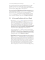
WinDriver Architecture . . . . . . . . . . . . . . . . . . . . . . . . .
19
2.1
2.2
2.3
Monolithic Drivers . . . . . . . . . . . . . . . . . . . . . . . . . . .
Layered Drivers . . . . . . . . . . . . . . . . . . . . . . . . . . . . .
Miniport Drivers . . . . . . . . . . . . . . . . . . . . . . . . . . . .
27
28
29
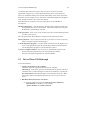
4.1
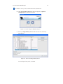
4.2
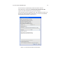
4.3
4.4
4.5
4.6
4.7
4.8
4.9
4.10
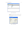
Create or Open a WinDriver Project . . . . . . . . . . .
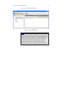
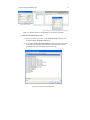
Select Your Plug-and-Play Device . . . . . . . . . . . .
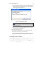
DriverWizard INF File Information . . . . . . . . . . . .
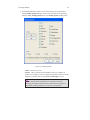
PCI Resources . . . . . . . . . . . . . . . . . . . . . . .
Define Registers . . . . . . . . . . . . . . . . . . . . . .
Read/Write Memory and I/O . . . . . . . . . . . . . . .
Listen to Interrupts . . . . . . . . . . . . . . . . . . . .
Define Transfer Commands for Level-Sensitive Interrupts
Code Generation Options . . . . . . . . . . . . . . . . .
Additional Driver Options . . . . . . . . . . . . . . . .
.
.
.
.
.
.
.
.
.
.
.
.
.
.
.
.
.
.
.
.
.
.
.
.
.
.
.
.
.
.
.
.
.
.
.
.
.
.
.
.
.
.
.
.
.
.
.
.
.
.
.
.
.
.
.
.
.
.
.
.
.
.
.
.
.
.
.
.
.
.
50
50
52
54
54
55
56
57
57
58
6.1
6.2
6.3
6.4
Start Debug Monitor . . . . . . . . . . .
Debug Options . . . . . . . . . . . . . .
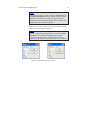
wddebug Windows CE Start Log Message
wddebug Windows CE Stop Log Message
.
.
.
.
.
.
.
.
.
.
.
.
.
.
.
.
.
.
.
.
.
.
.
.
.
.
.
.
68
69
75
75
.
.
.
.
.
.
.
.
.
.
.
.
.
.
.
.
.
.
.
.
.
.
.
.
.
.
.
.
.
.
.
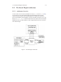
.
11.1 Kernel PlugIn Architecture . . . . . . . . . . . . . . . . . . . . . . . 113
11.2 Interrupt Handling Without Kernel PlugIn . . . . . . . . . . . . . . . 133
11.3 Interrupt Handling With the Kernel PlugIn . . . . . . . . . . . . . . . 134
13
Chapter 1
WinDriver Overview
In this chapter you will explore the uses of WinDriver, and learn the basic steps of
creating your driver.
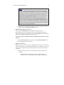
NOTE
This manual outlines WinDriver’s support for PCI / PCMCIA / CardBus / ISA /
EISA / CompactPCI / PCI Express devices.
WinDriver also supports the Universal Serial Bus (USB). For detailed information
regarding WinDriver USB, please refer to the WinDriver Product Line page on our
web site (http://www.jungo.com/st/windriver.html) and to the WinDriver
USB Manual, which is available on-line at: http://www.jungo.com/st/
support/support_windriver.html.
1.1 Introduction to WinDriver
WinDriver is a development toolkit that dramatically simplifies the difficult
task of creating device drivers and hardware access applications. WinDriver
includes a wizard and code generation features that automatically detect your
hardware and generate the driver to access it from your application. The driver
and application you develop using WinDriver is source code compatible across all
supported operating systems [1.7]. The driver is binary compatible across Windows
Vista / Server 2008 / Server 2003 / XP / 2000. Bus architecture support includes
PCI/PCMCIA/CardBus/ISA/EISA/CompactPCI/PCI Express (PCMCIA is supported
only on Windows Vista/Server 2008/Server 2003/XP/2000). WinDriver provides a
complete solution for creating high-performance drivers.
14
1.2 Background
15
Don’t let the size of this manual fool you. WinDriver makes developing device
drivers an easy task that takes hours instead of months. Most of this manual deals
with the features that WinDriver offers to the advanced user. However, most
developers will find that reading this chapter and glancing through the DriverWizard
and function reference chapters is all they need to successfully write their driver.
WinDriver supports development for all PCI / PCMCIA / CardBus / ISA / EISA /
CompactPCI / PCI Express chipsets. Enhanced support is offered for PLX, Altera,
AMCC and Xilinx PCI chipsets, as outlined in Chapter 7 of the manual.
Chapter 10 explains how to tune your driver code to achieve optimal performance,
with special emphasis on WinDriver’s Kernel PlugIn feature. This feature allows the
developer to write and debug the entire device driver in the user mode, and later drop
performance critical portions of the code into kernel mode. In this way the driver
achieves optimal kernel-mode performance, while the developer need not sacrifice
the ease of user-mode development. For a detailed overview of the Kernel PlugIn,
refer to Chapters 11 – 12.
Visit Jungo’s web site at http://www.jungo.com for the latest news about
WinDriver and other driver development tools that Jungo offers.
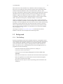
1.2 Background
1.2.1 The Challenge
In protected operating systems such as Windows and Linux, a programmer cannot
access hardware directly from the application level (user mode), where development
work is usually done. Hardware can only be accessed from within the operating
system itself (kernel mode or Ring-0), utilizing software modules called device
drivers. In order to access a custom hardware device from the application level, a
programmer must do the following:
• Learn the internals of the operating system he is working on.
• Learn how to write a device driver.
• Learn new tools for developing/debugging in kernel mode (WDK, ETK,
DDI/DKI).
• Write the kernel-mode device driver that does the basic hardware input/output.
• Write the application in user mode that accesses the hardware through the
device driver written in kernel mode.
• Repeat the first four steps for each new operating system on which the code
should run.
1.2 Background
16
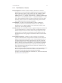
1.2.2 The WinDriver Solution
Easy Development: WinDriver enables Windows, Windows CE, and Linux
programmers to create PCI/PCMCIA/CardBus/ISA/EISA/CompactPCI/PCI
Express based device drivers in an extremely short time. WinDriver allows
you to create your driver in the familiar user-mode environment, using
MSDEV/Visual C/C++, MSDEV .NET, Borland C++ Builder, Borland Delphi,
Visual Basic 6.0, MS eMbedded Visual C++, MS Platform Builder C++, GCC,
or any other appropriate compiler. You do not need to have any device driver
knowledge, nor do you have to be familiar with operating system internals,
kernel programming, the WDK, ETK or DDI/DKI.
Cross Platform: The driver created with WinDriver will run on Windows
Vista/Server 2008/Server 2003/XP/2000, Windows CE.NET, Windows
Embedded CE v6.00, Windows Mobile 5.0/6.0 and Linux. In other words –
write it once, run it on many platforms.
Friendly Wizards: DriverWizard (included) is a graphical diagnostics tool that lets
you view/define the device’s resources and test the communication with the
hardware with just a few mouse clicks, before writing a single line of code.
Once the device is operating to your satisfaction, DriverWizard creates the
skeletal driver source code, giving access functions to all the resources on the
hardware.
Kernel-Mode Performance: WinDriver’s API is optimized for performance.
For drivers that need kernel-mode performance, WinDriver offers the Kernel
PlugIn. This powerful feature enables you to create and debug your code in
user mode and run the performance-critical parts of your code (such as the
interrupt handling or access to I/O mapped memory ranges) in kernel mode,
thereby achieving kernel-mode performance (zero performance degradation).
This unique feature allows the developer to run user-mode code in the OS
kernel without having to learn how the kernel works. For a detailed overview
of this feature, see Chapter 11.
Kernel PlugIn is not implemented under Windows CE. In this operating system
there is no separation between kernel mode and user mode, therefore top
performance can be achieved without using the Kernel PlugIn.
To improve the interrupt handling rate on Windows CE, follow the instructions
in section 9.2.8.1 of the manual.
1.3 How Fast Can WinDriver Go?
17
1.3 How Fast Can WinDriver Go?
You can expect the same throughput using the WinDriver Kernel PlugIn as when
using a custom kernel driver. Throughput is constrained only by the limitations of
your operating system and hardware. A rough estimate of the throughput you can
obtain using the Kernel PlugIn is approximately 100,000 interrupts per second.
1.4 Conclusion
Using WinDriver, a developer need only do the following to create an application that
accesses the custom hardware:
• Start DriverWizard and detect the hardware and its resources.
• Automatically generate the device driver code from within DriverWizard,
or use one of the WinDriver samples as the basis for the application (see
Chapter 7 for an overview of WinDriver’s enhanced support for specific
chipsets).
• Modify the user-mode application, as needed, using the generated/sample
functions to implement the desired functionality for your application.
Your hardware access application will run on all the supported platforms [1.7] – just
re-compile the code for the target platform. (The code is binary compatible across
Windows Vista/Server 2008/Server 2003/XP/2000 platforms, so there is no need to
rebuild the code when porting the driver between these operating systems.)
1.5 WinDriver Benefits
18
1.5 WinDriver Benefits
• Easy user-mode driver development.
• Kernel PlugIn for high-performance drivers.
• Friendly DriverWizard allows hardware diagnostics without writing a single
line of code.
• Automatically generates the driver code for the project in C, C#, Delphi
(Pascal) or Visual Basic.
• Supports any PCI/PCMCIA/CardBus/ISA/EISA/CompactPCI/PCI Express
device, regardless of manufacturer.
• Enhanced support for PLX, Altera, AMCC and Xilinx chipsets frees the
developer from the need to study the hardware’s specification.
• Applications are binary-compatible across Windows Vista / Server 2008 /
Server 2003 / XP / 2000.
• Applications are source code compatible across all supported operating systems
– Windows Vista/Server 2008/Server 2003/XP/2000, Windows CE.NET,
Windows Embedded CE v6.00, Windows Mobile 5.0/6.0 and Linux.
• Can be used with common development environments, including
MSDEV/Visual C/C++, MSDEV .NET, Borland C++ Builder, Borland Delphi,
Visual Basic 6.0, MS eMbedded Visual C++, MS Platform Builder C++, GCC,
or any other appropriate compiler.
• No WDK, ETK, DDI or any system-level programming knowledge required.
• Supports I/O, DMA, interrupt handling and access to memory-mapped cards.
• Supports multiple CPUs and multiple PCI bus platforms (PCI / PCMCIA /
CardBus / ISA / EISA / CompactPCI / PCI Express).
• Supports 64-bit PCI data transfers.
• Includes dynamic driver loader.
• Comprehensive documentation and help files.
• Detailed examples in C, C#, Delphi and Visual Basic 6.0.
• WHQL certifiable driver (Windows).
• Two months of free technical support.
• No run-time fees or royalties.
1.6 WinDriver Architecture
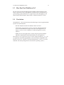
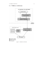
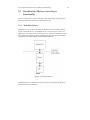
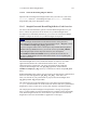
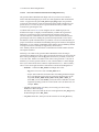
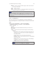
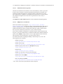
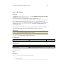
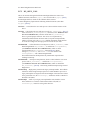
1.6 WinDriver Architecture
Figure 1.1: WinDriver Architecture
19
1.7 What Platforms Does WinDriver Support?
20
For hardware access, your application calls one of the WinDriver user-mode
functions. The user-mode function calls the WinDriver kernel, which accesses the
hardware for you through the native calls of the operating system.
WinDriver’s design minimizes performance hits on your code, even though it is
running in user mode. However, some hardware drivers have high performance
requirements that cannot be achieved in user mode. This is where WinDriver’s edge
sharpens. After easily creating and debugging your code in user mode, you may
drop the performance-critical modules of your code (such as a hardware interrupt
handler) into the WinDriver Kernel PlugIn without changing them at all. Now, the
WinDriver kernel calls this module from kernel mode, thereby achieving maximal
performance. This allows you to program and debug in user mode, and still achieve
kernel performance where needed. For a detailed overview of the Kernel PlugIn
feature, see Chapter 11.
Kernel PlugIn is not implemented under Windows CE. In this operating system there
is no separation between kernel mode and user mode, therefore top performance can
be achieved without using the Kernel PlugIn.
To improve the interrupt handling rate on Windows CE, follow the instructions in
section 9.2.8.1 of the manual.
1.7 What Platforms Does WinDriver Support?
WinDriver supports the following operating systems:
• Windows Vista/Server 2008/Server 2003/XP/2000 – henceforth collectively:
”Windows”.
• Windows CE 4.x – 5.x (Windows CE.NET), Windows Embedded CE v6.00,
Windows Mobile 5.0/6.0 – henceforth collectively: ”Windows CE”.
• Linux
Support for Windows NT 4.0, Solaris, and VxWorks is available in earlier versions.
The same source code will run on all supported platforms – simply re-compile
it for the target platform. The source code is binary compatible across Windows
Vista/Server 2008/Server 2003/XP/2000, so executables created with WinDriver can
be ported among these operating systems without re-compilation.
Even if your code is meant only for one of the supported operating systems, using
WinDriver will give you the flexibility to move your driver to another operating
system in the future without needing to change your code.
1.8 Limitations of the Different Evaluation Versions
21
1.8 Limitations of the Different Evaluation Versions
All the evaluation versions of WinDriver are full featured. No functions are limited or
crippled in any way. The evaluation version of WinDriver varies from the registered
version in the following ways:
• Each time WinDriver is activated, an Un-registered message appears.
• When using the DriverWizard, a dialogue box with a message stating that an
evaluation version is being run appears on every interaction with the hardware.
• In the Linux and Windows CE versions, the driver will remain operational for
60 minutes, after which time it must be restarted.
• The Windows evaluation version expires 30 days from the date of installation.
For more details please refer to appendix D.
1.9 How Do I Develop My Driver with WinDriver?
1.9.1 On Windows and Linux
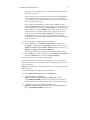
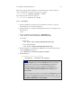
1. Start DriverWizard and use it to diagnose your hardware – see details in
Chapter 4.
2. Let DriverWizard generate skeletal code for your driver, or use one of the
WinDriver samples as the basis for your driver application (see Chapter [7]
for details regarding WinDriver’s enhanced support for specific chipsets).
3. Modify the generated/sample code to suit your application’s needs.
4. Run and debug your driver in the user mode.
5. If your code contains performance-critical sections, refer to Chapter 10 for
suggestions on how to improve your driver’s performance.
NOTE
The code generated by DriverWizard is a diagnostics program that contains
functions that read and write to any resource detected or defined (including
custom-defined registers), enables your card’s interrupts, listens to them, and more.
1.10 What Does the WinDriver Toolkit Include?
22
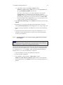
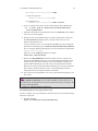
1.9.2 On Windows CE
1. Plug your hardware into a Windows host machine.
2. Diagnose your hardware using DriverWizard.
3. Let DriverWizard generate your driver’s skeletal code.
4. Modify this code using eMbedded Visual C++ to meet your specific needs. If
you are using Platform Builder, activate it and insert the generated *.pbp into
your workspace.
5. Test your driver on the target embedded Windows CE platorm.
TIP
If you cannot plug your hardware into a Windows host machine, you can still
use DriverWizard to generate code for your device by manually entering all your
resources in the wizard. Let DriverWizard generate your code and then test it
on your hardware using a serial connection. After verifying that the generated
code works properly, modify it to meet your specific needs. You may also use (or
combine) any of the sample files for your driver’s skeletal code.
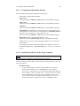
1.10 What Does the WinDriver Toolkit Include?
• A printed version of this manual
• Two months of free technical support (Phone/Fax/Email)
• WinDriver modules
• The WinDriver CD
– Utilities
– Chipset support APIs
– Sample files
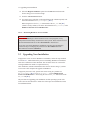
1.10 What Does the WinDriver Toolkit Include?
23
1.10.1 WinDriver Modules
• WinDriver (WinDriver/include) – the general purpose hardware access toolkit.
The main files here are:
– windrvr.h: Declarations and definitions of WinDriver’s basic API.
– wdc_lib.h and wdc_defs.h: Declarations and definitions of the WinDriver
Card (WDC) library, which provides convenient wrapper APIs for
accessing PCI/PCMCIA/CardBus/ISA/EISA/CompactPCI/PCI Express
devices (see Chapter B.2).
– windrvr_int_thread.h: Declarations of convenient wrapper functions to
simplify interrupt handling.
– windrvr_events.h: Declarations of APIs for handling and Plug-and-Play
and power management events.
– utils.h: Declarations of general utility functions.
– status_strings.h: Declarations of API for converting WinDriver status
codes to descriptive error strings.
• DriverWizard (WinDriver/wizard/wdwizard) – a graphical tool that diagnoses
your hardware and enables you to easily generate code for your driver (refer to
Chapter 4 for details).
• Debug Monitor – a debugging tool that collects information about your
driver as it runs. This tool is available both as a fully graphical application
(WinDriver/util/wddebug_gui) and as a console-mode application
(WinDriver/util/wddebug). The console-mode version also supports GUI
execution on Windows CE platforms that don’t have a command-line prompt.
For details regarding the Debug Monitor, refer to section 6.2.
• WinDriver distribution package (WinDriver/redist) – the files you include in
the driver distribution to customers.
• WinDriver Kernel PlugIn – the files and samples needed to create a
kernel-mode Kernel PlugIn driver (refer to Chapter 11 for details.)
• This manual – the full WinDriver manual (this document), in different formats,
can be found under the WinDriver/docs directory.
1.10 What Does the WinDriver Toolkit Include?
24
1.10.2 Utilities
• pci_dump.exe (WinDriver/util/pci_dump.exe) – used to obtain a dump of the
PCI configuration registers of the installed PCI cards.
• pci_diag.exe (WinDriver/util/pci_diag.exe) – used for reading/writing PCI
configuration registers, accessing PCI I/O and memory ranges and handling
PCI interrupts.
• pci_scan.exe (WinDriver/util/pci_scan.exe) – used to obtain a list of the PCI
cards installed and the resources allocated for each card.
• pcmcia_diag.exe (WinDriver/util/pcmcia_diag.exe) – used for
reading/writing PCMCIA attribute space, accessing PCMCIA I/O and memory
ranges and handling PCMCIA interrupts.
• pcmcia_scan.exe (WinDriver/util/pcmcia_scan.exe) – used to obtain a list of
the PCMCIA cards installed and the resources allocated for each card.
1.10.3 WinDriver’s Specific Chipset Support
WinDriver provides custom wrapper APIs and sample code for major PCI chipsets
(see Chapter 7), including for the following chipsets:
• PLX 6466, 9030, 9050, 9052, 9054, 9056, 9080 and 9656 – WinDriver/plx
• AMCC S5933 – WinDriver/amcc
• Altera pci_dev_kit – WinDriver/altera/pci_dev_kit
• Xilinx VirtexII and Virtex 5 – WinDriver/xilinx/
1.10.4 Samples
In addition to the samples provided for specific chipsets [1.10.3], WinDriver includes
a variety of samples that demonstrate how to use WinDriver’s API to communicate
with your device and perform various driver tasks.
• C samples: found under the WinDriver/samples directory.
These samples also include the source code for the utilities listed
above [1.10.2].
• .NET C# samples (Windows): found under the WinDriver\csharp.net
directory.
• Delphi (Pascal) samples (Windows) WinDriver\delphi\samples directory.
• Visual Basic samples (Windows): found under the WinDriver\vb\samples
directory.
1.11 Can I Distribute the Driver Created with WinDriver?
25
1.11 Can I Distribute the Driver Created with
WinDriver?
Yes. WinDriver is purchased as a development toolkit, and any device driver created
using WinDriver may be distributed, royalties free, in as many copies as you wish.
See the license agreement (WinDriver/docs/license.pdf) for more details.
Chapter 2
Understanding Device Drivers
This chapter provides you with a general introduction to device drivers and takes you
through the structural elements of a device driver.
NOTE
Using WinDriver, you do not need to familiarize yourself with the internal workings
of driver development. As explained in Chapter 1 of the manual, WinDriver enables
you to communicate with your hardware and develop a driver for your device from
the user mode, using only WinDriver’s simple APIs, without any need for driver or
kernel development knowledge.
2.1 Device Driver Overview
Device drivers are the software segments that provides an interface between the
operating system and the specific hardware devices such as terminals, disks, tape
drives, video cards and network media. The device driver brings the device into
and out of service, sets hardware parameters in the device, transmits data from the
kernel to the device, receives data from the device and passes it back to the kernel,
and handles device errors.
A driver acts like a translator between the device and programs that use the device.
Each device has its own set of specialized commands that only its driver knows. In
contrast, most programs access devices by using generic commands. The driver,
therefore, accepts generic commands from a program and then translates them into
specialized commands for the device.
26
2.2 Classification of Drivers According to Functionality
2.2 Classification of Drivers According to
Functionality
There are numerous driver types, differing in their functionality. This subsection
briefly describes three of the most common driver types.
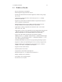
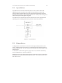
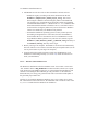
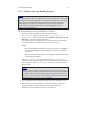
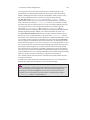
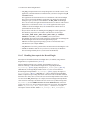
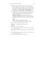
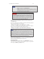
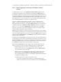
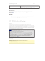
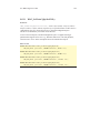
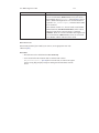
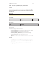
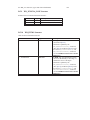
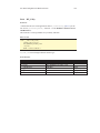
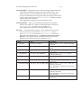
2.2.1 Monolithic Drivers
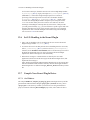
Monolithic drivers are device drivers that embody all the functionality needed to
support a hardware device. A monolithic driver is accessed by one or more user
applications, and directly drives a hardware device. The driver communicates with
the application through I/O control commands (IOCTLs) and drives the hardware
using calls to the different WDK, ETK, DDI/DKI functions.
Figure 2.1: Monolithic Drivers
Monolithic drivers are supported in all operating systems including all Windows
platforms and all Unix platforms.
27
2.2 Classification of Drivers According to Functionality
28
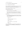
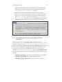
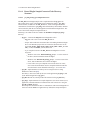
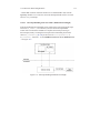
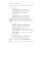
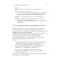
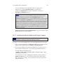
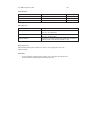
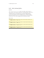
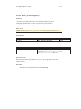
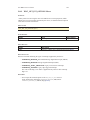
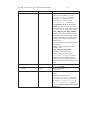
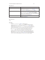
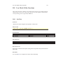
2.2.2 Layered Drivers
Layered drivers are device drivers that are part of a stack of device drivers that
together process an I/O request. An example of a layered driver is a driver that
intercepts calls to the disk and encrypts/decrypts all data being transferred to/from
the disk. In this example, a driver would be hooked on to the top of the existing driver
and would only do the encryption/decryption.
Layered drivers are sometimes also known as filter drivers, and are supported in all
operating systems including all Windows platforms and all Unix platforms.
Figure 2.2: Layered Drivers
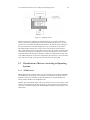
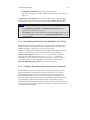
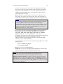
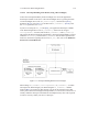
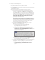
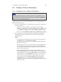
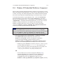
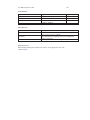
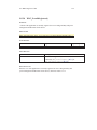
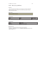
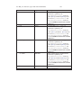
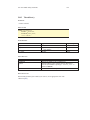
2.2.3 Miniport Drivers
A Miniport driver is an add-on to a class driver that supports miniport drivers. It is
used so the miniport driver does not have to implement all of the functions required
of a driver for that class. The class driver provides the basic class functionality for the
miniport driver.
A class driver is a driver that supports a group of devices of common functionality,
such as all HID devices or all network devices.
Miniport drivers are also called miniclass drivers or minidrivers, and are supported in
the Windows NT (2000) family, namely Windows Vista / Server 2008 / Server 2003 /
XP / 2000 / NT 4.0.
2.3 Classification of Drivers According to Operating Systems
29
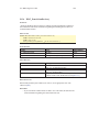
Figure 2.3: Miniport Drivers
Windows Vista/Server 2008/Server 2003/XP/2000/NT 4.0 provide several driver
classes (called ports) that handle the common functionality of their class. It is then
up to the user to add only the functionality that has to do with the inner workings of
the specific hardware. The NDIS miniport driver is one example of such a driver.
The NDIS miniport framework is used to create network drivers that hook up to
NT’s communication stacks, and are therefore accessible to common communication
calls used by applications. The Windows NT kernel provides drivers for the various
communication stacks and other code that is common to communication cards. Due
to the NDIS framework, the network card developer does not have to write all of this
code, only the code that is specific to the network card he is developing.
2.3 Classification of Drivers According to Operating
Systems
2.3.1 WDM Drivers
WDM (Windows Driver Model) drivers are kernel-mode drivers within the Windows
NT and Windows 98 operating system families. The Windows NT family includes
Windows Vista/Server 2008/Server 2003/XP/2000/NT 4.0, and the Windows 98
family includes Windows 98 and Windows Me.
WDM works by channeling some of the work of the device driver into portions of the
code that are integrated into the operating system. These portions of code handle all
of the low-level buffer management, including DMA and Plug-and-Play (Pnp) device
enumeration.
2.3 Classification of Drivers According to Operating Systems
30
WDM drivers are PnP drivers that support power management protocols, and include
monolithic drivers, layered drivers and miniport drivers.
2.3.2 VxD Drivers
VxD drivers are Windows 95/98/Me Virtual Device Drivers, often called VxDs
because the file names end with the .vxd extension. VxD drivers are typically
monolithic in nature. They provide direct access to hardware and privileged operating
system functions. VxD drivers can be stacked or layered in any fashion, but the driver
structure itself does not impose any layering.
2.3.3 Unix Device Drivers
In the classic Unix driver model, devices belong to one of three categories: character
(char) devices, block devices and network devices. Drivers that implement these
devices are correspondingly known as char drivers, block drivers or network drivers.
Under Unix, drivers are code units linked into the kernel that run in privileged kernel
mode. Generally, driver code runs on behalf of a user-mode application. Access to
Unix drivers from user-mode applications is provided via the file system. In other
words, devices appear to the applications as special device files that can be opened.
Unix device drivers are either layered or monolithic drivers. A monolithic driver can
be perceived as a one-layer layered driver.
2.3.4 Linux Device Drivers
Linux device drivers are based on the classic Unix device driver model. In addition,
Linux introduces some new characteristics.
Under Linux, a block device can be accessed like a character device, as in Unix, but
also has a block-oriented interface that is invisible to the user or application.
Traditionally, under Unix, device drivers are linked with the kernel, and the system is
brought down and restarted after installing a new driver. Linux introduces the concept
of a dynamically loadable driver called a module. Linux modules can be loaded or
removed dynamically without requiring the system to be shut down. A Linux driver
can be written so that it is statically linked or written in a modular form that allows
it to be dynamically loaded. This makes Linux memory usage very efficient because
modules can be written to probe for their own hardware and unload themselves if they
cannot find the hardware they are looking for.
Like Unix device drivers, Linux device drivers are either layered or monolithic
drivers.
2.4 The Entry Point of the Driver
31
2.4 The Entry Point of the Driver
Every device driver must have one main entry point, like the main() function in a
C console application. This entry point is called DriverEntry() in Windows and
init_module() in Linux. When the operating system loads the device driver, this
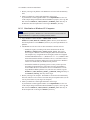
driver entry procedure is called.
There is some global initialization that every driver needs to perform only once when
it is loaded for the first time. This global initialization is the responsibility of the
DriverEntry()/init_module() routine. The entry function also registers which
driver callbacks will be called by the operating system. These driver callbacks are
operating system requests for services from the driver. In Windows, these callbacks
are called dispatch routines, and in Linux they are called file operations. Each
registered callback is called by the operating system as a result of some criteria, such
as disconnection of hardware, for example.
2.5 Associating the Hardware to the Driver
Operating systems differ in how they link a device to its driver.
In Windows, the link is performed by the INF file, which registers the device to work
with the driver. This association is performed before the DriverEntry() routine is
called. The operating system recognizes the device, looks up in its database which
INF file is associated with the device, and according to the INF file, calls the driver’s
entry point.
In Linux, the link between a device and its driver is defined in the init_module()
routine. The init_module() routine includes a callback which states what hardware
the driver is designated to handle. The operating system calls the driver’s entry point,
based on the definition in the code.
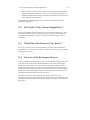
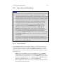
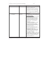
2.6 Communicating with Drivers
A driver can create an instance, thus enabling an application to open a handle to the
driver through which the application can communicate with it.
The applications communicate with the drivers using a file access API (Application
Program Interface). Applications open a handle to the driver using CreateFile()
call (in Windows), or open() call (in Linux) with the name of the device as the file
name. In order to read from and write to the device, the application calls ReadFile()
and WriteFile() (in Windows), or read(), write() in Linux.
2.6 Communicating with Drivers
32
Sending requests is accomplished using an I/O control call, called
DeviceIoControl() (in Windows), and ioctl() in Linux. In this I/O control call,
the application specifies:
• The device to which the call is made (by providing the device’s handle).
• An IOCTL code that describes which function this device should perform.
• A buffer with the data on which the request should be performed.
The IOCTL code is a number that the driver and the requester agree upon for a
common task.
The data passed between the driver and the application is encapsulated into a
structure. In Windows, this structure is called an I/O Request Packet (IRP), and is
encapsulated by the I/O Manager. This structure is passed on to the device driver,
which may modify it and pass it down to other device drivers.
Chapter 3
Installing WinDriver
This chapter takes you through the process of installing WinDriver on your
development platform, and shows you how to verify that your WinDriver is properly
installed. The last section discusses the uninstall procedure. To find out how to install
the driver you create on target platforms, refer to Chapter 14.
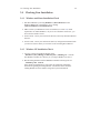
3.1 System Requirements
3.1.1 Windows System Requirements
• Any x86 32-bit or 64-bit (x64: AMD64 or Intel EM64T) processor.
• Any development environment supporting C, .NET, VB or Delphi.
• Windows 2000 requires SP4.
• Windows XP requires SP2.
33
3.1 System Requirements
34
3.1.2 Windows CE System Requirements
• An x86 / MIPS / ARM Windows CE 4.x – 5.x (Windows CE.NET) or
Windows Embedded CE v6.00 target platform
or:
an ARMV4I Windows Mobile 5.0/6.0 target platform.
• Windows Vista/Server 2008/Server 2003/XP/2000 host development platform.
• For Windows CE 4.x – 5.0: Microsoft eMbedded Visual C++ with
a corresponding target SDK OR Microsoft Platform Builder with a
corresponding BSP (Board Support Package) for the target platform.
For Windows Embedded CE 6.0: Microsoft Visual Studio (MSDEV) .NET
with the Windows CE 6.0 plugin.
For Windows Mobile: Microsoft Visual Studio (MSDEV) .NET 2005/2008.
3.1.3 Linux System Requirements
• Any 32-bit x86 processor with a Linux 2.2.x, 2.4.x or 2.6.x kernel
or:
Any 64-bit x86 AMD64 or Intel EM64T (x86_64) processor with a Linux 2.4.x
or 2.6.x kernel
or:
Any PowerPC 32-bit processor with a Linux 2.4.x or 2.6.x kernel
or:
Any PowerPC 64-bit processor with a Linux 2.6.x kernel
NOTE
Jungo strives to support new Linux kernel versions as close as possible to
their release. To find out the latest supported kernel version, refer to the latest
WinDriver release notes (online: http://www.jungo.com/st/wdver.html).
• A GCC compiler.
NOTE
The version of the GCC compiler should match the compiler version used for
building the running Linux kernel.
• Any 32-bit or 64-bit development environment (depending on your target
configuration) supporting C for user mode.
• On your development PC: glibc2.3.x.
• libstdc++.so.5 is required for running GUI WinDriver applications (e.g.
DriverWizard [4] ; Debug Monitor [6.2]).
3.2 WinDriver Installation Process
35
3.2 WinDriver Installation Process
The WinDriver CD contains all versions of WinDriver for the supported operating
systems. The CD’s root directory contains the Windows Vista / Server 2008 / Server
2003 / XP / 2000 version. The installation of this version will begin automatically
when you insert the CD into the CD drive on your Windows development machine.
The other versions of WinDriver are located in <OS>/ sub-directories (for example:
Linux/ ; Wince/).
3.2.1 Windows WinDriver Installation Instructions
NOTE
Driver installation on Windows requires administrator privileges.
1. Insert the WinDriver CD into your CD-ROM drive.
When installing WinDriver by downloading it from Jungo’s web site instead
of using the WinDriver CD, double click the downloaded installation file –
WD1002.EXE – and go to step 3.
2. Wait a few seconds until the installation program starts automatically. If for
some reason it does not start automatically, double-click the file WD1002.EXE
and click the Install WinDriver button.
3. Read the license agreement carefully, and click Yes if you accept its terms.
4. Choose the destination location in which to install WinDriver.
5. In the Setup Type screen, choose one of the following:
• Typical – install all WinDriver modules (generic WinDriver toolkit +
specific chipset APIs).
• Compact – install only the generic WinDriver toolkit.
• Custom – select which WinDriver modules to install.
6. After the installer finishes copying the required files, choose whether to view
the Quick Start guides.
7. You may be prompted to reboot your computer.
NOTE
The WinDriver installation defines a WD_BASEDIR environment variable, which
is set to point to the location of your WinDriver directory, as selected during the
installation. This variable is used during the DriverWizard [4] code generation – it
determines the default directory for saving your generated code and is used in the
include paths of the generated project/make files. This variable is also used in the
sample Kernel PlugIn projects and makefiles.
3.2 WinDriver Installation Process
36
The following steps are for registered users only:
In order to register your copy of WinDriver with the license you received from Jungo,
follow the steps below:
8. Start DriverWizard: Start | Programs | WinDriver | DriverWizard.
9. Select the Register WinDriver option from the File menu and insert the
license string you received from Jungo. Click the Activate License button.
10. To register source code that you developed during the evaluation period, refer
to the documentation of WDC_DriverOpen() [B.3.2].
When using the low-level WD_xxx API instead of the WDC_xxx API [B.2]
(which is used by default), refer to the documentation of WD_License() in the
WinDriver PCI Low-Level API Reference.
3.2.2 Windows CE WinDriver Installation Instructions
3.2.2.1 Installing WinDriver CE when Building New CE-Based Platforms
NOTES
• The following instructions apply to platform developers who build Windows
CE kernel images using Windows CE Platform Builder or using MSDEV
2005/2008 with the Windows CE 6.0 plugin. The instructions use the notation
”Windows CE IDE” to refer to either of these platforms.
• We recommend that you read Microsoft’s documentation and understand the
Windows CE and device driver integration procedure before you perform the
installation.
1. Modify the project registry file to add an entry for your target device:
• If you select to use the WinDriver component (see step 2), modify
WinDriver\samples\wince_install\<TARGET_CPU>\WinDriver.reg
(e.g., WinDriver\samples\wince_install\ARMV4I\WinDriver.reg).
• Otherwise, modify WinDriver\samples\wince_install\project_wd.reg.
2. You can simplify the driver integration into your Windows CE platform by
following the procedure described in this step before the Sysgen platform
compilation stage.
NOTE:
• The procedure described in this step is relevant only for developers who
use Windows CE 4.x-5.x with Platform Builder.
3.2 WinDriver Installation Process
37
Developers who use Windows CE 6.x with MSDEV 2005/2008 should
skip to the next step [3].
• This procedure provides a convenient method for integrating WinDriver
into your Windows CE platform. If you select not to use this method,
you will need to perform the manual integration steps described in step 4
below after the Sysgen stage.
• The procedure described in this step also adds the WinDriver kernel
module (windrvr6.dll) to your OS image. This is a necessary step if you
want the WinDriver CE kernel file (windrvr6.dll) to be a permanent part
of the Windows CE image (NK.BIN), which is the case if you select to
transfer the file to your target platform using a floppy disk. However,
if you prefer to have the file windrvr6.dll loaded on demand via the
CESH/PPSH services, you need to perform the manual integration
method described in step 4 instead of performing the procedure described
in the present step.
(a) Run the Windows CE IDE and open your platform.
(b) From the File menu select Manage Catalog Items.... and then click
the Import... button and select the WinDriver.cec file from the relevant
WinDriver\samples\wince_install\<TARGET_CPU>\ directory (e.g.
WinDriver\samples\wince_install\ARMV4I\).
This will add a WinDriver component to the Platform Builder Catalog.
(c) In the Catalog view, right-click the mouse on the WinDriver Component
node in the Third Party tree and select Add to OS design.
3. Compile your Windows CE platform (Sysgen stage).
4. If you did not perform the procedure described in step 2 above, perform the
following steps after the Sysgen stage in order to manually integrate the driver
into your platform.
NOTE: If you followed the procedure described in step 2, skip this step and go
directly to step 5.
(a) Run the Windows CE IDE and open your platform.
(b) Select Open Release Directory from the Build menu.
(c) Copy the WinDriver CE kernel file –
WinDriver\redist\<TARGET_CPU>\windrvr6.dll – to the
%_FLATRELEASEDIR% sub-directory on the target development
platform (should be the current directory in the new command window).
(d) Append the contents of the project_wd.reg file in the
WinDriver\samples\wince_install\ directory to the project.reg file in
the %_FLATRELEASEDIR% sub-directory.
3.2 WinDriver Installation Process
38
(e) Append the contents of the project_wd.bib file in the
WinDriver\samples\wince_install\ directory to the project.bib file in
the %_FLATRELEASEDIR% sub-directory.
This step is only necessary if you want the WinDriver CE kernel file
(windrvr6.dll) to be a permanent part of the Windows CE image
(NK.BIN), which is the case if you select to transfer the file to your target
platform using a floppy disk. If you prefer to have the file windrvr6.dll
loaded on demand via the CESH/PPSH services, you do not need to carry
out this step until you build a permanent kernel.
5. Select Make Run-Time Image from the Build menu and name the new image
NK.BIN.
6. Download your new kernel to the target platform and initialize it either by
selecting Download/Initialize from the Target menu or by using a floppy disk.
7. Restart your target CE platform. The WinDriver CE kernel will automatically
load.
8. Compile and run the sample programs to make sure that WinDriver CE is
loaded and is functioning correctly (see section 3.4.2, which describes how
to check your installation).
3.2.2.2 Installing WinDriver CE when Developing Applications for Windows
CE Computers
NOTE
Unless otherwise specified, ”Windows CE” references in this section include all
supported Windows CE platforms, including Windows Mobile.
The following instructions apply to driver developers who do not build the Windows
CE kernel, but only download their drivers, built using Microsoft eMbedded Visual
C++ (Windows CE 4.x – 5.x) or MSDEV .NET 2005/2008 (Windows Mobile or
Windows CE 6.x) to a ready-made Windows CE platform:
1. Insert the WinDriver CD into your Windows host CD drive.
2. Exit the automatic installation.
3. Copy WinDriver’s kernel module – windrvr6.dll – from the
WinDriver\redist\WINCE\<TARGET_CPU> directory on the Windows
host development PC to the Windows\ directory on your target Windows CE
platform.
3.2 WinDriver Installation Process
39
4. Add WinDriver to the list of device drivers Windows CE loads on boot:
• Modify the registry according to the entries documented in the file
WinDriver\samples\wince_install\ project_wd.reg. This can be
done using the Windows CE Pocket Registry Editor on the hand-held
CE computer or by using the Remote CE Registry Editor Tool supplied
with MS eMbedded Visual C++ (Windows CE 4.x – 5.x) / MSDEV .NET
2005/2008 (Windows Mobile or Windows CE 6.x). Note that in order to
use the Remote CE Registry Editor tool you will need to have Windows
CE Services installed on your Windows host platform.
• On Windows Mobile the operating system’s security scheme prevents
the loading of unsigned drivers at boot time, therefore the WinDriver
kernel module has to be reloaded after boot. To load WinDriver on the
target Windows Mobile platform every time the OS is started, copy the
WinDriver\redist\Windows_Mobile_5_ARMV4I\ wdreg.exe utility to
the Windows\StartUp\ directory on the target.
5. Restart your target CE computer. The WinDriver CE kernel will automatically
load. You will have to do a warm reset rather than just suspend/resume (use the
reset or power button on your target CE computer).
6. Compile and run the sample programs to make sure that WinDriver CE is
loaded and is functioning correctly (see section 3.4, which describes how to
check your installation).
3.2.2.3 Windows CE Installation Note
The WinDriver installation on the host Windows Vista / Server 2008 / Server 2003
/ XP / 2000 PC defines a WD_BASEDIR environment variable, which is set to point
to the location of your WinDriver directory, as selected during the installation. This
variable is used during the DriverWizard [4] code generation – it determines the
default directory for saving your generated code and is used in the include paths of
the generated project/make files.
Note that if you install the WinDriver Windows Vista / Server 2008 / Server 2003 /
XP / 2000 tool-kit on the same host PC, the installation will override the value of the
WD_BASEDIR variable from the Windows CE installation.
3.2 WinDriver Installation Process
40
3.2.3 Linux WinDriver Installation Instructions
3.2.3.1 Preparing the System for Installation
In Linux, kernel modules must be compiled with the same header files that the kernel
itself was compiled with. Since WinDriver installs kernel modules, it must compile
with the header files of the Linux kernel during the installation process.
Therefore, before you install WinDriver for Linux, verify that the Linux source code
and the file versions.h are installed on your machine:
Install the Linux kernel source code:
• If you have yet to install Linux, install it, including the kernel source code, by
following the instructions for your Linux distribution.
• If Linux is already installed on your machine, check whether the Linux source
code was installed. You can do this by looking for ‘linux’ in the /usr/src
directory. If the source code is not installed, either install it, or reinstall Linux
with the source code, by following the instructions for your Linux distribution.
Install version.h:
• The file version.h is created when you first compile the Linux kernel source
code. Some distributions provide a compiled kernel without the file version.h.
Look under /usr/src/linux/include/linux/ to see if you have this file. If you do
not, please follow these steps:
1. Become super user:
$ su
2. Change directory to the Linux source directory:
# cd /usr/src/linux
3. Type:
# make xconfig
4. Save the configuration by choosing Save and Exit.
5. Type:
# make dep
To run GUI WinDriver applications (e.g., DriverWizard [4] ; Debug Monitor [6.2])
you must also have version 5.0 of the libstdc++ library – libstdc++.so.5. If you do
not have this file, install it from the relevant RPM in your Linux distribution (e.g.,
compat-libstdc++).
3.2 WinDriver Installation Process
41
Before proceeding with the installation, you must also make sure that you have a
‘linux’ symbolic link. If you do not, create one by typing:
/usr/src$ ln -s <target kernel>/ linux
For example, for the Linux 2.4 kernel type:
/usr/src$ ln -s linux-2.4/ linux
3.2.3.2 Installation
1. Insert the WinDriver CD into your Linux machine’s CD drive or copy the
downloaded file to your preferred directory.
2. Change directory to your preferred installation directory, for example to your
home directory:
$ cd ~
3. Extract the WinDriver distribution file – WD1002LN.tgz:
$ tar xvzf /<file location>/WD1002LN.tgz
For example:
• From a CD:
$ tar xvzf /mnt/cdrom/LINUX/WD1002LN.tgz
• From a downloaded file:
$ tar xvzf /home/username/WD1002LN.tgz
4. Change directory to your WinDriver redist/ directory (the tar automatically
creates a WinDriver/ directory):
$ cd <WinDriver directory path>/redist
5. Install WinDriver:
(a) <WinDriver directory>/redist$
./configure --disable-usb-support
NOTE
The configure script creates a makefile based on your specific
running kernel. You may run the configure script based on
another kernel source you have installed, by adding the flag
--with-kernel-source=<path> to the configure script.
The <path> is the full path to the kernel source directory, e.g.
/usr/src/linux.
If the Linux kernel is version 2.6.26 or higher, configure generates
makefiles that use kbuild to compile the kernel modules. You can
force the use of kbuild on earlier versions of Linux, by passing the
--enable-kbuild flag to configure.
3.2 WinDriver Installation Process
42
(b) <WinDriver directory>/redist$ make
(c) Become super user:
<WinDriver directory>/redist$ su
(d) Install the driver:
<WinDriver directory>/redist# make install
6. Create a symbolic link so that you can easily launch the DriverWizard GUI:
$ ln -s <full path to WinDriver>/wizard/wdwizard/
usr/bin/wdwizard
7. Change the read and execute permissions on the file wdwizard so that ordinary
users can access this program.
8. Change the user and group IDs and give read/write permissions to the device
file /dev/windrvr6 depending on how you wish to allow users to access
hardware through the device.
If you are using a Linux 2.6.x kernel that has the udev file system, change the
permissions by modifying your /etc/udev/permissions.d/50-udev.permissions
file. For example, add the following line to provide read and write permissions:
windrvr6:root:root:0666
Otherwise, use the chmod command, for example:
chmod 666 /dev/windrvr6
9. Define a new WD_BASEDIR environment variable and set it to point to the
location of your WinDriver directory, as selected during the installation. This
variable is used in the make and source files of the WinDriver samples and
generated DriverWizard [4] code, and is also used to determine the default
directory for saving your generated DriverWizard project. If you do not define
this variable you will be instructed to do so when attempting to build the
sample/generated code using the WinDriver makefiles.
10. You can now start using WinDriver to access your hardware and generate your
driver code!
TIP
Use the WinDriver/util/wdreg script to load the WinDriver kernel module [13.3].
To automatically load WinDriver on each boot, add the following to the target Linux
boot file (/etc/rc.d/rc.local):
<path to wdreg>/wdreg windrvr6
The following steps are for registered users only
In order to register your copy of WinDriver with the license you received from Jungo,
follow the steps below:
11. Start DriverWizard:
<path to WinDriver>/wizard/wdwizard
3.3 Upgrading Your Installation
43
12. Select the Register WinDriver option from the File menu and insert the
license string you received from Jungo.
13. Click the Activate License button.
14. To register source code that you developed during the evaluation period, refer
to the documentation of WDC_DriverOpen() [B.3.2].
When using the low-level WD_xxx API instead of the WDC_xxx API [B.2]
(which is used by default), refer to the documentation of WD_License() in the
WinDriver PCI Low-Level API Reference.
3.2.3.3 Restricting Hardware Access on Linux
CAUTION!
Since /dev/windrvr6 gives direct hardware access to user programs, it may
compromise kernel stability on multi-user Linux systems. Please restrict access to
the DriverWizard and the device file /dev/windrvr6 to trusted users.
For security reasons the WinDriver installation script does not automatically
perform the steps of changing the permissions on /dev/windrvr6 and the
DriverWizard executable (wdwizard).
3.3 Upgrading Your Installation
To upgrade to a new version of WinDriver on Windows, follow the steps outlined
in section 3.2.1, which illustrate the process of installing WinDriver for Windows
Vista/Server 2008/Server 2003/XP/2000. You can either choose to overwrite the
existing installation or install to a separate directory.
After installation, start DriverWizard and enter the new license string, if you have
received one. This completes the upgrade of WinDriver.
To upgrade your source code, pass the new license string as a parameter to
WDC_DriverOpen() [B.3.2] (or to WD_License() – see the WinDriver PCI
Low-Level API Reference – when using the low-level WD_xxx API instead of the
WDC_xxx API [B.2]).
The procedure for upgrading your installation on other operating systems is the
same as the one described above. Please check the respective installation sections
for installation details.
3.4 Checking Your Installation
44
3.4 Checking Your Installation
3.4.1 Windows and Linux Installation Check
1. Start DriverWizard by selecting WinDriver | DriverWizard from the
Windows Start menu (on Windows), or by running
<path to WinDriver>/wizard/wdwizard.
2. Make sure that your WinDriver license is installed (see section 3.2, which
explains how to install WinDriver). If you are an evaluation version user, you
do not need to install a license.
3. For PCI cards – Insert your card into the PCI bus, and verify that DriverWizard
detects it.
4. For ISA cards – Insert your card into the ISA bus, configure DriverWizard with
your card’s resources and try to read/write to the card using DriverWizard.
3.4.2 Windows CE Installation Check
1. Copy the console-mode Debug Monitor utility
– WinDriver\util\wddebug\<TARGET_CPU>\wddebug.exe – from the
host Windows machine to a directory on your target Windows CE device.
2. Run the Debug Monitor with the status command on the target device:
wddebug.exe status
If the windriver installation was successful, the application will display
information regarding the Debug Monitor version and current status, the
running WinDriver kernel module, and general system information.
3.5 Uninstalling WinDriver
45
3.5 Uninstalling WinDriver
This section will help you to uninstall either the evaluation or registered version of
WinDriver.
3.5.1 Windows WinDriver Uninstall Instructions
NOTES
• You can select to use the graphical wdreg_gui.exe utility instead of wdreg.exe.
• wdreg.exe and wdreg_gui.exe are found in the WinDriver\util directory (see
Chapter 13 for details regarding these utilities).
1. Close any open WinDriver applications, including DriverWizard, the Debug
Monitor (wddebug_gui.exe) and user-specific applications.
2. If you created a Kernel PlugIn driver:
• If your Kernel PlugIn driver is currently installed, uninstall it using the
wdreg utility:
wdreg -name <Kernel PlugIn name> uninstall
NOTE
The Kernel PlugIn driver name should be specified without the *.sys
extension.
• Erase your Kernel PlugIn driver from the %windir%\system32\drivers
directory.
3. Uninstall all Plug-and-Play devices (USB/PCI/PCMCIA) that have been
registered with WinDriver via an INF file:
• Uninstall the device using the wdreg utility:
wdreg -inf <path to the INF file> uninstall
• Verify that no INF files that register your device(s) with WinDriver’s
kernel module (windrvr6.sys) are found in the %windir%\inf directory.
4. Uninstall WinDriver:
• On the development PC, on which you installed the WinDriver toolkit:
Run Start | WinDriver | Uninstall, OR run the uninstall.exe utility from
the WinDriver\ installation directory.
3.5 Uninstalling WinDriver
46
The uninstall will stop and unload the WinDriver kernel module
(windrvr6.sys); delete the copy of the windrvr6.inf file from the
%windir%\inf directory; delete WinDriver from Windows’ Start menu;
delete the WinDriver\ installation directory (except for files that you
added to this directory); and delete the shortcut icons to the DriverWizard
and Debug Monitor utilities from the Desktop.
• On a target PC, on which you installed the WinDriver kernel module
(windrvr6.sys), but not the entire WinDriver toolkit:
Use the wdreg utility to stop and unload the driver:
wdreg -inf <path to windrvr6.inf> uninstall
NOTE
When running this command, windrvr6.sys should reside in the same
directory as windrvr6.inf.
(On the development PC, the relevant wdreg uninstall command is
executed for you by the uninstall utility).
NOTES
• If you attempt to uninstall WinDriver while there are open handles to the
WinDriver service (windrvr6.sys or your renamed driver [15.2]), or there
are connected and enabled Plug-and-Play devices that are registered to
work with this service, wdreg will fail to uninstall the driver. This ensures
that you do not uninstall the driver while it is being used.
• You can check if the WinDriver kernel module is loaded by running
the Debug Monitor utility (WinDriver\util\wddebug_gui.exe) [6.2].
When the driver is loaded, the Debug Monitor log displays driver and
OS information; otherwise, it displays a relevant error message. On the
development PC, the uninstall command will delete the Debug Monitor
executables; to use this utility after the uninstallation, create a copy of
wddebug_gui.exe before performing the uninstall procedure.
5. If windrvr6.sys was successfully unloaded, erase the following files (if they
exist):
• %windir%\system32\drivers\windrvr6.sys
• %windir%\inf\windrvr6.inf
• %windir%\system32\wdapi1002.dll
• %windir%\sysWOW64\wdapi1002.dll (Windows x64)
6. Reboot the computer.
3.5 Uninstalling WinDriver
47
3.5.2 Linux WinDriver Uninstall Instructions
NOTE
The following commands must be executed with root privileges.
1. Verify that the WinDriver driver module is not being used by another program:
• View the list of modules and the programs using each of them:
/# /sbin/lsmod
• Identify any applications and modules that are using the WinDriver driver
module. (By default, WinDriver module names begin with windrvr6).
• Close any applications that are using the WinDriver driver module.
• Unload any modules that are using the WinDriver driver module:
/# /sbin/modprobe -r <module_name>
2. Unload the WinDriver driver module:
/# /sbin/modprobe -r windrvr6
3. If you are not using a Linux 2.6.x kernel that supports the udev file system,
remove the old device node in the /dev directory:
/# rm -f /dev/windrvr6
4. If you created a Kernel PlugIn driver, remove it as well.
5. Remove the file .windriver.rc from the /etc directory:
/# rm -f /etc/.windriver.rc
6. Remove the file .windriver.rc from $HOME:
/# rm -f $HOME/.windriver.rc
7. If you created a symbolic link to DriverWizard, remove the link using the
command
/# rm -f /usr/bin/wdwizard
8. Remove the WinDriver installation directory using the command
/# rm -rf ~/WinDriver
9. Remove the WinDriver shared object file, if it exists:
/usr/lib/libwdapi1002.so (32-bit x86 or 32-bit PowerPC) /
/usr/lib64/libwdapi1002.so (64-bit x86).
Chapter 4
Using DriverWizard
This chapter describes WinDriver DriverWizard’s hardware diagnostics and driver
code generation capabilities.
NOTE
CardBus devices are handled via WinDriver’s PCI API, therefore any references to
PCI in this chapter also include CardBus.
4.1 An Overview
DriverWizard (included in the WinDriver toolkit) is a GUI-based diagnostics and
driver generation tool that allows you to write to and read from the hardware, before
writing a single line of code. The hardware is diagnosed through a Graphical User
Interface – memory ranges can be read, registers can be toggled and interrupts can be
checked. Once the device is operating to your satisfaction, DriverWizard creates the
skeletal driver source code, with functions to access your hardware’s resources.
If you are developing a driver for a device that is based on one of the
enhanced-support PCI chipsets (PLX 6466, 9030, 9050, 9052, 9054, 9056, 9080
and 9656; Altera pci_dev_kit; Xilinx VirtexII and Virtex 5; AMCC S5933), we
recommend that you read Chapter 7, which explains WinDriver’s enhanced support
for specific chipsets, before starting your driver development.
DriverWizard can be used to diagnose your hardware and can generate an INF file for
your hardware on Windows.
48
4.2 DriverWizard Walkthrough
49
Avoid using DriverWizard to generate code for a device based on one of the
supported PCI chipsets [7], as DriverWizard generates generic code which will
have to be modified according to the specific functionality of the device in question.
Preferably, use the complete source code libraries and sample applications (supplied
in the package) tailored to the various PCI chipsets.
DriverWizard is an excellent tool for two major phases in your HW/Driver
development:
Hardware diagnostics: After the hardware has been built, insert the hardware into
the appropriate bus slot on your machine, and use DriverWizard to verify that
the hardware is performing as expected.
Code generation: Once you are ready to build your code, let DriverWizard generate
your driver code for you.
The code generated by DriverWizard is composed of the following elements:
Library functions for accessing each element of your device’s resources (memory
ranges, I/O ranges, registers and interrupts).
A 32-bit diagnostics program in console mode with which you can diagnose your
device. This application utilizes the special library functions described above.
Use this diagnostics program as your skeletal device driver.
A project workspace/solution that you can use to automatically load all of the
project information and files into your development environment.
For Linux, DriverWizard generates the required makefile.
4.2 DriverWizard Walkthrough
To use DriverWizard:
1. Attach your hardware to the computer:
Attach the card to the appropriate bus slot on your computer.
Alternatively, you have the option to use DriverWizard to generate code for a
virtual PCI device, without having the actual device installed, by selecting the
PCI Virtual Device DriverWizard option (see information in step #2). When
selecting this option, DriverWizard will generate code for your virtual PCI
device.
2. Run DriverWizard and select your device:
(a) Start DriverWizard by selecting Start | Programs | WinDriver |
DriverWizard (on Windows), or by running
<path to WinDriver>/wizard/wdwizard.
4.2 DriverWizard Walkthrough
i On Windows Vista you must run DriverWizard as administrator.
(b) Click New host driver project to start a new project, or Open an
existing project to open a saved session.
Figure 4.1: Create or Open a WinDriver Project
(c) Select your Plug-and-Play card from the list of devices detected by
DriverWizard.
Figure 4.2: Select Your Plug-and-Play Device
For non-Plug-and-Play cards, select ISA.
50
4.2 DriverWizard Walkthrough
51
To generate code for a PCI device that is not currently attached to the
computer, select PCI Virtual Device.
NOTE
When selecting the PCI Virtual Device option, DriverWizard allows
you to define the device’s resources. By specifying the I/O and/or
Memory ranges, you may further define run-time registers (the offsets
are relative to BARs). In addition, the IRQ must be specified if you
want to generate code that acknowledges interrupts via run-time
registers. Note, that the IRQ number and the size of the I/O and
Memory ranges are irrelevant, since these will be automatically
detected by DriverWizard when you install a physical device.
3. Generate an INF file for DriverWizard:
On Windows Vista/Server 2008/Server 2003/XP/2000, the driver for
Plug-and-Play devices (such as PCI and PCMCIA) is installed by installing an
INF file for the device. The DriverWizard enables you to generate an INF file
that registers your device to work with WinDriver (i.e., with the windrvr6.sys
driver). The INF file generated by the DriverWizard should later be distributed
to your customers who are using Windows Vista / Server 2008 / Server 2003 /
XP / 2000, and installed on their PCs.
The INF file that you generate in this step is also designed to enable
DriverWizard to diagnose your device on Windows Vista / Server 2008 /
Server 2003 / XP / 2000 (for example, when no driver is installed for your
PCI/PCMCIA device). Additional information concerning the need for an INF
file is provided in section 15.1.1.
If you do not need to generate an INF file, skip this step and proceed to the
next one.
To generate the INF file with DriverWizard, follow the steps below:
(a) In the Select Your Device screen, click the Generate .INF file button
or click Next.
(b) DriverWizard will display information detected for your device –
Vendor ID, Device ID, Device Class, manufacturer name and device
name – and allow you to modify the manufacturer and device names
and the device class information, as demonstrated in Figure 4.3 below.
(c) When you are done, click Next and choose the directory in which
you wish to store the generated INF file. DriverWizard will then
automatically generate the INF file for you.
4.2 DriverWizard Walkthrough
52
You can choose to automatically install the INF file from the
DriverWizard by checking the Automatically Install the INF file
option in the DriverWizard’s INF generation dialogue.
If the automatic INF file installation fails, DriverWizard will notify you
and provide manual installation instructions (see also the manual INF
file installation instructions in section 15.1).
Figure 4.3: DriverWizard INF File Information
4.2 DriverWizard Walkthrough
53
NOTE
Handling of PCI Message-Signaled Interrupts (MSI) and Extended
Message-Signaled Interrupts (MSI-X) requires specific configuration
in the device’s INF file, as explained in section 9.2.6.1 of the manual.
On Windows Vista, if your hardware supports MSI or MSI-X, the
Support Message Signaled Interrupts option in the DriverWizard’s
INF generation dialogue will be enabled and checked by default.
When this option is checked, the generated DriverWizard INF file for
your device will include support for MSI/MSI-X handling. However,
when this option is not checked, PCI interrupts will be handled using
the legacy level-sensitive interrupts method, regardless of whether the
hardware and OS support MSI/MSI-X.
(d) When the INF file installation completes, select and open your device
from the list in the Select Your Device screen.
4. Uninstall the INF file of your device:
You can use the Uninstall option to uninstall the INF file of your
Plug-and-Play device (PCI/PCMCIA). Once you uninstall the INF file, the
device will no longer be registered to work with the windrvr6.sys, and the INF
file will be deleted from the Windows root directory.
If you do not need to uninstall an INF file, skip this step and proceed to the
next one.
(a) In the Select Your Device screen, click the Uninstall .INF file button.
(b) Select the INF file to be removed.
5. Diagnose your device:
Before writing your device driver, it is important to make sure your hardware is
working as expected. Use DriverWizard to diagnose your hardware. All of your
activity will be logged in the DriverWizard log so that you may later analyze
your tests:
(a) Define and test your device’s I/O and memory ranges, registers and
interrupts:
• DriverWizard will automatically detect your Plug-and-Play
hardware resources: I/O ranges, memory ranges, and interrupts.
4.2 DriverWizard Walkthrough
54
Figure 4.4: PCI Resources
For non-Plug-and-Play hardware, define your hardware’s resources
manually.
You can also manually define hardware registers, as demonstrated
in Figure 4.5 below.
Figure 4.5: Define Registers
4.2 DriverWizard Walkthrough
55
NOTE
When defininig registers, you may check the Auto Read box in
the Register Information window. Registers marked as Auto
Read will automatically be read for any register read/write
operation performed from DriverWizard. The read results will
be displayed in the wizard’s Log window.
• Read and write to the I/O ports, memory space and your defined
registers, as demonstrated in Figure 4.6.
NOTE
When accessing memory mapped ranges, be aware that Linux
PowerPC uses big-endian for handling memory storage,
as opposed to the PCI bus that uses little-endian. For more
information regarding little/big-endian issues, refer to section 9.3.
Figure 4.6: Read/Write Memory and I/O
4.2 DriverWizard Walkthrough
56
• ’Listen’ to your hardware’s interrupts.
Figure 4.7: Listen to Interrupts
NOTE
For level-sensitive interrupts, such as legacy PCI interrupts, you
must use DriverWizard to define the interrupt status register and
assign the read/write command(s) for acknowledging (clearing)
the interrupt, before attempting to listen to the interrupts with
the wizard, otherwise the OS may hang! Figure 4.8 below
demonstrates how to define an interrupt acknowledgment
command for a defined INTCSR hardware register. Note, however,
that interrupt acknowledgment information is hardware-specific.
4.2 DriverWizard Walkthrough
57
Figure 4.8: Define Transfer Commands for Level-Sensitive Interrupts
6. Generate the skeletal driver code:
(a) Select to generate code either via the Generate Code toolbar icon or
from the Project | Generate Code menu.
(b) In the Select Code Generation Options dialogue box that will appear,
choose the code language and development environment(s) for the
generated code and select Next to generate the code.
Figure 4.9: Code Generation Options
4.2 DriverWizard Walkthrough
58
(c) Click Next and indicate whether you wish to handle Plug-and-Play and
power management events from within your driver code, and whether
you wish to generate Kernel PlugIn code.
Figure 4.10: Additional Driver Options
NOTE
To compile the generated Kernel PlugIn code, the Windows Driver Kit
(WDK) must be installed.
(d) Save your project (if required) and click OK to open your development
environment with the generated driver.
7. Compile and run the generated code:
• Use this code as a starting point for your device driver. Modify where
needed to perform your driver’s specific functionality.
• The source code DriverWizard creates can be compiled with any 32-bit
compiler, and will run on all supported platforms without modification.
4.2.1 Logging WinDriver API Calls
You have the option to log all the WinDriver API calls using the DriverWizard, with
the API calls input and output parameters. You can select this option by selecting
the Log API calls option from the Tools menu or by clicking on the Log API calls
toolbar icon in the DriverWizard’s opening window.
4.2 DriverWizard Walkthrough
59
4.2.2 DriverWizard Logger
The wizard logger is the empty window that opens along with the Device Resources
dialogue box when you open a new project. The logger keeps track of all of the
input and output during the diagnostics stage, so that you may analyze your device’s
physical performance at a later time. You can save the log for future reference. When
saving the project, your log is saved as well. Each log is associated with one project.
4.2.3 Automatic Code Generation
After you have finished diagnosing your device and have ensured that it runs
according to your specifications, you are ready to write your driver.
4.2.3.1 Generating the Code
Generate code by selecting this option either via the DriverWizard’s Generate Code
toolbar icon or from the wizard’s Project | Generate Code menu. DriverWizard
will generate the source code for your driver, and place it along with the project
file (xxx.wdp, where "xxx" is the project name). The files are saved in a directory
DriverWizard creates for every development environment and operating system
selected in the code generation dialogue box.
4.2.3.2 The Generated PCI/PCMCIA/ISA C Code
In the source code directory you now have a new xxx_lib.h file, which contains
type definitions and functions declarations for the API created for you by the
DriverWizard, and an xxx_lib.c source file, which contains the implementation of
the generated device-specific API.
In addition, you will find an xxx_diag.c source file, which includes a main()
function and implements a sample diagnostics application that utilizes the generated
DriverWizard API to communicate with your device.
The code generated by DriverWizard is composed of the following elements and files,
where xxx represents your DriverWizard project name:
• Library functions for accessing each element of your card’s resources (memory
ranges and I/O, registers and interrupts):
xxx_lib.c Here you can find the implementation of the hardware-specific API
(declared in xxx_lib.h), using the WinDriver Card (WDC) API [B.2].
4.2 DriverWizard Walkthrough
60
xxx_lib.h Header file that contains type definitions and function declarations
for the API implemented in the xxx_lib.c source file.
You should include this file in your source code in order to use the API
generated by the DriverWizard for your device.
• A diagnostics program that utilizes the generated DriverWizard API (declared
in xxx_lib.h) to communicate with your device(s):
xxx_diag.c The source code of the generated diagnostics console application.
Use this diagnostics program as your skeletal device driver.
• A list of all files created can be found at xxx_files.txt.
After creating your code, compile it with your favorite compiler, and see it work!
Change the function main() of the program so that the functionality suits your needs.
4.2.3.3 The Generated Visual Basic and Delphi Code
The generated DriverWizard Visual Basic and Delphi code includes similar
functions and provides similar functionality as the generated C code described in
section 4.2.3.2.
The generated Delphi code implements a console application (like the C code), while
the Visual Basic code implements a GUI application.
4.2.3.4 The Generated C# Code
The generated DriverWizard C# code provides similar functionality as the generated
C code [4.2.3.2], but from a GUI .NET program.
4.2.4 Compiling the Generated Code
4.2.4.1 Windows and Windows CE Compilation:
As explained above, on Windows you can select to generate project and
workspace/solution files for any of the supported integrated development
environments (IDEs) – MSDEV/Visual C++ 5/6, MSDEV .NET 2003/2005/2008,
Borland C++ Builder, Visual Basic 6.0, Borland Delphi, MS eMbedded Visual C++
or MS Platform Builder – and you can also select to automatically invoke your
selected IDE from the wizard. You can then proceed to immediately build and run
the code from your IDE.
4.2 DriverWizard Walkthrough
61
You can also build the generated code from any other IDE that supports the selected
code language and target OS. Simply create a new project file for your selected IDE,
then add the generated source files to your project and compile and run the code.
NOTES
• For Windows Vista/Server 2008/Server 2003/XP/2000, the generated IDE
files are located under an x86\ directory – for 32-bit projects, or amd64\
directory – for 64-bit projects.
• For Windows CE, note that the generated Windows Mobile code is targeted at
the Windows Mobile 5.0/6.0 ARMV4I SDK.
4.2.4.2 Linux Compilation
Use the makefile that was created for you by DriverWizard in order to build the
generated code using your favourite compiler, preferably GCC.
Chapter 5
Developing a Driver
This chapter takes you through the WinDriver driver development cycle.
NOTE
If your device is based on one of the chipsets for which WinDriver provides
enhanced support (PLX 6466, 9030, 9050, 9052, 9054, 9056, 9080 and 9656;
Altera pci_dev_kit; Xilinx VirtexII and Virtex 5; AMCC S5933), read the following
overview and then skip straight to Chapter 7.
5.1 Using the DriverWizard to Build a Device Driver
• Use DriverWizard to diagnose your card: Read/write the I/O and memory
ranges, view the PCI configuration registers information, define registers for
your card and read/write the registers, and listen to interrupts.
• Use DriverWizard to generate skeletal code for your device in C, C#, Visual
Basic .NET, Delphi or Visual Basic. For more information about DriverWizard,
refer to Chapter 4.
• If you are using one of the specific chipsets for which WinDriver offers
enhanced support (PLX 6466, 9030, 9050, 9052, 9054, 9056, 9080 and
9656; Altera pci_dev_kit; Xilinx VirtexII and Virtex 5; AMCC S5933), we
recommend that you use the specific sample code provided for your chip as
your skeletal driver code. For more details regarding WinDriver’s enhanced
support for specific chipsets, refer to Chapter 7.
62
5.2 Writing the Device Driver Without the DriverWizard
63
• Use any C / .NET / Delphi / Visual Basic compiler (such as MSDEV/Visual
C/C++, MSDEV .NET, Borland C++ Builder, Borland Delphi, Visual Basic
6.0, MS eMbedded Visual C++, MS Platform Builder C++, GCC, etc.) to
compile the skeletal driver you need.
• For Linux, use any compilation environment, preferably GCC, to build your
code.
• That is all you need to do in order to create your user-mode driver. If you
discover that better performance is needed, please refer to Chapter 10 for
details on performance improvement.
Please see Appendix B for a detailed description of WinDriver’s PCI/ISA/CardBus
API. To learn how to perform operations that DriverWizard cannot automate, refer to
Chapter 9 of the manual.
5.2 Writing the Device Driver Without the
DriverWizard
There may be times when you choose to write your driver directly, without using
DriverWizard. In such cases, either follow the steps outlined in this section to
create a new driver project, or use one of the WinDriver samples, which most
closely resembles your target driver, and modify the sample to suit your specific
requirements.
5.2.1 Include the Required WinDriver Files
1. Include the relevant WinDriver header files in your driver project (all header
files are found under the WinDriver/include/ directory).
All WinDriver projects require the windrvr.h header file.
When using the WDC_xxx API [B.2], include the wdc_lib.h and wdc_defs.
header files (these files already include windrvr.h).
Include any other header file that provides APIs that you wish to use from your
code (e.g. files from the WinDriver/samples/shared/ directory, which provide
convenient diagnostics functions.)
2. Include the relevant header files from your source code: For example, to use
API from the windrvr.h header file, add the following line to the code:
#include "windrvr.h"
5.2 Writing the Device Driver Without the DriverWizard
64
3. Link your code with the wdapi1002 library/shared object:
• For Windows Vista/Server 2008/Server 2003/XP/2000:
WinDriver\lib\<CPU>\wdapi1002.lib or wdapi1002_borland.lib (for
Borland C++ Builder), where the <CPU> directory is either x86\ (32-bit
binaries for x86 platforms), amd64\ (64-bit binaries for x64 platforms) or
amd64\x86\ (32-bit binaries for x64 platforms [A.2]).
• For Windows CE: WinDriver\lib\WINCE\<CPU>\wdapi1002.lib.
• For Linux: From the WinDriver/lib/ directory – libwdapi1002.so or
libwdapi1002_32.so (for 32-bit applications targeted at 64-bit platforms).
Note: When using libwdapi1002_32.so, first create a copy of this file in a
different directory and rename it to libwdapi1002.so, then link your code
with the renamed file [A.2].
You can also include the library’s source files in your project instead of
linking the project with the library. The C source files are located under the
WinDriver/src/wdapi directory.
NOTE: When linking your project with the wdapi1002 library/shared object,
you will need to distribute the wdapi1002 DLL/shared object with your driver.
For Windows, get wdapi1002.dll / wdapi1002_32.dll (for 32-bit applications
targeted at 64-bit platforms) from the WinDriver\redist directory.
For Linux, get libwdapi1002.so / libwdapi1002_32.so (for 32-bit applications
targeted at 64-bit platforms) from the WinDriver/lib/ directory.
Note: When using the DLL/shared object file for 32-bit applications on 64-bit
platforms (wdapi1002_32.dll / libwdapi1002_32.so), rename the copy of the
file in the distribution package, by removing the _32 portion [A.2].
For detailed distribution instructions, see Chapter 14.
4. Add any other WinDriver source files that implement API that you which to
use in your code (e.g. files from the WinDriver/samples/shared directory.)
5.2.2 Write Your Code
This section outlines the calling sequence when using the WDC_xxx API [B.2].
1. Call WDC_DriverOpen() [B.3.2] to open a handle to WinDriver and the WDC
library, compare the version of the loaded driver with that of your driver source
files, and register your WinDriver license (for registered users).
2. For PCI/CardBus/PCMCIA devices, call WDC_PciScanDevices() [B.3.4] /
WDC_PcmciaScanDevices() [B.3.6] to scan the PCI/PCMCIA bus and locate
your device.
5.3 Developing Your Driver on Windows CE Platforms
65
3. For PCI/CardBus/PCMCIA devices, call WDC_PciGetDeviceInfo() [B.3.7]
/ WDC_PcmciaGetDeviceInfo() [B.3.8] to retrieve the resources information
for your selected device.
For ISA devices, define the resources yourself within a WD_CARD structure.
4. Call WDC_PciDeviceOpen() [B.3.9] / WDC_PcmciaDeviceOpen() [B.3.10] /
WDC_IsaDeviceOpen() [B.3.11] (depending on your device) and pass to the
function the device’s resources information. These functions return a handle to
the device, which you can later use to communicate with the device using the
WDC_xxx API.
5. Communicate with the device using the WDC_xxx API (see description in
Appendix B).
To enable interrupts, call WDC_IntEnable() [B.3.45].
To register to receive notifications for Plug-and-Play and power management
events, call WDC_EventRegister() [B.3.48].
6. When you are done, call WDC_IntDisable() [B.3.46] to disable interrupt
handling (if previously enabled), call WDC_EventRegister() [B.3.48]
to unregister Plug-and-Play and power management event handling (if
previously registered), and then call WDC_PciDeviceClose() [B.3.12] /
WDC_PcmciaDeviceClose() [B.3.13] / WDC_IsaDeviceClose() [B.3.14]
(depending on your device) in order to close the handle to the device.
7. Call WDC_DriverClose() [B.3.3] to close the handles to WinDriver and the
WDC library.
5.3 Developing Your Driver on Windows CE
Platforms
When developing your driver on Windows CE platforms, you must first register
your device to work with WinDriver. This is similar to installing an INF file for your
device when developing a Windows driver. For more information regarding INF files,
refer to section 15.1 for understanding the INF file.
The following registry example shows how to register your device with the PCI bus
driver (can be added to your platform.reg file).
[HKEY_LOCAL_MACHINE\Drivers\BuiltIn\PCI\Template\MyCard]
"Class"=dword:04
"SubClass"=dword:01
"ProgIF"=dword:00
"VendorID"=multi_sz:"1234","1234"
"DeviceID"=multi_sz:"1111","2222"
For more information, refer to MSDN Library, under PCI Bus Driver Registry
Settings section.
5.4 Developing in Visual Basic and Delphi
66
5.4 Developing in Visual Basic and Delphi
The entire WinDriver API can be used when developing drivers in Visual Basic and
Delphi.
5.4.1 Using DriverWizard
DriverWizard can be used to diagnose your hardware and verify that it is working
properly before you start coding. You can then proceed to automatically generate
source code with the wizard in a variety of languages, including Delphi and Visual
Basic. For more information, refer to Chapter 4 and Section 5.4.4 below.
5.4.2 Samples
Samples for drivers written using the WinDriver API in Delphi or Visual Basic can be
found in:
1. WinDriver\delphi\samples
2. WinDriver\vb\samples
Use these samples as a starting point for your own driver.
5.4.3 Kernel PlugIn
Delphi and Visual Basic cannot be used to create a Kernel PlugIn. Developers using
WinDriver with Delphi or VB in user mode must use C when writing their Kernel
PlugIn.
5.4.4 Creating your Driver
The method of development in Visual Basic is the same as the method in C using the
automatic code generation feature of DriverWizard.
Your work process should be as follows:
• Use DriverWizard to easily diagnose your hardware.
• Verify that it is working properly.
• Generate your driver code.
• Integrate the driver into your application.
• You may find it useful to use the WinDriver samples to get to know the
WinDriver API and as your skeletal driver code.
Chapter 6
Debugging Drivers
The following sections describe how to debug your hardware access application
code.
6.1 User-Mode Debugging
• Since WinDriver is accessed from the user mode, we recommend that you first
debug your code using your standard debugging software.
• The Debug Monitor utility [6.2] logs debug messages from WinDriver’s kerneland user-mode APIs. You can also use WinDriver APIs to send your own
debug messages to the Debug Monitor log.
• When using WinDriver’s API (such as WD_Transfer() – see the WinDriver
PCI Low-Level API Reference), to read/write memory ranges on the card
in the kernel, while the Debug Monitor [6.2] is activated, WinDriver’s kernel
module validates the memory ranges, i.e. it verifies that the reading/writing
from/to the memory is in the range that is defined for the card.
• Use DriverWizard to check values of memory and registers in the debugging
process.
67
6.2 Debug Monitor
68
6.2 Debug Monitor
Debug Monitor is a powerful graphical- and console-mode tool for monitoring all
activities handled by the WinDriver kernel (windrvr6.sys/.dll/.o/.ko).
You can use this tool to monitor how each command sent to the kernel is executed.
In addition, WinDriver enables you to print your own debug messages to the
Debug Monitor, using the WD_DebugAdd() function (described in the WinDriver
PCI Low-Level API Reference) or the high-level PrintDbgMessage()
function [B.8.14].
The Debug Monitor comes in two versions:
• wddebug_gui [6.2.1] – a GUI version for Windows Vista/Server 2008/Server
2003/XP/2000 and Linux.
• wddebug [6.2.2] – a console-mode version for Windows, Windows CE, and
Linux; on Windows CE, wddebug also supports GUI execution.
Both Debug Monitor versions are provided in the WinDriver/util/ directory.
6.2.1 The wddebug_gui Utility
wddebug_gui is a fully graphical (GUI) version of the Debug Monitor utility for
Windows Vista/Server 2008/Server 2003/XP/2000 and Linux.
1. Run the Debug Monitor using either of the following alternative methods:
• Run WinDriver/util/wddebug_gui.
• Run the Debug Monitor from the DriverWizard’s Tools menu.
• On Windows, run Start | Programs | WinDriver | Debug Monitor.
Figure 6.1: Start Debug Monitor
6.2 Debug Monitor
69
2. Set the Debug Monitor’s status, trace level and debug sections information
from the Debug Options dialogue, which is activated either from the Debug
Monitor’s View | Debug Options menu or the Debug Options toolbar button.
Figure 6.2: Debug Options
• Status – Set trace on or off.
• Section – Choose what part of the WinDriver API you would like to
monitor. For example, if you are experiencing problems with the interrupt
handler on your PCI card, select the PCI and Interrupts sections.
TIP
Choose carefully those sections that you would like to monitor.
Checking more options than necessary could result in an overflow of
information, making it harder for you to locate your problem.
6.2 Debug Monitor
70
• Level – Choose the level of messages you want to see for the resources
defined.
Error is the lowest trace level, resulting in minimum output to the
screen.
Trace is the highest trace level, displaying every operation the
WinDriver kernel performs.
• Send debug messages to the operating system kernel debugger –
Select this option to send the debug messages received from the
WinDriver kernel module to an external kernel debugger, in addition to
the Debug Monitor.
NOTE
On Windows Vista, the first time that you enable this option you will
need to restart the PC.
TIP
A free Windows kernel debugger, WinDbg, is distributed with the
Windows Driver Kit (WDK) and is part of the Debugging Tools for
Windows package, distributed via the Microsoft web site.
3. Once you have defined what you want to trace and on what level, click OK to
close the Debug Options window.
4. Activate your application (step-by-step or in one run).
5. Watch the Debug Monitor log (or the kernel debugger log, if enabled) for errors
or any unexpected messages.
6.2.1.1 Running wddebug_gui for a Renamed Driver
By default, wddebug_gui logs messages from the windrvr6.sys/.o/.ko driver.
However, you can also use wddebug_gui to log debug messages from a renamed
driver (see explanation in section 15.2 regarding renaming the windrvr6 driver
module) by running wddebug_gui from the command line with the driver_name
option:
wddebug_gui <driver_name>
NOTE
The driver name should be set to the name of the driver file without the file’s
extension; e.g., windrvr6, not windrvr6.sys (on Windows) or windrvr6.o (on
Linux).
6.2 Debug Monitor
71
For example, if you have renamed the default windrvr6.sys driver on Windows
to my_driver.sys, you can log messages from your driver by running the Debug
Monitor using the following command:
wddebug_gui my_driver
6.2.2 The wddebug Utility
6.2.2.1 Console-Mode wddebug Execution
The wddebug version of the Debug Monitor utility can be executed as a
console-mode application on all supported operating systems: Windows,
Windows CE, and Linux. To use the console-mode Debug Monitor version, run
WinDriver/util/wddebug in the manner explained below.
NOTE
For console-mode execution on Windows CE, start a command window
(CMD.EXE) on the Windows CE target, and then run the program
WDDEBUG.EXE inside this shell.
You can also execute wddebug via the Windows CE GUI, as explained in
section 6.2.2.2.
WDDEBUG CONSOLE - MODE USAGE
wddebug [ < d r i v e r _ n a m e > ] [ < command > ] [ < l e v e l > ] [ < s e c t i o n s > ]
NOTE
The wddebug arguments must be provided in the order in which they appear in the
usage statement above.
<driver_name> : The name of the driver to which to apply the command.
The driver name can be set either to windrvr6 (default), or to the name of
any driver renamed from the windrvr6 driver module (see explanation in
section 15.2).
NOTE
The driver name should be set to the name of the driver file without the
file’s extension; for example, windrvr6, not windrvr6.sys (on Windows) or
windrvr6.o (on Linux).
6.2 Debug Monitor
72
<command> : The Debug Monitor command to execute:
• Activation commands:
– on : Turn the Debug Monitor on.
– off : Turn the Debug Monitor off.
– dbg_on : Redirect the debug messages from the Debug Monitor to a
kernel debugger and turn the Debug Monitor on (if it was not already
turned on).
NOTE
On Windows Vista, the first time that you enable this option you
will need to restart the PC.
– dbg_off : Stop redirecting debug messages from the Debug
Monitor to a kernel debugger.
NOTE
The on and dbg_on commands can be run together with the
<level> and <sections> options, described below.
• dump : Continuously display (”dump”) debug information, until the user
selects to stop.
• status : Display information regarding the running <driver_name>
driver, the current Debug Monitor status – including the active debug
level and sections (when the Debug Monitor is on) – and the size of the
debug messages buffer.
• help : Display usage instructions.
• None: You can run wddebug with no arguments, including no command.
On platforms other than Windows CE, this is equivalent to running
wddebug help . On Windows CE, running wddebug with no
arguments activates the utility’s Windows CE GUI version, as explained
in section 6.2.2.2.
6.2 Debug Monitor
73
The following options are applicable only to the on and dbg_on commands:
<level> : The debug trace level to set. The level can be set to either of the
following flags: ERROR, WARN, INFO or TRACE, where ERROR is the lowest
trace level and TRACE is the highest level (displays all messages).
The default debug trace level is ERROR.
<sections> : The debug sections to set. The debug sections determine what part
of the WinDriver API you would like to monitor. For a full list of all supported
debug sections, run wddebug help to view the utility’s usage instructions.
The default debug sections flag is ALL – sets all the supported debug sections.
U SAGE S EQUENCE
To log messages using wddebug, use this sequence:
• Turn on the Debug Monitor by running wddebug with either the on
command, or the dbg_on command – which redirects the debug messages
to a kernel debugger before turning on the Debug Monitor.
You can use the level and/or sections flags to set the debug level and/or
sections for the log. If these options are not explicitly set, the default values
will be used.
You can also log messages from a renamed WinDriver driver by preceding
the command with the name of the driver (see the <driver_name> option
above). The default monitored driver is windrvr6.
• Run wddebug with the dump command to begin dumping debug messages to
the command prompt.
You can turn off the display of the debug messages, at any time, by following
the instructions displayed in the command prompt.
• Run applications that use the driver, and view the debug messages as they are
being logged to the command prompt / the kernel debugger.
• You can run wddebug with the status command, at any time while the
Debug Monitor is on, to view the current debug level and sections, as well as
information regarding the running <driver_name> kernel module.
• You can use dbg_on and dbg_off to toggle the redirection of debug
messages to a kernel debugger at any time while the Debug Monitor is on.
• When you are ready, turn off the Debug Monitor by running wddebug with the
off command.
i You can also run wddebug with the status command while the Debug Monitor
is turned off, to view information regarding the running <driver_name> driver.
6.2 Debug Monitor
74
E XAMPLE
The following is an example of a typical wddebug usage sequence. Since no
<driver_name> is set, the commands are applied to the default driver –
windrvr6.
• Turn the Debug Monitor on with the highest trace level for all sections:
wddebug on TRACE ALL
Note: This is the same as running ”wddebug on TRACE”, since ALL is the
default debug sections option.
• Dump the debug messages continuously, until the user selects to stop:
wddebug dump
• Use the driver and view the debug messages in the command prompt.
• Turn the Debug Monitor off:
wddebug off
• Display usage instructions:
wddebug help
As explained above, on all platforms other than Windows CE, this is equivalent
to running wddebug with no arguments.
6.2 Debug Monitor
75
6.2.2.2 Windows CE GUI wddebug Execution
On Windows CE, you can also log debug messages by running wddebug without
any arguments. This method is designed to enable debug logging on Windows CE
platforms that do not have a command-line prompt. On such platforms, you can
activate debug logging by double-clicking the wddebug executable; this is equivalent
to running the application with no arguments from a command-line prompt.
When executing wddebug without arguments, the user is informed, via a GUI
message box, that log messages will be stored in a predetermined log file – wdlog.txt
in the root Windows CE directory – and is given the option to cancel or continue.
Figure 6.3: wddebug Windows CE Start Log Message
If the user selects to continue, debug logging is turned on with a trace level of TRACE
and debug sections ALL, and the Debug Monitor begins dumping debug messages to
the wdlog.txt log file. The user can stop the logging and turn off debug logging, at
any time, via a dedicated GUI message box.
Figure 6.4: wddebug Windows CE Stop Log Message
Chapter 7
Enhanced Support for Specific
Chipsets
7.1 Overview
In addition to the standard WinDriver API and the DriverWizard code generation
capabilities described in this manual, which support development of drivers for any
PCI/ISA/PCMCIA/CardBus device, WinDriver offers enhanced support for specific
PCI chipsets. The enhanced support includes custom API and sample diagnostics
code, which are designed specifically for these chipsets.
WinDriver’s enhanced support is currently available for the following chipsets: PLX
6466, 9030, 9050, 9052, 9054, 9056, 9080 and 9656; Altera pci_dev_kit; Xilinx
VirtexII and Virtex 5; AMCC S5933.
76
7.2 Developing a Driver Using the Enhanced Chipset Support
77
7.2 Developing a Driver Using the Enhanced Chipset
Support
When developing a driver for a device based on one of the enhanced-support
chipsets [7.1], you can use WinDriver’s chipset-set specific support by following
these steps:
1. Locate the sample diagnostics program for your device under the
WinDriver/chip_vendor/chip_name/ directory.
Most of the sample diagnostics programs are named xxx_diag and their source
code is normally found under an xxx_diag/ sub-directory. The program’s
executable is found under a sub-directory for your target operating system (e.g.
WIN32\ for Windows.)
2. Run the custom diagnostics program to diagnose your device and familiarize
yourself with the options provided by the sample program.
3. Use the source code of the diagnostics program as your skeletal device
driver and modify the code, as needed, to suit your specific development
needs. When modifying the code, you can utilize the custom WinDriver
API for your specific chip. The custom API is typically found under the
WinDriver/chip_vendor/lib/ directory.
4. If the user-mode driver application that you created by following the steps
above contains parts that require enhanced performance (e.g. an interrupt
handler), you can move the relevant portions of your code to a Kernel PlugIn
driver for optimal performance, as explained in Chapter 11.
Chapter 8
PCI Express
8.1 PCI Express Overview
The PCI Express (PCIe) bus architecture (formerly 3GIO or 3rd Generation I/O) was
introduced by Intel, in partnership with other leading companies, including IBM,
Dell, Compaq, HP and Microsoft, with the intention that it will become the prevailing
standard for PC I/O in the years to come.
PCI-Express allows for larger bandwidth and higher scalability than the standard PCI
2.2 bus.
The standard PCI 2.2 bus is designed as a single parallel data bus through which
all data is routed at a set rate. The bus shares the bandwidth between all connected
devices, without the ability to prioritize between devices. The maximum bandwidth
for this bus is 132MB/s, which has to be shared among all connected devices.
PCI Express consists of serial, point-to-point wired, individually clocked ’lanes’,
each lane consisting of two pairs of data lines that can carry data upstream and
downstream simultaneously (full-duplex). The bus slots are connected to a switch
that controls the data flow on the bus. A connection between a PCI Express device
and a PCI Express switch is called a ’link’. Each link is composed of one or more
lanes. A link composed of a single lane is called an x1 link; a link composed of two
lanes is called an x2 link; etc. PCI Express supports x1, x2, x4, x8, x12, x16, and x32
link widths (lanes). The PCI Express architecture allows for a maximum bandwidth
of approximately 500MB/s per lane. Therefore, the maximum potential bandwidth
of this bus is 500MB/s for x1, 1,000MB/s for x2, 2,000MB/s for x4, 4,000MB/s for
x8, 6,000MB/s for x12, and 8,000MB/s for x16. These values provide a significant
improvement over the maximum 132MB/s bandwidth of the standard 32-bit PCI bus.
78
8.1 PCI Express Overview
79
The increased bandwidth support makes PCI Express ideal for the growing number of
devices that require high bandwidth, such as hard drive controllers, video streaming
devices and networking cards.
The usage of a switch to control the data flow in the PCI Express bus, as explained
above, provides an improvement over a shared PCI bus, because each device
essentially has direct access to the bus, instead of multiple components having to
share the bus. This allows each device to use its full bandwidth capabilities without
having to compete for the maximum bandwidth offered by a single shared bus.
Adding to this the lanes of traffic that each device has access to in the PCI Express
bus, PCI Express truly allows for control of much more bandwidth than previous PCI
technologies. In addition, this architecture enables devices to communicate with each
other directly (peer-to-peer communication).
In addition, the PCI Express bus topology allows for centralized traffic-routing and
resource-management, as opposed to the shared bus topology. This enables PCI
Express to support quality of service (QoS): The PCI Express switch can prioritize
packets, so that real-time streaming packets (i.e. a video stream or an audio stream)
can take priority over packets that are not as time critical.
Another main advantage of the PCI Express is that it is cost-efficient to manufacture
when compared to PCI and AGP slots or other new I/O bus solutions such as PCI-X.
PCI Express was designed to maintain complete hardware and software compatibility
with the existing PCI bus and PCI devices, despite the different architecture of these
two buses.
As part of the backward compatibility with the PCI 2.2 bus, legacy PCI 2.2 devices
can be plugged into a PCI Express system via a PCI Express-to-PCI bridge, which
translates PCI Express packets back into standard PCI 2.2 bus signals. This bridging
can occur either on the motherboard or on an external card.
8.2 WinDriver for PCI Express
80
8.2 WinDriver for PCI Express
WinDriver fully supports backward compatibility with the standard PCI features on
PCI Express boards. The wide support provided by WinDriver for the standard PCI
bus – including a rich set of APIs, code samples and the graphical DriverWizard for
hardware debugging and driver code generation – is also applicable to PCI Express
devices, which by design are backward compatible with the legacy PCI bus.
You can also use WinDriver’s PCI API to easily communicate with PCI devices
connected to the PC via PCI Express-to-PCI bridges and switches (e.g. the PLX
8111/8114 bridges or the PLX 8532 switch, respectively).
In addition, WinDriver provides you with a set of APIs for easy access to the PCI
Express extended configuration space on target platforms that support such access
(e.g., Windows and Linux) – see the description of the WDC_PciReadCfgXXX()
and WDC_PciWriteCfgXXX() functions in sections B.3.26 – B.3.33 of the present
manual, or the description of the lower-level WD_PciConfigDump() function in the
WinDriver PCI Low-Level API Reference.
On Linux and Windows Vista, the WinDriver interrupt handling APIs also support
Message-Signaled Interrupts (MSI) and Extended Message-Signaled Interrupts
(MSI-X), as detailed in section 9.2 of the manual.
WinDriver also features enhanced support for the Xilinx Virtex 5 PCI Express chip
with Bus Mastering DMA Validation Design (BMD) firmware, found under the
WinDriver/xilinx/virtex5/bmd/ directory. The sample includes library APIs and
sample user-mode and Kernel PlugIn [11] applications for communicating with the
chip using WinDriver’s APIs, including DMA and MSI handling.
Chapter 9
Advanced Issues
This chapter covers advanced driver development issues and contains guidelines
for using WinDriver to perform tasks that cannot be fully automated by the
DriverWizard.
Note that WinDriver’s enhanced support for specific chipsets [7] includes custom
APIs for performing hardware-specific tasks like DMA and interrupt handling, thus
freeing developers of drivers for these chipsets from the need to implement the code
for performing these tasks themselves.
9.1 Performing Direct Memory Access (DMA)
This section describes how to use WinDriver to implement bus-master Direct
Memory Access (DMA) for devices capable of acting as bus masters. Such devices
have a DMA controller, which the driver should program directly.
DMA is a capability provided by some computer bus architectures, including PCI,
PCMCIA and CardBus, which allows data to be sent directly from an attached device
to the memory on the host, freeing the CPU from involvement with the data transfer
and thus improving the host’s performance.
A DMA buffer can be allocated in two ways:
• Contiguous Buffer: A contiguous block of memory is allocated.
• Scatter/Gather: The allocated buffer can be fragmented in the physical
memory and does not need to be allocated contiguously. The allocated physical
memory blocks are mapped to a contiguous buffer in the calling process’s
81
9.1 Performing Direct Memory Access (DMA)
82
virtual address space, thus enabling easy access to the allocated physical
memory blocks.
The programming of a device’s DMA controller is hardware specific. Normally, you
need to program your device with the local address (on your device), the host address
(the physical memory address on your PC) and the transfer count (the size of the
memory block to transfer), and then set the register that initiates the transfer.
WinDriver provides you with API for implementing both Contiguous Buffer DMA
and Scatter/Gather DMA (if supported by the hardware) – see the description
of WDC_DMAContigBufLock() [B.3.38], WDC_DMASGBufLock() [B.3.39] and
WDC_DMABufUnlock() [B.3.40]. (The lower-level WD_DMAxxx API is described
in the WinDriver PCI Low-Level API Reference, but we recommend using the
convenient wrapper WDC_xxx API instead.)
This section includes code samples that demonstrate how to use WinDriver to
implement Scatter/Gather and Contiguous Buffer DMA.
NOTES
• The sample routines demonstrate using either an interrupt mechanism or a
polling mechanism to determine DMA completion.
• The sample routines allocate a DMA buffer and enable DMA interrupts (if
polling is not used) and then free the buffer and disable the interrupts (if
enabled) for each DMA transfer. However, when you implement your actual
DMA code, you can allocate DMA buffer(s) once, at the beginning of your
application, enable the DMA interrupts (if polling is not used), then perform
DMA transfers repeatedly, using the same buffer(s), and disable the interrupts
(if enabled) and free the buffer(s) only when your application no longer needs
to perform DMA.
9.1.1 Scatter/Gather DMA
Following is a sample routine that uses WinDriver’s WDC API [B.2] to allocate a
Scatter/Gather DMA buffer and perform bus-master DMA transfers.
A more detailed example, which is specific to the enhanced support for PLX
chipsets [7] can be found in the WinDriver/plx/lib/plx_lib.c library file and
WinDriver/plx/diag_lib/plx_diag_lib.c diagnostics library file (which utilizes the
plx_lib.c DMA API.)
A sample that uses the basic WD_DMAxxx API for implementing Scatter/Gather DMA
for the Altera PCI dev kit board can be found in the
WinDriver/altera/pci_dev_kit/lib/altera_lib.c library file.
9.1 Performing Direct Memory Access (DMA)
83
9.1.1.1 Sample Scatter/Gather DMA Implementation
BOOL DMARoutine(WDC_DEVICE_HANDLE hDev, DWORD dwBufSize,
UINT32 u32LocalAddr, DWORD dwOptions, BOOL fPolling, BOOL fToDev)
{
PVOID pBuf;
WD_DMA *pDma = NULL;
BOOL fRet = FALSE;
/* Allocate a user-mode buffer for Scatter/Gather DMA */
pBuf = malloc(dwBufSize);
if (!pBuf)
return FALSE;
/* Lock the DMA buffer and program the DMA controller */
if (!DMAOpen(hDev, pBuf, u32LocalAddr, dwBufSize, fToDev, &pDma))
goto Exit;
/* Enable DMA interrupts (if not polling) */
if (!fPolling)
{
if (!MyDMAInterruptEnable(hDev, MyDmaIntHandler, pDma))
goto Exit; /* Failed enabling DMA interrupts */
}
/* Flush the CPU caches (see documentation of WDC_DMASyncCpu()) */
WDC_DMASyncCpu(pDma);
/* Start DMA - write to the device to initiate the DMA transfer */
MyDMAStart(hDev, pDma);
/* Wait for the DMA transfer to complete */
MyDMAWaitForCompletion(hDev, pDma, fPolling);
/* Flush the I/O caches (see documentation of WDC_DMASyncIo()) */
WDC_DMASyncIo(pDma);
fRet = TRUE;
Exit:
DMAClose(pDma, fPolling);
free(pBuf);
return fRet;
}
9.1 Performing Direct Memory Access (DMA)
84
/* DMAOpen: Locks a Scatter/Gather DMA buffer */
BOOL DMAOpen(WDC_DEVICE_HANDLE hDev, PVOID pBuf, UINT32 u32LocalAddr,
DWORD dwDMABufSize, BOOL fToDev, WD_DMA **ppDma)
{
DWORD dwStatus, i;
DWORD dwOptions = fToDev ? DMA_TO_DEVICE : DMA_FROM_DEVICE;
/* Lock a Scatter/Gather DMA buffer */
dwStatus = WDC_DMASGBufLock(hDev, pBuf, dwOptions, dwDMABufSize, ppDma);
if (WD_STATUS_SUCCESS != dwStatus)
{
printf("Failed locking a Scatter/Gather DMA buffer. Error 0x%lx - %s\n",
dwStatus, Stat2Str(dwStatus));
return FALSE;
}
/* Program the device’s DMA registers for each physical page */
MyDMAProgram((*ppDma)->Page, (*ppDma)->dwPages, fToDev);
return TRUE;
}
/* DMAClose: Unlocks a previously locked Scatter/Gather DMA buffer */
void DMAClose(WD_DMA *pDma, BOOL fPolling)
{
/* Disable DMA interrupts (if not polling) */
if (!fPolling)
MyDMAInterruptDisable(hDev);
/* Unlock and free the DMA buffer */
WDC_DMABufUnlock(pDma);
}
9.1 Performing Direct Memory Access (DMA)
85
9.1.1.2 What Should You Implement?
In the code sample above, it is up to you to implement the following MyDMAxxx()
routines, according to your device’s specification
• MyDMAProgram(): Program the device’s DMA registers.
Refer the device’s datasheet for the details.
• MyDMAStart(): Write to the device’s registers to start DMA transfers.
• MyDMAInterruptEnable() and MyDMAInterruptDisable(): Use
WDC_IntEnable() [B.3.45] and WDC_IntDisable() [B.3.46] (respectively) to
enable/disable the software interrupts and write/read the relevant register(s) on
the device in order to physically enable/disable the hardware DMA interrupts
(see section 9.2 for details regarding interrupt handling with WinDriver.)
• MyDMAWaitForCompletion(): Poll the device for completion or wait for
"DMA DONE" interrupt.
NOTE
When using the basic WD_xxx API (described in the WinDriver PCI Low-Level
API Reference) to allocate a Scatter/Gather DMA buffer that is larger than 1MB,
you need to set the DMA_LARGE_BUFFER flag in the call to WD_DMALock() and
allocate memory for the additional memory pages, as explained in the following
FAQ: http://www.jungo.com/st/support/faq.html#dma1. However, when
using WDC_DMASGBufLock() [B.3.39] to allocate the DMA buffer, you do not need
any special implementation for allocating large buffers, since the function handles
this for you.
9.1.2 Contiguous Buffer DMA
Following is a sample routine that uses WinDriver’s WDC API [B.2] to allocate a
Contiguous DMA buffer and perform bus-master DMA transfers.
A more detailed example specific to the enhanced support PLX chipsets [7] can be
found in the WinDriver/plx/lib/plx_lib.c library file
and WinDriver/plx/diag_lib/plx_diag_lib.c diagnostics library file (which utilizes
the plx_lib.c DMA API.)
A sample of using the basic WD_DMAxxx API for implementing Contiguous Buffer
DMA for the AMCC 5933 chip can be found in the WinDriver/amcc/lib/amcclib.c
library file (the WD_DMAxxx API is described in the WinDriver PCI Low-Level API
Reference).
9.1 Performing Direct Memory Access (DMA)
86
9.1.2.1 Sample Contiguous Buffer DMA Implementation
BOOL DMARoutine(WDC_DEVICE_HANDLE hDev, DWORD dwDMABufSize,
UINT32 u32LocalAddr, DWORD dwOptions, BOOL fPolling, BOOL fToDev)
{
PVOID pBuf = NULL;
WD_DMA *pDma = NULL;
BOOL fRet = FALSE;
/* Allocate a DMA buffer and open DMA for the selected channel */
if (!DMAOpen(hDev, &pBuf, u32LocalAddr, dwDMABufSize, fToDev, &pDma))
goto Exit;
/* Enable DMA interrupts (if not polling) */
if (!fPolling)
{
if (!MyDMAInterruptEnable(hDev, MyDmaIntHandler, pDma))
goto Exit; /* Failed enabling DMA interrupts */
}
/* Flush the CPU caches (see documentation of WDC_DMASyncCpu()) */
WDC_DMASyncCpu(pDma);
/* Start DMA - write to the device to initiate the DMA transfer */
MyDMAStart(hDev, pDma);
/* Wait for the DMA transfer to complete */
MyDMAWaitForCompletion(hDev, pDma, fPolling);
/* Flush the I/O caches (see documentation of WDC_DMASyncIo()) */
WDC_DMASyncIo(pDma);
fRet = TRUE;
Exit:
DMAClose(pDma, fPolling);
return fRet;
}
9.1 Performing Direct Memory Access (DMA)
87
/* DMAOpen: Allocates and locks a Contiguous DMA buffer */
BOOL DMAOpen(WDC_DEVICE_HANDLE hDev, PVOID *ppBuf, UINT32 u32LocalAddr,
DWORD dwDMABufSize, BOOL fToDev, WD_DMA **ppDma)
{
DWORD dwStatus;
DWORD dwOptions = fToDev ? DMA_TO_DEVICE : DMA_FROM_DEVICE;
/* Allocate and lock a Contiguous DMA buffer */
dwStatus = WDC_DMAContigBufLock(hDev, ppBuf, dwOptions, dwDMABufSize, ppDma);
if (WD_STATUS_SUCCESS != dwStatus)
{
printf("Failed locking a Contiguous DMA buffer. Error 0x%lx - %s\n",
dwStatus, Stat2Str(dwStatus));
return FALSE;
}
/* Program the device’s DMA registers for the physical DMA page */
MyDMAProgram((*ppDma)->Page, (*ppDma)->dwPages, fToDev);
return TRUE;
}
/* DMAClose: Frees a previously allocated Contiguous DMA buffer */
void DMAClose(WD_DMA *pDma, BOOL fPolling)
{
/* Disable DMA interrupts (if not polling) */
if (!fPolling)
MyDMAInterruptDisable(hDev);
/* Unlock and free the DMA buffer */
WDC_DMABufUnlock(pDma);
}
9.1 Performing Direct Memory Access (DMA)
88
9.1.2.2 What Should You Implement?
In the code sample above, it is up to you to implement the following MyDMAxxx()
routines, according to your device’s specification
• MyDMAProgram(): Program the device’s DMA registers.
Refer the device’s datasheet for the details.
• MyDMAStart(): Write to the device to initiate DMA transfers.
• MyDMAInterruptEnable() and MyDMAInterruptDisable(): Use
WDC_IntEnable() [B.3.45] and WDC_IntDisable() [B.3.46] (respectively) to
enable/disable the software interrupts and write/read the relevant register(s) on
the device in order to physically enable/disable the hardware DMA interrupts
(see section 9.2 for details regarding interrupt handling with WinDriver.)
• MyDMAWaitForCompletion(): Poll the device for completion or wait for
"DMA DONE" interrupt.
9.1.3 Performing DMA on SPARC
The SPARC platform supports Direct Virtual Memory Access (DVMA). Platforms
that support DVMA provide the device with a virtual address rather than a physical
address. With this memory access method, the platform translates device accesses
to the provided virtual address into the proper physical addresses using a type
of Memory Management Unit (MMU). The device transfers data to and from a
contiguous virtual image that can be mapped to dis-contiguous physical pages.
Devices that operate on these platforms do not require Scatter/Gather DMA
capability.
9.2 Handling Interrupts
89
9.2 Handling Interrupts
WinDriver provides you with API, DriverWizard code generation, and samples, to
simplify the task of handling interrupts from your driver.
If you are developing a driver for a device based on one of the enhanced-support
WinDriver chipsets [7], we recommend that you use the custom WinDriver interrupt
APIs for your specific chip in order to handle the interrupts, since these routines are
implemented specifically for the target hardware.
For other chips, we recommend that you use the DriverWizard to detect/define the
relevant information regarding the device interrupt (such as the interrupt request
(IRQ) number, its type and its shared state), define commands to be executed in the
kernel when an interrupt occurs (if required), and then generate skeletal diagnostics
code, which includes interrupt routines that demonstrate how to use WinDriver’s API
to handle your device’s interrupts, based on the information that you defined in the
wizard.
The following sections provide a general overview of PCI/PCMCIA/ISA interrupt
handling and explain how to handle interrupts using WinDriver’s API. Use this
information to understand the sample and generated DriverWizard interrupt code or
to write your own interrupt handler.
9.2.1 Interrupt Handling – Overview
PCI, PCMIA and ISA hardware uses interrupts to signal the host.
There are two main methods of PCI interrupt handling:
Legacy Interrupts: The traditional interrupt handling, which uses a line-based
mechanism. In this method, interrupts are signaled by using one or more
external pins that are wired ”out-of-band”, i.e. separately from the main bus
lines.
Legacy interrupts are divided into two groups:
• Level-sensitive interrupts: These interrupts are generated as long as the
physical interrupt signal is high. If the interrupt signal is not lowered by
the end of the interrupt handling in the kernel, the operating system will
call the kernel interrupt handler repeatedly causing the host platform to
hang. To prevent such a situation, the interrupt must be acknowledged
(cleared) by the kernel interrupt handler immediately when it is received.
Legacy PCI interrupts are level sensitive.
9.2 Handling Interrupts
90
• Edge-triggered interrupts: These are interrupts that are generated once,
when the physical interrupt signal goes from low to high. Therefore,
exactly one interrupt is generated. No special action is required in order
to acknowledge this type of interrupt.
ISA/EISA interrupts are edge triggered.
MSI/MSI-X: Newer PCI bus technologies, available beginning with v2.2 of the
PCI bus and in PCI Express, support Message-Signaled Interrupts (MSI). This
method uses ”in-band” messages instead of pins and can target addresses in the
host bridge. A PCI function can request up to 32 MSI messages.
Note: MSI and MSI-X are edge triggered and do not require acknowledgement
in the kernel.
Among the advantages of MSIs:
• MSIs can send data along with the interrupt message.
• As opposed to legacy PCI interrupts, MSIs are not shared, i.e. an MSI that
is assigned to a device is guaranteed to be unique within the system.
Extended Message-Signaled Interrupts (MSI-X) are available beginning with
version 3.0 of the PCI bus. This method provides an enhanced version of the
MSI mechanism, which includes the following advantages:
• Supports 2,048 messages instead of 32 messages supported by the
standard MSI.
• Supports independent message address and message data for each
message.
• Supports per-message masking.
• Enables more flexibility when software allocates fewer vectors than
hardware requests. The software can reuse the same MSI-X address and
data in multiple MSI-X slots.
The newer PCI buses, which support MSI/MSI-X, maintain software
compatibility with the legacy line-based interrupts mecahnism by emulating
legacy interrupts through in-band mechanisms. These emulated interrupts are
treated as legacy interrupts by the host operating system.
WinDriver supports legacy line-based interrupts, both edge triggered and level
sensitive, on all supported operating systems: Windows, Windows CE, and Linux.
(For Windows CE, see specific information in section 9.2.8).
WinDriver also supports PCI MSI/MSI-X interrupts (when supported by the
hardware) on Linux and Windows Vista (earlier versions of Windows do not support
MSI/MSI-X), as detailed in section 9.2.6.
WinDriver provides a single set of APIs for handling both legacy and MSI/MSI-X
interrupts, as described in this manual.
9.2 Handling Interrupts
91
9.2.2 WinDriver Interrupt Handling Sequence
NOTE
This section describes how to use WinDriver to handle interrupts from a user-mode
application. Since interrupt handling is a performance-critical task, it is very likely
that you may want to handle the interrupts directly in the kernel. WinDriver’s
Kernel PlugIn [11] enables you to implement kernel-mode interrupt routines.
To find out how to handle interrupts from the Kernel PlugIn, please refer to
section 11.6.5 of the manual.
The interrupt handling sequence using WinDriver is as follows:
1. The user calls one of WinDriver’s interrupt enable functions –
WDC_IntEnable() [B.3.45] or the low-level InterruptEnable() or
WD_IntEnable() functions, described in the WinDriver PCI Low-Level API
Reference – to enable interrupts on the device.
These functions receive an optional array of read/write transfer commands to
be executed in the kernel when an interrupt occurs (see step #3).
NOTE:
• When using WinDriver to handle level-sensitive interrupts, you must set
up transfer commands for acknowledging the interrupt, as explained in
section 9.2.5.
• Memory allocated for the transfer commands must remain available until
the interrupts are disabled.
When WDC_IntEnable() [B.3.45] or the lower-level InterruptEnable()
function is called, WinDriver spawns a thread for handling incoming interrupts.
When using the low-level WD_IntEnable() function you need to spawn the
thread yourself.
NOTE
WinDriver must be registered with the OS as the driver of the device before
enabling interrupts. For Plug-and-Play hardware (PCI/PCI Express/PCMCIA)
on Windows platforms, this association is made by installing an INF file for
the device [15.1]. If the INF file is not installed, the interrupt enable function
will fail with a WD_NO_DEVICE_OBJECT error [B.9].
2. The interrupt thread runs an infinite loop that waits for an interrupt to occur.
3. When an interrupt occurs, WinDriver executes, in the kernel, any transfer
commands that were prepared in advance by the user and passed to
WinDriver’s interrupt-enable functions (see section 9.2.5).
9.2 Handling Interrupts
92
When the control returns to the user mode, the driver’s user-mode interrupt
handler routine (as passed to WinDriver when enabling the interrupts with
WDC_IntEnable() or InterruptEnable()) is called.
4. When the user-mode interrupt handler returns, the wait loop continues.
5. When the user no longer needs to handle interrupts, or before the user-mode
application exits, the relevant WinDriver interrupt disable function should be
called – WDC_IntDisable() [B.3.46] or the low-level InterruptDisable()
or WD_IntDisable() functions, described in the WinDriver PCI Low-Level
API Reference (depending on the function used to enable the interrupts).
NOTES
• The low-level WD_IntWait() WinDriver function (described in the WinDriver
PCI Low-Level API Reference), which is used by the high-level interrupt
enable functions to wait on interrupts from the device, puts the thread to sleep
until an interrupt occurs. There is no CPU consumption while waiting for
an interrupt. Once an interrupt occurs, it is first handled by the WinDriver
kernel, then WD_IntWait() wakes up the interrupt handler thread and returns,
as explained above.
• Since your interrupt handler runs in the user mode, you may call any OS API
from this function, including file-handling and GDI functions.
9.2.3 Determining the Interrupt Types Supported by the
Hardware
When retrieving resources information for a Plug-and-Play device using
WDC_PciGetDeviceInfo() [B.3.7] (PCI) or WDC_PcmciaGetDeviceInfo() [B.3.8]
(PCMCIA), or the low-level WD_PciGetCardInfo() or WD_PcmciaGetCardInfo()
function (described in the WinDriver PCI Low-Level API Reference), the function
returns information regarding the interrupt types supported by the hardware. This
information is returned within the dwOptions field of the returned interrupt
resource (pDeviceInfo->Card.Item[i].I.Int.dwOptions for the WDC functions
/ pPciCard->Card.Item[i].I.Int.dwOptions for the low-level functions). The
interrupt options bit-mask can contain a combination of any of the following interrupt
type flags:
• INTERRUPT_MESSAGE_X: Extended Message-Signaled Interrupts (MSI-X).∗
• INTERRUPT_MESSAGE: Message-Signaled Interrupts (MSI).∗
• INTERRUPT_LEVEL_SENSITIVE: Legacy level-sensitive interrupts.
9.2 Handling Interrupts
93
• INTERRUPT_LATCHED: Legacy edge-triggered interrupts.
The value of this flag is zero and it is applicable only when no other interrupt
flag is set.
The WDC_GET_INT_OPTIONS macro returns a WDC device’s interrupt options
bit-mask [B.4.9]. You can pass the returned bit-mask to the WDC_INT_IS_MSI
macro to check whether the bit-mask contains the MSI or MSI-X flags [B.4.10].
NOTES
• The INTERRUPT_MESSAGE and INTERRUPT_MESSAGE_X flags are
applicable only to PCI devices [9.2.6].
• The Windows APIs do not distinguish between MSI and MSI-X; therefore, on
this OS the WinDriver functions set the INTERRUPT_MESSAGE flag for both
MSI and MSI-X. ∗
9.2.4 Determining the Interrupt Type Enabled for a PCI Card
When attempting to enable interrupts for a PCI card on Linux or Windows Vista,
WinDriver first tries to use MSI-X or MSI, if supported by the card. If this fails,
WinDriver attempts to enable legacy level-sensitive interrupts.
WinDriver’s interrupt enable functions return information regarding the interrupt
type that was enabled for the card. This information is returned within the
dwEnabledIntType field of the WD_INTERRUPT structure that was passed
to the function. When using the high-level WDC_IntEnable() function, the
information is stored within the Int field of the WDC device structure referred
to by the function’s hDev parameter [B.3.45], and can be retrieved using the
WDC_GET_ENABLED_INT_TYPE low-level WDC macro [B.4.8].
9.2.5 Setting Up Kernel-Mode Interrupt Transfer Commands
When handling interrupts you may find the need to perform high-priority tasks
at the kernel-mode level immediately when an interrupt occurs. For example,
when handling level-sensitive interrupts, such as legacy PCI interrupts [9.2.1],
the interrupt line must be lowered (i.e. the interrupt must be acknowledged) in
the kernel, otherwise the operating system will repeatedly call WinDriver’s kernel
interrupt handler, causing the host platform to hang. Acknowledgment of the
interrupt is hardware-specific and typically involves writing or reading from specific
run-time registers on the device. PCMCIA interrupts also require hardware-specific
kernel-mode interrupt handling.
9.2 Handling Interrupts
94
WinDriver’s interrupt enable functions receive an optional pointer to an array of
WD_TRANSFER structures [B.5.15], which can be used to set up read/write transfer
command from/to memory or I/O addresses on the device.
The WDC_IntEnable() function [B.3.45] accepts this pointer and the number of
commands in the array as direct parameters (pTransCmds and dwNumCmds).
The low-level InterruptEnable() and WDC_IntEnable() functions receive this
information within the Cmd and dwCmds fields of the WD_INTERRUPT structure that is
passed to them (see the WinDriver PCI Low-Level API Reference).
When you need to execute performance-critical transfers to/from your device upon
receiving an interrupt – e.g. when handling level-sensitive interrupts – you should
prepare an array of WD_TRANSFER structures that contain the required information
regarding the read/write operations to perform in the kernel upon arrival of an
interrupt, and pass this array to WinDriver’s interrupt enable functions. As explained
in section 9.2.2 (step #3), WinDriver’s kernel-mode interrupt handler will execute the
transfer commands passed to it within the interrupt enable function for each interrupt
that it handles, before returning the control to the user mode. Note: Memory allocated
for the transfer commands must remain available until the interrupts are disabled.
9.2.5.1 Interrupt Mask Commands
The interrupt transfer commands array that you pass to WinDriver can also contain
an interrupt mask structure, which will be used to verify the source of the interrupt.
This is done by setting the transfer structure’s cmdTrans field, which defines the
type of the transfer command, to CMD_MASK, and setting the relevant mask in the
transfer structure’s Data field [B.5.15]. Note that interrupt mask commands must be
set directly after a read transfer command in the transfer commands array.
When WinDriver’s kernel interrupt handler encounters a mask interrupt command,
it masks the value that was read from the device in the preceding read transfer
command in the array, with the mask set in the interrupt mask command. If the mask
is successful, WinDriver will claim control of the interrupt, execute the rest of the
transfer commands in the array, and invoke your user-mode interrupt handler routine
when the control returns to the user mode. However, if the mask fails, WinDriver
will reject control of the interrupt, the rest of the interrupt transfer commands will
not be executed, and your user-mode interrupt handler routine will not be invoked.
(Note: acceptance and rejection of the interrupt is relevant only when handling legacy
interrupts; since MSI/MSI-X interrupts are not shared, WinDriver will always accept
control of such interrupts.)
9.2 Handling Interrupts
95
NOTES
• To correctly handle shared PCI interrupts, you must always include a mask
command in your interrupt transfer commands array, and set up this mask to
check whether the interrupt handler should claim ownership of the interrupt.
• On Windows CE, in the case of a shared interrupt, WinDriver’s interrupt
handler will execute the first mask command that is found in the provided
interrupt transfer commands array, together with the related read command
that precedes it (see information above), before executing any other commands
in the array, including commands that precede the mask command.
Ownership of the interrupt will be determined according to the result of
this mask. If the mask fails, no other transfer commands from the transfer
commands array will be executed – including commands that preceded the
mask command in the array. If the mask succeeds, WinDriver will proceed to
perform any commands that precede the first mask command (and its related
read command) in the transfer commands array, and then any commands that
follow the mask command in the array.
• To gain more flexibility and control over the interrupt handling, you can use
WinDriver’s Kernel PlugIn feature, which enables you to write your own
kernel-mode interrupt handler routines, as explained in section 11.6.5 of the
manual. Note that Kernel PlugIn is not implemented under Windows CE [11] .
9.2.5.2 Sample WinDriver Transfer Commands Code
This section provides sample code for setting up interrupt transfer commands using
the WinDriver Card (WDC) library API [B.2].
The sample code is provided for the following scenario: Assume you have a PCI card
that generates level-sensitive interrupts. When an interrupt occurs you expect the
value of your card’s interrupt command-status register (INTCSR), which is mapped
to an I/O port address (dwAddr), to be intrMask.
In order to clear and acknowledge the interrupt you need to write 0 to the INTCSR.
The code below demonstrates how to define an array of transfer commands that
instructs WinDriver’s kernel-mode interrupt handler to do the following:
1. Read your card’s INTCSR register and save its value.
2. Mask the read INTCSR value against the given mask (intrMask) to verify the
source of the interrupt.
3. If the mask was successful, write 0 to the INTCSR to acknowledge the interrupt.
Note: all commands in the example are performed in modes of DWORD.
9.2 Handling Interrupts
96
E XAMPLE
WD_TRANSFER trans[3]; /* Array of 3 WinDriver transfer command structures */
BZERO(trans);
/* 1st command: Read a DWORD from the INTCSR I/O port */
trans[0].cmdTrans = RP_DWORD;
/* Set address of IO port to read from: */
trans[0].dwPort = dwAddr; /* Assume dwAddr holds the address of the INTCSR */
/* 2nd command: Mask the interrupt to verify its source */
trans[1].cmdTrans = CMD_MASK;
trans[1].Data.Dword = intrMask; /* Assume intrMask holds your interrupt mask */
/* 3rd command: Write DWORD to the INTCSR I/O port.
This command will only be executed if the value read from INTCSR in the
1st command matches the interrupt mask set in the 2nd command. */
trans[2].cmdTrans = WP_DWORD;
/* Set the address of IO port to write to: */
trans[2].dwPort = dwAddr; /* Assume dwAddr holds the address of INTCSR */
/* Set the data to write to the INTCSR IO port: */
trans[2].Data.Dword = 0;
After defining the transfer commands, you can proceed to enable the interrupts.
Note that memory allocated for the transfer commands must remain available until
the interrupts are disabled, as explained above.
The following code demonstrates how to use the WDC_IntEnable() function to
enable the interrupts using the transfer commands prepared above:
/* Enable the interrupts:
hDev: WDC_DEVICE_HANDLE received from a previous call to WDC_PciDeviceOpen().
INTERRUPT_CMD_COPY: Used to save the read data - see WDC_IntEnable().
interrupt_handler: Your user-mode interrupt handler routine.
pData: The data to pass to the interrupt handler routine. */
WDC_IntEnable(hDev, &trans, 3, INTERRUPT_CMD_COPY, interrupt_handler,
pData, FALSE);
9.2.6 WinDriver MSI/MSI-X Interrupt Handling
As indicated in section 9.2.1, WinDriver supports PCI Message-Signaled Interrupts
(MSI) and Extended Message-Signaled Interrupts (MSI-X) on Linux and Windows
Vista (earlier versions of Windows do not support MSI/MSI-X).
The same APIs are used for handling both legacy and MSI/MSI-X interrupts,
9.2 Handling Interrupts
97
and these APIs return information regarding interrupt types supported by your
hardware [9.2.3] and the interrupt type that was enabled for it [9.2.4].
When using WinDriver on Windows Vista, WinDriver’s kernel-mode interrupt
handler sets the interrupt message data in the dwLastMessage field of the
WD_INTERRUPT structure that was passed to the interrupt enable/wait function. If
you pass the same interrupt structure as part of the data to your user-mode interrupt
handler routine, as demonstrated in the sample and generated DriverWizard interrupt
code, you will be able to access this information from your interrupt handler. When
using a Kernel PlugIn driver [11], the last message data is passed to your kerne-mode
KP_IntAtIrqlMSI() [B.6.10] and KP_IntAtDpcMSI() [B.6.11] handlers.
You can use the low-level WDC_GET_ENABLED_INT_LAST_MSG macro to.
retrieve the last message data for a given WDC device [B.4.11].
9.2.6.1 Windows MSI/MSI-X Device INF Files
NOTE
The information in this section is relevant only when working on Windows.
To successfully handle PCI interrupts with WinDriver on Windows, you must first
install an INF file that registers your PCI card to work with WinDriver’s kernel driver,
as explained in section 15.1.
To use MSI/MSI-X on Windows, the card’s INF file must contain specific
[Install.NT.HW] MSI information, as demonstrated see below:
[ I n s t a l l . NT .HW]
AddReg = I n s t a l l . NT .HW. AddReg
[ I n s t a l l . NT .HW. AddReg ]
HKR, " I n t e r r u p t Management " , 0 x00000010
HKR, " I n t e r r u p t Management \ M e s s a g e S i g n a l e d I n t e r r u p t P r o p e r t i e s " ,
0 x00000010
HKR, " I n t e r r u p t Management \ M e s s a g e S i g n a l e d I n t e r r u p t P r o p e r t i e s " ,
MSISupported , 0 x10001 , 1
Therefore, to use MSI/MSI-X on Windows Vista with WinDriver – provided your
hardware supports MSI/MSI-X – you need to install an appropriate INF file.
When using DriverWizard on Windows Vista to generate an INF file for a PCI
device that supports MSI/MSI-X, the INF generation dialogue allows you to select
to generate an INF file that supports MSI/MSI-X (see step # 3 of the DriverWizard
Walkthrough in section section 4.2 of the manual).
In addition, the WinDriver Xilinx Virtex 5 BMD sample, which demonstrates MSI
handling, includes a sample MSI INF file for this chip –
WinDriver/xilinx/virtex5/bmd/ ml555_bmd.inf.
9.2 Handling Interrupts
98
NOTE
If your card’s INF file does not include MSI/MSI-X information, as detailed
above, WinDriver will attempt to handle your card’s interrupts using the legacy
level-sensitive interrupt handling method, even if your hardware supports
MSI/MSI-X.
9.2.7 Sample User-Mode WinDriver Interrupt Handling Code
The sample code below demonstrates how you can use the WDC library’s [B.2]
interrupt APIs (described in sections B.3.45 – B.3.47 of the manual) to implement
a simple user-mode interrupt handler.
For complete interrupt handler source code that uses the WDC interrupt functions,
refer, for example, to the WinDriver pci_diag (WinDriver/samples/pci_diag/),
pcmcia_diag (WinDriver/samples/pcmcia_diag/), and PLX (WinDriver/plx/)
samples and to the generated DriverWizard PCI/PCMCIA/ISA code. For a sample
of MSI interrupt handling, using the same APIs, refer to the Xilinx Virtex 5 BMD
sample (WinDriver/xilinx/virtex5/bmd/), or to the code generated by DriverWizard
for PCI hardware that supports MSI/MSI-X on the supported operating sytsems
(Linux or Windows Vista).
NOTES
• The following sample code demonstrates interrupt handling for an
edge-triggered ISA card. The code does not set up any kernel-mode interrupt
transfer commands [9.2.5], which is accetable in the case of edge-triggered
or MSI/MSI-X interrupts [9.2.1]. Note that when using WinDriver to handle
level-sensitive or PCMCIA interrupts from the user mode, you must set up
transfer commands for acknowledging the interrupt in the kernel, as explained
above and as demonstrated in section 9.2.5.
• As mentioned above [9.2.6], WinDriver provides a single set of APIs for
handling both legacy and MSI/MSI-X interrupts. You can therefore also use
the following code to handle MSI/MSI-X PCI interrupts (if supported by
your hardware), on Linux or Windows Vista, by simply replacing the use of
WDC_IsaDeviceOpen() in the sample with WDC_PciDeviceOpen() [B.3.9].
9.2 Handling Interrupts
99
VOID DLLCALLCONV interrupt_handler (PVOID pData)
{
PWDC_DEVICE pDev = (PWDC_DEVICE)pData;
/* Implement your interrupt handler routine here */
printf("Got interrupt %d\n", pDev->Int.dwCounter);
}
...
int main()
{
DWORD dwStatus;
WDC_DEVICE_HANDLE hDev;
...
WDC_DriverOpen(WDC_DRV_OPEN_DEFAULT, NULL);
...
hDev = WDC_IsaDeviceOpen(...);
...
/* Enable interrupts. This sample passes the WDC device handle as the data
for the interrupt handler routine */
dwStatus = WDC_IntEnable(hDev, NULL, 0, 0,
interrupt_handler, (PVOID)hDev, FALSE);
/* WDC_IntEnable() allocates and initializes the required WD_INTERRUPT
structure, stores it in the WDC_DEVICE structure, then calls
InterruptEnable(), which calls WD_IntEnable() and creates an interrupt
handler thread */
if (WD_STATUS_SUCCESS != dwStatus)
{
printf ("Failed enabling interrupt. Error: 0x%x - %s\n",
dwStatus, Stat2Str(dwStatus));
}
else
{
printf("Press Enter to uninstall interrupt\n");
fgets(line, sizeof(line), stdin);
WDC_IntDisable(hDev);
/* WDC_IntDisable() calls InterruptDisable(), which calls WD_IntDisable() */
}
9.2 Handling Interrupts
100
...
WDC_IsaDeviceClose(hDev);
...
WDC_DriverClose();
}
9.2.8 Interrupts on Windows CE
Windows CE uses a logical interrupt scheme rather than the physical interrupt
number. It maintains an internal kernel table that maps the physical IRQ number
to the logical IRQ number. Device drivers are expected to use the logical interrupt
number when requesting interrupts from Windows CE. In this context, there are three
approaches to interrupt mapping:
1. Use Windows CE Plug-and-Play for Interrupt Mapping (PCI bus driver)
This is the recommended approach to interrupt mapping on Windows CE.
Register the device with the PCI bus driver. Following this method will cause
the PCI bus driver to perform the IRQ mapping and direct WinDriver to use it.
For an example how to register your device with the PCI bus driver, refer to
section 5.3.
2. Use the Platform Interrupt Mapping (On x86 or ARM)
In most of the x86 or MIPS platforms, all physical interrupts, except for a few
reserved interrupts, are statically mapped using this simple mapping:
logical interrupt = SYSINTR_FIRMWARE + physical interrupt
When the device is not registered with Windows CE Plug-and-Play, WinDriver
will follow this mapping.
3. Specify the Mapped Interrupt Value
NOTE
This option can only be performed by the Platform Builder.
Provide the device’s mapped logical interrupt value. If unavailable, statically
map the physical IRQ to a logical interrupt. Then call WD_CardRegister()
with the logical interrupt and with the INTERRUPT_CE_INT_ID flag
set. The static interrupt map is in the file CFWPC.C (located in the
%_TARGETPLATROOT%\KERNEL\HAL directory).
You will then need to rebuild the Windows CE image NK.BIN and download
the new executable onto your target platform.
9.2 Handling Interrupts
101
Static mapping is helpful also in the case of using reserved interrupt mapping.
Suppose your platform static mapping is:
• IRQ0: Timer Interrupt
• IRQ2: Cascade interrupt for the second PIC
• IRQ6: The floppy controller
• IRQ7: LPT1 (because the PPSH does not use interrupts)
• IRQ9
• IRQ13: The numeric coprocessor
An attempt to initialize and use any of these interrupts will fail. However, you
may want to use one or more of these interrupts on occasion, such as when
you do not want to use the PPSH, but you want to reclaim the parallel port for
some other purpose. To solve this problem, simply modify the file CFWPC.C
(located in the %_TARGETPLATROOT%\KERNEL\HAL directory)
to include code, as shown below, that sets up a value for interrupt 7 in the
interrupt mapping table:
SETUP_INTERRUPT_MAP(SYSINTR_FIRMWARE+7,7);
Suppose you have a PCI card which was assigned IRQ9. Since Windows CE
does not map this interrupt by default, you will not be able to receive interrupts
from this card. In this case, you will need to insert a similar entry for IRQ9:
SETUP_INTERRUPT_MAP(SYSINTR_FIRMWARE+9,9);
9.2.8.1 Improving Interrupt Latency on Windows CE
You can reduce the interrupt latency on Windows CE for PCI devices by making
slight changes in the registry and in your code:
1. When developing your driver on Windows CE platforms, you must first register
your device to work with WinDriver, as explained in section 5.3.
Change the last value in the registry from:
"WdIntEnh"=dword:0
to:
"WdIntEnh"=dword:1
If you exclude this line, or leave the value 0, the interrupt latency will not be
reduced.
2. Add WD_CE_ENHANCED_INTR to your Preprocessor Definitions of your
project and recompile your entire project. When using Microsoft eMbedded
Visual C++, the Preprocessor Definitions are found under Project Settings.
9.2 Handling Interrupts
102
3. When using the low-level WD_xxx API (described in the WinDriver PCI
Low-Level API Reference), call WD_InterruptDoneCe() immediately
after calling WD_IntEnable().
NOTE
When using WinDriver’s WDC APIs [B.2] to handle the interrupts, or when
enabling interrupts using the lower-level InterruptEnable() function
(described in the WinDriver PCI Low-Level API Reference), you do not
need to call WD_InterruptDoneCe(), since WDC_IntEnable() [B.3.45] /
InterruptEnable() automatically call WD_InterruptDoneCe().
WD_InterruptDoneCe() receives two parameters:
v o i d WD_InterruptDoneCe (HANDLE hWD, WD_INTERRUPT p I n t ) ;
• hWD: Handle to WinDriver’s kernel-mode driver as received from
WD_Open() (see description of WD_Open() in the WinDriver PCI
Low-Level API Reference).
• pInt: Pointer to a WD_INTERRUPT structure returned from
WD_IntEnable().
9.3 Byte Ordering
103
9.3 Byte Ordering
9.3.1 Introduction to Endianness
There are two main architectures for handling memory storage. They are called
Big Endian and Little Endian and refer to the order in which the bytes are stored in
memory.
• Big endian means that the most significant byte of any multi-byte data field is
stored at the lowest memory address.
This means a Hex word like 0x1234 is stored in memory as (0x12 0x34). The
big end, or upper end, is stored first. The same is true for a four-byte value; for
example, 0x12345678 would be stored as (0x12 0x34 0x56 0x78).
• Little endian means that the least significant byte of any multi-byte data field is
stored at the lowest memory address.
This means a Hex word like 0x1234 is stored in memory as (0x34 0x12). The
little end, or lower end, is stored first. The same is true for a four-byte value;
for example, 0x12345678 would be stored as (0x78 0x56 0x34 0x12).
All processors are designated as either big endian or little endian. Intel’s x86
processors and their clones are little endian. Sun’s SPARC, Motorola’s 68K, and the
PowerPC families are all big endian.
An endianness difference can cause problems if a computer unknowingly tries to read
binary data written in the opposite format from a shared memory location or file.
The terms big endian and little endian are derived from the Lilliputians of Gulliver’s
Travels (Jonathan Swift 1726), whose major political issue was which end of the
soft-boiled egg should be opened, the little or the big end.
9.3.2 WinDriver Byte Ordering Macros
The PCI bus is designated as little endian, complying with x86 architecture. In order
to prevent problems resulting from byte ordering incompatibility between the PCI bus
and SPARC and PowerPC architectures, WinDriver includes macro definitions that
convert data between little and big endian.
When developing drivers using WinDriver, these macro definitions enable cross
platform portability. Using these macro definitions is safe even for drivers that are
going to be deployed on x86 architecture.
The following sections describe the macros and when to use them.
9.3 Byte Ordering
104
9.3.3 Macros for PCI Target Access
WinDriver’s macros for PCI target access are used for converting endianness while
reading/writing from/to PCI cards using memory mapped ranges of PCI devices.
NOTE
These macro definitions apply to Linux PowerPC architecture.
• dtoh16 - Macro definition for converting a WORD (device to host)
• dtoh32 - Macro definition for converting a DWORD (device to host)
• dtoh64 - Macro definition for converting a QWORD (device to host)
Use WinDriver’s macro definitions in the following situations:
1. Apply the macro on the data you write to the device in cases of direct write
access to the card using a memory mapped range.
For example:
DWORD data = VALUE;
*mapped_address = dtoh32(data);
2. Apply the macro on the data you read from the device in cases of direct read
access from the card using a memory mapped range.
For example:
WORD data = dtoh16(*mapped_address);
NOTE
WinDriver’s APIs – WDC_Read/WriteXXX() [B.3.18 – B.3.23],
WDC_MultiTransfer() [B.3.24], and the lower level WD_Transfer() and
WD_MultiTransfer() functions (see the WinDriver PCI Low-Level API
Reference) already perform the required byte ordering translations, therefore
when using these APIs to read/write memory addresses you do not need to use the
dtoh16/32/64() macros to convert the data (nor is this required for I/O addresses).
9.3 Byte Ordering
105
9.3.4 Macros for PCI Master Access
WinDriver’s macros for PCI master access are used for converting endianness of data
in host memory that is accessed by the PCI master device, i.e. in cases of access that
is initiated by the device rather than the host.
NOTE
These macro definitions apply to both Linux PowerPC and SPARC architectures.
• htod16 - Macro definition for converting a WORD (host to device)
• htod32 - Macro definition for converting a DWORD (host to device)
• htod64 - Macro definition for converting a QWORD (host to device)
Use WinDriver’s macro definitions in the following situations:
Apply the macro on data you prepare on the host memory that will be read/written by
the card. An example of such a case is a chain of descriptors for scatter/gather DMA.
The following example is an extract from the PLX_DMAOpen() function in
WinDriver’s PLX library (see WinDriver/plx/lib/plx_lib.c):
/* Setting chain of DMA pages in the memory */
for (dwPageNumber = 0, u32MemoryCopied = 0;
dwPageNumber < pPLXDma->pDma->dwPages;
dwPageNumber++)
{
pList[dwPageNumber].u32PADR =
htod32((UINT32)pPLXDma->pDma->Page[dwPageNumber].pPhysicalAddr);
pList[dwPageNumber].u32LADR =
htod32((u32LocalAddr + (fAutoinc ? u32MemoryCopied : 0)));
pList[dwPageNumber].u32SIZ =
htod32((UINT32)pPLXDma->pDma->Page[dwPageNumber].dwBytes);
pList[dwPageNumber].u32DPR =
htod32((u32StartOfChain + sizeof(DMA_LIST) * (dwPageNumber + 1))
| BIT0 | (fIsRead ? BIT3 : 0));
u32MemoryCopied += pPLXDma->pDma->Page[dwPageNumber].dwBytes;
}
pList[dwPageNumber - 1].u32DPR |= htod32(BIT1); /* Mark end of chain */
Chapter 10
Improving Performance
10.1 Overview
Once your user-mode driver has been written and debugged, you might find that
certain modules in your code do not operate fast enough (for example: an interrupt
handler or accessing I/O-mapped regions). If this is the case, try to improve
performance in one of the following ways:
• Improve the performance of your user-mode driver [10.2].
• Create a Kernel PlugIn driver [11] and move the performance-critical portions
of your code to the Kernel PlugIn.
NOTE
Kernel PlugIn is not implemented under Windows CE. In this operating
system there is no separation between kernel mode and user mode, therefore
top performance can be achieved without using the Kernel PlugIn.
To improve the interrupt handling rate on Windows CE, follow the
instructions in section 9.2.8.1 of the manual.
Use the following checklist to determine how to best improve the performance of
your driver.
106
10.1 Overview
107
10.1.1 Performance Improvement Checklist
The following checklist will help you determine how to improve the performance of
your driver:
Problem
ISA Card – accessing an
I/O-mapped range on the card
PCI Card – accessing an
I/O-mapped range on the card
Accessing a memory-mapped
range on the card
Interrupt latency – missing
interrupts, receiving interrupts
too late
PCI target access vs. master access
Solution
When transferring a large amount of data, use block
(string) transfers and/or group several data transfer
function calls into a single multi-transfer function call,
as explained in section 10.2.2 below.
If this does not solve the problem, handle the I/O at
kernel mode by writing a Kernel PlugIn driver, as
explained in Chapters 11 and 12 of the manual.
Avoid using I/O ranges in your hardware design. Use
Memory mapped ranges instead as they are accessed
significantly faster.
Try to access memory directly instead of using function
calls, as explained in section 10.2.1 below.
When transferring large amounts of data, consider also
the solution to problem #1 above.
If the problem persists, then there is a hardware design
problem. You will not be able to increase performance
by using any software design method, writing a Kernel
PlugIn, or even by writing a full kernel driver.
Handle the interrupts in the kernel mode by writing
a Kernel PlugIn driver, as explained in Chapters 11
and 12.
PCI target access is usually slower than PCI master
access (bus-master DMA). For large data transfers,
bus-master DMA access is preferable. Section 9.1 of
the manual explains how to use WinDriver to implement
bus-master DMA.
10.2 Improving the Performance of a User-Mode Driver
108
10.2 Improving the Performance of a User-Mode
Driver
As a general rule, transfers to memory-mapped regions are faster than transfers to
I/O-mapped regions, because WinDriver enables you to access memory-mapped
regions directly from the user mode, without the need for a function call, as explained
in section 10.2.1.
In addition, the WinDriver APIs enable you to improve the performance of your I/O
and memory data transfers by using block (string) transfers and by grouping several
data transfers into a single function call, as explained in section 10.2.2.
10.2.1 Using Direct Access to Memory-Mapped Regions
When registering a PCI/PCMCIA/ISA card, using the relevant
WDC_xxxDeviceOpen() function (PCI [B.3.9] / PCMCIA [B.3.10] / ISA [B.3.11])
or the low-level WD_CardRegister() function (see the WinDriver PCI Low-Level
API Reference), WinDriver returns both user-mode and kernel-mode mappings of
the card’s physical memory regions. These addresses can then be used to access the
memory regions on the card directly, either from the user mode or from the kernel
mode (respectively), thus eliminating the context switches between the user and
kernel modes and the function calls overhead for accessing the memory.
The WDC_MEM_DIRECT_ADDR macro [B.4.5] provides the relevant direct memory
access base address – user-mode mapping when called from the user-mode /
kernel-mode mapping when called from a Kernel PlugIn driver [11] – for a given
memory address region on the card. You can then pass the mapped base address to
the WDC_ReadMem8/16/32/64 and WDC_WriteMem8/16/32/64 macros [B.3.18],
along with the desired offset within the selected memory region, to directly access
a specific memory address on the card, either from the user mode or in the kernel.
In addition, all the WDC_ReadAddrXXX() and WDC_WriteAddrXXX()
functions [B.3.20 – B.3.23], with the exception of WDC_ReadAddrBlock() [B.3.22]
and WDC_WriteAddrBlock() [B.3.23], access memory addresses directly, using the
correct mapping, based on the calling context (user mode/kernel mode).
When using the low-level WD_xxx() APIs, described in the WinDriver PCI
Low-Level API Reference, the user-mode and kernel-mode mappings of the
card’s physical memory regions are returned by WD_CardRegister() within the
dwTransAddr and dwUserDirectAddr fields of the pCardReg->Card.Item[i] card
resource item structures. The dwTransAddr result should be used as a base address
in calls to WD_Transfer() or WD_MultiTransfer() or when accessing memory
directly from a Kernel PlugIn driver [11]. To access the memory directly from your
user mode process, use dwUserDirectAddr as a regular pointer.
10.2 Improving the Performance of a User-Mode Driver
109
Whatever the method you select to access the memory on your card, it is important to
align the base address according to the size of the data type, especially when issuing
string transfer commands. Otherwise, the transfers are split into smaller portions.
The easiest way to align data is to use basic types when defining a buffer, i.e.:
BYTE buf[len];
WORD buf[len];
UINT32 buf[len];
UINT64 buf[len];
/*
/*
/*
/*
for
for
for
for
BYTE transfers
WORD transfers
DWORD transfers
QWORD transfers
-
not aligned
*/
aligned on a 2-byte boundary */
aligned on a 4-byte boundary */
aligned on a 8-byte boundary */
10.2.2 Block Transfers and Grouping Multiple Transfers
To transfer large amounts of data to/from memory addresses or I/O addresses (which
by definition cannot be accessed directly, as opposed to memory addresses – see
section 10.2.1), use the following methods to improve performance by reducing the
function calls overhead and context switches between the user and kernel modes:
• Perform block (string) transfers using WDC_ReadAddrBlock() [B.3.22] /
WDC_WriteAddrBlock() [B.3.23] or the low-level WD_Transfer() function
(see WinDriver PCI Low-Level API Reference).
• Group several transfers into a single function call,
using WDC_MultiTransfer() [B.3.24] or the low-level WD_MultiTransfer()
function (see the WinDriver PCI Low-Level API Reference).
10.2.3 Performing 64-bit Data Transfers
NOTE
The ability to perform actual 64-bit transfers is dependent on the existence of
support for such transfers by the hardware, CPU, bridge, etc., and can be affected
by any of these factors or their specific combination.
WinDriver supports 64-bit PCI data transfers on the supported Windows and Linux
64-bit platforms (see Appendix A for a full list), as well as on Windows and Linux
32-bit x86 platforms.
If your PCI hardware (card and bus) is 64-bit, the ability to perform 64-bit data
transfers on 32-bit platforms will enable you to utilize your hardware’s broader
bandwidth, even if your host operating system is only 32-bit.
This innovative technology makes possible data transfer rates previously unattainable
on 32-bit platforms. Drivers developed using WinDriver will attain significantly
better performance results than drivers written with the WDK or other driver
10.2 Improving the Performance of a User-Mode Driver
110
development tools. To date, such tools do not enable 64-bit data transfer on x86
platforms running 32-bit operating systems. Jungo’s benchmark performance testing
results for 64-bit data transfer indicate a significant improvement of data transfer rates
compared to 32-bit data transfer, guaranteeing that drivers developed with WinDriver
will achieve far better performance than 32-bit data transfer normally allows.
You can perform 64-bit data transfers using any of the following methods:
• Call WDC_ReadAddr64() [B.3.20] or WDC_WriteAddr64() [B.3.21].
• Call WDC_ReadAddrBlock() [B.3.22] or WDC_WriteAddrBlock() [B.3.23]
with an access mode of WDC_SIZE_64 [B.3.1.4].
• Call WDC_MultiTransfer() [B.3.24] or the low-level WD_Transfer()
or WD_MultiTransfer() functions (see WinDriver PCI Low-Level
API Reference) with QWORD read/write transfer commands (see the
documentation of these functions for details).
You can also perform 64-bit transfers to/from the PCI configuration space
using WDC_PciReadCfg64() [B.3.32] / WDC_PciWriteCfg64() [B.3.33] and
WDC_PciReadCfgBySlot64() [B.3.30] / WDC_PciWriteCfgBySlot64() [B.3.31].
Chapter 11
Understanding the Kernel
PlugIn
This chapter provides a description of WinDriver’s Kernel PlugIn feature.
NOTE
Kernel PlugIn is not implemented under Windows CE. In this operating system
there is no separation between kernel mode and user mode, therefore top
performance can be achieved without using the Kernel PlugIn.
To improve the interrupt handling rate on Windows CE, follow the instructions in
section 9.2.8.1 of the manual.
11.1 Background
The creation of drivers in user mode imposes a fair amount of function call
overhead from the kernel to user mode, which may cause performance to drop to an
unacceptable level. In such cases, the Kernel PlugIn feature allows critical sections
of the driver code to be moved to the kernel while keeping most of the code intact.
Using WinDriver’s Kernel PlugIn feature, your driver will operate without any
degradation in performance.
The advantages of writing a Kernel PlugIn driver over a standard OS kernel-mode
driver are:
• All the driver code is written and debugged in user mode.
• The code segments that are moved to kernel mode remain essentially the same
and therefore typically no kernel debugging is needed.
111
11.2 Do I Need to Write a Kernel PlugIn Driver?
112
• The parts of the code that will run in the kernel through the Kernel PlugIn are
platform independent and therefore will run on every platform supported by
WinDriver and the Kernel PlugIn. A standard kernel-mode driver will run only
on the platform it was written for.
Using WinDriver’s Kernel PlugIn feature, your driver will operate without any
performance degradation.
11.2 Do I Need to Write a Kernel PlugIn Driver?
Not every performance problem requires you to write a Kernel PlugIn driver. Some
performance problems can be solved in the user-mode driver by better utilization
of the features that WinDriver provides. For further information, please refer to
Chapter 10.
11.3 What Kind of Performance Can I Expect?
Since you can write your own interrupt handler in the kernel with the WinDriver
Kernel PlugIn, you can expect to handle about 100,000 interrupts per second without
missing any one of them.
11.4 Overview of the Development Process
Using the WinDriver Kernel PlugIn, you normally first develop and debugs the driver
in the user mode, using with the standard WinDriver tools. After identifying the
performance-critical parts of the code (such as the interrupt handling or access to
I/O-mapped memory ranges), you can create a Kernel PlugIn driver, which runs in
kernel mode, and drop the performance-critical portions of your code into the Kernel
PlugIn driver, thus eliminating the calling overhead and context switches that occur
when implementing the same tasks in the user mode.
This unique architecture allows the developer to start with quick and easy
development in the user mode, and progress to performance-oriented code only where
needed, thus saving development time and providing for virtually zero performance
degradation.
11.5 The Kernel PlugIn Architecture
113
11.5 The Kernel PlugIn Architecture
11.5.1 Architecture Overview
A driver written in user mode uses WinDriver’s API (WDC_xxx and/or WD_xxx [B.2])
to access devices. If a certain function that was implemented in the user mode
requires kernel performance (the interrupt handler, for example), that function is
moved to the WinDriver Kernel PlugIn. Generally it should be possible to move code
that uses WDC_xxx / WD_xxx function calls from the user mode to the kernel without
modification, since the same WinDriver API is supported both in the user mode and
in the Kernel PlugIn.
Figure 11.1: Kernel PlugIn Architecture
11.5 The Kernel PlugIn Architecture
114
11.5.2 WinDriver’s Kernel and Kernel PlugIn Interaction
There are two types of interaction between the WinDriver kernel and the WinDriver
Kernel PlugIn:
Interrupt handling: When WinDriver receives an interrupt, by default it will
activate the caller’s user-mode interrupt handler. However, if the interrupt was
set to be handled by a Kernel PlugIn driver, then once WinDriver receives the
interrupt, it activates the Kernel PlugIn driver’s kernel-mode interrupt handler.
Your Kernel PlugIn interrupt handler could essentially consist of the same code
that you wrote and debugged in the user-mode interrupt handler, before moving
to the Kernel Plugin, although some of the user-mode code should be modified.
We recommend that you rewrite the interrupt acknowledgment and handling
code in the Kernel PlugIn to utilize the flexibility offered by the Kernel PlugIn
(see section 11.6.5).
Message passing: To execute functions in kernel mode (such as I/O processing
functions), the user-mode driver simply passes a message to the WinDriver
Kernel PlugIn. The message is mapped to a specific function, which is then
executed in the kernel. This function can typically contain the same code as it
did when it was written and debugged in user mode.
You can also use messages to pass data from the user-mode application to the
Kernel PlugIn driver.
11.5.3 Kernel PlugIn Components
At the end of your Kernel PlugIn development cycle, your driver will have the
following components:
• User-mode driver application (<application name>/.exe), written with the
WDC_xxx / WD_xxx API.
• The WinDriver kernel module – windrvr6/.sys/.o.
• Kernel PlugIn driver (<Kernel PlugIn driver name>/.sys/.o), which was also
written with the WDC_xxx / WD_xxx API and contains the driver functionality
that you have selected to bring down to the kernel level.
11.5 The Kernel PlugIn Architecture
115
11.5.4 Kernel PlugIn Event Sequence
The following is a typical event sequence that covers all the functions that you can
implement in your Kernel PlugIn:
11.5.4.1 Opening Handle from the User Mode to a Kernel PlugIn Driver
Event/Callback
Event: Windows loads your Kernel PlugIn
driver.
Callback: Your KP_Init() Kernel PlugIn
routine [B.6.2] is called
Event: Your user-mode driver application
calls WDC_xxxDeviceOpen() (PCI: [B.3.9],
PCMCIA: [B.3.10], ISA: [B.3.11]]) with the
name of a Kernel PlugIn driver to open, or it
calls the low-level WD_KernelPlugInOpen()
function (see the WinDriver PCI Low-Level
API Reference), which is called by the wrapper
WDC_xxxDeviceOpen() functions.
Callback: Your KP_Open() Kernel PlugIn
routine [B.6.2] is called.
Notes
This takes place at boot time, by dynamic loading, or as
instructed by the registry.
KP_Init() informs WinDriver of the name of your
KP_Open() routine [B.6.2]. WinDriver will call this
routine when the application wishes to open your driver
– when it calls WDC_xxxDeviceOpen() (PCI: B.3.9],
PCMCIA: [B.3.10], ISA: [B.3.11]]) with the name
of a Kernel PlugIn driver to open, or when it calls the
low-level WD_KernelPlugInOpen() function (see
the WinDriver PCI Low-Level API Reference),
which is called by the wrapper WDC_xxxDeviceOpen()
functions.
The KP_Open() function [B.6.2] is used to inform
WinDriver of the names of all the callback functions
that you have implemented in your Kernel PlugIn driver
and to initiate the Kernel PlugIn driver, if needed.
11.5 The Kernel PlugIn Architecture
116
11.5.4.2 Handling User-Mode Requests from the Kernel PlugIn
Event/Callback
Event: Your application calls
WDC_CallKerPlug() [B.3.17], or the low-level
WD_KernelPlugInCall() function (see the
WinDriver PCI Low-Level API Reference).
Callback: Your KP_Call() Kernel PlugIn
routine [B.6.4] is called.
Notes
Your application calls WDC_CallKerPlug() /
WD_KernelPlugInCall() to execute code in the kernel
mode (in the Kernel PlugIn driver). The application
passes a message to the Kernel PlugIn driver. The
Kernel PlugIn driver will select the code to execute
according to the message sent.
KP_Call() [B.6.4] executes code according to the
message passed to it from the user mode.
11.5.4.3 Interrupt Handling – Enable/Disable and High Interrupt Request
Level Processing
Event/Callback
Event: Your application calls
WDC_IntEnable() [B.3.45] with the fUseKP
parameter set to TRUE (after having opened
the device with a Kernel PlugIn); or calls
the low-level InterruptEnable() or
WD_IntEnable() functions (see the WinDriver
PCI Low-Level API Reference) with a
handle to a Kernel PlugIn driver (set in the
hKernelPlugIn field of the WD_INTERRUPT
structure passed to the function).
Callback: Your KP_IntEnable() Kernel PlugIn
routine [B.6.6] is called.
Event: Your hardware creates an interrupt.
Callback: Your high-IRQL Kernel
PlugIn interrupt handler routine –
KP_IntAtIrql() [B.6.8] (legacy interrupts)
or KP_IntAtIrqlMSI() [B.6.10] (MSI-MSI-X)
– is called.
Notes
This function should contain any initialization required
for your Kernel PlugIn interrupt handling.
KP_IntAtIrql() [B.6.8] and
KP_IntAtIrqlMSI() [B.6.10] run at a high priority,
and therefore should perform only the basic interrupt
handling, such as lowering the HW interrupt signal of
level-sensitive interrupts to acknowledge the interrupt.
If more interrupt processing is required,
KP_IntAtDpc() (legacy interrupts) or
KP_IntAtDpcMSI() (MSI/MSI-X) can return
TRUE in order to defer additional processing
to the relevant deferred processing interrupt
handler – KP_IntAtDpc() [B.6.9] or
KP_IntAtDpcMSI() [B.6.11] .
11.5 The Kernel PlugIn Architecture
Event/Callback
Event: Your application calls
WDC_IntDisable() [B.3.46], or the low-level
InterruptDisable() or WD_IntDisable()
functions (see the WinDriver PCI Low-Level
API Reference), when the interrupts were
previously enabled in the Kernel PlugIn (see the
description of the interrupt enable event above.)
Callback: Your KP_IntDisable() Kernel
PlugIn routine [B.6.7] is called.
117
Notes
This function should free any memory that was allocated
by the KP_IntEnable() [B.6.6] callback.
11.5.4.4 Interrupt Handling – Deferred Procedure Calls
Event/Callback
Event: The Kernel PlugIn high-IRQL interrupt
handler – KP_IntAtIrql() [B.6.8] or
KP_IntAtIrqlMSI() [B.6.10] – returns TRUE.
Callback: Your Kernel PlugIn DPC interrupt
handler – KP_IntAtDpc() [B.6.9] (legacy
interrupts) or KP_IntAtDpcMSI() [B.6.11]
(MSI-MSI-X) – is called.
Event: The DPC interrupt handler
– KP_IntAtDpc() [B.6.9] or
KP_IntAtDpcMSI() [B.6.11] – returns a value
greater than 0.
Callback: WD_IntWait() (see the WinDriver
PCI Low-Level API Reference) returns.
Notes
This informs WinDriver that additional interrupt
processing is required as a Deferred Procedure Call
(DPC) in the kernel.
Processes the rest of the interrupt code, but at a lower
priority than the high-IRQL interrupt handler.
This informs WinDriver that additional user-mode
interrupt processing is required.
Your user-mode interrupt handler routine is executed.
11.5 The Kernel PlugIn Architecture
118
11.5.4.5 Plug-and-Play and Power Management Events
Event/Callback
Event: Your application registers to receive
Plug-and-Play and power management
notifications using a Kernel PlugIn driver, by
calling WDC_EventRegister() [B.3.48] with
the with the fUseKP parameter set to TRUE (after
having opened the device with a Kernel PlugIn),
or calls the low-level EventRegister() (see the
WinDriver PCI Low-Level API Reference)
or WD_EventRegister() functions with a
handle to a Kernel PlugIn driver (set in the
hKernelPlugIn field of the WD_EVENT structure
that is passed to the function).
Event: A Plug-and-Play or power management
event (to which the application registered to
listen) occurs.
Callback: Your KP_Event() Kernel PlugIn
routine [B.6.5] is called.
Event: KP_Event() [B.6.5] returns TRUE.
Callback: WD_IntWait() (see the WinDriver
PCI Low-Level API Reference) returns.
Notes
KP_Event() receives information about the event that
occurred and can proceed to handle it as needed.
This informs WinDriver that the event also requires
user-mode handling.
Your user-mode event handler routine is executed.
11.6 How Does Kernel PlugIn Work?
119
11.6 How Does Kernel PlugIn Work?
The following sections take you through the development cycle of a Kernel PlugIn
driver.
It is recommended that you first write and debug your entire driver code in the user
mode. Then, if you encounter performance problems or require greater flexibility,
port portions of your code to a Kernel PlugIn driver.
11.6.1 Minimal Requirements for Creating a Kernel PlugIn
Driver
To build a Kernel PlugIn driver you need the following tools:
• On Windows Vista/Server 2008/Server 2003/XP/2000:
– Visual C (VC) compiler (cl.exe, rc.exe, link.exe and nmake.exe)
– Windows Driver Kit (WDK)
NOTE
The WDK is available as part of a Microsoft Development Network (MSDN)
subscription, or from Microsoft Connect. For more information, see
http://www.microsoft.com/whdc/devtools/WDK/WDKpkg.mspx.
• On Linux:
– GCC, gmake or make
NOTE
While this is not a minimal requirement, when developing a Kernel PlugIn driver
it is highly recommended that you use two computers: set up one computer as
your host platform and the other as your target platform. The host computer is the
computer on which you develop your driver and the target computer is the computer
on which you run and test the driver you develop
11.6 How Does Kernel PlugIn Work?
120
11.6.2 Kernel PlugIn Implementation
11.6.2.1 Before You Begin
The functions described in this section are callback functions, implemented in the
Kernel PlugIn driver, which are called when their calling event occurs – see section
11.5.4 for details. For example, KP_Init() [B.6.1] is the callback function that is
called when the driver is loaded and should include any code that you want to execute
upon loading.
The name of your driver is given in KP_Init(), which must be implemented
with this name. For the other callback functions, it is the convention of this
reference guide to mark these functions as KP_xxx() functions (e.g., KP_Open()).
However, when developing your Kernel PlugIn driver you can also select different
names for these callback functions. When generating Kernel PlugIn code with
the DriverWizard, for example, the names of the callback functions (apart from
KP_Init()) conform to the following format: KP_<Driver Name>_<Callback
Function>. For example, if you named your project MyDevice the name of your
Kernel PlugIn KP_Open() function will be KP_MyDevice_Open().
11.6.2.2 Write Your KP_Init() Function
Your KP_Init() function [B.6.1] should be of the following prototype:
BOOL _ _ c d e c l K P _ I n i t ( KP_INIT { * } k p I n i t ) ;
where KP_INIT is the following structure:
typedef struct {
DWORD dwVerWD;
/* Version of the WinDriver Kernel PlugIn library */
CHAR cDriverName[12]; /* The Kernel PlugIn driver name (up to 8 chars) */
KP_FUNC_OPEN funcOpen; /* The Kernel PlugIn driver’s KP_Open() function */
} KP_INIT;
This function is called once, when the driver is loaded. The KP_INIT structure should
be filled with the name of your Kernel PlugIn and the address of your KP_Open()
function [B.6.2] (see example in WinDriver/samples/pci_diag/kp_pci/kp_pci.c).
11.6 How Does Kernel PlugIn Work?
121
NOTES
• The name that you select for your Kernel PlugIn driver – by setting it in the
cDriverName field of the KP_INIT structure in KP_Init() [B.6.1] – should be
the name of the driver that you wish to create – i.e., if you are creating a driver
called XXX.sys, you should set the name "XXX" in the cDriverName field of
the KP_INIT structure.
• You should verify that the driver name that is set in the user mode, in the call to
WDC_xxxDeviceOpen() (PCI: [B.3.9] / PCMCIA: [B.3.10] / ISA: [B.3.11]) or
in the pcDriverName field of the WD_KERNEL_PLUGIN structure that is passed
to the low-level WD_KernelPlugInOpen() function (when not using the WDC
library – see the WinDriver PCI Low-Level API Reference), is identical to
the driver name that was set in the cDriverName field of the KP_INIT structure
that is passed to KP_Init(). The best way to implement this is to define the
driver name in a header file that is shared by the user-mode application and the
Kernel PlugIn driver and use the defined value in all relevant locations.
From the KP_PCI sample (WinDriver/samples/pci_diag/kp_pci/kp_pci.c):
/* KP_Init is called when the Kernel PlugIn driver is loaded.
This function sets the name of the Kernel PlugIn driver and the driver’s
open callback function. */
BOOL __cdecl KP_Init(KP_INIT *kpInit)
{
/* Verify that the version of the WinDriver Kernel PlugIn library
is identical to that of the windrvr.h and wd_kp.h files */
if (WD_VER != kpInit->dwVerWD)
{
/* Re-build your Kernel PlugIn driver project with the compatible
version of the WinDriver Kernel PlugIn library (kp_nt<version>.lib)
and windrvr.h and wd_kp.h files */
return FALSE;
}
kpInit->funcOpen = KP_PCI_Open;
strcpy (kpInit->cDriverName, KP_PCI_DRIVER_NAME);
return TRUE;
}
Note that the driver name was set using a preprocessor definition. This definition is
found in the WinDriver/samples/pci_diag/pci_lib.h header file, which is shared by
the pci_diag user-mode application and the KP_PCI Kernel PlugIn driver:
11.6 How Does Kernel PlugIn Work?
122
/* Kernel PlugIn driver name (should be no more than 8 characters) */
#define KP_PCI_DRIVER_NAME "KP_PCI"
11.6.2.3 Write Your KP_Open() Function
Your KP_Open() function [B.6.2] should be of the following prototype:
BOOL _ _ c d e c l KP_Open ( KP_OPEN_CALL { * } kpOpenCall , HANDLE hWD,
PVOID pOpenData , PVOID { * } p p D r v C o n t e x t ) ;
This callback is called when the user-mode application calls WDC_xxxDeviceOpen()
(PCI: [B.3.9], PCMCIA: [B.3.10], ISA: [B.3.11]]) with the name of a Kernel PlugIn
driver, or when it calls the low-level WD_KernelPlugInOpen() function (see the
WinDriver PCI Low-Level API Reference), which is called by the wrapper
WDC_xxxDeviceOpen() functions.
In the KP_Open() function, define the callbacks that you wish to implement in the
Kernel PlugIn.
The following is a list of the callbacks that can be implemented:
Callback
KP_Close() [B.6.3]
KP_Call() [B.6.4]
Functionality
Called when the user-mode application calls
WDC_xxxDeviceClose() (PCI: [B.3.12], PCMCIA: [B.3.13],
ISA: [B.3.14]) for a device that was opened with a
Kernel PlugIn driver, or when it calls the low-level
WD_KernelPlugInClose() function (see the WinDriver PCI
Low-Level API Reference), which is called by the wrapper
WDC_xxxDeviceClose() functions.
Called when the user-mode application calls the
WDC_CallKerPlug() function [B.3.17] or the low-level
WD_KernelPlugInCall() function (see the WinDriver PCI
Low-Level API Reference), which is called by the wrapper
WDC_CallKerPlug() function.
This function implements a Kernel PlugIn message handler.
11.6 How Does Kernel PlugIn Work?
Callback
KP_IntEnable() [B.6.6]
KP_IntDisable() [B.6.7]
KP_IntAtIrql() [B.6.8]
KP_IntAtDpc() [B.6.9]
123
Functionality
Called when the user-mode application enables Kernel
PlugIn interrupts, by calling WDC_IntEnable() with the
fUseKP parameter set to TRUE (after having opened the
device with a Kernel PlugIn), or by calling the low-level
InterruptEnable() or WD_IntEnable() functions (see the
WinDriver PCI Low-Level API Reference) with a handle to
a Kernel PlugIn driver (set in the hKernelPlugIn field of the
WD_INTERRUPT structure that is passed to the function).
This function should contain any initialization required for your
Kernel PlugIn interrupt handling.
Called when the user-mode application calls
WDC_IntDisable() [B.3.46], or the low-level
InterruptDisable() or WD_IntDisable() functions (see the
WinDriver PCI Low-Level API Reference), if the interrupts
were previously enabled with a Kernel PlugIn driver (see the
description of KP_IntEnable() above.)
This function should free any memory that was allocated by the
KP_IntEnable() [B.6.6] callback.
Called when WinDriver receives a legacy interrupt, provided
the received interrupt was enabled with a handle to the Kernel
PlugIn. This is the function that will handle your legacy
interrupt in the kernel mode. The function runs at high interrupt
request level. Additional deferred processing of the interrupt
can be performed in KP_IntAtDpc() and also in the user mode
(see below.)
Called if the KP_IntAtIrql() callback [B.6.8] has requested
deferred handling of a legacy interrupt by returning TRUE.
This function should include lower-priority kernel-mode
interrupt handler code.
The return value of this function determines the amount of
times that the application’s user-mode interrupt handler routine
will be invoked (if at all).
11.6 How Does Kernel PlugIn Work?
Callback
KP_IntAtIrqlMSI() [B.6.10]
KP_IntAtDpcMSI() [B.6.11]
KP_Event() [B.6.5]
124
Functionality
Called when WinDriver receives an MSI or MSI-X, provided
MSI/MSI-X was enabled for the received interrupt with a
handle to the Kernel PlugIn. This is the function that will
handle your MSI/MSI-X in the kernel mode. The function runs
at high interrupt request level. Additional deferred processing
of the interrupt can be performed in KP_IntAtDpcMSI() and
also in the user mode (see below.)
Note: MSI/MSI-X is supported on Linux and Windows Vista.
Called if the KP_IntAtIrqlMSI() callback [B.6.10] has
requested deferred handling of an MSI/MSI-X interrupt by
returning TRUE.
This function should include lower-priority kernel-mode
MSI/MSI-X handler code.
The return value of this function determines the amount of
times that the application’s user-mode interrupt handler routine
will be invoked (if at all).
Note: MSI/MSI-X is supported on Linux and Windows Vista.
Called when a Plug-and-Play or power management event
occurs, provided the user-mode application previously
registered to receive notifications for this event in the Kernel
PlugIn by calling WDC_EventRegister() [B.3.48] with
the fUseKP parameter set to TRUE (after having opened the
device with a Kernel PlugIn), or by calling the low-level
EventRegister() (see the WinDriver PCI Low-Level API
Reference) or WD_EventRegister() functions with a handle
to a Kernel PlugIn driver (set in the hKernelPlugIn field of the
WD_EVENT structure that is passed to the function).
As indicated above, these handlers will be called (respectively) when the user-mode
program opens/closes a Kernel PlugIn driver (using WDC_xxxDeviceOpen() /
WD_KernelPlugInOpen(), WDC_xxxDeviceClose()/WD_KernelPlugInClose()),
sends a message to the Kernel PlugIn driver (by calling WDC_CallKerPlug()
/ WD_KernelPlugInCall()), enables interrupts with a Kernel PlugIn driver
(by calling WDC_IntEnable() with the fUseKP parameter set to TRUE, after
having opened the device with a Kernel PlugIn / calling InterruptEnable()
or WD_InterruptEnable() with a handle to the Kernel PlugIn set in the
hKernelPlugIn field of the WD_INTERRUPT structure that is passed to
function), or disables interrupts (WDC_IntDisable() / InterruptDisable() /
WD_IntDisable()) that have been enabled using a Kernel PlugIn driver;
The Kernel PlugIn interrupt handlers will be called when an interrupt occurs, if the
interrupts were enabled using a Kernel PlugIn driver (see above.)
11.6 How Does Kernel PlugIn Work?
125
The Kernel PlugIn event handler will be called when a Plug-and-Play or power
management event occurs, if the application registered to receive notifications for the
event that occurred using a Kernel PlugIn driver (by calling WDC_EventRegister()
with the fUseKP parameter set to TRUE, after having opened the device with a Kernel
PlugIn / calling EventRegister() (see the WinDriver PCI Low-Level API
Reference) or WD_EventRegister() with a handle to a Kernel PlugIn driver set in
the hKernelPlugIn field of the WD_EVENT structure that is passed to the function).
In addition to defining the Kernel PlugIn callback functions, you can implement
code to perform any required initialization for the Kernel PlugIn in KP_Open(). In
the sample KP_PCI driver and in the generated DriverWizard Kernel PlugIn driver,
for example, KP_Open() also calls the shared library’s initialization function and
allocates memory for the Kernel PlugIn driver context, which is then used to store
the device information that was passed to the function from the user mode.
From the KP_PCI sample (WinDriver/samples/pci_diag/kp_pci/kp_pci.c):
/* KP_PCI_Open is called when WD_KernelPlugInOpen() is called from the user mode.
pDrvContext will be passed to the rest of the Kernel PlugIn callback functions. */
BOOL __cdecl KP_PCI_Open(KP_OPEN_CALL *kpOpenCall, HANDLE hWD, PVOID pOpenData,
PVOID *ppDrvContext)
{
PWDC_DEVICE pDev;
WDC_ADDR_DESC *pAddrDesc;
DWORD dwSize, dwStatus;
void *temp;
KP_PCI_Trace("KP_PCI_Open entered\n");
kpOpenCall->funcClose = KP_PCI_Close;
kpOpenCall->funcCall = KP_PCI_Call;
kpOpenCall->funcIntEnable = KP_PCI_IntEnable;
kpOpenCall->funcIntDisable = KP_PCI_IntDisable;
kpOpenCall->funcIntAtIrql = KP_PCI_IntAtIrql;
kpOpenCall->funcIntAtDpc = KP_PCI_IntAtDpc;
kpOpenCall->funcIntAtIrqlMSI = KP_PCI_IntAtIrqlMSI;
kpOpenCall->funcIntAtDpcMSI = KP_PCI_IntAtDpcMSI;
kpOpenCall->funcEvent = KP_PCI_Event;
11.6 How Does Kernel PlugIn Work?
126
/* Initialize the PCI library */
dwStatus = PCI_LibInit();
if (WD_STATUS_SUCCESS != dwStatus)
{
KP_PCI_Err("KP_PCI_Open: Failed to initialize the PCI library: %s",
PCI_GetLastErr());
return FALSE;
}
/* Create a copy of device information in the driver context */
dwSize = sizeof(WDC_DEVICE);
pDev = malloc(dwSize);
if (!pDev)
goto malloc_error;
COPY_FROM_USER(&temp, pOpenData, sizeof(void *));
COPY_FROM_USER(pDev, temp, dwSize);
dwSize = sizeof(WDC_ADDR_DESC) * pDev->dwNumAddrSpaces;
pAddrDesc = malloc(dwSize);
if (!pAddrDesc)
goto malloc_error;
COPY_FROM_USER(pAddrDesc, pDev->pAddrDesc, dwSize);
pDev->pAddrDesc = pAddrDesc;
*ppDrvContext = pDev;
KP_PCI_Trace("KP_PCI_Open: Kernel PlugIn driver opened successfully\n");
return TRUE;
malloc_error:
KP_PCI_Err("KP_PCI_Open: Failed allocating %ld bytes\n", dwSize);
PCI_LibUninit();
return FALSE;
}
11.6 How Does Kernel PlugIn Work?
127
11.6.2.4 Write the Remaining PlugIn Callbacks
Implement the remaining Kernel PlugIn routines that you wish to use (such as the
KP_Intxxx() functions – for handling interrupts, or KP_Event() – for handling
Plug-and-Play and power management events.)
11.6.3 Sample/Generated Kernel PlugIn Driver Code Overview
You can use the DriverWizard to generate a skeletal Kernel PlugIn driver for your
device, and use the generated code as the basis for your Kernel PlugIn driver
development (recommended); alternatively, you can use one of the Kernel PlugIn
WinDriver samples as the basis for your Kernel PlugIn development.
NOTE
The Kernel PlugIn documentation in this manual focuses on the generated
DriverWizard code, and the generic PCI Kernel PlugIn sample – KP_PCI, located
in the WinDriver/samples/pci_diag/kp_pci directory.
If you are using the Xilinx Virtex 5 PCI Express chip with Bus Mastering DMA
Validation Design (BMD) firmware, you can also use the specific KP_VRTX5
Kernel PlugIn sample for this chip as the basis for your development.
The WinDriver/xilinx/virtex5/bmd/ directory contains all relevant files for
the Virtex 5 BMD sample (see note at the end of section 11.6.4.1 regarding this
directory’s structure).
The Kernel PlugIn driver is not a stand-alone module. It requires a user-mode
application that initiates the communication with the driver. A relevant
application will be generated for your driver when using the DriverWizard
to generate Kernel PlugIn code. The pci_diag application (found under the
WinDriver/samples/pci_diag/ directory) communicates with the sample KP_PCI
driver.
Both the KP_PCI sample and the generated wizard code demonstrate communication
between a user-mode application (pci_diag / xxx_diag – where xxx is the
name you selected for your generated driver project) and a Kernel PlugIn driver
(kp_pci.sys/.o/.ko / kp_xxx.sys/.o/.ko).
The sample/generated code demonstrates how to pass data to the Kernel PlugIn’s
KP_Open() function and how to use this function to allocate and store a global Kernel
PlugIn driver context, which can be used by other functions in the Kernel PlugIn.
The sample/generated Kernel PlugIn code implements a message for getting the
driver’s version number, in order to demonstrate how to initiate specific functionality
in the Kernel PlugIn from the user mode and how to pass data between the Kernel
PlugIn driver and a user-mode WinDriver application via messages.
11.6 How Does Kernel PlugIn Work?
128
The sample/generated code also demonstrates how to handle interrupts in the
Kernel PlugIn. The Kernel PlugIn implements an interrupt counter and interrupt
handlers, including deferred processing interrupt handling, which is used to notify
the user-mode application of the arrival of every fifth incoming interrupt.
The KP_PCI sample’s KP_IntAtIrql() [B.6.8] and KP_IntAtDpc() [B.6.9]
functions demonstrate legacy level-sensitive PCI interrupt handling. As indicated
in the comments of the sample KP_IntAtIrql() function, you will need to modify
this function in order to implement the correct code for acknowledging the interrupt
on your specific device, since interrupt acknowledgment is hardware-specific.
The sample KP_IntAtIrqlMSI() [B.6.10] and KP_IntAtDpcMSI() [B.6.11]
functions demonstrate handling of Message-Signaled Interrupts (MSI) and Extended
Message-Signaled Interrupts (MSI-X) (see detailed information in section 9.2).
The generated DriverWizard code will include sample interrupt handler code for
the selected device (PCI/PCMCIA/ISA). The generated KP_IntAtIrql() function
will include code to implement any interrupt transfer commands defined in the wizard
(by assigning registers read/write commands to the card’s interrupt in the Interrupt
tab). For legacy PCI and PCMCIA interrupts, which need to be acknowledged in the
kernel when the interrupt is received (see section 9.2), it is recommended that you use
the wizard to define the commands for acknowledging (clearing) the interrupt, before
generating the Kernel PlugIn code, so that the generated code will already include
the required code for executing the commands you defined. It is also recommended
that you prepare such transfer commands when handling interrupts for hardware that
supports MSI/MSI-X, in case enabling of MSI/MSI-X fails and the interrupt handling
defaults to using level-sensitive interrupts (if supported by the hardware).
Note: Memory allocated for the transfer commands must remain available until the
interrupts are disabled.
In addition, the sample/generated code demonstrates how to receive notifications of
Plug-and-Play and power management events in the Kernel PlugIn.
TIP
We recommend that you build and run the sample/generated Kernel PlugIn project
(and corresponding user-mode application) ”as-is” before modifying the code
or writing your own Kernel PlugIn driver. Note, however, that you will need
to modify or remove the hardware-specific transfer commands in the sample’s
KP_IntAtIrql() funtion, as explained above.
11.6 How Does Kernel PlugIn Work?
129
11.6.4 Kernel PlugIn Sample/Generated Code Directory
Structure
11.6.4.1 pci_diag and kp_pci Sample Directories
The KP_PCI Kernel PlugIn sample code is implemented in the kp_pci.c file.
This sample driver is part of the WinDriver PCI diagnostics sample – pci_diag –
which contains, in addition to the KP_PCI driver, a user-mode application that
communicates with the driver (pci_diag) and a shared library that includes API that
can be utilized by both the user-mode application and the Kernel PlugIn driver. The
source files for this sample are implemented in C.
Following is an outline of the files found in the WinDriver/samples/pci_diag/
directory:
• kp_pci/ – Contains the KP_PCI Kernel PlugIn driver files:
– kp_pci.c: The source code of the KP_PCI driver.
– Project and/or make files and related files for building the Kernel PlugIn
driver. The Windows project files are located in sub-directories for the
target IDE (msdev_2008 / msdev_2005 / msdev_2003 / msdev_6) under
x86\ (32-bit) and amd64\ (64-bit) directories.
– A pre-compiled version of the KP_PCI Kernel PlugIn driver for the
target OS:
* Windows x86 32-bit: WINNT.i386\kp_pci.sys – a 32-bit version of
the driver, built for Windows 2000 and higher.
* Windows x64: WINNT.x86_64\kp_pci.sys – a 64-bit version of the
driver, built for Windows Server 2003 and higher.
* Linux: There is no pre-compiled version of the driver for Linux,
since Linux kernel modules must be compiled with the header files
from the kernel version installed on the target – see section 14.4.
• pci_lib.c: Implementation of a library for accessing PCI devices using
WinDriver’s WDC API [B.2].
The library’s API is used both by the user-mode application (pci_diag.c) and
by the Kernel PlugIn driver (kp_pci.c).
• pci_lib.h: Header file, which provides the interface for the pci_lib library.
• pci_diag.c: Implementation of a sample diagnostics user-mode console (CUI)
application, which demonstrates communication with a PCI device using the
pci_lib and WDC libraries.
The sample also demonstrates how to communicate with a Kernel PlugIn driver
from a user-mode WinDriver application. By default, the sample attempts to
11.6 How Does Kernel PlugIn Work?
130
open the selected PCI device with a handle to the KP_PCI Kernel PlugIn
driver. If successful, the sample demonstrates how to interact with a Kernel
PlugIn driver, as detailed in section 11.6.3. If the application fails to open
a handle to the Kernel PlugIn driver, all communication with the device is
performed from the user mode.
• pci.inf (Windows): A sample WinDriver PCI INF file for Windows Vista /
Server 2008 / Server 2003 / XP / 2000. NOTE: To use this file, change the
vendor and device IDs in the file to comply with those of your specific device.
NOTE
To use Message-Signaled Interrupts (MSI) or Extended Message-Signaled
Interrupts (MSI-X) on Windows Vista (for PCI cards that support
MSI/MSI-X) you will need to modify or replace the sample INF file so that
your INF file includes specific MSI information; otherwise WinDriver will
attempt to use legacy level-sensitive interrupt handling for your card, as
explained in section 9.2.6.1 of the manual.
• Project and/or make files for building the pci_diag user-mode application.
The Windows project files are located in sub-directories for the target
IDE (msdev_2008 / msdev_2005 / msdev_2003 / msdev_6 / cbuilder4 /
cbuilder3) under x86\ (32-bit) and amd64\ (64-bit) directories.
The MSDEV directories also include workspace/solution files for building both
the Kernel PlugIn driver and user-mode application projects.
Makefiles for other supported operating systems are located under <OS>/
sub-directories (for example, LINUX/).
• A pre-compiled version of the user-mode application (pci_diag) for your target
operating system:
– Windows: WIN32\pci_diag.exe.
– Linux: LINUX/pci_diag.
• files.txt: A list of the sample pci_diag files.
• readme.txt: An overview of the sample Kernel PlugIn driver and user-mode
application and instructions for building and testing the code.
NOTE
The structure of the directory of the Xilinx Virtex 5 PCI Express chip
with Bus Mastering DMA Validation Design (BMD) firmware sample –
WinDriver/xilinx/virtex5/bmd/ – is similar to that of the generic PCI sample’s
pci_diag directory, except for the following issues: the virtex5_diag user-mode
application files are located under a diag/ sub-directory, and the kp/ sub-directory,
which contains the Kernel PlugIn driver’s (KP_VRTX5) source files, currently has
make files only for Windows.
11.6 How Does Kernel PlugIn Work?
131
11.6.4.2 The Generated DriverWizard Kernel PlugIn Directory
The generated DriverWizard Kernel PlugIn code for your device will include a
kernel-mode Kernel PlugIn project and a user-mode application that communicates
with it. As opposed to the generic KP_PCI and pci_diag sample, the generated
wizard code will utilize the resources information detected and/or defined for your
specific device, as well as any device-specific information that you define in the
wizard before generating the code.
As indicated in section 11.6.3, when using the driver to handle legacy PCI or
PCMCIA interrupts, it is highly recommended that you define the registers that
need to be read/written in order to acknowledge the interrupt, and set up the
relevant read/write commands from/to these registers in the DriverWizard, before
generating the code, thus enabling the generated interrupt handler code to utilize
the hardware-specific information that you defined. It is also recommended that you
prepare such transfer commands when handling interrupts for hardware that supports
MSI/MSI-X, in case enabling of MSI/MSI-X fails and the interrupt handling defaults
to using level-sensitive interrupts (if supported by the hardware).
Note: Memory allocated for the transfer commands must remain available until the
interrupts are disabled.
Following is an outline of the generated DriverWizard files when selecting to
generate Kernel PlugIn code (where xxx represents the name that you selected for the
driver when generating the code and kp_xxx is the directory in which you selected
to save the code). NOTE: The outline below relates to the generated C code, but on
Windows you can also generate similar C# code, which includes a C Kernel PlugIn
driver (since kernel-mode drivers cannot be implemented in C#), a .NET C# library,
and a C# user-mode application that communicates with the Kernel PlugIn driver.
• kermode/ – Contains the KP_XXX Kernel PlugIn driver files:
– kp_xxx.c: The source code of the KP_XXX driver.
– Project and/or make files and related files for building the Kernel PlugIn
driver. The Windows project files are located in sub-directories for the
target IDE (msdev_2008 / msdev_2005 / msdev_2003 / msdev_6)
under x86\ (32-bit) and amd64\ (64-bit) directories. Makefiles for other
supported operating systems are located under <os>/ sub-directories (for
example: linux/).
• xxx_lib.c: Implementation of a library for accessing your device using
WinDriver’s WDC API [B.2].
The library’s API is used both by the user-mode application (xxx_diag) and by
the Kernel PlugIn driver (KP_XXX).
• xxx_lib.h: Header file, which provides the interface for the xxx_lib library.
11.6 How Does Kernel PlugIn Work?
132
• xxx_diag.c: Implementation of a sample diagnostics user-mode console (CUI)
application, which demonstrates communication your device using the xxx_lib
and WDC libraries.
The application also demonstrates how to communicate with a Kernel PlugIn
driver from a user-mode WinDriver application. By default, the application
attempts to open your device with a handle to the KP_XXX Kernel PlugIn
driver. If successful, the application demonstrates how to interact with a Kernel
PlugIn driver, as detailed in section 11.6.3. If the application fails to open
a handle to the Kernel PlugIn driver, all communication with the device is
performed from the user mode.
• Project and/or make files for building the xxx_diag user-mode application.
The Windows project files are located in sub-directories for the target
IDE (msdev_2008 / msdev_2005 / msdev_2003 / msdev_6 / cbuilder4 /
cbuilder3) under x86\ (32-bit) and amd64\ (64-bit) directories.
The MSDEV directories also include workspace/solution files for building both
the Kernel PlugIn driver and user-mode application projects.
Makefiles for other supported operating systems are located under <os>/
sub-directories (for example: linux/).
• xxx_files.txt: A list of the generated files and instructions for building the code.
• xxx.inf: A WinDriver INF file for your device (relevant only for Windows
drivers for Plug-and-Play devices, such as PCI and PCMCIA).
11.6.5 Handling Interrupts in the Kernel PlugIn
Interrupts will be handled in the Kernel PlugIn driver, if enabled, using a Kernel
PlugIn driver, as explained below [11.6.5.2].
If Kernel PlugIn interrupts were enabled, when WinDriver receives a
hardware interrupt, it calls the Kernel PlugIn driver’s high-IRQL handler –
KP_IntAtIrql() [B.6.8] (legacy interrupts) or KP_IntAtIrqlMSI() [B.6.10]
(MSI-MSI-X). If the high-IRQL handler returns TRUE, the relevant deferred
Kernel PlugIn interrupt handler – KP_IntAtDpc() [B.6.9] (legacy interrupts) or
KP_IntAtDpcMSI() [B.6.11] (MSI-MSI-X) – will be called after the high-IRQL
handler completes its processing and returns. The return value of the DPC function
determines how many times (if at all) the user-mode interrupt handler routine will be
executed. In the KP_PCI sample, for example, the Kernel PlugIn interrupt handler
code counts five interrupts, and notifies the user mode on every fifth interrupt; thus
WD_IntWait() (see the WinDriver PCI Low-Level API Reference) will return
on only one out of every five incoming interrupts in the user mode. The high-IRQL
handler – KP_IntAtIrql() or KP_IntAtIrqlMSI() – returns TRUE every five
interrupts to activate the DPC handler – KP_IntAtDpc() or KP_IntAtDpcMSI()
11.6 How Does Kernel PlugIn Work?
133
– and the DPC function returns the number of accumulated DPC calls from the
high-IRQL handler. As a result, the user-mode interrupt handler will be executed
once for every 5 interrupts.
11.6.5.1 Interrupt Handling in the User Mode (Without Kernel PlugIn)
If the Kernel PlugIn interrupt handle is not enabled, then each incoming interrupt
will cause WD_IntWait() to return and your user-mode interrupt handler
routine will be invoked once WinDriver completes the kernel processing of
the interrupts (mainly executing the interrupt transfer commands passed in the
call to WDC_IntEnable() [B.3.45] or the low-level InterruptEnable() or
WD_IntEnable() functions – see the WinDriver PCI Low-Level API Reference)
– see Figure 11.2.
Figure 11.2: Interrupt Handling Without Kernel PlugIn
11.6 How Does Kernel PlugIn Work?
134
11.6.5.2 Interrupt Handling in the Kernel (Using a Kernel PlugIn)
To have the interrupts handled by the Kernel PlugIn, the user-mode application
should open a handle to the device with a Kernel PlugIn driver, by passing the name
of a Kernel PlugIn driver to the WDC_xxxDeviceOpen() function (PCI: [B.3.9],
PCMCIA: [B.3.10], ISA: [B.3.11]), and then call WDC_IntEnable() [B.3.45] with
the fUseKP parameter set to TRUE.
If your are not using the WDC_xxx API [B.2], your application should pass a handle
to the Kernel PlugIn driver to the WD_IntEnable() function or the wrapper
InterruptEnable() function (which calls WD_IntEnable() and WD_IntWait()).
This enables the Kernel PlugIn interrupt handler. (The Kernel PlugIn handle is passed
within the hKernelPlugIn field of the WD_INTERRUPT structure that is passed to the
functions.) For details regarding the low-level WD_xxx() API, refer to the WinDriver
PCI Low-Level API Reference.
Figure 11.3: Interrupt Handling With the Kernel PlugIn
When calling WDC_IntEnable()/InterruptEnable()/WD_IntEnable() to enable
interrupts in the Kernel PlugIn, your Kernel PlugIn’s KP_IntEnable() callback
function [B.6.6] is activated. In this function you can set the interrupt context that
will be passed to the Kernel PlugIn interrupt handlers, as well as write to the device to
actually enable the interrupts in the hardware and implement any other code required
in order to correctly enable your device’s interrupts.
11.6 How Does Kernel PlugIn Work?
135
If the Kernel PlugIn interrupt handler is enabled, then the relevant high-IRQL
handler, based on the type of interrupt that was enabled – KP_IntAtIrql() [B.6.8]
(legacy interrupts) or KP_IntAtIrqlMSI() [B.6.10] (MSI-MSI-X) – will be called
for each incoming interrupt. The code in the high-IRQL handler is executed at high
interrupt request level. While this code is running, the system is halted, i.e., there will
be no context switches and no lower-priority interrupts will be handled.
Code running at high IRQL is limited in the following ways:
• It may only access non-pageable memory.
• It may only call the following functions (or wrapper functions that call these
functions):
– WDC_xxx() read/write address or configuration space functions.
– WDC_MultiTransfer() [B.3.24], or the low-level WD_Transfer(),
WD_MultiTransfer(), or WD_DebugAdd() functions (see the WinDriver
PCI Low-Level API Reference).
– Specific kernel OS functions (such as WDK functions) that can be called
from high interrupt request level. Note that the use of such functions may
break the code’s portability to other operating systems.
• It may not call malloc(), free() or any WDC_xxx or WD_xxx API other than
those listed above
Because of the aforementioned limitations, the code in the high-IRQL handler
(KP_IntAtIrql() [B.6.8] or KP_IntAtIrqlMSI() [B.6.10] ) should be kept to a
minimum, such as acknowledgment (clearing) of level-sensitive interrupts. Other
code that you want to run in the interrupt handler should be implemented in the DPC
function (KP_IntAtDpc() [B.6.9] or KP_IntAtDpcMSI() [B.6.11] ), which runs at
a deferred interrupt level and does not face the same limitations as the high-IRQL
handlers. The DPC function is called after its matching high-IRQL function returns,
provided the high-IRQL handler returns TRUE.
You can also leave some additional interrupt handling to the user mode.
The return value of your DPC function – KP_IntAtDpc() [B.6.9] or
KP_IntAtDpcMSI() [B.6.11] – determines the amount of times (if any) that your
user-mode interrupt handler routine will be called after the kernel-mode interrupt
processing is completed.
11.6 How Does Kernel PlugIn Work?
136
11.6.6 Message Passing
The WinDriver architecture enables a kernel-mode function to be activated from the
user mode by passing a message from the user mode to the Kernel PlugIn driver using
WDC_CallKerPlug() [B.3.17] or the low-level WD_KernelPlugInCall() function
(see the WinDriver PCI Low-Level API Reference).
The messages are defined by the developer in a header file that is common to both
the user-mode and kernel-mode plugin parts of the driver. In the pci_diag KP_PCI
sample and the generated DriverWizard code, the messages are defined in the shared
library header file – pci_lib.h in the sample or xxx_lib.h in the generated code.
Upon receiving the message from the user mode, WinDriver will execute the
KP_Call() [B.6.4] Kernel PlugIn callback function, which identifies the message that
has been received and executes the relevant code for this message (as implemented in
the Kernel PlugIn).
The sample/generated Kernel PlugIn code implement a message for getting the
driver’s version in order to demonstrate Kernel PlugIn data passing. The code that
sets the version number in KP_Call() is executed in the Kernel PlugIn whenever the
Kernel PlugIn receives a relevant message from the user-mode application. You can
see the definition of the message in the shared pci_lib.h/xxx_lib.h shared header file.
The user-mode application (pci_diag.exe/xxx_diag.exe) sends the message to the
Kernel PlugIn driver via the WDC_CallKerPlug() function [B.3.17].
Chapter 12
Writing a Kernel PlugIn
The easiest way to write a Kernel PlugIn driver is to use DriverWizard to generate
the Kernel PlugIn code for your hardware (see sections 11.6.3 and 11.6.4.2).
Alternatively, you can use one of the WinDriver Kernel PlugIn samples as the basis
for your Kernel PlugIn development. You can also develop your code ”from scratch”,
if you wish.
NOTE
As indicated in section 11.6.3, the Kernel PlugIn documentation in this manual
focuses on the generated DriverWizard code, and the generic PCI Kernel PlugIn
sample – KP_PCI, located in the WinDriver/samples/pci_diag/kp_pci directory.
If you are using the Xilinx Virtex 5 PCI Express chip with Bus Mastering DMA
Validation Design (BMD) firmware, you can also use the specific KP_VRTX5
Kernel PlugIn sample for this chip as the basis for your development.
The WinDriver/xilinx/virtex5/bmd/ directory contains all relevant files for
the Virtex 5 BMD sample (see note at the end of section 11.6.4.1 regarding this
directory’s structure).
The following is a step-by-step guide to creating your Kernel PlugIn driver.
12.1 Determine Whether a Kernel PlugIn is Needed
The Kernel PlugIn should be used only after your driver code has been written and
debugged in the user mode. This way, all of the logical problems of creating a device
driver are solved in the user mode, where development and debugging are much
easier.
137
12.2 Prepare the User-Mode Source Code
138
Determine whether a Kernel PlugIn should be written by consulting Chapter 10,
which explains how to improve the performance of your driver. In addition, the
Kernel PlugIn affords greater flexibility, which is not always available when writing
the driver in the user mode (specifically with regard to the interrupt handling.)
12.2 Prepare the User-Mode Source Code
1. Isolate the functions you need to move into the Kernel PlugIn.
2. Remove any platform-specific code from the functions. Use only functions that
can also be used from the kernel.
3. Recompile your driver in the user mode.
4. Debug your driver in user mode again to see that your code still works after
changes have been made.
NOTES
• Keep in mind that the kernel stack is relatively limited in size. Therefore, code
that will be moved into the Kernel PlugIn should not contain static memory
allocations. Use the malloc() function to allocate memory dynamically
instead. This is especially important for large data structures.
• If the user-mode code that you are porting to the kernel accesses memory
addresses directly using the user-mode mapping of the physical address
returned from the low-level WD_CardRegister() function – note that in
the kernel you will need to use the kernel mapping of the physical address
instead (the kernel mapping is also returned by WD_CardRegister()). For
details, refer to the description of WD_CardRegister() in the WinDriver PCI
Manual.
When using the API of the WDC library [B.2] to access memory, you do not
need to worry about this, since this API ensures that the correct mapping of the
memory is used depending on whether the relevant APIs are used from the user
mode or from the kernel mode.
12.3 Create a New Kernel PlugIn Project
As indicated above, you can use DriverWizard to generate a new Kernel PlugIn
project (and corresponding user-mode project) for your device (recommended), or
use the KP_PCI sample as the basis for your development.
If you select to use the KP_PCI sample as the basis for your development, follow
these steps:
12.4 Create a Handle to the Kernel PlugIn
139
1. Make a copy of the WinDriver/samples/pci_diag/kp_pci directory. For
example, to create a new Kernel PlugIn project called KP_MyDrv, copy
WinDriver/samples/pci_diag/kp_pci to WinDriver/samples/mydrv.
2. Change all instances of ”KP_PCI” and ”kp_pci” in all the Kernel PlugIn files in
your new directory to ”KP_MyDrv” and ”kp_mydrv” (respectively).
Note: The names of the KP_PCI_xxx() functions in the kp_pci.c files do not
have to be changed in order for the code to function correctly, although the
code will be clearer if you use your driver’s name in the function names.
3. Change all occurrences of ”KP_PCI” in file names to ”kp_mydrv”.
4. To use the shared pci_lib library API from your Kernel PlugIn driver and
user-mode application, copy the pci_lib.h and pci_lib.c files from the
WinDriver/samples/pci_diag/ directory to your new mydrv/ directory.
You can change the names of the library functions to use your driver’s name
(MyDrv) instead of ”PCI”, but note that in this case you will also need to
modify the names in all calls to these functions from your Kernel PlugIn
project and user-mode application.
If you do not copy the shared library to your new project, you will need
to modify the sample Kernel PlugIn code and replace all references to the
PCI_xxx library APIs with alternative code.
5. Modify the files and directory paths in the project and make files and the
#include paths in the source files as needed (depending on the location in which
you selected to save your new project directory.)
6. To use the pci_diag user-mode application, copy
WinDriver/samples/pci_diag/pci_diag.c and the relevant pci_diag project,
workspace/solution or make files to your mydrv/ directory, rename the files (if
you wish) and replace all ”pci_diag” references in the files with your preferred
user-mode application name. To use the workspace/solution files, also replace
the references to ”KP_PCI” in the files with your new Kernel PlugIn driver, e.g.
”KP_MyDrv”. Then modify the sample code to implement your desired driver
functionality.
For a general description of the sample and generated Kernel PlugIn code and its
structure, see sections 11.6.3 and 11.6.4 (respectively).
12.4 Create a Handle to the Kernel PlugIn
In your user-mode application or library source code, call WDC_PciDeviceOpen()
[B.3.9] / WDC_PcmciaDeviceOpen() [B.3.10] / WDC_IsaDeviceOpen() [B.3.11]
(depending on the type of your device) with the name of your Kernel PlugIn driver in
order to open a handle to the device using the Kernel PlugIn driver.
12.5 Set Interrupt Handling in the Kernel PlugIn
140
The generated DriverWizard and the sample pci_diag shared library (xxx_lib.c
/ pci_lib.c) demonstrate how this should be done – see the generated/sample
XXX_DeviceOpen()/PCI_DeviceOpen() library function (which is called from the
generated/sample xxx_diag/pci_diag user-mode application.)
If you are not using the WDC library from your code [B.2], you need to call
WD_KernelPlugInOpen() at the beginning of your code in order to open a handle to
your Kernel PlugIn driver, and call WD_KernelPlugInClose() before terminating
the application or when you no longer wish to use the Kernel PlugIn driver.
WD_KernelPlugInOpen() returns a handle to the Kernel PlugIn driver within the
hKernelPlugIn field of the WD_KERNEL_PLUGIN structure that was passed to the
function. For details regarding these APIs, refer to the WinDriver PCI Manual.
12.5 Set Interrupt Handling in the Kernel PlugIn
1. When calling WDC_IntEnable() [B.3.45] (after having opened a handle to
the device using a Kernel PlugIn driver, by calling WDC_xxxDeviceOpen()
with the name of a Kernel PlugIn driver, as explained in section 12.4), set
the fUseKP function parameter to TRUE to indicate that you wish to enable
interrupts in the Kernel PlugIn driver with which the device was opened.
The generated DriverWizard and the sample pci_diag shared library (xxx_lib.c
/ pci_lib.c) demonstrate how this should be done – see the generated/sample
XXX_IntEnable()/PCI_IntEnable() library function (which is called from
the generated/sample xxx_diag/pci_diag user-mode application.)
If you are not using the WDC_xxx API [B.2], in order to enable interrupts in
the Kernel PlugIn call WD_IntEnable() or InterruptEnable() (which calls
WD_IntEnable()), and pass the handle to the Kernel PlugIn driver that you
received from WD_KernelPlugInOpen() (within the hKernelPlugIn field of
the WD_KERNEL_PLUGIN structure that was passed to the function). For details
regarding these APIs, refer to the WinDriver PCI Manual.
2. When calling to WDC_IntEnable()/InterruptEnable()/WD_IntEnable()
to enable interrupts in the Kernel PlugIn, WinDriver will activate your Kernel
PlugIn’s KP_IntEnable() callback function [B.6.6]. You can implement this
function to set the interrupt context that will be passed to the high-IRQL and
DPC Kernel PlugIn interrupt handler routines, as well as write to the device to
actually enable the interrupts in the hardware, for example, or implement any
other code required in order to correctly enable your device’s interrupts.
3. Move the implementation of the user-mode interrupt handler, or the relevant
portions of this implementation, to the Kernel PlugIn’s interrupt handler
functions. High-priority code, such as the code for acknowledging (clearing)
12.6 Set I/O Handling in the Kernel PlugIn
141
level-sensitive interrupts, should be moved to the relevant high-IRQL handler –
KP_IntAtIrql() [B.6.8] (legacy interrupts) or KP_IntAtIrqlMSI() [B.6.10]
(MSI-MSI-X) – which runs at high interrupt request level. Deferred
processing of the interrupt can be moved to the relevant DPC handler –
KP_IntAtDpc() [B.6.9] or KP_IntAtDpcMSI() [B.6.11] – which will be
executed once the high-IRQL handler completes it processing and returns
TRUE. You can also modify the code to make it more efficient, due to the
advantages of handling the interrupts directly in the kernel, which provides
you with greater flexibility (e.g., you can read from a specific register and write
back the value that was read, or toggle specific register bits.) For a detailed
explanation on how to handle interrupts in the kernel using a Kernel PlugIn,
refer to section 11.6.5 of the manual.
12.6 Set I/O Handling in the Kernel PlugIn
1. Move your I/O handling code (if needed) from the user mode to the Kernel
PlugIn message handler – KP_Call() [B.6.4].
2. To activate the kernel code that performs the I/O handling from the user mode,
call WDC_CallKerPlug() [B.3.17] or the low-level WD_KernelPlugInCall()
function (see the WinDriver PCI Manual) with a relevant message for each of
the different functionality that you wish to perform in the Kernel PlugIn.
Implement a different message for each functionality.
3. Define these messages in a header file that is shared by the user-mode
application (which will send the messages) and the Kernel PlugIn driver (that
implements the messages).
In the sample/generated DriverWizard Kernel PlugIn projects, the message IDs
and other information that should be shared by the user-mode application and
Kernel PlugIn drive are defined in the pci_lib.h/xxx_lib.h shared library header
file.
12.7 Compile Your Kernel PlugIn Driver
12.7.1 On Windows
The sample WinDriver\samples\pci_diag\kp_pci Kernel PlugIn directory and the
generated DriverWizard Kernel PlugIn <project_dir>\kermode directory (where
<project_dir> is the directory in which you selected to save the generated driver
project) contain the following Kernel PlugIn project files (where xxx is the driver
12.7 Compile Your Kernel PlugIn Driver
142
name – pci for the sample / the name you selected when generating the code with the
wizard):
• x86\ – 32-bit project files:
– msdev_2008\kp_xxx.vcproj – 32-bit MSDEV 2008 project.
– msdev_2005\kp_xxx.vcproj – 32-bit MSDEV 2005 project.
– msdev_2003\kp_xxx.vcproj – 32-bit MSDEV 2003 project.
– msdev_6\kp_xxx.dsp – 32-bit MSDEV 6.0 project.
• amd64\ – 64-bit project files:
– msdev_2008\kp_xxx.vcproj – 64-bit MSDEV 2008 project.
– msdev_2005\kp_xxx.vcproj – 64-bit MSDEV 2005 project.
The sample WinDriver\samples\pci_diag directory and the generated
<project_dir>\ directory contain the following project files for the user-mode
application that drives the respective Kernel PlugIn driver (where xxx is the driver
name – pci for the sample / the name you selected when generating the code with the
wizard):
• x86\ – 32-bit project files:
– msdev_2008\xxx_diag.vcproj – 32-bit MSDEV 2008 project.
– msdev_2005\xxx_diag.vcproj – 32-bit MSDEV 2005 project.
– msdev_2003\xxx_diag.vcproj – 32-bit MSDEV 2003 project.
– msdev_6\xxx_diag.dsp – 32-bit MSDEV 6.0 project.
– cbuilder4\xxx.bpr and xxx.cpp – Borland C++ Builder 4.0 project file
and related CPP file. These files can also be used from version 5.0 and 6.0
of Borland C++ Builder.
– cbuilder3\xxx.bpr and xxx.cpp – Borland C++ Builder 3.0 project file
and related CPP file.
• amd64\ – 64-bit project files:
– msdev_2085\xxx_diag.vcproj – 64-bit MSDEV 2008 project.
– msdev_2005\xxx_diag.vcproj – 64-bit MSDEV 2005 project.
The MSDEV directories listed above also contain xxx_diag.dsw/.sln
workspace/solution files that include both the Kernel PlugIn and user-mode
projects.
To build your Kernel PlugIn driver and respective user-mode application, follow these
steps:
12.7 Compile Your Kernel PlugIn Driver
143
1. Verify that the Windows Driver Kit (WDK) is installed.
2. Set the BASEDIR environment variable to point to the location of the directory
in which WDK is installed.
3. Start Microsoft Developer Studio (MSDEV) and do the following:
(a) From your driver project directory, open the generated workspace/
solution file – <project_dir>\<MSDEV_dir>\xxx_diag.dsw/.sln,
where <project_dir> is your driver project directory (pci_diag\ for the
sample code / the directory in which you selected to save the generated
DriverWizard code), <MSDEV_dir> is your target MSDEV directory
(msdev_2008 / msdev_2005 / msdev_2003 / msdev_6) and xxx is
the driver name (pci for the sample / the name you selected when
generating the code with the wizard).
Note that when selecting to generate code for the MSDEV IDE with the
DriverWizard, the wizard automatically starts MSDEV and opens the
generated workspace/solution file after generating the code files, unless
you explicitly revoke this behavior by setting the ”IDE to Invoke”
option in the code generation dialogue to ”None”.
(b) To build the Kernel PlugIn SYS driver (kp_pci.sys – sample /
kp_xxx.sys – generated wizard code):
i. Set the Kernel PlugIn project (kp_pci.dsp/vcproj /
kp_xxx.dsp/vcproj) as the active project.
ii. Select the active configuration for your target platform: From
the Build menu, choose Configuration Manager... (MSDEV
2003/2005/2008) / Set Active Configuration... (MSDEV 6.0), and
select the desired configuration.
NOTE
To build the driver for multiple operating systems, select the
lowest OS version that the driver must support. For example,
to support Windows 2000, XP, and higher, select either Win32
win2k free (release mode) or Win32 win2k checked (debug
mode).
iii. Build your driver: Build the project from the Build menu or using
the relevant shortcut key (e.g., F7 in MSDEV 6.0).
(c) To build the user-mode application that drives the Kernel PlugIn driver
(pci_diag.exe – sample / xxx_diag.exe – generated wizard code):
i. Set the user-mode project (pci_diag.dsp/vcproj – sample /
xxx_diag.dsp/vcproj – generated wizard code) as the active
project.
12.7 Compile Your Kernel PlugIn Driver
144
ii. Build the application: Build the project from the Build menu or
using the relevant shortcut key (e.g., F7 in MSDEV 6.0).
12.7.2 On Linux
1. Open a shell terminal.
2. Change directory to your Kernel PlugIn directory. For example, when
compiling the sample KP_PCI driver, run:
cd WinDriver/samples/pci_diag/kp_pci
When compiling the Kernel PlugIn driver for your generated DriverWizard
Kernel PlugIn code, run the following command, where <path> represents the
path to your generated DriverWizard project directory
(e.g. /home/user/WinDriver/wizard/my_projects/my_kp/):
cd <path>/kermode/linux/
3. Generate the makefile using the configure script:
./configure --disable-usb-support
NOTE
The configure script creates a makefile based on your specific
running kernel. You may run the configure script based on
another kernel source you have installed, by adding the flag
--with-kernel-source=<path> to the configure script. The <path>
is the full path to the kernel source directory, e.g. /usr/src/linux.
If the Linux kernel is version 2.6.26 or higher, configure generates
makefiles that use kbuild to compile the kernel modules. You can
force the use of kbuild on earlier versions of Linux, by passing the
--enable-kbuild flag to configure.
4. Build the Kernel PlugIn module using the make command.
This command creates a new LINUX.xxx/ directory (where xxx depends on
the Linux kernel), which contains the created kp_xxx.o/.ko driver.
5. Move to the directory that holds the makefile for the sample user-mode
diagnostics application.
For the KP_PCI sample driver:
cd ../LINUX/
For the generated DriverWizard Kernel PlugIn driver:
cd ../../linux/
6. Compile the sample diagnostics program using the make command.
12.8 Install Your Kernel PlugIn Driver
145
12.8 Install Your Kernel PlugIn Driver
12.8.1 On Windows
NOTE
Driver installation on Windows requires administrator privileges.
1. Copy the driver file (xxx.sys) to the target platform’s drivers directory:
%windir%\system32\drivers (e.g., C:\WINNT\system32\drivers –
on Windows 2000, or C:\Windows\system32\drivers – on Windows
XP/Server2003/Server 2008/Vista).
2. Register/load your driver, using the wdreg.exe or wdreg_gui.exe utility:
NOTE
In the following instructions, ’KP_NAME’ stands for your Kernel PlugIn
driver’s name, without the .sys extension.
To install your driver, run:
WinDriver\util> wdreg -name KP_NAME install
i Kernel PlugIn drivers are dynamically loadable, and thus do not require a reboot
in order to load.
12.8.2 On Linux
1. Change directory to your Kernel PlugIn driver directory.
For example, when installing the sample KP_PCI driver, run:
cd WinDriver/samples/pci_diag/kp_pci
When installing a driver created using the Kernel PlugIn files generated
by the DriverWizard, run the following command, where <path>
represents the path to your generated DriverWizard project directory (e.g.
/home/user/WinDriver/wizard/my_projects/my_kp/):
cd <path>/kermode/
2. Execute the following command to install your Kernel PlugIn driver:
NOTE
The following command must be executed with root privileges.
make install
Chapter 13
Dynamically Loading Your
Driver
13.1 Why Do You Need a Dynamically Loadable
Driver?
When adding a new driver, you may be required to reboot the system in order for it
to load your new driver into the system. WinDriver is a dynamically loadable driver,
which enables your customers to start your application immediately after installing it,
without the need for reboot. You can dynamically load your driver whether you have
created a user-mode or a kernel-mode (Kernel PlugIn [11]) driver.
NOTE
To successfully unload your driver, make sure that there are no open handles to the
WinDriver service (windrvr6.sys or your renamed driver [15.2]), and that there
are no connected and enabled Plug-and-Play devices that are registered with this
service.
146
13.2 Windows Dynamic Driver Loading
147
13.2 Windows Dynamic Driver Loading
13.2.1 Windows Driver Types
Windows drivers can be implemented as either of the following types:
• WDM (Windows Driver Model) drivers: Files with the extension *.sys on
Windows Vista/Server 2008/Server 2003/XP/2000/Me/98 (e.g., windrvr6.sys).
WDM drivers are installed via the installation of an INF file (see below).
• Non-WDM / Legacy drivers: These include drivers for non-Plug-and-Play
Windows operating systems (Windows NT 4.0) and files with the extension
*.vxd on Windows 98/Me, as well as all Kernel Plugin driver files (e.g.
MyKPDriver.sys).
NOTE
Starting from version 6.21 of WinDriver, *.vxd drivers are no longer
supported.
The WinDriver Windows kernel module – windrvr6.sys – is a fully WDM driver,
which can be installed using the wdreg utility, as explained in the following sections.
13.2.2 The WDREG Utility
WinDriver provides a utility for dynamically loading and unloading your driver,
which replaces the slower manual process using Windows’ Device Manager (which
can still be used for the device INF). This utility is provided in two forms: wdreg and
wdreg_gui. Both versions can be found in the WinDriver\util directory, can be run
from the command line, and provide the same functionality. The difference is that
wdreg_gui displays installation messages graphically, while wdreg displays them in
console mode.
This section describes the use of wdreg/wdreg_gui on Windows operating systems.
NOTES
1. wdreg is dependent on the Driver Install Frameworks API (DIFxAPI) DLL
– difxapi.dll, unless when run with the -compat option (described below).
difxapi.dll is provided under the WinDriver\util directory.
2. The explanations and examples below refer to wdreg, but any references to
wdreg can be replaced with wdreg_gui.
13.2 Windows Dynamic Driver Loading
148
13.2.2.1 WDM Drivers
This section explains how to use the wdreg utility to install the WDM windrvr6.sys
driver on Windows, or to install INF files that register Plug-and-Play devices (such
as PCI or PCMCIA) to work with this driver on Windows Vista/Server 2008/Server
2003/XP/2000.
i You can rename the windrvr6.sys kernel module and modify your device INF
file to register with your renamed driver, as explained in section 15.2.1. To install
your modified INF files using wdreg, simply replace any references to windrvr6
below with the name of your new driver.
NOTE
This section is not relevant for Kernel PlugIn drivers, since these are not WDM
drivers and are not installed via an INF file. For an explanation on how to use
wdreg to install Kernel PlugIn drivers on Windows Vista / Server 2008 / Server
2003 / XP / 2000, refer to section
Usage: The wdreg utility can be used in two ways as demonstrated below:
1. wdreg -inf <filename> [-silent] [-log <logfile>]
[install | uninstall | enable | disable]
2. wdreg -rescan <enumerator> [-silent] [-log <logfile>]
• OPTIONS
wdreg supports several basic OPTIONS from which you can choose one,
some, or none:
-inf – The path of the INF file to be dynamically installed.
-rescan <enumerator> – Rescan enumerator (ROOT, ACPI, PCI, etc.) for
hardware changes. Only one enumerator can be specified.
-silent – Suppress display of all messages (optional).
-log <logfile> – Log all messages to the specified file (optional).
-compat – Use the traditional SetupDi API instead of the newer Driver Install
Frameworks API (DIFxAPI).
• ACTIONS
wdreg supports several basic ACTIONS:
install – Installs the INF file, copies the relevant files to their target locations,
and dynamically loads the driver specified in the INF file name by
replacing the older version (if needed).
preinstall Pre-installs the INF file for a non-present device.
13.2 Windows Dynamic Driver Loading
149
uninstall – Removes your driver from the registry so that it will not load on
next boot (see note below).
enable – Enables your driver.
disable – Disables your driver, i.e. dynamically unloads it, but the driver will
reload after system boot (see note below).
NOTE
To successfully disable/uninstall your driver, make sure that there are no open
handles to the WinDriver service (windrvr6.sys or your renamed driver [15.2]), and
that there are no connected and enabled Plug-and-Play devices that are registered
with this service.
13.2.2.2 Non-WDM Drivers
This section explains how to use the wdreg utility to install non-WDM drivers,
namely Kernel PlugIn drivers, on Windows Vista/Server 2008/Server 2003/XP/2000.
Usage:
wdreg [-file <filename>] [-name <drivername>]
[-startup <level>] [-silent] [-log <logfile>]
Action [Action ...]
• OPTIONS
wdreg supports several basic OPTIONS from which you can choose one,
some, or none:
-startup : Specifies when to start the driver. Requires one of the following
arguments:
– boot: Indicates a driver started by the operating system loader, and
should only be used for drivers that are essential to loading the OS
(for example, Atdisk).
– system: Indicates a driver started during OS initialization.
– automatic: Indicates a driver started by the Service Control Manager
during system startup.
– demand: Indicates a driver started by the Service Control Manager
on demand (i.e., when your device is plugged in).
– disabled: Indicates a driver that cannot be started.
NOTE
The default setting for the -startup option is automatic.
13.2 Windows Dynamic Driver Loading
150
-name – Sets the symbolic name of the driver. This name is used by the
user-mode application to get a handle to the driver. You must provide
the driver’s symbolic name (without the *.sys extension) as an argument
with this option. The argument should be equivalent to the driver name
as set in the KP_Init() [B.6.1] function of your Kernel PlugIn project:
strcpy(kpInit->cDriverName, XX_DRIVER_NAME).
-file – wdreg allows you to install your driver in the registry under a different
name than the physical file name. This option sets the file name of
the driver. You must provide the driver’s file name (without the *.sys
extension) as an argument.
wdreg looks for the driver in the Windows installation directory
(%windir%\system32\drivers). Therefore, you should verify that the
driver file is located in the correct directory before attempting to install
the driver.
Usage:
wdreg -name <Your new driver name>
-file <Your original driver name> install
-silent – Suppresses the display of messages of any kind.
-log <logfile> – Logs all messages to the specified file.
• ACTIONS
wdreg supports several basic ACTIONS:
create – Instructs Windows to load your driver next time it boots, by adding
your driver to the registry.
delete – Removes your driver from the registry so that it will not load on next
boot.
start – Dynamically loads your driver into memory for use. You must create
your driver before starting it.
stop – Dynamically unloads your driver from memory.
13.2 Windows Dynamic Driver Loading
151
• Shortcuts
wdreg supports a few shortcut operations for your convenience:
install – Creates and starts your driver.
This is the same as first using the wdreg stop action (if a version of the
driver is currently loaded) or the wdreg create action (if no version of
the driver is currently loaded), and then the wdreg start action.
preinstall – Creates and starts your driver for a non-conneced device.
uninstall – Unloads your driver from memory and removes it from the
registry so that it will not load on next boot.
This is the same as first using the wdreg stop action and then the wdreg
delete action.
13.2.3 Dynamically Loading/Unloading windrvr6.sys INF Files
When using WinDriver, you develop a user-mode application that controls and
accesses your hardware by using the generic windrvr6.sys driver (WinDriver’s
kernel module). Therefore, you might want to dynamically load and unload the driver
windrvr6.sys – which you can do using wdreg.
In addition, in WDM-compatible operating systems, you also need to dynamically
load INF files for your Plug-and-Play devices. wdreg enables you to do so
automatically on Windows Vista/Server 2008/Server 2003/XP/2000.
This section includes wdreg usage examples, which are based on the detailed
description of wdreg contained in the previous section.
Examples:
• To start windrvr6.sys on Windows Vista/Server 2008/Server 2003/XP/2000:
wdreg -inf <path to windrvr6.inf> install
This command loads windrvr6.inf and starts the windrvr6.sys service.
• To load an INF file named device.inf, located in the c:\tmp directory:
wdreg -inf c:\tmp\device.inf install
You can replace the install option in the example above with
preinstall to pre-install the device INF file for a device that is not
currently connected to the PC.
To unload the driver/INF file, use the same commands, but simply replace install
in the examples above with uninstall.
13.2 Windows Dynamic Driver Loading
152
13.2.4 Dynamically Loading/Unloading Your Kernel PlugIn
Driver
If you have used WinDriver to develop a Kernel PlugIn driver, you must load your
Kernel PlugIn after loading the WinDriver generic driver windrvr6.sys.
When uninstalling your driver, you should unload your Kernel PlugIn driver before
unloading windrvr6.sys.
i Kernel PlugIn drivers are dynamically loadable, and thus do not require a reboot
in order to load.
To load/unload your Kernel PlugIn driver (<Your driver name>.sys) use the wdreg
command as described above for windrvr6, with the addition of the ”name” flag, after
which you must add the name of your Kernel PlugIn driver.
NOTE
You should not add the *.sys extension to the driver name.
Examples:
• To load a Kernel PlugIn driver called KPDriver.sys, execute:
wdreg -name KPDriver install
• To load a Kernel PlugIn driver called MPEG_Encoder, with file name
MPEGENC.sys, execute:
wdreg -name MPEG_Encoder -file MPEGENC install
• To uninstall a Kernel PlugIn driver called KPDriver.sys, execute:
wdreg -name KPDriver uninstall
• To uninstall a Kernel PlugIn driver called MPEG_Encoder, with file name
MPEGENC.sys, execute:
wdreg -name MPEG_Encoder -file MPEGENC uninstall
13.3 Linux Dynamic Driver Loading
153
13.3 Linux Dynamic Driver Loading
NOTE
The following commands must be executed with root privileges.
• To dynamically load WinDriver, execute:
<path to wdreg>/wdreg windrvr6
• To dynamically unload WinDriver, execute:
/sbin/modprobe -r windrvr6
wdreg is located in the WinDriver/util/ directory.
TIP
To automatically load WinDriver on each boot, add the following to the target Linux
boot file (/etc/rc.d/rc.local):
<path to wdreg>/wdreg windrvr6
13.4 Windows Mobile Dynamic Driver Loading
The WinDriver\redist\Windows_Mobile_5_ARMV4I\ wdreg.exe utility can be
used for loading the WinDriver kernel module (windrvr6.dll) on a Windows Mobile
platform.
TIP
On Windows Mobile the operating system’s security scheme prevents the loading
of unsigned drivers at boot time, therefore the WinDriver kernel module has to be
reloaded after boot. To load WinDriver on the target Windows Mobile platform
every time the OS is started, copy the wdreg.exe utility to the Windows\StartUp\
directory on the target.
The source code of the Windows Mobile wdreg.exe utility is available under the
WinDriver\samples\wince_install\wdreg\ directory on the development PC.
Chapter 14
Distributing Your Driver
Read this chapter in the final stages of driver development. It will guide you in
preparing your driver for distribution.
14.1 Getting a Valid License for WinDriver
To purchase a WinDriver license, complete the WinDriver/docs/order.pdf order
form and fax or email it to Jungo. Complete details are included on the order form.
Alternatively, you can order WinDriver on-line. For more details, visit our web site:
http://www.jungo.com.
In order to install the registered version of WinDriver and to activate driver code that
you have developed during the evaluation period on the development machine, please
follow the installation instructions found in section 3.2 above.
154
14.2 Windows Driver Distribution
155
14.2 Windows Driver Distribution
NOTES
• All references to wdreg in this section can be replaced with wdreg_gui, which
offers the same functionality as wdreg but displays GUI messages instead of
console-mode messages.
• If you have renamed the WinDriver kernel module (windrvr6.sys), as
explained in section 15.2, replace the relevant windrvr6 references with
the name of your driver, and replace references to the WinDriver\redist
directory with the path to the directory that contains your modified installation
files. For example, when using the generated DriverWizard renamed driver
files for your driver project, as explained in section 15.2.1, you can replace
references to the WinDriver\redist directory with references to the generated
xxx_installation\redist directory (where xxx is the name of your generated
driver project).
• If you have created new INF and/or catalog files for your driver, replace
the references to the original WinDriver INF files and/or to the wd1002.cat
catalog file with the names of your new files (see information in sections 15.2.1
and 15.3.2 regarding renaming of the original files).
• If you wish to distribute drivers for both 32-bit and 64-bit target platforms,
you must prepare a separate driver installation package for each platform. The
required files for each package are located within the WinDriver installation
directory for the respective platform.
Distributing the driver you created is a multi-step process. First, create a distribution
package that includes all the files required for the installation of the driver on the
target computer. Second, install the driver on the target machine. This involves
installing windrvr6.sys and windrvr6.inf, installing the specific INF file for your
device (for Plug-and-Play hardware – PCI/PCI Express/PCMCIA), and installing
your Kernel PlugIn driver (if you have created one). Finally, you need to install and
execute the hardware control application that you developed with WinDriver. These
steps can be performed using wdreg utility.
NOTE
This section refers to distribution of *.sys files. Starting from WinDriver version
6.21 *.vxd drivers are no longer supported.
14.2 Windows Driver Distribution
156
14.2.1 Preparing the Distribution Package
Your distribution package should include the following files:
• Your hardware control application/DLL.
• windrvr6.sys.
Get this file from the WinDriver\redist directory in the WinDriver package.
• windrvr6.inf.
Get this file from the WinDriver\redist directory in the WinDriver package.
• wd1002.cat.
Get this file from the WinDriver\redist directory in the WinDriver package.
• wdapi1002.dll (for distribution of 32-bit binaries to 32-bit target platforms or
for distribution of 64-bit binaries to 64-bit platforms) or wdapi1002_32.dll (for
distribution of 32-bit binaries to 64-bit platforms [A.2]).
Get this file from the WinDriver\redist directory in the WinDriver package.
• difxapi.dll (required by the wdreg.exe utility [13.2.2]).
Get this file from the WinDriver\util directory in the WinDriver package.
• An INF file for your device (required for Plug-and-Play devices, such as PCI
and PCMCIA).
You can generate this file with the DriverWizard, as explained in section 4.2.
• Your Kernel PlugIn driver – <KP driver name>.sys – if you have created such
a driver.
14.2.2 Installing Your Driver on the Target Computer
NOTE
Driver installation on Windows requires administrator privileges.
Follow the instructions below in the order specified to properly install your driver on
the target computer:
• Preliminary Steps:
– To successfully install your driver, make sure that there are no open
handles to the WinDriver service (windrvr6.sys or your renamed
driver [15.2]), and that there are no connected and enabled Plug-and-Play
devices that are registered with this service. This is relevant, for example,
when upgrading the version of the driver (for WinDriver v6.0.0 and
above; earlier versions used a different module name). If the service is
being used, attempts to install the new driver using wdreg will fail.
14.2 Windows Driver Distribution
157
You can disable or uninstall connected devices from the Device Manager
(Properties | Disable / Uninstall) or using wdreg, or otherwise
physically disconnect the device(s) from the PC.
– On Windows 2000, remove any INF file(s) previously installed for your
Plug-and-Play device (such as files created with an earlier version of
WinDriver) from the %windir%\inf directory before installing the new
INF file that you created for the device. This will prevent Windows from
automatically detecting and installing an obsolete file. You can search the
INF directory for the device’s vendor ID and device/product ID to locate
the file(s) associated with the device.
• Install WinDriver’s kernel module:
1. Copy windrvr6.sys, windrvr6.inf and wd1002.cat to the same directory.
NOTE
wd1002.cat contains the driver’s Authenticode digital signature. To
maintain the signature’s validity this file must be found in the same
installation directory as the windrvr6.inf file. If you select to distribute
the catalog and INF files in different directories, or make any changes
to these files or to any other files referred to by the catalog file (such as
windrvr6.sys), you will need to do either of the following:
– Create a new catalog file and re-sign the driver using this file.
– Comment-out or remove the following line in the windrvr6.inf file:
CatalogFile=wd1002.cat
and do not include the catalog file in your driver distribution.
However, note that this option invalidates the driver’s digital
signature.
For more information regarding driver digital signing and certification
and the signing of your WinDriver-based driver, refer to section 15.3 of
the manual.
2. Use the utility wdreg to install WinDriver’s kernel module on the target
computer:
wdreg -inf <path to windrvr6.inf> install
For example, if windrvr6.inf and windrvr6.sys are in the d:\MyDevice
directory on the target computer, the command should be:
wdreg -inf d:\MyDevice\windrvr6.inf install
You can find the executable of wdreg in the WinDriver package under the
WinDriver\util directory. For a general description of this utility and its
usage, please refer to Chapter 13.
14.2 Windows Driver Distribution
158
NOTES
– wdreg is dependent on the difxapi.dll DLL.
– wdreg is an interactive utility. If it fails, it will display a message
instructing the user how to overcome the problem. In some cases the
user may be asked to reboot the computer.
CAUTION!
When distributing your driver, take care not to overwrite a newer version
of windrvr6.sys with an older version of the file in Windows drivers
directory (%windir%\system32\drivers). You should configure your
installation program (if you are using one) or your INF file so that the
installer automatically compares the time stamp on these two files and
does not overwrite a newer version with an older one.
• Install the INF file for your device (registering your Plug-and-Play device
with windrvr6.sys):
Run the utility wdreg with the install command to automatically install the
INF file and update Windows Device Manager:
wdreg -inf <path to your INF file> install
You can also use the wdreg utility’s preinstall command to pre-install an
INF file for a device that is not currently connected to the PC:
wdreg -inf <path to your INF file> preinstall
NOTE
On Windows 2000, if another INF file was previously installed for the device,
which registered the device to work with the Plug-and-Play driver used in
earlier versions of WinDriver remove any INF file(s) for the device from the
%windir%\inf directory before installing the new INF file that you created.
This will prevent Windows from automatically detecting and installing an
obsolete file. You can search the INF directory for the device’s vendor ID and
device/product ID to locate the file(s) associated with the device.
• Install your Kernel PlugIn driver: If you have created a Kernel PlugIn driver,
install it by following the instructions in section 14.2.3.
• Install wdapi1002.dll:
If your hardware control application/DLL uses wdapi1002.dll (as is the case
for the sample and generated DriverWizard WinDriver projects), copy this DLL
to the target’s %windir%\system32 directory.
14.2 Windows Driver Distribution
159
If you are distributing a 32-bit application/DLL to a target 64-bit
platform [A.2], rename wdapi1002_32.dll in your distribution
package to wdapi1002.dll, and copy the renamed file to the target’s
%windir%\sysWOW64 directory.
NOTE
If you attempt to write a 32-bit installation program that installs a 64-bit
program, and therefore copies the 64-bit wdapi1002.dll DLL to the
%windir%\system32 directory, you may find that the file is actually copied
to the 32-bit %windir%\sysWOW64 directory. The reason for this is that
Windows x64 platforms translate references to 64-bit directories from 32-bit
commands into references to 32-bit directories. You can avoid the problem
by using 64-bit commands to perform the necessary installation steps from
your 32-bit installation program. The system64.exe program, provided in the
WinDriver\redist directory of the Windows x64 WinDriver distributions,
enables you to do this.
• Install your hardware control application/DLL: Copy your hardware control
application/DLL to the target and run it!
14.2.3 Installing Your Kernel PlugIn on the Target Computer
NOTE
Driver installation on Windows requires administrator privileges.
If you have created a Kernel PlugIn driver, follow the additional instructions below:
1. Copy your Kernel PlugIn driver (<KP driver name>.sys) to Windows drivers
directory on the target computer (%windir%\system32\drivers).
2. Use the utility wdreg to add your Kernel PlugIn driver to the list of device
drivers Windows loads on boot. Use the following installation command:
To install a SYS Kernel PlugIn Driver:
wdreg -name <Your driver name, without the *.sys
extension> install
You can find the executable of wdreg in the WinDriver package under the
WinDriver\util directory. For a general description of this utility and its
usage, please refer to Chapter 13 (see specifically section 13.2.4 for Kernel
PlugIn installation).
14.3 Windows CE Driver Distribution
160
14.3 Windows CE Driver Distribution
14.3.1 Distribution to New Windows CE Platforms
NOTE
The following instructions apply to platform developers who build Windows CE
kernel images using Windows CE Platform Builder or using MSDEV 2005/2008
with the Windows CE 6.0 plugin. The instructions use the notation ”Windows CE
IDE” to refer to either of these platforms.
To distribute the driver you developed with WinDriver to a new target Windows CE
platform, follow these steps:
1. If you have not already done so, modify the project registry file to add an entry
for your target device:
• If you select to use the WinDriver component (see step 2), modify
WinDriver\samples\wince_install\<TARGET_CPU>\WinDriver.reg
(e.g., WinDriver\samples\wince_install\ARMV4I\WinDriver.reg).
• Otherwise, modify WinDriver\samples\wince_install\project_wd.reg.
2. You can simplify the driver integration into your Windows CE platform by
following the procedure described in this step before the Sysgen platform
compilation stage.
NOTE:
• The procedure described in this step is relevant only for developers who
use Windows CE 4.x-5.x with Platform Builder.
Developers who use Windows CE 6.x with MSDEV 2005/2008 should
skip to the next step [3].
• This procedure provides a convenient method for integrating WinDriver
into your Windows CE platform. If you select not to use this method,
you will need to perform the manual integration steps described in step 4
below after the Sysgen stage.
• The procedure described in this step also adds the WinDriver kernel
module (windrvr6.dll) to your OS image. This is a necessary step if you
want the WinDriver CE kernel file (windrvr6.dll) to be a permanent part
of the Windows CE image (NK.BIN), which is the case if you select to
transfer the file to your target platform using a floppy disk. However,
if you prefer to have the file windrvr6.dll loaded on demand via the
CESH/PPSH services, you need to perform the manual integration
method described in step 4 instead of performing the procedure described
in the present step.
14.3 Windows CE Driver Distribution
161
(a) Run the Windows CE IDE and open your platform.
(b) From the File menu select Manage Catalog Items.... and then click
the Import... button and select the WinDriver.cec file from the relevant
WinDriver\samples\wince_install\<TARGET_CPU>\ directory (e.g.
WinDriver\samples\wince_install\ARMV4I\).
This will add a WinDriver component to the Platform Builder Catalog.
(c) In the Catalog view, right-click the mouse on the WinDriver Component
node in the Third Party tree and select Add to OS design.
3. Compile your Windows CE platform (Sysgen stage).
4. If you did not perform the procedure described in step 2 above, perform the
following steps after the Sysgen stage in order to manually integrate the driver
into your platform.
NOTE: If you followed the procedure described in step 2, skip this step and go
directly to step 5.
(a) Run the Windows CE IDE and open your platform.
(b) Select Open Release Directory from the Build menu.
(c) Copy the WinDriver CE kernel file –
WinDriver\redist\<TARGET_CPU>\windrvr6.dll – to the
%_FLATRELEASEDIR% sub-directory on the target development
platform (should be the current directory in the new command window).
(d) Append the contents of the project_wd.reg file in the
WinDriver\samples\wince_install\ directory to the project.reg file in
the %_FLATRELEASEDIR% sub-directory.
(e) Append the contents of the project_wd.bib file in the
WinDriver\samples\wince_install\ directory to the project.bib file in
the %_FLATRELEASEDIR% sub-directory.
This step is only necessary if you want the WinDriver CE kernel file
(windrvr6.dll) to be a permanent part of the Windows CE image
(NK.BIN), which is the case if you select to transfer the file to your target
platform using a floppy disk. If you prefer to have the file windrvr6.dll
loaded on demand via the CESH/PPSH services, you do not need to carry
out this step until you build a permanent kernel.
5. Select Make Run-Time Image from the Build menu and name the new image
NK.BIN.
6. Download your new kernel to the target platform and initialize it either by
selecting Download/Initialize from the Target menu or by using a floppy disk.
14.3 Windows CE Driver Distribution
162
7. Restart your target CE platform. The WinDriver CE kernel will automatically
load.
8. Install your hardware control application/DLL on the target.
If your hardware control application/DLL uses wdapi1002.dll (as is the case
for the sample and generated DriverWizard WinDriver projects), also copy this
DLL from the WinDriver\redist\WINCE\<TARGET_CPU> directory on
the Windows host development PC to the target’s Windows\ directory.
14.3.2 Distribution to Windows CE Computers
NOTE
Unless otherwise specified, ”Windows CE” references in this section include all
supported Windows CE platforms, including Windows Mobile.
1. Copy WinDriver’s kernel module – windrvr6.dll – from the
WinDriver\redist\WINCE\<TARGET_CPU> directory on the Windows
host development PC to the Windows\ directory on your target Windows CE
platform.
2. Add WinDriver to the list of device drivers Windows CE loads on boot:
• Modify the registry according to the entries documented in the file
WinDriver\samples\wince_install\ project_wd.reg. This can be
done using the Windows CE Pocket Registry Editor on the hand-held
CE computer or by using the Remote CE Registry Editor Tool supplied
with MS eMbedded Visual C++ (Windows CE 4.x – 5.x) / MSDEV .NET
2005/2008 (Windows Mobile or Windows CE 6.x). Note that in order to
use the Remote CE Registry Editor tool you will need to have Windows
CE Services installed on your Windows host platform.
• On Windows Mobile the operating system’s security scheme prevents
the loading of unsigned drivers at boot time, therefore the WinDriver
kernel module has to be reloaded after boot. To load WinDriver on the
target Windows Mobile platform every time the OS is started, copy the
WinDriver\redist\Windows_Mobile_5_ARMV4I\ wdreg.exe utility to
the Windows\StartUp\ directory on the target.
3. Restart your target CE computer. The WinDriver CE kernel will automatically
load. You will have to do a warm reset rather than just suspend/resume (use the
reset or power button on your target CE computer).
4. Install your hardware control application/DLL on the target.
If your hardware control application/DLL uses wdapi1002.dll (as is the case
for the sample and generated DriverWizard WinDriver projects), also copy this
DLL from the WinDriver\redist\WINCE\<TARGET_CPU> directory on
the development PC to the target’s Windows\ directory.
14.4 Linux Driver Distribution
163
14.4 Linux Driver Distribution
NOTES
• The Linux kernel is continuously under development and kernel data structures
are subject to frequent changes. To support such a dynamic development
environment and still have kernel stability, the Linux kernel developers decided
that kernel modules must be compiled with header files identical to those with
which the kernel itself was compiled. They enforce this by including a version
number in the kernel header files that is checked against the version number
encoded into the kernel. This forces Linux driver developers to facilitate
recompilation of their driver based on the target system’s kernel version.
• If you have renamed the WinDriver driver module (windrvr6.o/.ko), as
explained in section 15.2, replace windrvr6 references with your new
driver name, and replace references to the WinDriver redist/, lib/ and
include/ directories with the path to your copy of the relevant directory.
For example, when using the generated DriverWizard renamed driver files
for your driver project, as explained in section 15.2.2, you can replace
references to the WinDriver/redist directory with references to the generated
xxx_installation/redist directory (where xxx is the name of your generated
driver project).
• If you wish to distribute drivers for both 32-bit and 64-bit target platforms,
you must prepare a separate driver installation package for each platform. The
required files for each package are located within the WinDriver installation
directory for the respective platform.
14.4.1 Kernel Modules
Since (windrvr6.o/.ko) is a kernel module, it must be recompiled for every kernel
version on which it is loaded. To facilitate recompilation, we supply the following
components, which are all provied under the WinDriver/redist directory, unless
specified otherwise. You need to distribute these components along with your driver
source/object code.
• windrvr_gcc_v2.a, windrvr_gcc_v3.a and windrvr_gcc_v3_regparm.a:
compiled object code for the WinDriver kernel module. windrvr_gcc_v2.a
is used for kernels compiled with GCC v2.x.x, and windrvr_gcc_v3.a is used
for kernels compiled with GCC v3.x.x. windrvr_gcc_v3_regparm.a is used
for kernels compiled with GCC v3.x.x with the regparm flag.
• linux_wrappers.c/h: wrapper library source code files that bind the WinDriver
kernel module to the Linux kernel.
14.4 Linux Driver Distribution
164
• linux_common.h, windrvr.h, wd_ver.h, windrvr_usb.h, and
wdusb_interface.h: header files required for building the WinDriver kernel
module on the target.
Note that windrvr_usb.h and wdusb_interface.h are required even for
non-USB drivers.
• configure: a configuration script that creates makefile from makefile.in and
runs configure.wd (see below).
NOTE
If the Linux kernel is version 2.6.26 or higher, configure generates
makefiles that use kbuild to compile the kernel modules. You can
force the use of kbuild on earlier versions of Linux, by passing the
--enable-kbuild flag to configure. The files that use kbuild
include .kbuild in their names.
NOTE
When you configure WinDriver for compilation, be sure to exclude USB
support:
./configure --disable-usb-support
• configure.wd: a configuration script that creates makefile.wd[.kbuild] from
makefile.wd[.kbuild].in.
• makefile.in: a template for the main WinDriver makefile, which compiles and
installs WinDriver by making makefile.wd[.kbuild].
• makefile.wd.in: a template for a makefile that compiles and installs the main
WinDriver kernel module.
• makefile.wd.kbuild.in: a template for a makefile that compiles the main
WinDriver kernel module using kbuild, and then installs the module.
• setup_inst_dir: a script to install your driver module.
• wdreg (provided under the WinDriver/util directory): a script to load the
WinDriver kernel driver module (see section 13.3).
Note: The setup_inst_dir script uses wdreg to load the driver module.
14.4 Linux Driver Distribution
165
14.4.2 User-Mode Hardware Control Application/Shared Objects
Copy the hardware control application/shared object that you created with WinDriver
to the target.
If your hardware control application/shared object uses libwdapi1002.so (as is the
case for the sample and generated DriverWizard WinDriver projects), copy this file
from the WinDriver/lib directory on the development machine to the target’s library
directory – /usr/lib for 32-bit x86 or 32-bit PowerPC targets, or /usr/lib64 for 64-bit
x86 targets.
If you are distributing a 32-bit application/shared object to a target 64-bit
platform [A.2] – copy libwdapi1002_32.so from the WinDriver/lib directory to your
distribution package, rename the copy to libwdapi1002.so, and copy the renamed file
to the target’s /usr/lib directory.
Since your hardware control application/shared object does not have to be matched
against the kernel version number, you are free to distribute it as binary code (if you
wish to protect your source code from unauthorized copying) or as source code. Note
that under the license agreement with Jungo you may not distribute the source code of
the libwdapi1002.so shared object.
CAUTION!
If you select to distribute your source code, make sure you do not distribute your
WinDriver license string, which is used in the code.
14.4.3 Kernel PlugIn Modules
Since the Kernel PlugIn module (if you have created such a module) is a kernel
module, it also needs to be matched against the active kernel’s version number. This
means recompilation for the target system. It is advisable to supply the Kernel PlugIn
module source code to your customers so that they can recompile it. You can use the
configure script that the DriverWizard created for you in the code generation of the
Kernel PlugIn to build and insert any Kernel PlugIn modules that you distribute.
NOTE
You may have to perform adjustments to the configure script, particularly
concerning the locations of files (their paths).
To enable re-compilation of your Kernel PlugIn driver on different Linux
targets, you are also free to distribute the following files: kp_linux_gcc_v2.o,
kp_linux_gcc_v3.o, kp_linux_gcc_v3_regparm.o, kp_wdapi1002_gcc_v2.a,
kp_wdapi1002_gcc_v3.a and kp_wdapi1002_gcc_v3_regparm.a.
14.4 Linux Driver Distribution
166
The xxx_gcc_v2.o/a files are used for kernels compiled with GCC v2.x.x, the
xxx_gcc_v3.o/a files are used for kernels compiled with GCC v3.x.x, and the
xxx_gcc_v3_regparm.o/a files are used for kernels compiled with GCC v3.x.x with
the regparm flag.
14.4.4 Installation Script
We suggest that you supply an installation shell script to automate the build and
installation processes on the target.
Chapter 15
Driver Installation – Advanced
Issues
15.1 Windows INF Files
Device information (INF) files are text files that provide information used by the
Plug-and-Play mechanism on Windows Vista / Server 2008 / Server 2003 / XP
/ 2000 / Me / 98 to install software that supports a given hardware device. INF
files are required for hardware that identifies itself, such as USB and PCI. An INF
file includes all necessary information about a device and the files to be installed.
When hardware manufacturers introduce new products, they must create INF files
to explicitly define the resources and files required for each class of device.
In some cases, the INF file for your specific device is supplied by the operating
system. In other cases, you will need to create an INF file for your device.
WinDriver’s DriverWizard can generate a specific INF file for your device. The INF
file is used to notify the operating system that WinDriver now handles the selected
device.
You can use the DriverWizard to generate the INF file on the development machine
– as explained in section 4.2 of the manual – and then install the INF file on any
machine to which you distribute the driver, as explained in the following sections.
167
15.1 Windows INF Files
168
15.1.1 Why Should I Create an INF File?
• To bind the WinDriver kernel module to a specific PCI/PCMCIA device.
• To override the existing driver (if any).
• To enable WinDriver applications and the DriverWizard to access a
PCI/PCMCIA device.
• To enable WinDriver to obtain a Plug-and-Play representation of PCI/PCMCIA
device resources (I/O ranges, memory ranges, and interrupts).
NOTE
Handling of Message-Signaled Interrupts (MSI) or Extended
Message-Signaled Interrupts (MSI-X) requires specific configuration of the
INF file – see further details in section 9.2.6.1.
15.1.2 How Do I Install an INF File When No Driver Exists?
NOTE
You must have administrative privileges in order to install an INF file.
You can use the wdreg utility with the install command to automatically install
the INF file:
wdreg -inf <path to the INF file> install
(for more information, refer to section 13.2.2 of the manual).
On the development PC, you can have the INF file automatically installed
when selecting to generate the INF file with the DriverWizard, by checking the
Automatically Install the INF file option in the DriverWizard’s INF generation
window (see section 4.2).
It is also possible to install the INF file manually, using either of the following
methods:
• Windows Found New Hardware Wizard: This wizard is activated when the
device is plugged in or, if the device was already connected, when scanning for
hardware changes from the Device Manager.
• Windows Add/Remove Hardware Wizard: Right-click the mouse on
My Computer, select Properties, choose the Hardware tab and click on
Hardware Wizard....
• Windows Upgrade Device Driver Wizard: Locate the device in the Device
Manager devices list and select the Update Driver... option from the
right-click mouse menu or from the Device Manager’s Action menu.
15.1 Windows INF Files
169
In all the manual installation methods above you will need to point Windows to the
location of the relevant INF file during the installation.
We recommend using the wdreg utility to install the INF file automatically, instead of
installing it manually.
15.1.3 How Do I Replace an Existing Driver Using the INF File?
NOTE
You must have administrative privileges in order to replace a driver.
1. On Windows 2000, if you wish to upgrade the driver for PCI/PCMCIA
devices that have been registered to work with earlier versions of WinDriver,
we recommend that you first delete from the Windows INF directory
(%windir%\inf) any previous INF files for the device, to prevent Windows
from installing an old INF file in place of the new file that you created. Look
for files containing your device’s vendor and device IDs and delete them.
2. Install your INF file:
You can use the wdreg utility with the install command to automatically
install the INF file:
wdreg -inf <path to INF file> install
(for more information, refer to section 13.2.2 of the manual).
On the development PC, you can have the INF file automatically installed
when selecting to generate the INF file with the DriverWizard, by checking
the Automatically Install the INF file option in the DriverWizard’s INF
generation window (see section 4.2).
It is also possible to install the INF file manually, using either of the following
methods:
• Windows Found New Hardware Wizard: This wizard is activated when
the device is plugged in or, if the device was already connected, when
scanning for hardware changes from the Device Manager.
• Windows Add/Remove Hardware Wizard: Right-click on My
Computer, select Properties, choose the Hardware tab and click on
Hardware Wizard....
• Windows Upgrade Device Driver Wizard: Locate the device in the
Device Manager devices list and select the Update Driver... option from
the right-click mouse menu or from the Device Manager’s Action menu.
15.2 Renaming the WinDriver Kernel Driver
170
In the manual installation methods above you will need to point Windows to
the location of the relevant INF file during the installation. If the installation
wizard offers to install an INF file other than the one you have generated, select
Install one of the other drivers and choose your specific INF file from the list.
We recommend using the wdreg utility to install the INF file automatically,
instead of installing it manually.
15.2 Renaming the WinDriver Kernel Driver
The WinDriver APIs are implemented within the windrvr6.sys/.dll/.o/.ko kernel
driver module (depending on the OS), which provides the main driver functionality
and enables you to code your specific driver logic from the user mode [1.6].
On Windows and Linux you can change the name of the WinDriver kernel module
to your preferred driver name, and then distribute the renamed driver instead of
windrvr6.sys/.o/.ko. The following sections explain how to rename the driver for
each of the supported operating systems.
i A renamed WinDriver kernel driver can be installed on the same PC as the
original windrvr6.sys/.o/.ko kernel module.
You can also install multiple renamed WinDriver drivers on the same PC,
simultaneously.
TIP
Try to give your driver a unique name in order to avoid a potenial conflict with other
drivers on the target PCs on which your driver will be installed.
15.2.1 Windows Driver Rename
DriverWizard automates most of the work of renaming the Windows WinDriver
kernel driver – windrvr6.sys.
NOTE
Renaming the signed windrvr6.sys driver nullifies its signature. In such cases
you can select either to sign your new driver, or to distribute an unsigned driver.
For more information on driver signing and certification refer to section 15.3. For
guidelines for signing and certifying your renamed driver, refer to section 15.3.2.
15.2 Renaming the WinDriver Kernel Driver
171
i References to xxx in this section should be replaced with the name of your
generated DriverWizard driver project.
To rename your Windows WinDriver kernel driver, follow these steps:
1. Use the DriverWizard utility to generate driver code for your hardware on
Windows [4.2(6)], using your preferred driver name (xxx) as the name of the
generated driver project.
The generated project directory (xxx\) will include an xxx_installation\
directory with the following files and directories:
• redist\directory:
– xxx.sys – Your new driver, which is actually a renamed copy of the
windrvr6.sys driver.
Note: The properties of the generated driver file (such as the file’s
version, company name, etc.) are identical to the properties of the
original windrvr6.sys driver. You can rebuild the driver with new
properties using the files from the generated xxx_installation\sys
directory, as explained below.
– xxx_driver.inf – A modified version of the windrvr6.inf file, which
will be used to install your new xxx.sys driver.
You can make additional modifications to this file, if you wish –
namely, changing the string definitions and/or comments in the file.
– xxx_device.inf – A modified version of the standard generated
DriverWizard INF file for your device, which registers your device
with your driver (xxx.sys).
You can make additional modifications to this file, if you wish, such
as changing the manufacturer or driver provider strings.
– wdapi1002.dll – A copy of the WinDriver API DLL. The DLL is
copied here in order to simplify the driver distribution, allowing you
to use the generated xxx\redist\ directory as the main installation
directory for your driver, instead of the original WinDriver\redist
directory.
• sys\ directory: This directory contains files for advanced users, who wish
to change the properties of their driver file.
Note: Changing the file’s properties requires rebuilding of the driver
module using the Windows Driver Kit (WDK).
15.2 Renaming the WinDriver Kernel Driver
172
To modify the properties of your xxx.sys driver file:
(a) Verify that the WDK is installed on your development PC, or
elsewhere on its network, and set the BASEDIR environment
variable to point to the WDK installation directory.
(b) Modify the xxx.rc resources file in the generated sys\ directory in
order to set different driver file properties.
(c) Rebuild the driver by running the following command:
ddk_make <OS> <build mode (free/checked)>
For example, to build a release version of the driver for Windows XP:
ddk_make winxp free
Note: The ddk_make.bat utility is provided under the
WinDriver\util directory, and should be automatically identified
by Windows when running the installation command.
After rebuilding the xxx.sys driver, copy the new driver file to the
generated xxx\redist directory.
2. Verify that your application calls the WD_DriverName() function [B.1] with
your new driver name before calling any other WinDriver function.
Note that the sample and generated DriverWizard WinDriver applications
already include a call to this function, but with the default driver name
(windrvr6), so all you need to do is replace the driver name that is passed to
the function in the code with your new driver name.
3. Verify that your user-mode driver project is built with the
WD_DRIVER_NAME_CHANGE preprocessor flag (e.g.
-DWD_DRIVER_NAME_CHANGE)
Note: The sample and generated DriverWizard WinDriver projects/makefiles
already set this preprocessor flag by default.
4. Install your new driver by following the instructions in section 14.2 of the
manual, using the modified files from the generated xxx_installation\
directory instead of the installation files from the original WinDriver
distribution.
15.2 Renaming the WinDriver Kernel Driver
173
15.2.2 Linux Driver Rename
DriverWizard automates most of the work of renaming the Linux WinDriver kernel
driver – windrvr6.o/.ko.
i References to xxx in this section should be replaced with the name of your
generated DriverWizard driver project.
To rename your Linux WinDriver kernel driver, follow these steps:
1. Use the DriverWizard utility to generate driver code for your hardware on
Linux [4.2(6)], using your preferred driver name (xxx) as the name of the
generated driver project.
The generated project directory (xxx/) will include an xxx_installation/
directory with the following files and directories:
• redist/ directory: This directory contains copies of the files from
the original WinDriver/redist installation directory, but with the
required modifications for building your xxx.o/.ko driver instead of
windrvr6.o/.ko.
• lib/ and include/ directories: Copies of the library and include directories
from the original WinDriver distribution. These copies are created since
the supported Linux WinDriver kernel driver build method relies on the
existence of these directories directly under the same parent directory as
the redist/ directory.
2. Verify that your application calls the WD_DriverName() function [B.1] with
your new driver name before calling any other WinDriver function.
Note that the sample and generated DriverWizard WinDriver applications
already include a call to this function, but with the default driver name
(windrvr6), so all you need to do is replace the driver name that is passed to
the function in the code with your new driver name.
3. Verify that your user-mode driver project is built with the
WD_DRIVER_NAME_CHANGE preprocessor flag (-DWD_DRIVER_NAME_CHANGE)
Note: The sample and generated DriverWizard WinDriver projects/makefiles
already set this preprocessor flag by default.
4. Install your new driver by following the instructions in section 14.4 of the
manual, using the modified files from the generated xxx_installation/
directory instead of the installation files from the original WinDriver
distribution. As part of the installation, build your new kernel driver module(s)
by following the instructions in section 14.4.1, using the files from your new
installation directory.
15.3 Digital Driver Signing & Certification – Windows Vista/Server 2008/Server 2003/XP/2000 174
15.3 Digital Driver Signing & Certification – Windows
Vista/Server 2008/Server 2003/XP/2000
15.3.1 Overview
Before distributing your driver, you can digitally sign and/or certify it, either by
submitting it to the Microsoft Windows Logo Program, for certification and signature,
or by having the driver Authenticode signed.
Some Windows operating systems, such as Windows XP and below, do not require
installed drivers to be digitally signed or certified. There are, however, advantages to
getting your driver digitally signed or fully certified, including the following:
• Driver installation on systems where installing unsigned drivers has been
blocked
• Avoiding warnings during driver installation
• Full pre-installation of INF files [15.1] on Windows XP and higher
64-bit versions of Windows Vista and higher (e.g. Vista and Windows Server 2008)
require Kernel-Mode Code Signing (KMCS) of software that loads in kernel mode.
This has the following implications for WinDriver-based drivers:
• Drivers that are installed via an INF file must be distributed together with a
signed catalog file (see details in section 15.3.2).
• Drivers that are not installed using an INF file – namely, Kernel PlugIn drivers
– must contain an embedded driver signature.
NOTE
During driver development, you can configure Windows to temporarily allow the
installation of unsigned drivers.
For more information about digital driver signing and certification, see:
• Driver Signing Requirements for Windows:
http://www.microsoft.com/whdc/winlogo/drvsign/drvsign.mspx.
• The Introduction to Code Signing topic in the Microsoft Development Network
(MSDN) documentation.
• Digital Signatures for Kernel Modules on Systems Running Windows Vista:
http://www.microsoft.com/whdc/winlogo/drvsign/kmsigning.mspx.
This white paper contains information about kernel-mode code signing, test
signing, and disabling signature enforcement during development.
15.3 Digital Driver Signing & Certification – Windows Vista/Server 2008/Server 2003/XP/2000 175
15.3.1.1 Authenticode Driver Signature
The Microsoft Authenticode mechanism verifies the authenticity of driver’s provider.
It allows driver developers to include information about themselves and their code
with their programs through the use of digital signatures, and informs users of the
driver that the driver’s publisher is participating in an infrastructure of trusted entities.
The Authenticode signature does not, however, guarantee the code’s safety or
functionality.
The WinDriver\redist\windrvr6.sys driver has an Authenticode digital signature.
15.3.1.2 WHQL Driver Certification
Microsoft’s Windows Logo Program – http://www.microsoft.com/whdc/
winlogo/default.mspx – lays out procedures for submitting hardware and software
modules, including drivers, for Microsoft quality assurance tests. Passing the tests
qualifies the hardware/software for Microsoft certification, which verifies both the
driver provider’s authenticity and the driver’s safety and functionality.
Device drivers should be submitted for certification together with the hardware that
they drive. The driver and hardware are submitted to Microsoft’s Windows Hardware
Quality Labs (WHQL) testing in order to receive digital signature and certification.
This procedure verifies both the driver’s provider and its behavior.
For detailed information regarding the WHQL certification process, refer to the
following Microsoft web pages:
• WHQL home page:
http://www.microsoft.com/whdc/whql/default.mspx
• WHQL Policies page:
http://www.microsoft.com/whdc/whql/policies/default.mspx
• Windows Quality Online Services (Winqual) home page:
https://winqual.microsoft.com/.
• Winqual help:
https://winqual.microsoft.com/Help/
• WHQL tests, procedures and forms download page:
http://www.microsoft.com/whdc/whql/WHQLdwn.mspx
• Windows Driver Kit (WDK):
http://www.microsoft.com/whdc/devtools/wdk/default.mspx
• Driver Test Manager (DTM):
http://www.microsoft.com/whdc/DevTools/WDK/DTM.mspx
∗
Note: Some of the links require Windows Internet Explorer.
15.3 Digital Driver Signing & Certification – Windows Vista/Server 2008/Server 2003/XP/2000 176
15.3.2 Driver Signing & Certification of WinDriver-Based
Drivers
As indicated above [15.3.1.1], The WinDriver\redist\windrvr6.sys driver has
an Authenticode signature. Since WinDriver’s kernel module (windrvr6.sys) is a
generic driver, which can be used as a driver for different types of hardware devices,
it cannot be submitted as a stand-alone driver for WHQL certification. However, once
you have used WinDriver to develop a Windows Vista / Server 2008 / Server 2003 /
XP / 2000 driver for your selected hardware, you can submit both the hardware and
driver for Microsoft WHQL certification, as explained below.
The driver certification and signature procedures – either via Authenticode or
WHQL – require the creation of a catalog file for the driver. This file is a sort of
hash, which describes other files. The signed windrvr6.sys driver is provided with
a matching catalog file – WinDriver\redist\wd1002.cat. This file is assigned to
the CatalogFile entry in the windrvr6.inf file (provided as well in the redist\
directory). This entry is used to inform Windows of the driver’s signature and the
relevant catalog file during the driver’s installation.
When the name, contents, or even the date of the files described in a driver’s catalog
file is modified, the catalog file, and consequently the driver signature associated with
it, become invalid. Therefore, if you select to rename the windrvr6.sys driver [15.2]
and/or the related windrvr6.inf file, the wd1002.cat catalog file and the related driver
signature will become invalid.
In addition, when using WinDriver to develop a driver for your Plug-and-Play device,
you normally also create a device-specific INF file that registers your device to work
with the windrvr6.sys driver module (or a renamed version of this driver). Since this
INF file is created at your site, for your specific hardware, it is not referenced from
the wd1002.cat catalog file and cannot be signed by Jungo apriori.
When renaming windrvr6.sys and/or creating a device-specific INF file for your
device, you have two alternative options regarding your driver’s digital signing:
• Do not digitally sign your driver. If you select this option, remove or
comment-out the reference to the wd1002.cat file from the windrvr6.inf file
(or your renamed version of this file).
• Submit your driver for WHQL certification or have it Authenticode signed.
Note that while renaming WinDriver\redist\windrvr6.sys nullifies the
driver’s digital signature, the driver is still WHQL-compliant and can therefore
be submitted for WHQL testing.
To digitally sign/certify your driver, follow these steps:
– Create a new catalog file for your driver, as explained in Microsoft’s
WHQL documentation. The new file should reference both windrvr6.sys
15.3 Digital Driver Signing & Certification – Windows Vista/Server 2008/Server 2003/XP/2000 177
(or your renamed driver) and any INF files used in your driver’s
installation.
– Assign the name of your new catalog file to the CatalogFile entry
in your driver’s INF file(s). (You can either change the CatalogFile
entry in the windrvr6.inf file to refer to your new catalog file, and add
a similar entry in your device-specific INF file; or incorporate both
windrvr6.inf and your device INF file into a single INF file that contains
such a CatalogFile entry).
– If you wish to submit your driver for WHQL certification, refer to the
additional guidelines in section 15.3.2.1.
– Submit your driver for WHQL certification or for an Authenticode
signature.
Note that many WinDriver customers have already successfully digitally
signed and certified their WinDriver-based drivers.
15.3.2.1 WHQL DTM Test Notes
As indicated in the WHQL documentation, before submitting the driver
for testing you need to download Microsoft’s Driver Test Manager (DTM)
(http://www.microsoft.com/whdc/DevTools/WDK/DTM.mspx) and run the
relevant tests for your hardware/software. After you have verified that you can
successfully pass the DTM tests, create the required logs package and proceed
according to Microsoft’s documentation.
When running the DTM tests, note the following:
• The DTM test class for WinDriver-based drivers should be Unclassified –
Universal Device.
• The Driver Verifier test is applied to all unsigned drivers found on the test
machine. It is therefore important to try and minimize the number of unsigned
drivers installed on the test PC (apart from the test driver - windrvr6.sys).
• The USB Selective Suspend test requires that the depth of the under-test USB
device in the USB devices tree is at least one external hub and no more than
two external hubs deep.
• The ACPI Stress test requires that the ACPI settings in the BIOS support the S3
power state.
• Verify that the /PAE switch is added to the boot flags in the PC’s boot.ini file.
• Before submitting the file for certification you need to create a new catalog
file, which lists your driver and specific INF file(s), and refer to this catalog file
from your INF file(s), as explained above [15.3.2].
15.4 Windows XP Embedded WinDriver Component
178
15.4 Windows XP Embedded WinDriver Component
When creating a Windows XP Embedded image using the Target Designer tool from
Microsoft’s Windows Embedded Studio, you can select the components that you wish
to add to your image. The added components will be installed automatically during
the first boot on the Windows XP Embedded target on which the image is loaded.
To automatically install the required WinDriver files – such as the windrvr6.inf
file and the WinDriver kernel driver that it installs (windrvr6.sys), your device
INF file (for a Plug-and-Play device – PCI/PCMCIA), and the WinDriver API DLL
(wdapi1002.dll) – on Windows XP Embedded platforms, you can create a relevant
WinDriver component and add it to your Windows XP Embedded image.
WinDriver simplifies this task for you by providing you with a ready-made
component: WinDriver\redist\xp_embedded\wd_component\windriver.sld.
To use the provided component, follow the steps below.
NOTE
The provided windriver.sld component relies on the existence of a wd_files\
directory in the same directory that holds the component. Therefore, do not rename
the provided WinDriver\redist\xp_embedded\wd_component\wd_files\
directory or modify its contents, unless instructed to so in the following guidelines.
1. For a Plug-and-Play device (PCI/PCMCIA) – modify the dev.inf file:
The windriver.sld component depends on the existence of a
dev.inf file in the wd_files\ directory. The WinDriver installation
on your development Windows platform contains a generic
WinDriver\redist\xp_embedded\wd_component\wd_files\dev.inf file.
Use either of the following methods to modify this file to suit your device:
• Modify the generic dev.inf file to describe your device. At the very least,
you must modify the template [DeviceList] entry and insert your
device’s hardware type and vendor and product IDs. For example, for a
PCI device with vendor ID 0x1111 and product ID 0x2222:
"my_dev_pci"=Install, PCI\VEN_1111&DEV_2222
OR:
• Create an INF file for your device using DriverWizard [4.2 (3)]
and name it dev.inf, or use an INF file from one of WinDriver’s
enhanced-support chipsets [7] that suits your card and rename
it to dev.inf. Then copy your dev.inf device INF file to the
WinDriver\redist\xp_embedded\wd_component\wd_files\ directory.
15.4 Windows XP Embedded WinDriver Component
179
For a non-Plug-and-Play (ISA) device – remove the dev.inf installation
from the WinDriver component:
Remove or comment-out the following line in the installation file
WinDriver\redist\xp_embedded\wd_component\wd_files\wd_install.bat
(to comment-out the line, add two colons – :: – at the beginning of the line):
wdreg -inf dev.inf install
2. Add the WinDriver component to the Windows Embedded Component
Database:
(a) Open the Windows Embedded Component Database Manager (DBMgr).
(b) Click Import.
(c) Select the WinDriver component –
WinDriver\redist\xp_embedded\wd_component\windriver.sld – as
the SLD file and click Import.
3. Add the WinDriver component to your Windows XP Embedded image:
(a) Open your project in the Target Designer.
(b) Double-click the WinDriver component to add it to your project.
Note: If you already have an earlier version of the WinDriver component
in your project’s components list, right-click this component and select
Upgrade.
(c) Run a dependency check and build your image.
After following these steps, WinDriver will automatically be installed during the first
boot on the target Windows XP Embedded platform on which your image is loaded.
NOTE
If you have selected to rename the WinDriver kernel module [15.2], you will not
be able to use the provided windriver.sld component. You can build your own
component for the renamed driver, or use the wdreg utility to install the driver on
the target Windows XP Embedded platform, as explained in the manual.
Appendix A
64-bit Operating Systems
Support
A.1
Supported 64-bit Architectures
WinDriver supports the following 64-bit platforms:
• Linux AMD64 or Intel EM64T (x86_64).
For a full list of the Linux platforms supported by WinDriver, refer to
section 3.1.3.
• Windows AMD64 or Intel EM64T (x64).
For a full list of the Windows platforms supported by WinDriver, refer to
section 3.1.1.
For information regarding performing 64-bit data transfers with WinDriver, including
on 32-bit platforms, refer to section 10.2.3.
180
A.2 Support for 32-bit Applications on 64-bit Architectures
A.2
181
Support for 32-bit Applications on 64-bit
Architectures
By default, applications created using the 64-bit versions of WinDriver are 64-bit
applications. Such applications are more efficient than 32-bit applications. However,
you can also use the 64-bit WinDriver versions to create 32-bit applications that will
run on the supported 64-bit platforms – Linux AMD64 and Windows AMD64 [A.1].
NOTE
In the following documentation, <WD64> signifies the path to a 64-bit WinDriver
installation directory for your target operating system, and <WD32> signifies the
path to a 32-bit WinDriver installation directory for the same operating system.
To create a 32-bit application for 64-bit platforms, using the 64-bit version of
WinDriver, do the following:
1. Create a WinDriver application, as outlined in this manual (e.g., by generating
code with DriverWizard, or using one of the WinDriver samples).
2. Build the application with an appropriate 32-bit compiler for your target OS,
using the following configuration:
• Add a KERNEL_64BIT preprocessor definition to your project or
makefile.
NOTE
In the makefiles, the definition is added using the -D flag:
-DKERNEL_64BIT.
The sample and wizard-generated Linux makefiles and Windows MSDEV
projects, in the 64-bit WinDriver toolkit, already add this definition.
• Link the application with the specific version of the WinDriver
API library/shared object for 32-bit applications executed on 64-bit
platforms – <WD64>\lib\amd64\x86\wdapi1002.lib on Windows /
<WD64>/lib/libwdapi1002_32.so on Linux.
On Linux, the installation of the 64-bit WinDriver toolkit on
the development machine creates a libwdapi1002.so symbolic
link in the /usr/lib directory – which links to <WD64>/lib/
libwdapi1002_32.so – and in the /usr/lib64 directory – which links to
<WD64>/lib/libwdapi1002.so (the 64-bit version of this shared object).
The sample and wizard-generated WinDriver makefiles rely on these
symbolic links to link with the appropriate shared object, depending on
whether the code is compiled using a 32-bit or 64-bit compiler.
A.3 64-bit and 32-bit Data Types
182
On Windows, the sample and wizard-generated MSDEV projects are
defined to link with wdapi1002.lib (see the AdditionalDependencies),
but the linker library path refers to the 64-bit library file in the
<WD64>\lib\amd64 directory (see AdditionalLibraryDirectories);
when using such a project to compile a 32-bit application for 64-bit
platforms, add \x86 to the library path in order to link the code with
<WD64>\lib\amd64\x86\wdapi1002.lib.
NOTE
• When distributing your application to target 64-bit platforms, you need to
provide with it the WinDriver API DLL/shared object for 32-bit applications
executed on 64-bit platforms – <WD64>\redist\wdapi1002_32.dll on
Windows / <WD64>/lib/libwdapi1002_32.so on Linux. Before distributing
this file, rename the copy of the file in your distribution package by removing
the _32 portion. The installation on the target should copy the renamed
DLL/shared object to the relevant OS directory – %windir%\sysWOW64
on Windows or /usr/lib on Linux. All other distribution files are the same as
for any other 64-bit WinDriver driver distribution, as detailed in Chapter 14.
• An application created using the method described in this section will not
work on 32-bit platforms. A WinDriver application for 32-bit platforms needs
to be compiled without the KERNEL_64BIT definition; it needs to be linked
with the standard 32-bit version of the WinDriver API library/shared object
from the 32-bit WinDriver installation (<WD32>\lib\x86\wdapi1002.lib
on Windows / <WD32>/lib/libwdapi1002.so on Linux); and it
should be distributed with the standard 32-bit WinDriver API
DLL/shared object (<WD32>\redist\wdapi1002.dll on Windows /
<WD32>/lib/libwdapi1002.so on Linux) and any other required 32-bit
distribution file, as outlined in Chapter 14.
A.3
64-bit and 32-bit Data Types
In general, DWORD is unsigned long. While any 32-bit compiler treats this type
as 32 bits wide, 64-bit compilers treat this type differently. With Windows 64-bit
compilers the size of this type is still 32 bits. However, with UNIX 64-bit compilers
(e.g. GCC, SUN Forte) the size of this type is 64 bits. In order to avoid compiler
dependency issues, use the UINT32 and UINT64 cross-platform types when you
want to refer to a 32-bit or 64-bit address, respectively.
Appendix B
API Reference
NOTE
This function reference is C oriented. The WinDriver .NET, Visual Basic and
Delphi APIs have been implemented as closely as possible to the C APIs, therefore
.NET, VB and Delphi programmers can also use this reference to better understand
the WinDriver APIs for their selected development language. For the exact API
implementation and usage examples for your selected language, refer to the
WinDriver .NET/VB/Delphi source code.
183
B.1 WD_DriverName()
184
B.1 WD_DriverName()
P URPOSE
• Sets the name of the WinDriver kernel module, which will be used by the calling
application.
NOTE:
• The default driver name, which is used if the function is not called, is
windrvr6.
• This function must be called once, and only once, from the beginning of your
application, before calling any other WinDriver function (including WD_Open()
/ WDC_DriverOpen() / WDC_xxxDeviceOpen()), as demonstrated in the
sample and generated DriverWizard WinDriver applications, which include a
call to this function with the default driver name (windrvr6).
• On Windows and Linux, If you select to modify the name of the WinDriver
kernel module (windrvr6.sys/.o/.ko), as explained in section 15.2, you must
ensure that your application calls WD_DriverName() with your new driver
name.
• In order to use the WD_DriverName() function, your user-mode driver
project must be built with WD_DRIVER_NAME_CHANGE preprocessor flag (e.g.
-DWD_DRIVER_NAME_CHANGE – for Visual Studio and gcc).
The sample and generated DriverWizard Windows and Linux WinDriver
projects/makefiles already set this preprocessor flag.
B.1 WD_DriverName()
185
P ROTOTYPE
const char *
DLLCALLCONV WD_DriverName ( c o n s t c h a r * sName ) ;
PARAMETERS
Name
➢ sName
Type
const char*
Input/Output
Input
D ESCRIPTION
Name
sName
Description
The name of the WinDriver kernel module to be used by the
application.
NOTE: The driver name should be indicated without the
driver file’s extension. For example, use windrvr6, not
windrvr6.sys or windrvr6.o.
R ETURN VALUE
Returns the selected driver name on success; returns NULL on failure (e.g. if the
function is called twice from the same application).
R EMARKS
• The ability to rename the WinDriver kernel module is supported on Windows
and Linux, as explained in section 15.2.
On Windows CE, always call the WD_DriverName() function with the default
WinDriver kernel module name (windrvr6), or refrain from calling the
function altogether.
B.2 WDC Library Overview
186
B.2 WDC Library Overview
The "WinDriver Card" – WDC – API provides convenient user-mode wrappers to the
basic WinDriver PCI/ISA/PCMCIA/CardBus WD_xxx API, which is described in the
WinDriver PCI Low-Level API Reference.
The WDC wrappers are designed to simplify the usage of WinDriver for
communicating with PCI/ISA/PCMCIA/CardBus devices. While you can still use
the basic WD_xxx PCI/PCMCIA/ISA WinDriver API from your code, we recommend
that you refrain from doing so and use the high-level WDC API instead.
NOTE: Most of the WDC API can be used both from the user mode and from the
kernel mode (from a Kernel PlugIn driver [11]).
The generated DriverWizard PCI/PCMCIA/ISA diagnostics driver code, as well as
the PLX sample code, and the pci_diag, Kernel PlugIn pci_diag, pcmcia_diag and
pci_dump samples, for example, utilize the WDC API.
The WDC API is part of wdapi1002 DLL/shared object:
WinDriver\redist\WINCE\<TARGET_CPU>\wdapi1002.dll (Windows CE) /
WinDriver/lib/libwdapi1002.so (Linux).
The source code for the WDC API is found in the WinDriver/src/wdapi directory.
The WDC interface is provided in the wdc_lib.h and wdc_defs.h header files (both
found under the WinDriver/includes directory).
wdc_lib.h declares the "high-level" WDC API (type definitions, function
declarations, etc.).
wdc_defs.h declares the "low-level" WDC API. This file includes definitions and
type information that is encapsulated by the high-level wdc_lib.h file.
The WinDriver PCI/PCMCIA/ISA samples and generated DriverWizard code that
utilize the WDC API, for example, consist of a "library" for the specific device, and
a diagnostics application that uses it. The high-level diagnostics code only utilizes
the wdc_lib.h API, while the library code also uses the low-level API from the
wdc_defs.h file, thus maintaining the desired level of encapsulation.
The following sections describe the WDC high-level [B.3] and low-level [B.4] API.
NOTES
• CardBus devices are handled via WinDriver’s PCI API, therefore any
references to PCI in this chapter also include CardBus.
• The PCMCIA API – both in the WDC library and in the low-level WD_xxx
WinDriver API – is supported only on Windows Vista / Server 2008 / Server
2003 / XP / 2000.
B.3 WDC High Level API
187
B.3 WDC High Level API
This section describes the WDC API defined in the WinDriver/include/wdc_lib.h
header file.
B.3.1
Structures, Types and General Definitions
B.3.1.1 WDC_DEVICE_HANDLE
Handle to a WDC device information structure [B.4.3] type:
typedef void * WDC_DEVICE_HANDLE;
B.3.1.2 WDC_DRV_OPEN_OPTIONS Definitions
typedef DWORD WDC_DRV_OPEN_OPTIONS;
Preprocessor definitions of flags that describe tasks to be performed when opening a
handle to the WDC library (see WDC_DriverOpen() [B.3.2]):
Name
WDC_DRV_OPEN_CHECK_VER
WDC_DRV_OPEN_REG_LIC
Description
Compare the version of the WinDriver source
files used by the code with the version of the
loaded WinDriver kernel
Register a WinDriver license registration string
The following preprocessor definitions provide convenient WDC driver open options,
which can be passed to WDC_DriverOpen() [B.3.2]:
Name
WDC_DRV_OPEN_BASIC
Description
Instructs WDC_Driveropen() [B.3.2] to perform
only the basic WDC open tasks, mainly open a
handle to WinDriver’s kernel module.
NOTE: The value of this option is zero (<=> no
driver open flags), therefore this option cannot be
combined with any of the other WDC driver open
options.
B.3 WDC High Level API
188
Name
WDC_DRV_OPEN_KP
WDC_DRV_OPEN_ALL
WDC_DRV_OPEN_DEFAULT
Description
Convenience option when calling
WDC_DriverOpen() [B.3.2] from the Kernel
PlugIn. This option is equivalent to setting
the WDC_DRV_OPEN_BASIC flag, which is the
recommended option to set when opening a
handle to the WDC library from the Kernel
PlugIn.
A convenience mask of all the basic WDC
driver open flags – WDC_DRV_OPEN_CHECK_VER
and WDC_DRV_OPEN_REG_REG_LIC. (The
basic functionality of opening a handle to
WinDriver’s kernel module is always performed
by WDC_DriverOpen() [B.3.2], so there is no
need to also set the WDC_DRV_OPEN_BASIC flag).
Use the default WDC open options:
• For user-mode applications: equivalent to
setting WDC_DRV_OPEN_ALL ;
• For a Kernel PlugIn: equivalent to setting
WDC_DRV_OPEN_KP
B.3.1.3 WDC_DIRECTION Enumeration
Enumeration of a device’s address/register access directions:
Enum Value
WDC_READ
WDC_WRITE
WDC_READ_WRITE
Description
Read from the address
Write to the address
Read from the address or write to it.
This value is used, for example, in the WinDriver
samples and generated DriverWizard diagnostics code
in order to describe a register’s access mode, indicating
that the register can either be read from or written to.
B.3 WDC High Level API
189
B.3.1.4 WDC_ADDR_MODE Enumeration
Enumeration of memory or I/O addresses/registers read/write modes.
The enumeration values are used to determine whether a memory or I/O
address/register is read/written in multiples of 8, 16, 32 or 64 bits (i.e. 1, 2, 4 or 8
bytes).
Enum Value
WDC_MODE_8
WDC_MODE_16
WDC_MODE_32
WDC_MODE_64
Description
8 bits (1 byte) mode
16 bits (2 bytes) mode
32 bits (4 bytes) mode
64 bits (8 bytes) mode
B.3.1.5 WDC_ADDR_RW_OPTIONS Enumeration
Enumeration of flags that are used to determine how a memory or I/O address will be
read/written:
Enum Value
WDC_ADDR_RW_DEFAULT
Description
Use the default read/write options: memory addresses
are accessed directly from the calling process; block
transfers are performed from subsequent addresses
(automatic increment).
NOTE: The value of this flag is zero (<=> no read/write
flags), therefore it can not be combined in a bit-mask
with any of the other read/write options flags.
WDC_ADDR_RW_NO_AUTOINC
This option is used by the
WDC_ReadAddr8/16/32/64() [B.3.20] and
WDC_WriteAddr8/16/32/64() [B.3.21] functions.
Do no automatically increment the read/write address in
block transfers, i.e. hold the device address constant
while reading/writing a block of memory or I/O
addresses (relevant only for block (string) transfers).
B.3 WDC High Level API
190
B.3.1.6 WDC_ADDR_SIZE Definitions
typedef DWORD WDC_ADDR_SIZE;
Preprocessor definitions that depict memory or I/O address/register sizes:
Name
WDC_SIZE_8
WDC_SIZE_16
WDC_SIZE_32
WDC_SIZE_64
Description
8 bits (1 byte)
16 bits (2 bytes)
32 bits (4 bytes)
64 bits (8 bytes)
B.3.1.7 WDC_SLEEP_OPTIONS Definitions
typedef DWORD WDC_SLEEP_OPTIONS;
Preprocessor definitions that depict the sleep options that can be passed to
WDC_Sleep() [B.3.57]:
Name
WDC_SLEEP_BUSY
WDC_SLEEP_NON_BUSY
Description
Delay execution, by consuming CPU cycles
(busy sleep)
Delay execution, without consuming CPU
cycles (non-busy sleep). Note: Minimum 17,000
microseconds. Less accurate than busy sleep.
B.3.1.8 WDC_DBG_OPTIONS Definitions
typedef DWORD WDC_DBG_OPTIONS;
Preprocessor definitions that depict the possible debug options for the WDC library,
which are passed to WDC_SetDebugOptions() [B.3.51].
The following flags determine the output file for the WDC library’s debug messages:
Name
WDC_DBG_OUT_DBM
Description
Send debug messages from the WDC library to
the Debug Monitor [6.2]
B.3 WDC High Level API
Name
WDC_DBG_OUT_FILE
191
Description
Send debug messages from the WDC library
to a debug file. By default, the debug file
will be stderr, unless a different file is
set in the sDbgFile parameter of the
WDC_SetDebugOptions() function [B.3.51].
This option is only supported from the user mode
(as opposed to the Kernel PlugIn).
The following flags determine the debug level – i.e. what type of WDC debug
messages to display, if at all:
Name
WDC_DBG_LEVEL_ERR
WDC_DBG_LEVEL_TRACE
WDC_DBG_NONE
Description
Display only WDC error debug messages
Display both error and trace WDC debug
messages
Do not display WDC debug messages
The following preprocessor definitions provide convenient debug flags combinations,
which can be passed to WDC_SetDebugOptions() [B.3.51]:
• User-mode and Kernel PlugIn convenience debug options:
Name
WDC_DBG_DEFAULT
WDC_DBG_DBM_ERR
WDC_DBG_DBM_TRACE
Description
WDC_DBG_OUT_DBM | WDC_DBG_LEVEL_TRACE :
Use the default debug options – send WDC error
and trace messages to the Debug Monitor [6.2]
WDC_DBG_OUT_DBM | WDC_DBG_LEVEL_ERR :
Send WDC error debug messages to the Debug
Monitor [6.2]
WDC_DBG_OUT_DBM | WDC_DBG_LEVEL_TRACE :
Send WDC error and trace debug messages to the
Debug Monitor [6.2]
B.3 WDC High Level API
Name
WDC_DBG_FULL
192
Description
Full WDC debugging:
• From the user mode:
WDC_DBG_OUT_DBM | WDC_DBG_OUT_FILE |
WDC_DBG_LEVEL_TRACE :
Send WDC error and trace debug messages both
to the Debug Monitor [6.2] and to a debug output
file (default file: stderr)
• From the Kernel PlugIn:
WDC_DBG_OUT_DBM | WDC_DBG_LEVEL_TRACE :
Send WDC error and trace messages to the
Debug Monitor [6.2]
• User-mode only convenience debug options:
Name
WDC_DBG_FILE_ERR
WDC_DBG_FILE_TRACE
WDC_DBG_DBM_FILE_ERR
WDC_DBG_DBM_FILE_TRACE
Description
WDC_DBG_OUT_FILE | WDC_DBG_LEVEL_ERR :
Send WDC error debug messages to a debug file
(default file: stderr)
WDC_DBG_OUT_FILE | WDC_DBG_LEVEL_TRACE :
Send WDC error and trace debug messages to a
debug file (default file: stderr)
WDC_DBG_OUT_DBM | WDC_DBG_OUT_FILE |
WDC_DBG_LEVEL_ERR :
Send WDC error debug messages both to the
Debug Monitor [6.2] and to a debug file (default
file: stderr)
WDC_DBG_OUT_DBM | WDC_DBG_OUT_FILE |
WDC_DBG_LEVEL_TRACE :
Send WDC error and trace debug messages both
to the Debug Monitor [6.2] and to a debug file
(default file: stderr)
B.3 WDC High Level API
193
B.3.1.9 WDC_SLOT_U Union
WDC PCI/PCMCIA device location information union type:
Name
➢ pciSlot
➢ pcmciaSlot
Type
WD_PCI_SLOT
WD_PCMCIA_SLOT
Description
PCI device location information structure [B.5.8]
PCMCIA device location information
structure [B.5.9]
B.3.1.10 WDC_PCI_SCAN_RESULT Structure
Structure type for holding the results of a PCI bus scan (see
WDC_PciScanDevices() [B.3.4]):
Name
➢ dwNumDevices
Type
DWORD
➢ deviceId
WD_PCI_ID[WD_PCI_CARDS]
➢ deviceSlot
WD_PCI_SLOT[WD_PCI_CARDS]
Description
Number of devices found on the PCI bus that
match the search criteria (vendor & device IDs)
Array of matching vendor and device IDs found
on the PCI bus [B.5.6]
Array of PCI device location information
structures [B.5.8] for the detected devices
matching the search criteria
B.3 WDC High Level API
194
B.3.1.11 WDC_PCMCIA_SCAN_RESULT Structure
Structure type for holding the results of a PCMCIA bus scan (see
WDC_PcmciaScanDevices() [B.3.6]):
Name
➢ dwNumDevices
Type
DWORD
➢ deviceId
WD_PCMCIA_ID[WD_PCMCIA_CARDS]
➢ deviceSlot
WD_PCMCIA_SLOT[WD_PCMCIA_CARDS]
Description
Number of devices found on the
PCMCIA bus that match the search
criteria (manufacturer & device
IDs)
Array of matching vendor and
device IDs found on the PCMCIA
bus [B.5.7]
Array of PCMCIA device location
information structures [B.5.9] for
the detected devices matching the
search criteria
B.3 WDC High Level API
B.3.2
195
WDC_DriverOpen()
P URPOSE
• Opens and stores a handle to WinDriver’s kernel module and initializes the WDC
library according to the open options passed to it.
This function should be called once before calling any other WDC API.
P ROTOTYPE
DWORD DLLCALLCONV WDC_DriverOpen (
WDC_DRV_OPEN_OPTIONS o p e n O p t i o n s ,
c o n s t CHAR * s L i c e n s e ) ;
PARAMETERS
Name
➢ openOptions
➢ sLicense
Type
WDC_DRV_OPEN_OPTIONS
const CHAR*
Input/Output
Input
Input
D ESCRIPTION
Name
openOptions
sLicense
Description
A mask of any of the supported open flags [B.3.1.2], which
determines the initialization actions that will be performed
by the function.
WinDriver license registration string.
This argument is ignored if the WDC_DRV_OPEN_REG_LIC
flag is not [B.3.1.2] set in the openOptions argument.
If this parameter is a NULL pointer or an empty string,
the function will attempt to register the demo WinDriver
evaluation license. Therefore, when evaluating WinDriver
pass NULL as this parameter. After registering your
WinDriver toolkit, modify the code to pass your WinDriver
license registration string.
R ETURN VALUE
Returns WD_STATUS_SUCCESS (0) on success, or an appropriate error code
otherwise [B.9].
B.3 WDC High Level API
B.3.3
196
WDC_DriverClose()
• Closes the WDC WinDriver handle (acquired and stored by a previous call to
WDC_DriverOpen() [B.3.2]) and un-initializes the WDC library.
Every WDC_DriverOpen() call should have a matching WDC_DriverClose() call,
which should be issued when you no longer need to use the WDC library.
P ROTOTYPE
DWORD DLLCALLCONV WDC_DriverClose ( v o i d ) ;
R ETURN VALUE
Returns WD_STATUS_SUCCESS (0) on success, or an appropriate error code
otherwise [B.9].
B.3 WDC High Level API
B.3.4
197
WDC_PciScanDevices()
P URPOSE
• Scans the PCI bus for all devices with the specified vendor and device ID
combination and returns information regarding the matching devices that were found
and their location. The function performs the scan by iterating through all possible
PCI buses on the host platform, then through all possible PCI slots, and then through
all possible PCI functions.
NOTE
On rare occasions, as a result of malfunctioning hardware, the function’s scan
information might be filled with repeated instances of the same device, and as
a result the function might fail to return correct scan data. In such cases, if you
cannot remove the malfunctioning device, you can scan the PCI bus using the
WDC_PciScanDevicesByTopology() function [B.3.5].
P ROTOTYPE
DWORD DLLCALLCONV WDC_PciScanDevices (
DWORD dwVendorId ,
DWORD dwDeviceId ,
WDC_PCI_SCAN_RESULT * p P c i S c a n R e s u l t ) ;
PARAMETERS
Name
➢ dwVendorId
➢ dwDeviceId
➢ pPciScanResult
Type
DWORD
DWORD
WDC_PCI_SCAN_RESULT*
D ESCRIPTION
Name
dwVendorId
dwDeviceId
Description
Vendor ID to search for (hexadecimal).
Zero (0) – all vendor IDs.
Device ID to search for (hexadecimal).
Zero (0) – all device IDs.
Input/Output
Input
Input
Output
B.3 WDC High Level API
Name
pPciScanResult
198
Description
A pointer to a structure that will be updated by the function
with the results of the PCI bus scan [B.3.1.10]
R ETURN VALUE
Returns WD_STATUS_SUCCESS (0) on success, or an appropriate error code
otherwise [B.9].
R EMARKS
• If you set both the vendor and device IDs to zero will return, the function will
return information regarding all connected PCI devices.
B.3.5
WDC_PciScanDevicesByTopology()
P URPOSE
• Scans the PCI bus for all devices with the specified vendor and device ID
combination and returns information regarding the matching devices that were found
and their location. The function performs the scan by topology – i.e., for each located
bridge the function scans the connected devices and functions reported by the bridge,
and only then proceeds to scan the next bridge.
NOTE
In the case of multiple host controllers, WDC_PciScanDevicesByTopology() will
perform the scan only for the first host controller.
By default, you should use the function WDC_PciScanDevices() to scan the
PCI bus. WDC_PciScanDevicesByTopology() [B.3.5] should only be used on
rare occasions in which WDC_PciScanDevices() fails due to malfunctioning
hardware that repeatedly reports itself, as explained in the description of
WDC_PciScanDevices() [B.3.4].
P ROTOTYPE
DWORD DLLCALLCONV WDC_PciScanDevicesByTopology (
DWORD dwVendorId ,
DWORD dwDeviceId ,
WDC_PCI_SCAN_RESULT * p P c i S c a n R e s u l t ) ;
B.3 WDC High Level API
199
PARAMETERS
Name
➢ dwVendorId
➢ dwDeviceId
➢ pPciScanResult
Type
DWORD
DWORD
WDC_PCI_SCAN_RESULT*
Input/Output
Input
Input
Output
D ESCRIPTION
Name
dwVendorId
dwDeviceId
pPciScanResult
Description
Vendor ID to search for (hexadecimal).
Zero (0) – all vendor IDs.
Device ID to search for (hexadecimal).
Zero (0) – all device IDs.
A pointer to a structure that will be updated by the function
with the results of the PCI bus scan [B.3.1.10]
R ETURN VALUE
Returns WD_STATUS_SUCCESS (0) on success, or an appropriate error code
otherwise [B.9].
R EMARKS
• If you set both the vendor and device IDs to zero will return, the function will
return information regarding all connected PCI devices.
B.3 WDC High Level API
B.3.6
200
WDC_PcmciaScanDevices()
P URPOSE
• Scans the PCMCIA bus for all devices with the specified manufacturer and device
ID combination and returns information regarding the matching devices that were
found and their location.
P ROTOTYPE
DWORD DLLCALLCONV WDC_PcmciaScanDevices (
WORD w M a n u f a c t u r e r I d ,
WORD wDeviceId ,
WDC_PCMCIA_SCAN_RESULT * p P c m c i a S c a n R e s u l t ) ;
PARAMETERS
Name
➢ wManufacturerId
➢ wDeviceId
➢ pPcmciaScanResult
Type
WORD
WORD
WDC_PCMCIA_SCAN_RESULT*
Input/Output
Input
Input
Output
D ESCRIPTION
Name
wManufacturerId
wDeviceId
pPcmciaScanResult
Description
Manufacturer ID to search for (hexadecimal).
Zero (0) – all manufacturer IDs.
Device ID to search for (hexadecimal).
Zero (0) – all device IDs.
A pointer to a structure that will be updated by the function
with the results of the PCMCIA bus scan [B.3.1.11]
R ETURN VALUE
Returns WD_STATUS_SUCCESS (0) on success, or an appropriate error code
otherwise [B.9].
R EMARKS
• If you set both the vendor and device IDs to zero will return, the function will
return information regarding all connected PCI devices.
B.3 WDC High Level API
B.3.7
201
WDC_PciGetDeviceInfo()
P URPOSE
• Retrieves a PCI device’s resources information (memory and I/O ranges and
interrupt information).
P ROTOTYPE
DWORD DLLCALLCONV WDC_PciGetDeviceInfo (
WD_PCI_CARD_INFO * p D e v i c e I n f o ) ;
PARAMETERS
Name
➢ pDeviceInfo
❏ pciSlot
❏ Card
Type
WD_PCI_CARD_INFO*
WD_PCI_SLOT
WD_CARD
Input/Output
Input/Output
Input
Output
D ESCRIPTION
Name
pDeviceInfo
Description
Pointer to a PCI device information structure [B.5.12]
R ETURN VALUE
Returns WD_STATUS_SUCCESS (0) on success, or an appropriate error code
otherwise [B.9].
R EMARKS
• The resources information is obtained from the operating system’s
Plug-and-Play manager, unless the information is not available, in which case it
is read directly from the PCI configuration registers.
Note: On Windows, you must install an INF file file, which registers your
device with WinDriver, before calling this function (see section 15.1 regarding
creation of INF files with WinDriver).
• If the Interrupt Request (IRQ) number is obtained from the Plug-and-Play
manager, it is mapped, and therefore may differ from the physical IRQ number.
B.3 WDC High Level API
B.3.8
202
WDC_PcmciaGetDeviceInfo()
P URPOSE
• Retrieves a PCMCIA device’s resources information (memory and I/O ranges and
interrupt information).
P ROTOTYPE
DWORD DLLCALLCONV WDC_PcmciaGetDeviceInfo (
WD_PCMCIA_CARD_INFO * p D e v i c e I n f o ) ;
PARAMETERS
Name
➢ pDeviceInfo
❏ pcmciaSlot
❏ Card
❏ cVersion
❏ cManufacturer
❏ cProductName
❏ wManufacturerId
❏ wCardId
❏ wFuncId
Type
WD_PCMCIA_CARD_INFO*
WD_PCMCIA_SLOT
WD_CARD
CHAR
[WD_PCMCIA_VERSION_LEN]
CHAR [WD_PCMCIA_
MANUFACTURER_LEN]
CHAR [WD_PCMCIA_
PRODUCTNAME_LEN]
WORD
WORD
WORD
Input/Output
Input/Output
Input
Output
Output
Output
Output
Output
Output
Output
D ESCRIPTION
Name
pDeviceInfo
Description
Pointer to a PCMCIA device information structure [B.5.13]
R ETURN VALUE
Returns WD_STATUS_SUCCESS (0) on success, or an appropriate error code
otherwise [B.9].
B.3 WDC High Level API
203
R EMARKS
• The resources information is obtained from the operating system’s
Plug-and-Play manager, unless the information is not available, in which case it
is read directly from the PCMCIA configuration registers.
Note: On Windows, you must install an INF file, which registers your device
with WinDriver, before calling this function (see section 15.1 regarding
creation of INF files with WinDriver).
• If the Interrupt Request (IRQ) number is obtained from the Plug-and-Play
manager, it is mapped, and therefore may differ from the physical IRQ number.
B.3 WDC High Level API
B.3.9
204
WDC_PciDeviceOpen()
P URPOSE
• Allocates and initializes a WDC PCI device structure, registers the device with
WinDriver, and returns a handle to the device.
Among the operations performed by this function:
• Verifies that a non-shareable memory or I/O resource on the device has not already
been registered exclusively.
• Maps the physical memory ranges found on the device both to kernel-mode and
user-mode address space, and stores the mapped addresses in the allocated device
structure for future use.
• Saves device resources information required for supporting the communication
with the device. For example, the function saves the Interrupt Request (IRQ)
number and the interrupt type, as well as retrieves and saves an interrupt handle,
and this information is later used when the user calls functions to handle the device’s
interrupts.
• If the caller selects to use a Kernel PlugIn driver to communicate with the device,
the function opens a handle to this driver and stores it for future use.
P ROTOTYPE
DWORD DLLCALLCONV WDC_PciDeviceOpen (
WDC_DEVICE_HANDLE * phDev ,
c o n s t WD_PCI_CARD_INFO * p D e v i c e I n f o ,
c o n s t PVOID pDevCtx ,
PVOID r e s e r v e d ,
c o n s t CHAR * pcKPDriverName ,
PVOID pKPOpenData ) ;
B.3 WDC High Level API
205
PARAMETERS
Name
➢ phDev
➢ pDeviceInfo
❏ pciSlot
❏ Card
✦ dwItems
✦ Item
✧ item
✧ fNotSharable
✧I
♦ Mem
➝ dwPhysicalAddr
➝ dwBytes
➝ dwTransAddr
➝ dwUserDirectAddr
➝ dwCpuPhysicalAddr
➝ dwBar
♦ IO
➝ dwAddr
➝ dwBytes
➝ dwBar
♦ Int
➝ dwInterrupt
➝ dwOptions
➝ hInterrupt
♦ Bus
➝ dwBusType
➝ dwBusNum
➝ dwSlotFunc
♦ Val
➢ pDevCtx
➢ reserved
➢ pcKPDriverName
➢ pKPOpenData
Type
WDC_DEVICE_HANDLE*
const WD_PCI_CARD_INFO*
WD_PCI_SLOT
WD_CARD
DWORD
WD_ITEMS[WD_CARD_ITEMS]
DWORD
DWORD
union
struct
DWORD
DWORD
DWORD
DWORD
DWORD
DWORD
struct
DWORD
DWORD
DWORD
struct
DWORD
DWORD
DWORD
struct
WD_BUS_TYPE
DWORD
DWORD
struct
const PVOID
PVOID
const CHAR*
PVOID
Input/Output
Output
Input
Input
Input
Input
Input
Input
Input
Input
Input
Input
Input
N/A
N/A
N/A
Input
Input
Input
Input
Input
Input
Input
Input
N/A
Input
Input
Input
Input
N/A
Input
Input
Input
B.3 WDC High Level API
206
D ESCRIPTION
Name
phDev
pDeviceInfo
pDevCtx
reserved
pcKPDriverName
pKPOpenData
Description
Pointer to a handle to the WDC device allocated by the
function
Pointer to a PCI device information structure [B.5.12],
which contains information regarding the device to open
Pointer to device context information, which will be stored
in the device structure
Reserved for future use
Kernel PlugIn driver name.
If your application does not use a Kernel PlugIn driver, pass
a NULL pointer for this argument.
Kernel PlugIn driver open data to be passed to
WD_KernelPlugInOpen() (see the WinDriver PCI
Low-Level API Reference).
If your application does not use a Kernel PlugIn driver, pass
a NULL pointer for this argument.
R ETURN VALUE
Returns WD_STATUS_SUCCESS (0) on success, or an appropriate error code
otherwise [B.9].
R EMARKS
• This function can be called from the user mode only.
• If your card has a large memory range, which cannot be mapped
entirely to the kernel virtual address space, you can modify the relevant
item for this resource in the card resources information structure that
you received from WDC_PciGetDeviceInfo() [B.3.7], and set the
WD_ITEM_DO_NOT_MAP_KERNEL flag in the item’s dwOptions field
(pDeviceInfo->Card.Item[i].dwOptions) before passing the information
structure (pDeviceInfo) to WDC_PciDeviceOpen(). This flag instructs the
function to map the relevant memory range only to the user-mode virtual
address space but not the kernel address space.
NOTE that if you select to set the WD_ITEM_DO_NOT_MAP_KERNEL flag, the
device information structure that will be created by the function will not
hold a kernel-mapped address for this resource (pAddrDesc[i].kptAddr in
the WDC_DEVICE structure [B.4.3] for the relevant memory range will not be
updated) and you will therefore not be able to rely on this mapping in calls to
WinDriver’s API or when accessing the memory from a Kernel PlugIn driver.
B.3 WDC High Level API
207
B.3.10 WDC_PcmciaDeviceOpen()
P URPOSE
• Allocates and initializes a WDC PCMCIA device structure, registers the device with
WinDriver, and returns a handle to the device.
Among the operations performed by this function:
• Verifies that a non-shareable memory or I/O resource on the device has not already
been registered exclusively.
• Maps the device’s physical memory ranges device both to kernel-mode and
user-mode address space, and stores the mapped addresses in the allocated device
structure for future use.
• Saves device resources information required for supporting the communication
with the device. For example, the function saves the Interrupt Request (IRQ)
number and the interrupt type, as well as retrieves and saves an interrupt handle,
and this information is later used when the user calls functions to handle the device’s
interrupts.
• If the caller selects to use a Kernel PlugIn driver to communicate with the device,
the function opens a handle to this driver and stores it for future use.
P ROTOTYPE
DWORD DLLCALLCONV WDC_PcmciaDeviceOpen (
WDC_DEVICE_HANDLE * phDev ,
c o n s t WD_PCMCIA_CARD_INFO * p D e v i c e I n f o ,
c o n s t PVOID pDevCtx ,
PVOID r e s e r v e d ,
c o n s t CHAR * pcKPDriverName ,
PVOID pKPOpenData ) ;
PARAMETERS
Name
➢ phDev
➢ pDeviceInfo
❏ pcmciaSlot
❏ Card
✦ dwItems
Type
WDC_DEVICE_HANDLE*
const WD_PCMCIA_CARD_INFO*
WD_PCMCIA_SLOT
WD_CARD
DWORD
Input/Output
Output
Input
Input
Input
Input
B.3 WDC High Level API
Name
✦ Item
✧ item
✧ fNotSharable
✧I
♦ Mem
➝ dwPhysicalAddr
➝ dwBytes
➝ dwTransAddr
➝ dwUserDirectAddr
➝ dwCpuPhysicalAddr
➝ dwBar
♦ IO
➝ dwAddr
➝ dwBytes
➝ dwBar
♦ Int
➝ dwInterrupt
➝ dwOptions
➝ hInterrupt
♦ Bus
➝ dwBusType
➝ dwBusNum
➝ dwSlotFunc
♦ Val
❏ cVersion
❏ cManufacturer
❏ cProductName
❏ wManufacturerId
❏ wCardId
❏ wFuncId
➢ pDevCtx
➢ reserved
➢ pcKPDriverName
➢ pKPOpenData
208
Type
WD_ITEMS[WD_CARD_ITEMS]
DWORD
DWORD
union
struct
DWORD
DWORD
DWORD
DWORD
DWORD
DWORD
struct
DWORD
DWORD
DWORD
struct
DWORD
DWORD
DWORD
struct
WD_BUS_TYPE
DWORD
DWORD
struct
CHAR
[WD_PCMCIA_VERSION_LEN]
CHAR [WD_PCMCIA_
MANUFACTURER_LEN]
CHAR [WD_PCMCIA_
PRODUCTNAME_LEN]
WORD
WORD
WORD
const PVOID
PVOID
const CHAR*
PVOID
Input/Output
Input
Input
Input
Input
Input
Input
Input
N/A
N/A
N/A
Input
Input
Input
Input
Input
N/A
Input
Input
N/A
Input
Input
Input
Input
N/A
Input
Input
Input
Input
Input
Input
Input
Input
Input
B.3 WDC High Level API
209
D ESCRIPTION
Name
phDev
pDeviceInfo
pDevCtx
reserved
pcKPDriverName
pKPOpenData
Description
Pointer to a handle to the WDC device allocated by the
function
Pointer to a PCMCIA device information structure [B.5.13],
which contains information regarding the device to open
Pointer to device context information, which will be stored
in the device structure
Reserved for future use
Kernel PlugIn driver name.
If your application does not use a Kernel PlugIn driver, pass
a NULL pointer for this argument.
Kernel PlugIn driver open data to be passed to
WD_KernelPlugInOpen() (see the WinDriver PCI
Low-Level API Reference).
If your application does not use a Kernel PlugIn driver, pass
a NULL pointer for this argument.
R ETURN VALUE
Returns WD_STATUS_SUCCESS (0) on success, or an appropriate error code
otherwise [B.9].
R EMARKS
• This function can be called from the user mode only.
• If your card has a large memory range, which cannot be mapped entirely
to the kernel virtual address space, you can modify the relevant item
for this resource in the card resources information structure that you
received from WDC_PcmciaGetDeviceInfo() [B.3.8], and set the
WD_ITEM_DO_NOT_MAP_KERNEL flag in the item’s dwOptions field
(pDeviceInfo->Card.Item[i].dwOptions) before passing the information
structure (pDeviceInfo) to WDC_PcmciaDeviceOpen(). This flag instructs
the function to map the relevant memory range only to the user-mode virtual
address space but not the kernel address space.
NOTE that if you select to set the WD_ITEM_DO_NOT_MAP_KERNEL flag, the
device information structure that will be created by the function will not
hold a kernel-mapped address for this resource (pAddrDesc[i]kptAddr in
the WDC_DEVICE structure [B.4.3] for the relevant memory range will not be
updated) and you will therefore not be able to rely on this mapping in calls to
WinDriver’s API or when accessing the memory from a Kernel PlugIn driver.
B.3 WDC High Level API
210
B.3.11 WDC_IsaDeviceOpen()
P URPOSE
• Allocates and initializes a WDC ISA device structure, registers the device with
WinDriver, and returns a handle to the device.
Among the operations performed by this function:
• Verifies that a non-shareable memory or I/O resource on the device has not already
been registered exclusively.
• Maps the device’s physical memory ranges device both to kernel-mode and
user-mode address space, and stores the mapped addresses in the allocated device
structure for future use.
• Saves device resources information required for supporting the communication
with the device. For example, the function saves the Interrupt Request (IRQ)
number and the interrupt type, as well as retrieves and saves an interrupt handle,
and this information is later used when the user calls functions to handle the device’s
interrupts.
• If the caller selects to use a Kernel PlugIn driver to communicate with the device,
the function opens a handle to this driver and stores it for future use.
P ROTOTYPE
DWORD DLLCALLCONV WDC_IsaDeviceOpen (
WDC_DEVICE_HANDLE * phDev ,
c o n s t WD_CARD * p D e v i c e I n f o ,
c o n s t PVOID pDevCtx ,
PVOID r e s e r v e d ,
c o n s t CHAR * pcKPDriverName ,
PVOID pKPOpenData ) ;
B.3 WDC High Level API
211
PARAMETERS
Name
➢ phDev
➢ pDeviceInfo
❏ dwItems
❏ Item
✦ item
✦ fNotSharable
✦ dwOptions
✦I
✧ Mem
♦ dwPhysicalAddr
♦ dwBytes
♦ dwTransAddr
♦ dwUserDirectAddr
♦ dwCpuPhysicalAddr
♦ dwBar
✧ IO
♦ dwAddr
♦ dwBytes
♦ dwBar
✧ Int
♦ dwInterrupt
♦ dwOptions
♦ hInterrupt
✧ Bus
♦ dwBusType
♦ dwBusNum
♦ dwSlotFunc
✧ Val
➢ pDevCtx
➢ reserved
➢ pcKPDriverName
➢ pKPOpenData
Type
WDC_DEVICE_HANDLE*
const WD_CARD*
DWORD
WD_ITEMS[WD_CARD_ITEMS]
DWORD
DWORD
DWORD
union
struct
DWORD
DWORD
DWORD
DWORD
DWORD
DWORD
struct
DWORD
DWORD
DWORD
struct
DWORD
DWORD
DWORD
struct
WD_BUS_TYPE
DWORD
DWORD
struct
const PVOID
PVOID
const CHAR*
PVOID
Input/Output
Output
Input
Input
Input
Input
Input
Input
Input
Input
Input
Input
N/A
N/A
N/A
Input
Input
Input
Input
Input
Input
Input
Input
N/A
Input
Input
Input
Input
N/A
Input
N/A
Input
Input
B.3 WDC High Level API
212
D ESCRIPTION
Name
phDev
pDeviceInfo
pDevCtx
reserved
pcKPDriverName
pKPOpenData
Description
Pointer to a handle to the WDC device allocated by the
function
Pointer to a card information structure [B.5.11], which
contains information regarding the device to open
Pointer to device context information, which will be stored
in the device structure
Reserved for future use
Kernel PlugIn driver name.
If your application does not use a Kernel PlugIn driver, pass
a NULL pointer for this argument.
Kernel PlugIn driver open data to be passed to
WD_KernelPlugInOpen() (see the WinDriver PCI
Low-Level API Reference).
If your application does not use a Kernel PlugIn driver, pass
a NULL pointer for this argument.
R ETURN VALUE
Returns WD_STATUS_SUCCESS (0) on success, or an appropriate error code
otherwise [B.9].
R EMARKS
• This function can be called from the user mode only.
• If your card has a large memory range, which cannot be mapped
entirely to the kernel virtual address space, you can set the
WD_ITEM_DO_NOT_MAP_KERNEL flag for the relevant memory WD_ITEMS
structure [B.5.10] (pDeviceInfo->Card.Item[i].dwOptions) in order to
instruct the function to map this memory range only to the user-mode virtual
address space but not the kernel address space.
NOTE that if you select to set the WD_ITEM_DO_NOT_MAP_KERNEL flag, the
device information structure that will be created by the function will not
hold a kernel-mapped address for this resource (pAddrDesc[i]kptAddr in
the WDC_DEVICE structure [B.4.3] for the relevant memory range will not be
updated) and you will therefore not be able to rely on this mapping in calls to
WinDriver’s API or when accessing the memory from a Kernel PlugIn driver.
B.3 WDC High Level API
213
B.3.12 WDC_PciDeviceClose()
P URPOSE
• Un-initializes a WDC PCI device structure and frees the memory allocated for it.
P ROTOTYPE
DWORD DLLCALLCONV WDC_PciDeviceClose (WDC_DEVICE_HANDLE hDev ) ;
PARAMETERS
Name
➢ hDev
Type
WDC_DEVICE_HANDLE
Input/Output
Input
D ESCRIPTION
Name
hDev
Description
Handle to a WDC PCI device structure, returned by
WDC_PciDeviceOpen() [B.3.9]
R ETURN VALUE
Returns WD_STATUS_SUCCESS (0) on success, or an appropriate error code
otherwise [B.9].
R EMARKS
• This function can be called from the user mode only.
B.3 WDC High Level API
214
B.3.13 WDC_PcmciaDeviceClose()
P URPOSE
• Un-initializes a WDC PCMCIA device structure and frees the memory allocated for
it.
P ROTOTYPE
DWORD DLLCALLCONV WDC_PcmciaDeviceClose (WDC_DEVICE_HANDLE hDev ) ;
PARAMETERS
Name
➢ hDev
Type
WDC_DEVICE_HANDLE
Input/Output
Input
D ESCRIPTION
Name
hDev
Description
Handle to a WDC PCMCIA device structure, returned by
WDC_PcmciaDeviceOpen() [B.3.10]
R ETURN VALUE
Returns WD_STATUS_SUCCESS (0) on success, or an appropriate error code
otherwise [B.9].
R EMARKS
• This function can be called from the user mode only.
B.3 WDC High Level API
215
B.3.14 WDC_IsaDeviceClose()
P URPOSE
• Un-initializes a WDC ISA device structure and frees the memory allocated for it.
P ROTOTYPE
DWORD DLLCALLCONV WDC_IsaDeviceClose (WDC_DEVICE_HANDLE hDev ) ;
PARAMETERS
Name
➢ hDev
Type
WDC_DEVICE_HANDLE
Input/Output
Input
D ESCRIPTION
Name
hDev
Description
Handle to a WDC ISA device structure, returned by
WDC_IsaDeviceOpen() [B.3.11]
R ETURN VALUE
Returns WD_STATUS_SUCCESS (0) on success, or an appropriate error code
otherwise [B.9].
R EMARKS
• This function can be called from the user mode only.
B.3 WDC High Level API
216
B.3.15 WDC_CardCleanupSetup()
P URPOSE
• Sets a list of transfer cleanup commands to be performed for the specified card on
any of the following occasions:
• The application exits abnormally.
• The application exits normally but without closing the specified card.
• If the bForceCleanup parameter is set to TRUE, the cleanup commands will
also be performed when the specified card is closed.
P ROTOTYPE
DWORD WDC_CardCleanupSetup (
WDC_DEVICE_HANDLE hDev ,
WD_TRANSFER *Cmd ,
DWORD dwCmds ,
BOOL b F o r c e C l e a n u p ) ;
B.3 WDC High Level API
217
PARAMETERS
Name
➢ hDev
➢ Cmd
➢ dwCmds
➢ bForceCleanup
Type
WDC_DEVICE_HANDLE
WD_TRANSFER*
DWORD
BOOL
Input/Output
Input
Input
Input
Input
D ESCRIPTION
Name
hDev
Cmd
dwCmds
bForceCleanup
Description
Handle to a WDC device, returned by
WDC_xxxDeviceOpen() (PCI [B.3.9] / PCMCIA [B.3.10] /
ISA [B.3.11])
Pointer to an array of cleanup transfer commands to be
performed [B.5.15]
Number of cleanup commands in the Cmd array
If FALSE: The cleanup transfer commands (Cmd) will be
performed in either of the following cases:
• When the application exist abnormally.
• When the application exits normally without closing
the card by calling the relevant WDC_xxxDeviceClose()
function (PCI [B.3.12] / PCMCIA [B.3.13] / ISA [B.3.14]).
If TRUE: The cleanup transfer commands will be performed
both in the two cases described above, as well as in the
following case:
• When the relevant WD_xxxDeviceClose() function is
called for the card.
R ETURN VALUE
Returns WD_STATUS_SUCCESS (0) on success, or an appropriate error code
otherwise [B.9].
B.3 WDC High Level API
218
B.3.16 WDC_KernelPlugInOpen()
P URPOSE
• Opens a handle to a Kernel PlugIn driver.
P ROTOTYPE
DWORD DLLCALLCONV WDC_KernelPlugInOpen (
WDC_DEVICE_HANDLE hDev ,
c o n s t CHAR * pcKPDriverName ,
PVOID pKPOpenData ) ;
PARAMETERS
Name
➢ hDev
➢ pcKPDriverName
➢ pKPOpenData
Type
WDC_DEVICE_HANDLE
const CHAR*
PVOID
Input/Output
Input/Output
Input
Input
D ESCRIPTION
Name
hDev
pcKPDriverName
pKPOpenData
Description
Handle to a WDC device, returned by
WDC_xxxDeviceOpen() (PCI [B.3.9] / PCMCIA [B.3.10] /
ISA [B.3.11])
Kernel PlugIn driver name
Kernel PlugIn driver open data to be passed to
WD_KernelPlugInOpen() (see the WinDriver PCI
Low-Level API Reference)
R ETURN VALUE
Returns WD_STATUS_SUCCESS (0) on success, or an appropriate error code
otherwise [B.9].
B.3 WDC High Level API
219
R EMARKS
• Normally you do not need to call this function, since you can open a handle to
a Kernel PlugIn driver when opening the handle to your device, as explained
in the description of the WDC_xxxDeviceOpen() functions (PCI [B.3.9] /
PCMCIA [B.3.10] / ISA [B.3.11]).
This function is used for opening a handle to the Kernel PlugIn from a .NET
application. The WinDriver Kernel PlugIn samples pass the address of the
device handle to be allocated, i.e. the open function’s phDev parameter, also
as the Kernel PlugIn’s open data parameter (pKPOpenData). This is not
supported in .NET, therefore the handle to the Kernel PlugIn is opened in a
separate function call.
B.3 WDC High Level API
220
B.3.17 WDC_CallKerPlug()
P URPOSE
• Sends a message from a user-mode application to a Kernel PlugIn driver.
The function passes a message ID from the application to the Kernel PlugIn’s
KP_Call() [B.6.4] function, which should be implemented to handle the specified
message ID, and returns the result from the Kernel PlugIn to the user-mode
application.
P ROTOTYPE
DWORD DLLCALLCONV WDC_CallKerPlug (
WDC_DEVICE_HANDLE hDev ,
DWORD dwMsg ,
PVOID pData ,
PDWORD p d w R e s u l t ) ;
PARAMETERS
Name
➢ hDev
➢ dwMsg
➢ pData
➢ pdwResult
Type
WDC_DEVICE_HANDLE
DWORD
PVOID
pdwResult
Input/Output
Input
Input
Input/Output
Output
D ESCRIPTION
Name
hDev
dwMsg
pData
pdwResult
Description
Handle to a WDC device, returned by
WDC_xxxDeviceOpen() (PCI [B.3.9] / PCMCIA [B.3.10] /
ISA [B.3.11])
A message ID to pass to the Kernel PlugIn driver
(specifically to KP_Call() [B.6.4])
Pointer to data to pass between the Kernel PlugIn driver and
the user-mode application
Result returned by the Kernel PlugIn driver (KP_Call())
for the operation performed in the kernel as a result of the
message that was sent
B.3 WDC High Level API
R ETURN VALUE
Returns WD_STATUS_SUCCESS (0) on success, or an appropriate error code
otherwise [B.9].
221
B.3 WDC High Level API
222
B.3.18 WDC_ReadMemXXX()
P URPOSE
• WDC_ReadMem8/16/32/64() reads 1 byte (8 bits) / 2 bytes (16 bits) / 4 bytes (32
bits) / 8 bytes (64 bits), respectively, from a specified memory address. The address is
read directly in the calling context (user mode / kernel mode).
P ROTOTYPE
BYTE WDC_ReadMem8 ( a d d r , o f f ) ;
WORD WDC_ReadMem16 ( a d d r , o f f ) ;
UINT32 WDC_ReadMem32 ( a d d r , o f f ) ;
UINT64 WDC_ReadMem64 ( a d d r , o f f ) ;
Note: The WDC_ReadMemXXX APIs are implemented as macros. The prototypes above
use functions declaration syntax to emphasize the expected return values.
PARAMETERS
Name
➢ addr
➢ off
Type
DWORD
DWORD
Input/Output
Input
Input
D ESCRIPTION
Name
addr
off
Description
The memory address space to read from
The offset from the beginning of the specified address space
(addr) to read from
R ETURN VALUE
Returns the data that was read from the specified address.
B.3 WDC High Level API
223
B.3.19 WDC_WriteMemXXX()
P URPOSE
• WDC_WriteMem8/16/32/64() writes 1 byte (8 bits) / 2 bytes (16 bits) / 4 bytes (32
bits) / 8 bytes (64 bits), respectively, to a specified memory address. The address is
written to directly in the calling context (user mode / kernel mode).
P ROTOTYPE
void
void
void
void
WDC_WriteMem8 ( a d d r ,
WDC_WriteMem16 ( a d d r
WDC_WriteMem32 ( a d d r
WDC_WriteMem64 ( a d d r
off ,
, off
, off
, off
val ) ;
, val ) ;
, val ) ;
, val ) ;
Note: The WDC_WriteMemXXX APIs are implemented as macros. The prototypes
above use functions declaration syntax to emphasize the expected return values.
PARAMETERS
Name
➢ addr
➢ off
➢ val
Type
DWORD
DWORD
BYTE / WORD /
UINT32 / UINT64
Input/Output
Input
Input
Input
D ESCRIPTION
Name
addr
off
val
R ETURN VALUE
None
Description
The memory address space to read from
The offset from the beginning of the specified address space
(addr) to read from
The data to write to the specified address
B.3 WDC High Level API
224
B.3.20 WDC_ReadAddrXXX()
P URPOSE
• WDC_ReadAddr8/16/32/64() reads 1 byte (8 bits) / 2 bytes (16 bits) / 4 bytes (32
bits) / 8 bytes (64 bits), respectively, from a specified memory or I/O address.
P ROTOTYPE
DWORD DLLCALLCONV WDC_ReadAddr8 (WDC_DEVICE_HANDLE hDev ,
DWORD dwAddrSpace , KPTR d w O f f s e t , BYTE * v a l ) ;
DWORD DLLCALLCONV WDC_ReadAddr16 (WDC_DEVICE_HANDLE hDev ,
DWORD dwAddrSpace , KPTR d w O f f s e t , WORD * v a l ) ;
DWORD DLLCALLCONV WDC_ReadAddr32 (WDC_DEVICE_HANDLE hDev ,
DWORD dwAddrSpace , KPTR d w O f f s e t , UINT32 * v a l ) ;
DWORD DLLCALLCONV WDC_ReadAddr64 (WDC_DEVICE_HANDLE hDev ,
DWORD dwAddrSpace , KPTR d w O f f s e t , UINT64 * v a l ) ;
PARAMETERS
Name
➢ hDev
➢ dwAddrSpace
➢ dwOffset
➢ val
Type
WDC_DEVICE_HANDLE
DWORD
KPTR
BYTE* / WORD* /
UINT32* / UINT64*
Input/Output
Input
Input
Input
Output
B.3 WDC High Level API
225
D ESCRIPTION
Name
hDev
dwAddrSpace
dwOffset
val
Description
Handle to a WDC device, returned by
WDC_xxxDeviceOpen() (PCI [B.3.9] / PCMCIA [B.3.10] /
ISA [B.3.11])
The memory or I/O address space to read from
The offset from the beginning of the specified address space
(dwAddrSpace) to read from
Pointer to a buffer to be filled with the data that is read from
the specified address
R ETURN VALUE
Returns WD_STATUS_SUCCESS (0) on success, or an appropriate error code
otherwise [B.9].
B.3 WDC High Level API
226
B.3.21 WDC_WriteAddrXXX()
P URPOSE
• WDC_WriteAddr8/16/32/64() writes 1 byte (8 bits) / 2 bytes (16 bits) / 4 bytes (32
bits) / 8 bytes (64 bits), respectively, to a specified memory or I/O address.
P ROTOTYPE
DWORD DLLCALLCONV WDC_WriteAddr8 (WDC_DEVICE_HANDLE hDev ,
DWORD dwAddrSpace , KPTR d w O f f s e t , BYTE v a l )
DWORD DLLCALLCONV WDC_WriteAddr16 (WDC_DEVICE_HANDLE hDev ,
DWORD dwAddrSpace , KPTR d w O f f s e t , WORD v a l ) ;
DWORD DLLCALLCONV WDC_WriteAddr32 (WDC_DEVICE_HANDLE hDev ,
DWORD dwAddrSpace , KPTR d w O f f s e t , UINT32 v a l ) ;
DWORD DLLCALLCONV WDC_WriteAddr64 (WDC_DEVICE_HANDLE hDev ,
DWORD dwAddrSpace , KPTR d w O f f s e t , UINT64 v a l ) ;
PARAMETERS
Name
➢ hDev
➢ dwAddrSpace
➢ dwOffset
➢ val
Type
WDC_DEVICE_HANDLE
DWORD
KPTR
BYTE / WORD /
UINT32 / UINT64
Input/Output
Input
Input
Input
Input
D ESCRIPTION
Name
hDev
dwAddrSpace
dwOffset
val
Description
Handle to a WDC device, returned by
WDC_xxxDeviceOpen() (PCI [B.3.9] / PCMCIA [B.3.10] /
ISA [B.3.11])
The memory or I/O address space to write to
The offset from the beginning of the specified address space
(dwAddrSpace) to write to
The data to write to the specified address
B.3 WDC High Level API
R ETURN VALUE
Returns WD_STATUS_SUCCESS (0) on success, or an appropriate error code
otherwise [B.9].
227
B.3 WDC High Level API
228
B.3.22 WDC_ReadAddrBlock()
P URPOSE
• Reads a block of data from the device.
P ROTOTYPE
DWORD DLLCALLCONV WDC_ReadAddrBlock (
WDC_DEVICE_HANDLE hDev ,
DWORD dwAddrSpace ,
KPTR d w O f f s e t ,
DWORD dwBytes ,
PVOID pData ,
WDC_ADDR_MODE mode ,
WDC_ADDR_RW_OPTIONS o p t i o n s ) ;
PARAMETERS
Name
➢ hDev
➢ dwAddrSpace
➢ dwOffset
➢ dwBytes
➢ pData
➢ mode
➢ options
Type
WDC_DEVICE_HANDLE
DWORD
KPTR
DWORD
PVOID
WDC_ADDR_MODE
WDC_ADDR_RW_OPTIONS
Input/Output
Input
Input
Input
Input
Output
Input
Input
B.3 WDC High Level API
229
D ESCRIPTION
Name
hDev
dwAddrSpace
dwOffset
dwBytes
pData
mode
options
Description
Handle to a WDC device, returned by
WDC_xxxDeviceOpen() (PCI [B.3.9] / PCMCIA [B.3.10] /
ISA [B.3.11])
The memory or I/O address space to read from
The offset from the beginning of the specified address space
(dwAddrSpace) to read from
The number of bytes to read
Pointer to a buffer to be filled with the data that is read from
the device
The read access mode – see WDC_ADDR_MODE [B.3.1.4]
A bit mask that determines how the data will be read – see
WDC_ADDR_RW_OPTIONS [B.3.1.5].
The function automatically sets the WDC_RW_BLOCK flag.
R ETURN VALUE
Returns WD_STATUS_SUCCESS (0) on success, or an appropriate error code
otherwise [B.9].
B.3 WDC High Level API
230
B.3.23 WDC_WriteAddrBlock()
P URPOSE
• Writes a block of data to the device.
P ROTOTYPE
DWORD DLLCALLCONV WDC_WriteAddrBlock (
WDC_DEVICE_HANDLE hDev ,
DWORD dwAddrSpace ,
KPTR d w O f f s e t ,
DWORD dwBytes ,
PVOID pData ,
WDC_ADDR_MODE mode ,
WDC_ADDR_RW_OPTIONS o p t i o n s ) ;
PARAMETERS
Name
➢ hDev
➢ dwAddrSpace
➢ dwOffset
➢ dwBytes
➢ pData
➢ mode
➢ options
Type
WDC_DEVICE_HANDLE
DWORD
KPTR
DWORD
PVOID
WDC_ADDR_MODE
WDC_ADDR_RW_OPTIONS
Input/Output
Input
Input
Input
Input
Input
Input
Input
B.3 WDC High Level API
231
D ESCRIPTION
Name
hDev
dwAddrSpace
dwOffset
dwBytes
pData
mode
options
Description
Handle to a WDC device, returned by
WDC_xxxDeviceOpen() (PCI [B.3.9] / PCMCIA [B.3.10] /
ISA [B.3.11])
The memory or I/O address space to write to
The offset from the beginning of the specified address space
(dwAddrSpace) to write to
The number of bytes to write
Pointer to a buffer that holds the data to write to the device
The write access mode – see WDC_ADDR_MODE [B.3.1.4]
A bit mask that determines how the data will be written –
see WDC_ADDR_RW_OPTIONS [B.3.1.5].
The function automatically sets the WDC_RW_BLOCK flag.
R ETURN VALUE
Returns WD_STATUS_SUCCESS (0) on success, or an appropriate error code
otherwise [B.9].
B.3 WDC High Level API
232
B.3.24 WDC_MultiTransfer()
P URPOSE
• Performs a group of memory and/or I/O read/write transfers.
P ROTOTYPE
DWORD DLLCALLCONV WDC_MultiTransfer (
WD_TRANSFER * p T r a n s ,
DWORD dwNumTrans ) ;
PARAMETERS
Name
➢ pTrans
➢ dwNumTrans
Type
WD_TRANSFER*
DWORD
Input/Output
Input
D ESCRIPTION
Name
pTrans
dwNumTrans
Description
Pointer to an array of transfer commands information
structures [B.5.15]
Number of transfer commands in the pTrans array
R ETURN VALUE
Returns WD_STATUS_SUCCESS (0) on success, or an appropriate error code
otherwise [B.9].
R EMARKS
• The transfers are performed using the low-level WD_MultiTransfer()
WinDriver function, which reads/writes the specified addresses in the kernel
(see the WinDriver PCI Low-Level API Reference for details).
• Memory addresses are read/written in the kernel (like I/O addresses) and NOT
directly in the user mode, therefore the port addresses passed to this function,
for both memory and I/O addresses, must be the kernel-mode mappings of the
physical addresses, which are stored in the device structure [B.4.3].
B.3 WDC High Level API
233
B.3.25 WDC_AddrSpaceIsActive()
P URPOSE
• Checks if the specified memory or I/O address space is active – i.e. if its size is not
zero.
P ROTOTYPE
BOOL DLLCALLCONV WDC_AddrSpaceIsActive (
WDC_DEVICE_HANDLE hDev ,
DWORD dwAddrSpace ) ;
PARAMETERS
Name
➢ hDev
➢ dwAddrSpace
Type
WDC_DEVICE_HANDLE
DWORD
Input/Output
Input
Input
D ESCRIPTION
Name
hDev
dwAddrSpace
Description
Handle to a WDC device, returned by
WDC_xxxDeviceOpen() (PCI [B.3.9] / PCMCIA [B.3.10] /
ISA [B.3.11])
The memory or I/O address space to look for
R ETURN VALUE
Returns TRUE if the specified address space is active; otherwise returns FALSE.
B.3 WDC High Level API
234
B.3.26 WDC_PciReadCfgBySlot()
P URPOSE
• Reads data from a specified offset in a PCI device’s configuration space or a PCI
Express device’s extended configuration space.
The device is identified by its location on the PCI bus.
Access to the PCI Express extended configuration space is supported on target
platforms that support such access (e.g., Windows and Linux). On such platforms,
all references to ”PCI” in the description below also include PCI Express.
P ROTOTYPE
DWORD DLLCALLCONV WDC_PciReadCfgBySlot (
WD_PCI_SLOT * p P c i S l o t ,
DWORD d w O f f s e t ,
PVOID pData ,
DWORD dwBytes ) ;
PARAMETERS
Name
➢ pPciSlot
➢ dwOffset
➢ pData
➢ dwBytes
Type
WD_PCI_SLOT*
DWORD
PVOID
DWORD
Input/Output
Input
Input
Output
Input
B.3 WDC High Level API
235
D ESCRIPTION
Name
pPciSlot
dwOffset
pData
dwBytes
Description
Pointer to a PCI device location information
structure [B.5.8], which can be acquired by calling
WDC_PciScanDevices() [B.3.4]
The offset from the beginning of the PCI configuration
space to read from
Pointer to a buffer to be filled with the data that is read from
the PCI configuration space
The number of bytes to read
R ETURN VALUE
Returns WD_STATUS_SUCCESS (0) on success, or an appropriate error code
otherwise [B.9].
B.3 WDC High Level API
236
B.3.27 WDC_PciWriteCfgBySlot()
P URPOSE
• Write data to a specified offset in a PCI device’s configuration space or a PCI
Express device’s extended configuration space.
The device is identified by its location on the PCI bus.
Access to the PCI Express extended configuration space is supported on target
platforms that support such access (e.g., Windows and Linux). On such platforms,
all references to ”PCI” in the description below also include PCI Express.
P ROTOTYPE
DWORD DLLCALLCONV WDC_PciWriteCfgBySlot (
WD_PCI_SLOT * p P c i S l o t ,
DWORD d w O f f s e t ,
PVOID pData ,
DWORD dwBytes ) ;
PARAMETERS
Name
➢ pPciSlot
➢ dwOffset
➢ pData
➢ dwBytes
Type
WD_PCI_SLOT*
DWORD
PVOID
DWORD
Input/Output
Input
Input
Input
Input
B.3 WDC High Level API
237
D ESCRIPTION
Name
pPciSlot
dwOffset
pData
dwBytes
Description
Pointer to a PCI device location information
structure [B.5.8], which can be acquired by calling
WDC_PciScanDevices() [B.3.4]
The offset from the beginning of the PCI configuration
space to write to
Pointer to a data buffer that holds the data to write
The number of bytes to write
R ETURN VALUE
Returns WD_STATUS_SUCCESS (0) on success, or an appropriate error code
otherwise [B.9].
B.3 WDC High Level API
238
B.3.28 WDC_PciReadCfg()
P URPOSE
• Reads data from a specified offset in a PCI device’s configuration space or a PCI
Express device’s extended configuration space.
Access to the PCI Express extended configuration space is supported on target
platforms that support such access (e.g., Windows and Linux). On such platforms,
all references to ”PCI” in the description below also include PCI Express.
P ROTOTYPE
DWORD DLLCALLCONV WDC_PciReadCfg (
WDC_DEVICE_HANDLE hDev ,
DWORD d w O f f s e t ,
PVOID pData ,
DWORD dwBytes ) ;
PARAMETERS
Name
➢ hDev
➢ dwOffset
➢ pData
➢ dwBytes
Type
WDC_DEVICE_HANDLE
DWORD
PVOID
DWORD
Input/Output
Input
Input
Output
Input
D ESCRIPTION
Name
hDev
dwOffset
pData
dwBytes
Description
Handle to a WDC PCI device structure, returned by
WDC_PciDeviceOpen() [B.3.9]
The offset from the beginning of the PCI configuration
space to read from
Pointer to a buffer to be filled with the data that is read from
the PCI configuration space
The number of bytes to read
R ETURN VALUE
Returns WD_STATUS_SUCCESS (0) on success, or an appropriate error code
otherwise [B.9].
B.3 WDC High Level API
239
B.3.29 WDC_PciWriteCfg()
P URPOSE
• Writes data to a specified offset in a PCI device’s configuration space or a PCI
Express device’s extended configuration space.
Access to the PCI Express extended configuration space is supported on target
platforms that support such access (e.g., Windows and Linux). On such platforms,
all references to ”PCI” in the description below also include PCI Express.
P ROTOTYPE
DWORD DLLCALLCONV WDC_PciWriteCfg (
WDC_DEVICE_HANDLE hDev ,
DWORD d w O f f s e t ,
PVOID pData ,
DWORD dwBytes ) ;
PARAMETERS
Name
➢ hDev
➢ dwOffset
➢ pData
➢ dwBytes
Type
WDC_DEVICE_HANDLE
DWORD
PVOID
DWORD
Input/Output
Input
Input
Input
Input
D ESCRIPTION
Name
hDev
dwOffset
pData
dwBytes
Description
Handle to a WDC PCI device structure, returned by
WDC_PciDeviceOpen() [B.3.9]
The offset from the beginning of the PCI configuration
space to write to
Pointer to a data buffer that holds the data to write
The number of bytes to write
R ETURN VALUE
Returns WD_STATUS_SUCCESS (0) on success, or an appropriate error code
otherwise [B.9].
B.3 WDC High Level API
240
B.3.30 WDC_PciReadCfgBySlotXXX()
P URPOSE
• WDC_PciReadCfgBySlot8/16/32/64() reads 1 byte (8 bits) / 2 bytes (16 bits)
/ 4 bytes (32 bits) / 8 bytes (64 bits), respectively, from a specified offset in a PCI
device’s configuration space or a PCI Express device’s extended configuration space.
The device is identified by its location on the PCI bus.
Access to the PCI Express extended configuration space is supported on target
platforms that support such access (e.g., Windows and Linux). On such platforms,
all references to ”PCI” in the description below also include PCI Express.
P ROTOTYPE
DWORD DLLCALLCONV WDC_PciReadCfgRegBySlot8 (
WD_PCI_SLOT * p P c i S l o t , DWORD d w O f f s e t , BYTE * v a l ) ;
DWORD DLLCALLCONV WDC_PciReadCfgReg1BySlot6 (
WD_PCI_SLOT * p P c i S l o t , DWORD d w O f f s e t , WORD * v a l ) ;
DWORD DLLCALLCONV WDC_PciReadCfgReg32BySlot (
WD_PCI_SLOT * p P c i S l o t , DWORD d w O f f s e t , UINT32 * v a l ) ;
DWORD DLLCALLCONV WDC_PciReadCfgReg64BySlot (
WD_PCI_SLOT * p P c i S l o t , DWORD d w O f f s e t , UINT64 * v a l ) ;
B.3 WDC High Level API
241
PARAMETERS
Name
➢ pPciSlot
➢ dwOffset
➢ val
Type
WD_PCI_SLOT*
DWORD
BYTE* / WORD* /
UINT32* / UINT64*
Input/Output
Input
Input
Output
D ESCRIPTION
Name
pPciSlot
dwOffset
val
Description
Pointer to a PCI device location information
structure [B.5.8], which can be acquired by calling
WDC_PciScanDevices() [B.3.4]
The offset from the beginning of the PCI configuration
space to read from
Pointer to a buffer to be filled with the data that is read from
the PCI configuration space
R ETURN VALUE
Returns WD_STATUS_SUCCESS (0) on success, or an appropriate error code
otherwise [B.9].
B.3 WDC High Level API
242
B.3.31 WDC_PciWriteCfgBySlotXXX()
P URPOSE
• WDC_PciWriteCfgBySlot8/16/32/64() writes 1 byte (8 bits) / 2 bytes (16 bits) /
4 bytes (32 bits) / 8 bytes (64 bits), respectively, to a specified offset in a PCI device’s
configuration space or a PCI Express device’s extended configuration space.
The device is identified by its location on the PCI bus.
Access to the PCI Express extended configuration space is supported on target
platforms that support such access (e.g., Windows and Linux). On such platforms,
all references to ”PCI” in the description below also include PCI Express.
P ROTOTYPE
DWORD DLLCALLCONV WDC_PciWriteCfgRegBySlot8 (
WD_PCI_SLOT * p P c i S l o t , DWORD d w O f f s e t , BYTE v a l ) ;
DWORD DLLCALLCONV WDC_PciWriteCfgRegBySlot16 (
WD_PCI_SLOT * p P c i S l o t , DWORD d w O f f s e t , WORD v a l ) ;
DWORD DLLCALLCONV WDC_PciWriteCfgRegBySlot32 (
WD_PCI_SLOT * p P c i S l o t , DWORD d w O f f s e t , UINT32 v a l ) ;
DWORD DLLCALLCONV WDC_PciWriteCfgRegBySlot64 (
WD_PCI_SLOT * p P c i S l o t , DWORD d w O f f s e t , UINT64 v a l ) ;
B.3 WDC High Level API
243
PARAMETERS
Name
➢ pPciSlot
➢ dwOffset
➢ val
Type
WD_PCI_SLOT*
DWORD
BYTE / WORD /
UINT32 / UINT64
Input/Output
Input
Input
Input
D ESCRIPTION
Name
pPciSlot
dwOffset
val
Description
Pointer to a PCI device location information
structure [B.5.8], which can be acquired by calling
WDC_PciScanDevices() [B.3.4]
The offset from the beginning of the PCI configuration
space to read from
The data to write to the PCI configuration space
R ETURN VALUE
Returns WD_STATUS_SUCCESS (0) on success, or an appropriate error code
otherwise [B.9].
B.3 WDC High Level API
B.3.32 WDC_PciReadCfgXXX()
P URPOSE
• WDC_PciReadCfg8/16/32/64() reads 1 byte (8 bits) / 2 bytes (16 bits) / 4 bytes
(32 bits) / 8 bytes (64 bits), respectively, from a specified offset in a PCI device’s
configuration space or a PCI Express device’s extended configuration space .
Access to the PCI Express extended configuration space is supported on target
platforms that support such access (e.g., Windows and Linux). On such platforms,
all references to ”PCI” in the description below also include PCI Express.
P ROTOTYPE
DWORD DLLCALLCONV WDC_PciReadCfgReg8 (WDC_DEVICE_HANDLE hDev ,
DWORD d w O f f s e t , BYTE * v a l ) ;
DWORD DLLCALLCONV WDC_PciReadCfgReg16 (WDC_DEVICE_HANDLE hDev ,
DWORD d w O f f s e t , WORD * v a l ) ;
DWORD DLLCALLCONV WDC_PciReadCfgReg32 (WDC_DEVICE_HANDLE hDev ,
DWORD d w O f f s e t , UINT32 * v a l ) ;
DWORD DLLCALLCONV WDC_PciReadCfgReg64 (WDC_DEVICE_HANDLE hDev ,
DWORD d w O f f s e t , UINT64 * v a l ) ;
244
B.3 WDC High Level API
245
PARAMETERS
Name
➢ hDev
➢ dwOffset
➢ val
Type
WDC_DEVICE_HANDLE
DWORD
BYTE* / WORD* /
UINT32* / UINT64*
Input/Output
Input
Input
Output
D ESCRIPTION
Name
hDev
dwOffset
val
Description
Handle to a WDC PCI device structure, returned by
WDC_PciDeviceOpen() [B.3.9]
The offset from the beginning of the PCI configuration
space to read from
Pointer to a buffer to be filled with the data that is read from
the PCI configuration space
R ETURN VALUE
Returns WD_STATUS_SUCCESS (0) on success, or an appropriate error code
otherwise [B.9].
B.3 WDC High Level API
246
B.3.33 WDC_PciWriteCfgXXX()
P URPOSE
• WDC_PciWriteCfg8/16/32/64() writes 1 byte (8 bits) / 2 bytes (16 bits) / 4
bytes (32 bits) / 8 bytes (64 bits), respectively, to a specified offset in a PCI device’s
configuration space or a PCI Express device’s extended configuration space.
Access to the PCI Express extended configuration space is supported on target
platforms that support such access (e.g., Windows and Linux). On such platforms,
all references to ”PCI” in the description below also include PCI Express.
P ROTOTYPE
DWORD DLLCALLCONV WDC_PciWriteCfgReg8 (WDC_DEVICE_HANDLE hDev ,
DWORD d w O f f s e t , BYTE v a l ) ;
DWORD DLLCALLCONV WDC_PciWriteCfgReg16 (WDC_DEVICE_HANDLE hDev ,
DWORD d w O f f s e t , WORD v a l ) ;
DWORD DLLCALLCONV WDC_PciWriteCfgReg32 (WDC_DEVICE_HANDLE hDev ,
DWORD d w O f f s e t , UINT32 v a l ) ;
DWORD DLLCALLCONV WDC_PciWriteCfgReg64 (WDC_DEVICE_HANDLE hDev ,
DWORD d w O f f s e t , UINT64 v a l ) ;
B.3 WDC High Level API
247
PARAMETERS
Name
➢ hDev
➢ dwOffset
➢ val
Type
WDC_DEVICE_HANDLE
DWORD
BYTE / WORD /
UINT32 / UINT64
Input/Output
Input
Input
Input
D ESCRIPTION
Name
hDev
dwOffset
val
Description
Handle to a WDC PCI device structure, returned by
WDC_PciDeviceOpen() [B.3.9]
The offset from the beginning of the PCI configuration
space to read from
The data to write to the PCI configuration space
R ETURN VALUE
Returns WD_STATUS_SUCCESS (0) on success, or an appropriate error code
otherwise [B.9].
B.3 WDC High Level API
248
B.3.34 WDC_PcmciaReadAttribSpace()
P URPOSE
• Reads data from a specified offset in a PCMCIA device’s attribute space.
P ROTOTYPE
DWORD DLLCALLCONV WDC_PcmciaReadAttribSpace (
WDC_DEVICE_HANDLE hDev ,
DWORD d w O f f s e t ,
PVOID pData ,
DWORD dwBytes ) ;
PARAMETERS
Name
➢ hDev
➢ dwOffset
➢ pData
➢ dwBytes
Type
WDC_DEVICE_HANDLE
DWORD
PVOID
DWORD
Input/Output
Input
Input
Output
Input
D ESCRIPTION
Name
hDev
dwOffset
pData
dwBytes
Description
Handle to a WDC PCMCIA device structure, returned by
WDC_PcmciaDeviceOpen() [B.3.10]
The offset from the beginning of the PCMCIA attribute
space to read from
Pointer to a buffer to be filled with the data that is read from
the PCMCIA attribute space
The number of bytes to read
R ETURN VALUE
Returns WD_STATUS_SUCCESS (0) on success, or an appropriate error code
otherwise [B.9].
B.3 WDC High Level API
249
B.3.35 WDC_PcmciaWriteAttribSpace()
P URPOSE
• Writes data to a specified offset in a PCMCIA device’s attribute space.
P ROTOTYPE
DWORD DLLCALLCONV W D C _ P c m c i a W r i t eA tt ri b Sp a c e (
WDC_DEVICE_HANDLE hDev ,
DWORD d w O f f s e t ,
PVOID pData ,
DWORD dwBytes ) ;
PARAMETERS
Name
➢ hDev
➢ dwOffset
➢ pData
➢ dwBytes
Type
WDC_DEVICE_HANDLE
DWORD
PVOID
DWORD
Input/Output
Input
Input
Input
Input
D ESCRIPTION
Name
hDev
dwOffset
pData
dwBytes
Description
Handle to a WDC PCMCIA device structure, returned by
WDC_PcmciaDeviceOpen() [B.3.10]
The offset from the beginning of the PCMCIA attribute
space to write to
Pointer to a data buffer that holds the data to write
The number of bytes to write
R ETURN VALUE
Returns WD_STATUS_SUCCESS (0) on success, or an appropriate error code
otherwise [B.9].
B.3 WDC High Level API
250
B.3.36 WDC_PcmciaSetWindow()
P URPOSE
• Modifies the settings of the PCMCIA bus controller’s memory window.
P ROTOTYPE
DWORD DLLCALLCONV WDC_PcmciaSetWindow (
WDC_DEVICE_HANDLE hDev ,
WD_PCMCIA_ACC_SPEED s p e e d ,
WD_PCMCIA_ACC_WIDTH w i d t h ,
DWORD dwCardBase ) ;
PARAMETERS
Name
➢ hDev
➢ speed
➢ width
➢ dwCardBase
Type
WDC_DEVICE_HANDLE
WD_PCMCIA_ACC_SPEED
WD_PCMCIA_ACC_WIDTH
DWORD
Input/Output
Input
Input
Input
Input
D ESCRIPTION
Name
hDev
speed
width
dwCardBase
Description
Handle to a WDC PCMCIA device structure, returned by
WDC_PcmciaDeviceOpen() [B.3.10]
The access speed to the PCMCIA bus – see the
WD_PCMCIA_ACC_SPEED enumeration [B.5.3]
The PCMCIA bus width – see the WD_PCMCIA_ACC_WIDTH
enumeration [B.5.4]
The offset in the PCMCIA device’s memory from which the
memory mapping begins
R ETURN VALUE
Returns WD_STATUS_SUCCESS (0) on success, or an appropriate error code
otherwise [B.9].
B.3 WDC High Level API
251
B.3.37 WDC_PcmciaSetVpp()
P URPOSE
• Modifies the power level of the PCMCIA bus controller’s Voltage Power Pin (Vpp).
P ROTOTYPE
DWORD DLLCALLCONV WDC_PcmciaSetVpp (
WDC_DEVICE_HANDLE hDev ,
WD_PCMCIA_VPP vpp ) ;
PARAMETERS
Name
➢ hDev
➢ vpp
Type
WDC_DEVICE_HANDLE
WD_PCMCIA_VPP
Input/Output
Input
Input
D ESCRIPTION
Name
hDev
vpp
Description
Handle to a WDC PCMCIA device structure, returned by
WDC_PcmciaDeviceOpen() [B.3.10]
The power level of the PCMCIA controller’s Voltage Power
Pin (Vpp) – see the WD_PCMCIA_VPP enumeration [B.5.5]
R ETURN VALUE
Returns WD_STATUS_SUCCESS (0) on success, or an appropriate error code
otherwise [B.9].
B.3 WDC High Level API
252
B.3.38 WDC_DMAContigBufLock()
P URPOSE
• Allocates a contiguous DMA buffer, locks it in physical memory, and returns
mappings of the allocated buffer to physical address space and to user-mode and
kernel virtual address spaces.
P ROTOTYPE
DWORD DLLCALLCONV WDC_DMAContigBufLock (
WDC_DEVICE_HANDLE hDev ,
PVOID * ppBuf ,
DWORD dwOptions ,
DWORD dwDMABufSize ,
WD_DMA ** ppDma ) ;
PARAMETERS
Name
➢ hDev
➢ ppBuf
➢ dwOptions
➢ dwDMABufSize
➢ ppDma
Type
WDC_DEVICE_HANDLE
PVOID*
DWORD
DWORD
WD_DMA**
Input/Output
Input
Output
Input
Input
Output
D ESCRIPTION
Name
hDev
ppBuf
Description
Handle to a WDC device, returned by
WDC_xxxDeviceOpen() (PCI [B.3.9] / PCMCIA [B.3.10] /
ISA [B.3.11]).
Pointer to a pointer to be filled by the function with the
user-mode mapped address of the allocated DMA buffer
B.3 WDC High Level API
Name
dwOptions
dwDMABufSize
ppDma
253
Description
A bit mask of any of the following flags (defined in an
enumeration in windrvr.h):
• DMA_FROM_DEVICE: Synchronize the DMA buffer for
transfers from the device to memory.
• DMA_TO_DEVICE: Synchronize the DMA buffer for
transfers from memory to the device.
• DMA_TO_FROM_DEVICE: Synchronize the DMA
buffer for transfers in both directions – i.e. from the
device to memory and from memory to the device (<=>
DMA_FROM_DEVICE | DMA_TO_DEVICE).
• DMA_ALLOW_CACHE: Allow caching of the memory.
• DMA_KBUF_BELOW_16M: Allocate the physical DMA
buffer within the lower 16MB of the main memory.
• DMA_ALLOW_64BIT_ADDRESS: Allow allocation of
64-bit DMA addresses, if supported by the target platform.
This flag is supported on Windows and Linux.
The size (in bytes) of the DMA buffer
Pointer to a pointer to a DMA buffer information
structure [B.5.14], which is allocated by the function.
The pointer to this structure (*ppDma) should be passed to
WDC_DMABufUnlock() [B.3.40] when the DMA buffer is no
longer needed.
R ETURN VALUE
Returns WD_STATUS_SUCCESS (0) on success, or an appropriate error code
otherwise [B.9].
R EMARKS
• When calling this function you do not need to set the
DMA_KERNEL_BUFFER_ALLOC flag, since the function sets this flag
automatically.
• This function is currently only supported from the user mode.
• On Windows x86 and x86_64 platforms, you should normally set the
DMA_ALLOW_CACHE flag in the DMA options bitmask parameter (dwOptions).
B.3 WDC High Level API
254
B.3.39 WDC_DMASGBufLock()
P URPOSE
• Locks a pre-allocated user-mode memory buffer for DMA and returns the
corresponding physical mappings of the locked DMA pages. On Windows
Vista/Server 2008/Server 2003/XP/2000 the function also returns a kernel-mode
mapping of the buffer.
P ROTOTYPE
DWORD DLLCALLCONV WDC_DMASGBufLock (
WDC_DEVICE_HANDLE hDev ,
PVOID pBuf ,
DWORD dwOptions ,
DWORD dwDMABufSize ,
WD_DMA ** ppDma ) ;
PARAMETERS
Name
➢ hDev
➢ pBuf
➢ dwOptions
➢ dwDMABufSize
➢ ppDma
Type
WDC_DEVICE_HANDLE
PVOID
DWORD
DWORD
WD_DMA**
Input/Output
Input
Input
Input
Input
Output
D ESCRIPTION
Name
hDev
pBuf
Description
Handle to a WDC device, returned by
WDC_xxxDeviceOpen() (PCI [B.3.9] / PCMCIA [B.3.10] /
ISA [B.3.11])
Pointer to a user-mode buffer to be mapped to the allocated
physical DMA buffer(s)
B.3 WDC High Level API
Name
dwOptions
dwDMABufSize
ppDma
255
Description
A bit mask of any of the following flags (defined in an
enumeration in windrvr.h):
• DMA_FROM_DEVICE: Synchronize the DMA buffer for
transfers from the device to memory.
• DMA_TO_DEVICE: Synchronize the DMA buffer for
transfers from memory to the device.
• DMA_TO_FROM_DEVICE: Synchronize the DMA
buffer for transfers in both directions – i.e. from the
device to memory and from memory to the device (<=>
DMA_FROM_DEVICE | DMA_TO_DEVICE).
• DMA_ALLOW_CACHE: Allow caching of the memory.
• DMA_ALLOW_64BIT_ADDRESS: Allow allocation of
64-bit DMA addresses, if supported by the target platform.
This flag is supported on Windows and Linux.
The size (in bytes) of the DMA buffer
Pointer to a pointer to a DMA buffer information
structure [B.5.14], which is allocated by the function.
The pointer to this structure (*ppDma) should be passed to
WDC_DMABufUnlock() [B.3.40] when the DMA buffer is no
longer needed.
R ETURN VALUE
Returns WD_STATUS_SUCCESS (0) on success, or an appropriate error code
otherwise [B.9].
R EMARKS
• When calling the function to allocate large buffers (> 1MB) you do not need
to set the DMA_LARGE_BUFFER flag, which is used for allocation of large
Scatter/Gather DMA buffers using the low-level WinDriver WD_DMALock()
function (see the WinDriver PCI Low-Level API Reference), since
WDC_DMASGBufLock() handles this for you.
• This function is currently only supported from the user mode.
• On Windows x86 and x86_64 platforms, you should normally set the
DMA_ALLOW_CACHE flag in the DMA options bitmask parameter (dwOptions).
B.3 WDC High Level API
256
B.3.40 WDC_DMABufUnlock()
P URPOSE
• Unlocks and frees the memory allocated for a DMA buffer by a previous call to
WDC_DMAContigBufLock() [B.3.38] or WDC_DMASGBufLock() [B.3.39].
P ROTOTYPE
DWORD DLLCALLCONV WDC_DMABufUnlock (WD_DMA * pDma ) ;
PARAMETERS
Name
➢ pDma
Type
WD_DMA*
Input/Output
Input
D ESCRIPTION
Name
pDma
Description
Pointer to a DMA information structure [B.5.14], received
from a previous call to WDC_DMAContigBufLock() [B.3.38]
(for a Contiguous DMA buffer) or
WDC_DMASGBufLock() [B.3.39] (for a Scatter/Gather
DMA buffer) – *ppDma returned by these functions
R ETURN VALUE
Returns WD_STATUS_SUCCESS (0) on success, or an appropriate error code
otherwise [B.9].
R EMARKS
• This function is currently only supported from the user mode.
B.3 WDC High Level API
257
B.3.41 WDC_DMASyncCpu()
P URPOSE
• Synchronizes the cache of all CPUs with the DMA buffer, by flushing the data from
the CPU caches.
NOTE: This function should be called before performing a DMA transfer (see
Remarks below).
P ROTOTYPE
DWORD DLLCALLCONV WDC_DMASyncCpu(WD_DMA * pDma ) ;
PARAMETERS
Name
➢ pDma
Type
WD_DMA*
Input/Output
Input
D ESCRIPTION
Name
pDma
Description
Pointer to a DMA information structure [B.5.14], received
from a previous call to WDC_DMAContigBufLock() [B.3.38]
(for a Contiguous DMA buffer) or
WDC_DMASGBufLock() [B.3.39] (for a Scatter/Gather
DMA buffer) – *ppDma returned by these functions
R ETURN VALUE
Returns WD_STATUS_SUCCESS (0) on success, or an appropriate error code
otherwise [B.9].
B.3 WDC High Level API
258
R EMARKS
• An asynchronous DMA read or write operation accesses data in memory,
not in the processor (CPU) cache, which resides between the CPU and the
host’s physical memory. Unless the CPU cache has been flushed, by calling
WDC_DMASyncCpu(), just before a read transfer, the data transferred into system
memory by the DMA operation could be overwritten with stale data if the
CPU cache is flushed later. Unless the CPU cache has been flushed by calling
WDC_DMASyncCpu() just before a write transfer, the data in the CPU cache
might be more up-to-date than the copy in memory.
• This function is currently only supported from the user mode.
B.3 WDC High Level API
259
B.3.42 WDC_DMASyncIo()
P URPOSE
• Synchronizes the I/O caches with the DMA buffer, by flushing the data from the I/O
caches and updating the CPU caches.
NOTE: This function should be called after performing a DMA transfer (see
Remarks below).
P ROTOTYPE
DWORD DLLCALLCONV WDC_DMASyncIo (WD_DMA * pDma ) ;
PARAMETERS
Name
➢ pDma
Type
WD_DMA*
Input/Output
Input
D ESCRIPTION
Name
pDma
Description
Pointer to a DMA information structure, received from a
previous call to WDC_DMAContigBufLock() [B.3.38]
(for a Contiguous DMA buffer) or
WDC_DMASGBufLock() [B.3.39] (for a Scatter/Gather
DMA buffer) – *ppDma returned by these functions
R ETURN VALUE
Returns WD_STATUS_SUCCESS (0) on success, or an appropriate error code
otherwise [B.9].
B.3 WDC High Level API
260
R EMARKS
• After a DMA transfer has been completed, the data can still be in the I/O
cache, which resides between the host’s physical memory and the bus-master
DMA device, but not yet in the host’s main memory. If the CPU accesses
the memory, it might read the wrong data from the CPU cache. To ensure a
consistent view of the memory for the CPU, you should call WDC_DMASyncIo()
after a DMA transfer in order to flush the data from the I/O cache and update
the CPU cache with the new data. The function also flushes additional caches
and buffers between the device and memory, such as caches associated with bus
extenders or bridges.
• This function is currently only supported from the user mode.
B.3 WDC High Level API
261
B.3.43 WDC_SharedBufferAlloc()
P URPOSE
• Allocates a memory buffer that can be shared between the user mode and the kernel
mode (”shared buffer”).
• Returns user-mode and kernel-mode virtual address space mappings of the allocated
buffer.
i This function provides a useful method for sharing data between a user-mode
application and a Kernel PlugIn driver.
P ROTOTYPE
DWORD DLLCALLCONV WDC_SharedBufferAllo c (
PVOID * ppUserAddr ,
KPTR * p p K e r n e l A d d r ,
DWORD dwBufSize ,
DWORD dwOptions ,
HANDLE * phBuf ) ;
PARAMETERS
Name
➢ *ppUserAddr
➢ *ppKernelAddr
➢ dwBufSize
➢ dwOptions
➢ phBuf
Type
PVOID*
KPTR*
DWORD
DWORD
HANDLE*
Input/Output
Output
Output
Input
Input
Output
D ESCRIPTION
Name
ppUserAddr
ppKernelAddr
dwBufSize
Description
Pointer to a pointer to be filled by the function with the
user-mode mapped address of the allocated buffer
Pointer to a pointer to be filled by the function with the
kernel-mode mapped address of the allocated buffer
The size of the buffer to allocate, in bytes
B.3 WDC High Level API
Name
dwOptions
phBuf
262
Description
Reserved for future use. Initialize this field to 0.
Pointer to a handle to the allocated buffer, to be filled by the
function.
When the buffer is no longer needed, the handle
to the buffer (*phBuf) should be passed to
WDC_SharedBufferFree() [B.3.44].
R ETURN VALUE
Returns WD_STATUS_SUCCESS (0) on success, or an appropriate error code
otherwise [B.9].
R EMARKS
• This function is currently only supported from the user mode.
B.3 WDC High Level API
263
B.3.44 WDC_SharedBufferFree()
P URPOSE
• Frees a shared buffer that was allocated by a previous call to
WDC_SharedBufferAlloc() [B.3.43].
P ROTOTYPE
# d e f i n e WDC_SharedBufferFree ( hBuf )
PARAMETERS
Name
➢ hBuf
Type
HANDLE
D ESCRIPTION
Name
hBuf
Description
Handle to a shared buffer, received within
the *phBuf parameter of a previous call to
WDC_SharedBufferAlloc() [B.3.43]
R ETURN VALUE
Returns WD_STATUS_SUCCESS (0) on success, or an appropriate error code
otherwise [B.9].
R EMARKS
• This function is currently only supported from the user mode.
Input/Output
Input
B.3 WDC High Level API
264
B.3.45 WDC_IntEnable()
P URPOSE
• Enables interrupt handling for the device.
On Linux and Windows Vista, when attempting to enable interrupts for a PCI device
that supports Extended Message-Signaled Interrupts (MSI-X) or Message-Signaled
Interrupts (MSI) (and was installed with a relevant INF file – on Windows
Vista [9.2.6.1]), the function first tries to enable MSI-X or MSI; if this fails, or if
the target OS does not support MSI/MSI-X, the function attempts to enable legacy
level-sensitive interrupts (if supported by the device). For other types of hardware
(PCI with no MSI/MSI-X support / PCMCIA / ISA), the function attempts to enable
the legay interrupt type supported by the device (Level Sensitive / Edge Triggered) –
see further information in section 9.2.
NOTE
When enablding interrupts using a Kernel PlugIn driver (fUseKP=TRUE), the
Kernel PlugIn functions used to handle the interrupts are derived from the type
of interrupts enabled for the device: for MSI/MSI-X, the KP_IntAtIrqlMSI()
and KP_IntAtDpcMSI() functions are used; otherwise, the KP_IntAtIrql() and
KP_IntAtDpc() functions are used.
• If the caller selects to handle the interrupts in the kernel, using a Kernel
PlugIn driver, the Kernel PlugIn KP_IntAtIrql() [B.6.8] (legacy interrupts) or
KP_IntAtIrqlMSI() [B.6.10] (MSI-MSI-X) function, which runs at high Interrupt
Request (IRQ) level, will be invoked immediately when an an interrupt is received.
• The function can receive transfer commands information, which will be performed
by WinDriver at the kernel, at high IRQ level, when an interrupt is received (see
further information in section 9.2.5). If a Kernel PlugIn driver is used to handle the
interrupts, any transfer commands set by the caller will be executed by WinDriver
after the Kernel PlugIn KP_IntAtDpc() or KP_IntAtDpcMSI() function completes
its execution.
When handling level-sensitive interrupts (such as legacy PCI interrupts) from the
user mode, without a Kernel PlugIn driver, you must prepare and pass to the function
transfer commands for acknowledging the interrupt. When using a Kernel PlugIn
driver, the information for acknowledging the interrupts should be implemented in
the Kernel PlugIn KP_IntAtIrql() function [B.6.8], so the transfer commands in the
call to WDC_IntEnable() are not required (although they can still be used).
• The function receives a user-mode interrupt handler routine, which will be called by
WinDriver after the kernel-mode interrupt processing is completed.
B.3 WDC High Level API
265
If the interrupts are handled using a Kernel PlugIn driver, the return value of
the Kernel PlugIn deferred interrupt handler function – KP_IntAtDpc() [B.6.9]
(legacy interrupts) or KP_IntAtDpcMSI() [B.6.11] (MSI-MSI-X) – will
determine how many times (if at all) the user-mode interrupt handler will be called
(provided KP_IntAtDpc() or KP_IntAtDpcMSI() itself is executed – which is
determined by the return value of the Kernel PlugIn KP_IntAtIrql() [B.6.8] or
KP_IntAtIrqlMSI() [B.6.10] function).
P ROTOTYPE
DWORD DLLCALLCONV WDC_IntEnable (
WDC_DEVICE_HANDLE hDev ,
WD_TRANSFER * pTransCmds ,
DWORD dwNumCmds ,
DWORD dwOptions ,
INT_HANDLER f u n c I n t H a n d l e r ,
PVOID pData ,
BOOL fUseKP ) ;
PARAMETERS
Name
➢ hDev
➢ pTransCmds
➢ dwNumCmds
➢ dwOptions
➢ funcIntHandler
➢ pData
➢ fUseKP
Type
WDC_DEVICE_HANDLE
WD_TRANSFER*
DWORD
DWORD
typedef void (*INT_HANDLER)(
PVOID pData);
PVOID
BOOL
Input/Output
Input
Input
Input
Input
Input
Input
Input
D ESCRIPTION
Name
hDev
Description
Handle to a WDC device, returned by
WDC_xxxDeviceOpen() (PCI [B.3.9] / PCMCIA [B.3.10] /
ISA [B.3.11])
B.3 WDC High Level API
Name
pTransCmds
266
Description
An array of transfer commands information structures that
define the operations to be performed at the kernel level
upon the detection of an interrupt, or NULL if no transfer
commands are required.
NOTE:
• Memory allocated for the transfer commands must remain
available until the interrupts are disabled.
• When handling level-sensitive interrupts (such as legacy
PCI interrupts) without a Kernel PlugIn [11], you must use
this array to define the hardware-specific commands for
acknowledging the interrupts in the kernel, immediately
when they are received – see further information in
section 9.2.
dwNumCmds
dwOptions
funcIntHandler
pData
For an explanation on how to set the transfer commands,
refer to the description of WD_TRANSFER in section B.5.15,
and to the explanation in section 9.2.5.
Number of transfer commands in the pTransCmds array
A bit mask of interrupt handling flags.
Can be zero for no option, or:
• INTERRUPT_CMD_COPY: If set, WinDriver will copy
any data read in the kernel as a result of a read transfer
command, and return it to the user within the relevant
transfer command structure.
The user will be able to access the data from his user-mode
interrupt handler routine (funcIntHandler).
A user-mode interrupt handler callback function, which will
be executed after an interrupt is received and processed
in the kernel. (The prototype of the interrupt handler –
INT_HANDLER – is defined in windrvr_int_thread.h).
Data for the user-mode interrupt handler callback routine
(funcIntHandler)
B.3 WDC High Level API
Name
fUseKP
267
Description
If TRUE – The device’s Kernel PlugIn driver’s
KP_IntAtIrql() [B.6.8] or KP_IntAtIrqlMSI() [B.6.10]
function, which runs at high Interrupt Request (IRQ) level,
will be executed immediately when an interrupt is received.
The Kernel PlugIn driver to be used for the device is passed
to WDC_xxxDeviceOpen() and stored in the WDC device
structure.
If the caller also passes transfer commands to the function
(pTransCmds), these commands will be executed
by WinDriver at the kernel, at high IRQ level, after
KP_IntAtIrql() or KP_IntAtIrqlMSI() completes its
execution.
If the high-IRQL handler returns TRUE, the Kernel
PlugIn deferred interrupt processing routine –
KP_IntAtDpc() [B.6.9] or KP_IntAtDpcMSI() [B.6.11]
– will be invoked. The return value of this function
determines how many times (if at all) the user-mode
interrupt handler (funcIntHandler) will be executed
once the control returns to the user mode.
If FALSE – When an interrupt is received, any transfer
commands set by the user in pTransCmds will be
executed by WinDriver at the kernel, at high IRQ
level, and the user-mode interrupt handler routine
(funcIntHandler) will be executed when the control
returns to the user mode.
R ETURN VALUE
Returns WD_STATUS_SUCCESS (0) on success, or an appropriate error code
otherwise [B.9].
R EMARKS
• This function can be called from the user mode only.
• The function enables interrupt handling in the software. After it returns
successfully you must physically enable generation of interrupts in the
hardware (you should be able to do so by writing to the device from the code).
B.3 WDC High Level API
268
• A successful call to this function must be followed with a call to
WDC_IntDisable() later on in the code, in order to disable the interrupts.
The WDC_xxxDriverClose() functions (PCI: [B.3.12], PCMCIA: [B.3.13],
ISA: [B.3.14]) call WDC_IntDisable() if the device’s interrupts are enabled.
• WinDriver must be registered with the OS as the driver of the device before
enabling interrupts. For Plug-and-Play hardware (PCI/PCI Express/PCMCIA)
on Windows platforms, this association is made by installing an INF file for the
device [15.1]. If the INF file is not installed, WDC_IntEnable() will fail with a
WD_NO_DEVICE_OBJECT error [B.9].
B.3 WDC High Level API
269
B.3.46 WDC_IntDisable()
P URPOSE
• Disables interrupt interrupt handling for the device, pursuant to a previous call to
WDC_IntEnable() [B.3.45].
P ROTOTYPE
DWORD DLLCALLCONV WDC_IntDisable (WDC_DEVICE_HANDLE hDev ) ;
PARAMETERS
Name
➢ hDev
Type
WDC_DEVICE_HANDLE
Input/Output
Input
D ESCRIPTION
Name
hDev
Description
Handle to a WDC device, returned by
WDC_xxxDeviceOpen() (PCI [B.3.9] / PCMCIA [B.3.10] /
ISA [B.3.11])
R ETURN VALUE
Returns WD_STATUS_SUCCESS (0) on success, or an appropriate error code
otherwise [B.9].
R EMARKS
• This function can be called from the user mode only.
B.3 WDC High Level API
270
B.3.47 WDC_IntIsEnabled()
P URPOSE
• Checks if a device’s interrupts are currently enabled.
P ROTOTYPE
BOOL DLLCALLCONV WDC_IntIsEnabled (WDC_DEVICE_HANDLE hDev ) ;
PARAMETERS
Name
➢ hDev
Type
WDC_DEVICE_HANDLE
Input/Output
Input
D ESCRIPTION
Name
hDev
Description
Handle to a WDC device, returned by
WDC_xxxDeviceOpen() (PCI [B.3.9] / PCMCIA [B.3.10] /
ISA [B.3.11])
R ETURN VALUE
Returns TRUE if the device’s interrupts are enabled; otherwise returns FALSE.
B.3 WDC High Level API
271
B.3.48 WDC_EventRegister()
P URPOSE
• Registers the application to receive Plug-and-Play and power management events
notifications for the device.
P ROTOTYPE
DWORD DLLCALLCONV WDC_EventRegister (
WDC_DEVICE_HANDLE hDev ,
DWORD dwActions ,
EVENT_HANDLER f u n c E v e n t H a n d l e r ,
PVOID pData ,
BOOL fUseKP ) ;
PARAMETERS
Name
➢ hDev
➢ dwActions
➢ funcEventHandler
➢ pData
➢ fUseKP
Type
WDC_DEVICE_HANDLE
DWORD
typedef void (*EVENT_HANDLER)(
WD_EVENT *pEvent,
void *pData);
PVOID
BOOL
Input/Output
Input
Input
Input
Input
Input
B.3 WDC High Level API
272
D ESCRIPTION
Name
hDev
dwActions
funcEventHandler
pData
Description
Handle to a Plug-and-Play WDC device,
returned by WDC_PciDeviceOpen() [B.3.9] or
WDC_PcmciaDeviceOpen() [B.3.10]
A bit mask of flags indicating which events to register to:
Plug-and-Play events:
• WD_INSERT – Device inserted
• WD_REMOVE – Device removed
Device power state change events:
• WD_POWER_CHANGED_D0 – Full power
• WD_POWER_CHANGED_D1 – Low sleep
• WD_POWER_CHANGED_D2 – Medium sleep
• WD_POWER_CHANGED_D3 – Full sleep
• WD_POWER_SYSTEM_WORKING – Fully on
Systems power state:
• WD_POWER_SYSTEM_SLEEPING1 – Fully on but
sleeping
• WD_POWER_SYSTEM_SLEEPING2 – CPU off, memory
on, PCI/PCMCIA on
• WD_POWER_SYSTEM_SLEEPING3 – CPU off, Memory
is in refresh, PCI/PCMCIA on aux power
• WD_POWER_SYSTEM_HIBERNATE – OS saves context
before shutdown
• WD_POWER_SYSTEM_SHUTDOWN – No context saved
A user-mode event handler callback function, which will
be called when an event for which the caller registered
to receive notifications (see dwActions) occurs. (The
prototype of the event handler – EVENT_HANDLER – is
defined in windrvr_events.h).
Data for the user-mode event handler callback routine
(funcEventHandler)
B.3 WDC High Level API
Name
fUseKP
273
Description
If TRUE – When an event for which the caller registered
to receive notifications (dwActions) occurs, the device’s
Kernel PlugIn driver’s KP_Event() function [B.6.5] will be
called. (The Kernel PlugIn driver to be used for the device
is passed to WDC_xxxDeviceOpen() and stored in the WDC
device structure).
If this function returns TRUE, the user-mode events handler
callback function (funcEventHandler) will be called
when the kernel-mode event processing is completed.
If FALSE – When an event for which the caller registered to
receive notifications (dwActions) occurs, the user-mode
events handler callback function will be called.
R ETURN VALUE
Returns WD_STATUS_SUCCESS (0) on success, or an appropriate error code
otherwise [B.9].
R EMARKS
• This function can be called from the user mode only.
• A successful call to this function must be followed with a call to
WDC_EventUnregister() [B.3.49] later on in the code, in order to un-register
from receiving Plug-and-play and power management notifications from the
device.
B.3 WDC High Level API
274
B.3.49 WDC_EventUnregister()
P URPOSE
• Un-registers an application from a receiving Plug-and-Play and power
management notifications for a device, pursuant to a previous call to
WDC_EventRegister() [B.3.48].
P ROTOTYPE
DWORD DLLCALLCONV W D C _ E v e n t U n r e g ist er (WDC_DEVICE_HANDLE hDev ) ;
PARAMETERS
Name
➢ hDev
Type
WDC_DEVICE_HANDLE
Input/Output
Input
D ESCRIPTION
Name
hDev
Description
Handle to a Plug-and-Play WDC device,
returned by WDC_PciDeviceOpen() [B.3.9] or
WDC_PcmciaDeviceOpen() [B.3.10]
R ETURN VALUE
Returns WD_STATUS_SUCCESS (0) on success, or an appropriate error code
otherwise [B.9].
R EMARKS
• This function can be called from the user mode only.
B.3 WDC High Level API
275
B.3.50 WDC_EventIsRegistered()
P URPOSE
• Checks if the application is currently registered to receive Plug-and-Play and power
management notifications for the device.
P ROTOTYPE
BOOL DLLCALLCONV W D C _ E v e n t I s R e g i s t e r e d (WDC_DEVICE_HANDLE hDev ) ;
PARAMETERS
Name
➢ hDev
Type
WDC_DEVICE_HANDLE
Input/Output
Input
D ESCRIPTION
Name
hDev
Description
Handle to a Plug-and-Play WDC device,
returned by WDC_PciDeviceOpen() [B.3.9] or
WDC_PcmciaDeviceOpen() [B.3.10]
R ETURN VALUE
Returns TRUE if the application is currently registered to receive Plug-and-Play and
power management notifications for the device; otherwise returns FALSE.
B.3 WDC High Level API
276
B.3.51 WDC_SetDebugOptions()
P URPOSE
• Sets debug options for the WDC library – see the description of
WDC_DBG_OPTIONS [B.3.1.8] for details regarding the possible debug options to set.
• This function is typically called at the beginning of the application, after the call to
WDC_DriverOpen() [B.3.2], and can be re-called at any time while the WDC library
is in use (i.e. WDC_DriverClose() [B.3.3] has not been called) in order to change the
debug settings.
• Until the function is called, the WDC library uses the default debug options – see
WDC_DEBG_DEFAULT [B.3.1.8].
When the function is recalled, it performs any required cleanup for the previous
debug settings and sets the default debug options before attempting to set the new
options specified by the caller.
P ROTOTYPE
DWORD DLLCALLCONV WDC_SetDebugOptions (
WDC_DBG_OPTIONS d b g O p t i o n s ,
c o n s t CHAR * s D b g F i l e ) ;
PARAMETERS
Name
➢ dbgOptions
➢ sDbgFile
Type
WDC_DBG_OPTIONS
const CHAR*
Input/Output
Input
Input
B.3 WDC High Level API
277
D ESCRIPTION
Name
dbgOptions
sDbgFile
Description
A bit mask of flags indicating the desired debug settings –
see WDC_DBG_OPTIONS [B.3.1.8].
If this parameter is set to zero, the default debug options
will be used – see WDC_DBG_DEFAULT [B.3.1.8].
WDC debug output file.
This parameter is relevant only if the WDC_DBG_OUT_FILE
flag is set in the debug options (dbgOptions) (either
directly or via one of the convenience debug options
combinations – see WDC_DBG_OPTIONS [B.3.1.8]).
If the WDC_DBG_OUT_FILE debug flag is set and sDbgFile
is NULL, WDC debug messages will be logged to the default
debug file – stderr.
R ETURN VALUE
Returns WD_STATUS_SUCCESS (0) on success, or an appropriate error code
otherwise [B.9].
B.3 WDC High Level API
278
B.3.52 WDC_Err()
P URPOSE
• Displays debug error messages according to the WDC debug options – see
WDC_DBG_OPTIONS [B.3.1.8] and WDC_SetDebugOptions() [B.3.51].
P ROTOTYPE
v o i d DLLCALLCONV WDC_Err (
c o n s t CHAR * f o r m a t
[ , argument ] . . . ) ;
PARAMETERS
Name
➢ format
➢ argument
Type
const CHAR*
Input/Output
Input
Input
D ESCRIPTION
Name
format
argument
R ETURN VALUE
None
Description
Format-control string, which contains the error message to
display. The string is limited to 256 characters (CHAR)
Optional arguments for the format string
B.3 WDC High Level API
279
B.3.53 WDC_Trace()
P URPOSE
• Displays debug trace messages according to the WDC debug options – see
WDC_DBG_OPTIONS [B.3.1.8] and WDC_SetDebugOptions() [B.3.51].
P ROTOTYPE
v o i d DLLCALLCONV WDC_Trace (
c o n s t CHAR * f o r m a t
[ , argument ] . . . ) ;
PARAMETERS
Name
➢ format
➢ argument
Type
const CHAR*
Input/Output
Input
Input
D ESCRIPTION
Name
format
argument
R ETURN VALUE
None
Description
Format-control string, which contains the trace message to
display. The string is limited to 256 characters (CHAR)
Optional arguments for the format string
B.3 WDC High Level API
280
B.3.54 WDC_GetWDHandle()
P URPOSE
• Returns a handle to WinDriver’s kernel module, which is required by the basic
WD_xxx WinDriver PCI/PCMCIA/ISA API, described in the WinDriver PCI
Low-Level API Reference (see Remarks below).
P ROTOTYPE
HANDLE DLLCALLCONV WDC_GetWDHandle( v o i d ) ;
R ETURN VALUE
Returns a handle to WinDriver’s kernel module, or INVALID_HANDLE_VALUE in
case of a failure
R EMARKS
• When using only the WDC API, you do not need to get a handle to WinDriver,
since the WDC library encapsulates this for you. This function enables you
to get the WinDriver handles used by the WDC library so you can pass it
to low-level WD_xxx API, if such APIs are used from your code. In such
cases, take care not to close the handle you received (using WD_Close()).
The handle will be closed by the WDC library when it is closed, using
WDC_DriverClose() [B.3.3]. The low-level WD_xxx API is described in the
WinDriver PCI Low-Level API Reference.
B.3 WDC High Level API
281
B.3.55 WDC_GetDevContext()
P URPOSE
• Returns the device’s user context information.
P ROTOTYPE
PVOID DLLCALLCONV WDC_GetDevContext (WDC_DEVICE_HANDLE hDev ) ;
PARAMETERS
Name
➢ hDev
Type
WDC_DEVICE_HANDLE
Input/Output
Input
D ESCRIPTION
Name
hDev
Description
Handle to a WDC device, returned by
WDC_xxxDeviceOpen() (PCI [B.3.9] / PCMCIA [B.3.10] /
ISA [B.3.11])
R ETURN VALUE
Returns a pointer to the device’s user context, or NULL if not context has been set.
B.3 WDC High Level API
282
B.3.56 WDC_GetBusType()
P URPOSE
• Returns the device’s bus type: WD_BUS_PCI, WD_BUS_PCMCIA, WD_BUS_ISA or
WD_BUS_UNKNOWN.
P ROTOTYPE
WD_BUS_TYPE DLLCALLCONV WDC_GetBusType(WDC_DEVICE_HANDLE hDev ) ;
PARAMETERS
Name
➢ hDev
Type
WDC_DEVICE_HANDLE
Input/Output
Input
D ESCRIPTION
Name
hDev
R ETURN VALUE
Returns the device’s bus type [B.5.1].
Description
Handle to a WDC device, returned by
WDC_xxxDeviceOpen() (PCI [B.3.9] / PCMCIA [B.3.10] /
ISA [B.3.11])
B.3 WDC High Level API
283
B.3.57 WDC_Sleep()
P URPOSE
• Delays execution for the specified duration of time (in microseconds).
By default the function performs a busy sleep (consumes CPU cycles).
P ROTOTYPE
DWORD DLLCALLCONV WDC_Sleep (
DWORD dwMicroSecs ,
WDC_SLEEP_OPTIONS o p t i o n s ) ;
PARAMETERS
Name
➢ dwMicroSecs
➢ options
Type
DWORD
WDC_SLEEP_OPTIONS
D ESCRIPTION
Name
dwMicroSecs
options
Description
The number of microseconds to sleep
Sleep options [B.3.1.7]
R ETURN VALUE
Returns WD_STATUS_SUCCESS (0) on success, or an appropriate error code
otherwise [B.9].
Input/Output
Input
Input
B.3 WDC High Level API
284
B.3.58 WDC_Version()
P URPOSE
• Returns the version number of the WinDriver kernel module used by the WDC
library.
P ROTOTYPE
DWORD DLLCALLCONV WDC_Version (
CHAR * s V e r s i o n ,
DWORD * p d w V e r s i o n ) ;
PARAMETERS
Name
➢ sVersion
➢ pdwVersion
Type
CHAR*
DWORD*
Input/Output
Output
Output
D ESCRIPTION
Name
sVersion
pdwVersion
Description
Pointer to a pre-allocated buffer to be filled by the function
with the driver’s version information string.
The size of the version string buffer must be at least 128
bytes (characters).
Pointer to a value indicating the version number of the
WinDriver kernel module used by the WDC library
R ETURN VALUE
Returns WD_STATUS_SUCCESS (0) on success, or an appropriate error code
otherwise [B.9].
B.4 WDC Low Level API
285
B.4 WDC Low Level API
This section described the WDC types and preprocessor definitions defined in the
WinDriver/include/wdc_defs.h header file.
B.4.1
WDC_ID_U Union
WDC device ID information union type (used for PCI and PCMCIA devices):
Name
➢ pciId
➢ pcmciaId
B.4.2
Type
WD_PCI_ID
WD_PCMCIA_ID
Description
PCI device ID information structure [B.5.6]
PCMCIA device ID information structure [B.5.7]
WDC_ADDR_DESC Structure
PCI/PCMCIA/ISA device memory or I/O address space information structure type:
Name
➢ dwAddrSpace
➢ fIsMemory
Type
DWORD
BOOL
➢ dwItemIndex
DWORD
➢ dwBytes
➢ kptAddr
DWORD
KPTR
Description
The address space number
• TRUE: memory address space.
• FALSE: I/O address space.
The index of the WD_ITEMS structure [B.5.10]
for the address space, which is retrieved and
stored by WDC_xxxDeviceOpen() in the
cardReg.Card.Item array of the relevant WDC
device information structure [B.4.3]
The address space’s size (in bytes)
The kernel-mode mapping of the address space’s
physical base address.
This address is used by the WDC API
for accessing a memory or I/O region
using the low-level WD_Transfer() or
WD_MultiTransfer() APIs (described in the
WinDriver PCI Low-Level API Reference), or
when accessing memory address directly in the
kernel.
B.4 WDC Low Level API
286
Name
➢ dwUserDirectMemAddr
B.4.3
Type
UPTR
Description
The user-mode mapping of a memory address
space’s physical base address.
This address is used for accessing memory
addresses directly from the user mode
WDC_DEVICE Structure
PCI/PCMCIA/ISA device information structure type.
The WDC_xxxDeviceOpen() functions (PCI [B.3.9] / PCMCIA [B.3.10] /
ISA [B.3.11]) allocate and return device structures of this type.
Name
➢ id
Type
WDC_ID_U
➢ slot
WDC_SLOT_U
➢ dwNumAddrSpaces
➢ pAddrDesc
DWORD
WDC_ADDR_DESC*
➢ cardReg
WD_CARD_REGISTER
➢ kerPlug
WD_KERNEL_PLUGIN
➢ Int
WD_INTERRUPT
Description
Device ID information union (relevant for PCI
and PCMCIA devices) – see [B.4.1]
Device location information structure – see
description of WDC_SLOT_U in section [B.3.1.9]
Number of address spaces found on the device
Array of memory and I/IO address spaces
information structures [B.4.2]
WinDriver device resources information
structure, returned by the low-level
WD_CardRegister() function (see the
WinDriver PCI Low-Level API Reference),
which is called by the WDC_xxxDeviceOpen()
functions
Kernel PlugIn driver information
structure [B.7.1].
This structure is filled by the
WDC_xxxDeviceOpen() functions if the caller
selects to use a Kernel PlugIn driver (otherwise
this structure is not used) and is maintained by
the WDC library.
Interrupt information structure.
This structure is filled by the
WDC_xxxDeviceOpen() functions for devices
that have interrupts, and is maintained by the
WDC library.
B.4 WDC Low Level API
287
Name
➢ hIntThread
Type
DWORD
➢ Event
WD_EVENT
➢ hEvent
HANDLE
➢ pCtx
PVOID
B.4.4
PWDC_DEVICE
Pointer to a WDC_DEVICE structure [B.4.3] type:
typedef WDC_DEVICE *PWDC_DEVICE
Description
Handle to the interrupt thread that is spawn when
interrupts are enabled.
This handle is passed by WDC to the low-level
WinDriver interrupt APIs. When using the
WDC API you do not need to access this handle
directly.
WinDriver Plug-and-Play and power
management events information structure – see
EventRegister() description in the WinDriver
PCI Low-Level API Reference for details.
Handle used by the WinDriver
EventRegister() / EventUnregister()
functions (see the WinDriver PCI Low-Level
API Reference)
When using the WDC API you do not need to
access this handle directly.
Device context information.
This information is received as a parameter
by the WDC_xxxDeviceOpen() functions and
stored in the device structure for future use by the
calling application (optional)
B.4 WDC Low Level API
B.4.5
288
WDC_MEM_DIRECT_ADDR Macro
P URPOSE
• Utility macro that returns a pointer that can be used for direct access to a specified
memory address space from the context of the calling process.
P ROTOTYPE
WDC_MEM_DIRECT_ADDR ( pAddrDesc )
PARAMETERS
Name
➢ pAddrDesc
Type
WDC_ADDR_DESC*
Input/Output
Input
D ESCRIPTION
Name
pAddrDesc
Description
Pointer to a WDC memory address space information
structure [B.4.2]
R ETURN VALUE
When called from the user mode, returns the user-mode mapping of the physical
memory address (pAddrDesc->dwUserDirectMemAddr);
When called from the kernel mode, returns the kernel-mode mapping of the physical
memory address (pAddrDesc->kptAddr).
The returned pointer can be used for accessing the memory directly from the user
mode or kernel mode, respectively.
B.4 WDC Low Level API
B.4.6
289
WDC_ADDR_IS_MEM Macro
P URPOSE
• Utility macro that checks if a given address space is a memory or I/O address space.
P ROTOTYPE
WDC_ADDR_IS_MEM( pAddrDesc )
PARAMETERS
Name
➢ pAddrDesc
Type
WDC_ADDR_DESC*
Input/Output
Input
D ESCRIPTION
Name
pAddrDesc
Description
Pointer to a WDC memory address space information
structure [B.4.2]
R ETURN VALUE
Returns pAddrDesc->fIsMemory, which is set to TRUE for a memory address space
and to FALSE otherwise.
B.4 WDC Low Level API
B.4.7
290
WDC_GET_ADDR_DESC Macro
P URPOSE
• Utility macro that retrieves a WDC address space information structure
(WDC_ADDR_DESC [B.4.2]), which complies to the specified address space number.
P ROTOTYPE
WDC_GET_ADDR_DESC(
pDev ,
dwAddrSpace )
PARAMETERS
Name
➢ pDev
➢ dwAddrSpace
Type
PWDC_DEVICE
DWORD
Input/Output
Input
Input
D ESCRIPTION
Name
pDev
dwAddrSpace
Description
Pointer to a WDC device information structure [B.4.4]
Address space number
R ETURN VALUE
Returns a pointer to the device’s address information structure (WDC_ADDR_DESC
[B.4.2]) for the specified address space number – pDev->pAddrDesc[dwAddrSpace].
B.4 WDC Low Level API
B.4.8
291
WDC_GET_ENABLED_INT_TYPE Macro
P URPOSE
• Utility macro for retrieving the value of a WDC device’s dwEnabledIntType
WD_INTERRUPT field. This field is updated by WDC_IntEnable() [B.3.45] to indicate
the interrupt type enabled for the device, as detailed in the description of the macro’s
return value below.
P ROTOTYPE
WDC_GET_ENABLED_INT_TYPE( pDev )
PARAMETERS
Name
➢ pDev
Type
PWDC_DEVICE
Input/Output
Input
D ESCRIPTION
Name
pDev
Description
Pointer to a WDC device information structure [B.4.4]
R ETURN VALUE
Returns the interrupt type enabled for the device:
• INTERRUPT_MESSAGE_X: Extended Message-Signaled Interrupts (MSI-X).
• INTERRUPT_MESSAGE: Message-Signaled Interrupts (MSI).
• INTERRUPT_LEVEL_SENSITIVE: Legacy level-sensitive interrupts.
• INTERRUPT_LATCHED: Legacy edge-triggered interrupts.
The value of this flag is zero and it is applicable only when no other interrupt
flag is set.
R EMARKS
• The Windows APIs do not distinguish between MSI and MSI-X; therefore, on
this OS the WinDriver functions set the INTERRUPT_MESSAGE flag for both
MSI and MSI-X.
• Call this macro only after calling WDC_IntEnable() [B.3.45] to enable
interrupts on your PCI card.
B.4 WDC Low Level API
292
• This macro is normally relevant only in the case of PCI devices that support
more than one type of interrupt.
• You can pass the returned value to the WDC_INT_IS_MSI macro to check if MSI
or MSI-X was enabled [B.4.10].
B.4 WDC Low Level API
B.4.9
293
WDC_GET_INT_OPTIONS Macro
P URPOSE
• Utility macro for retrieving the value of a WDC device’s interrupt options, which
indicate the types of interrupts supported by the device, as detailed in the description
of the macro’s return value below.
P ROTOTYPE
WDC_GET_INT_OPTIONS( pDev )
PARAMETERS
Name
➢ pDev
Type
PWDC_DEVICE
Input/Output
Input
D ESCRIPTION
Name
pDev
Description
Pointer to a WDC device information structure [B.4.4]
R ETURN VALUE
Returns a bit-mask indicating the types of interrupts supported by the device:
• INTERRUPT_MESSAGE_X: Extended Message-Signaled Interrupts (MSI-X).
• INTERRUPT_MESSAGE: Message-Signaled Interrupts (MSI).
• INTERRUPT_LEVEL_SENSITIVE: Legacy level-sensitive interrupts.
• INTERRUPT_LATCHED: Legacy edge-triggered interrupts.
The value of this flag is zero and it is applicable only when no other interrupt
flag is set.
R EMARKS
• You can pass the returned options to the WDC_INT_IS_MSI macro to
check whether they include the INTERRUPT_MESSAGE (MSI) and/or
INTERRUPT_MESSAGE_X (MSI-X) flags [B.4.10].
B.4 WDC Low Level API
294
B.4.10 WDC_INT_IS_MSI Macro
P URPOSE
• Utility macro that checks whether a given interrupt type bit-mask contains the
Message-Signaled Interrupts (MSI) or Extended Message-Signaled Interrupts
(MSI-X) interrupt type flags.
P ROTOTYPE
WDC_INT_IS_MSI ( d w I n t T y p e )
PARAMETERS
Name
➢ dwIntType
Type
DWORD
Input/Output
Input
D ESCRIPTION
Name
dwIntType
Description
Interrupt types bit-mask
R ETURN VALUE
Returns TRUE if the provided interrupt type bit-mask includes the
INTERRUPT_MESSAGE (MSI) and/or INTERRUPT_MESSAGE_X (MSI-X) flags;
otherwise returns FALSE.
B.4 WDC Low Level API
295
B.4.11 WDC_GET_ENABLED_INT_LAST_MSG Macro
P URPOSE
• Utility macro that retrieves the message data of the last received interrupt for the
Message-Signaled Interrupts (MSI) / Extended Message-Signaled Interrupts (MSI-X)
enabled for the device (Windows Vista only).
P ROTOTYPE
WDC_GET_ENABLED_INT_LAST_MSG ( pDev )
PARAMETERS
Name
➢ pDev
Type
PWDC_DEVICE
Input/Output
Input
D ESCRIPTION
Name
pDev
Description
Pointer to a WDC device information structure [B.4.4]
R ETURN VALUE
If MSI or MSI-X was enabled for the given device, the macro returns the message
data of the last message received for the device’s interrupt; otherwise returns zero.
B.4 WDC Low Level API
296
B.4.12 WDC_IS_KP Macro
P URPOSE
• Utility macro that checks if a WDC device uses a Kernel PlugIn driver.
P ROTOTYPE
WDC_IS_KP ( pDev )
PARAMETERS
Name
➢ pDev
Type
PWDC_DEVICE
Input/Output
Input
D ESCRIPTION
Name
pDev
Description
Pointer to a WDC device information structure [B.4.4]
R ETURN VALUE
Returns TRUE if the device uses a Kernel PlugIn driver; otherwise returns FALSE.
B.5 WD_xxx Structures, Types and General Definitions
B.5 WD_xxx Structures, Types and General
Definitions
This section describes basic WD_xxx structures and types, which are used
by the WDC_xxx APIs. The APIs described in this section are defined in the
WinDriver/include/windrvr.h header file.
B.5.1
WD_BUS_TYP Enumeration
Bus types enumeration:
Enum Value
WD_BUS_USB
WD_BUS_UNKNOWN
WD_BUS_ISA
WD_BUS_EISA
WD_BUS_PCI
WD_BUS_PCMCIA
B.5.2
Description
Universal Serial Bus (USB)
Unknown bus
ISA bus
EISA (ISA Plug-and-Play) bus
PCI bus
PCMCIA bus
ITEM_TYPE Enumeration
Enumeration of card item types:
Enum Value
ITEM_NONE
ITEM_INTERRUPT
ITEM_MEMORY
ITEM_IO
ITEM_BUS
Description
Unknown item type
Interrupt item
Memory item
I/O item
Bus item
297
B.5 WD_xxx Structures, Types and General Definitions
B.5.3
298
WD_PCMCIA_ACC_SPEED Enumeration
Enumeration of PCMCIA bus access speeds:
Enum Value
WD_PCMCIA_ACC_SPEED_DEFAULT
WD_PCMCIA_ACC_SPEED_250NS
WD_PCMCIA_ACC_SPEED_200NS
WD_PCMCIA_ACC_SPEED_150NS
WD_PCMCIA_ACC_SPEED_1000NS
B.5.4
Description
Use the default PCMCIA bus access speed
250 ns
200 ns
150 ns
100 ns
WD_PCMCIA_ACC_WIDTH Enumeration
Enumeration of PCMCIA bus width:
Enum Value
WD_PCMCIA_ACC_WIDTH_DEFAULT
WD_PCMCIA_ACC_WIDTH_8BIT
WD_PCMCIA_ACC_WIDTH_16BIT
B.5.5
Description
Use the default PCMCIA bus width
8-bit
16-bit
WD_PCMCIA_VPP Enumeration
Enumeration of the PCMCIA controller’s Voltage Power Pin (Vpp) power levels:
Enum Value
WD_PCMCIA_VPP_DEFAULT
WD_PCMCIA_VPP_OFF
WD_PCMCIA_VPP_ON
WD_PCMCIA_VPP_AS_VSS
Description
Use the default power level of the PCMCIA Vpp pin
Set the voltage on the Vpp pin to zero (disable)
Set the voltage on the Vpp pin to 12V (enable)
Set the voltage on the Vpp pin to equal that of the
Vcc pin
B.5 WD_xxx Structures, Types and General Definitions
B.5.6
WD_PCI_ID Structure
PCI device identification information structure:
Name
➢ dwVendorId
➢ dwDeviceId
B.5.7
Type
DWORD
DWORD
Description
Vendor ID
Device ID
WD_PCMCIA_ID Structure
PCMCIA device identification information structure:
Name
➢ wManufacturerId
➢ wCardId
B.5.8
Type
WORD
WORD
Description
Manufacturer ID
Device ID
WD_PCI_SLOT Structure
PCI device location information structure:
Name
➢ dwBus
➢ dwSlot
➢ dwFunction
Type
DWORD
DWORD
DWORD
Description
PCI Bus number (0 based)
Slot number (0 based)
Function number (0 based)
299
B.5 WD_xxx Structures, Types and General Definitions
B.5.9
300
WD_PCMCIA_SLOT Structure
PCMCIA device location information structure:
Name
➢ uBus
➢ uSocket
➢ uFunction
Type
BYTE
BYTE
BYTE
Description
PCMCIA Bus number (0 based)
Socket number (0 based)
Function number (0 based)
B.5.10 WD_ITEMS Structure
Card resources information structure:
Name
➢ item
Type
DWORD
➢ fNotSharable
DWORD
Description
Item type – see the ITEM_TYPE
enumeration [B.5.2].
This field is updated by the
WDC_XXXGetDeviceInfo() functions
(PCI: [B.3.7]; PCMCIA: [B.3.8]) or the
low-level WD_PciGetCardInfo() and
WD_PcmciaGetCardInfo() functions
(see the WinDriver PCI Low-Level API
Reference).
If TRUE, only one application at a time
can access the memory or I/O range, or
monitor the device’s interrupts.
This field is updated by the
WDC_XXXGetDeviceInfo() functions
(PCI: [B.3.7]; PCMCIA: [B.3.8]) or the
low-level WD_PciGetCardInfo() and
WD_PcmciaGetCardInfo() functions
(see the WinDriver PCI Low-Level API
Reference).
B.5 WD_xxx Structures, Types and General Definitions
Name
➢ dwOptions
Type
DWORD
➢ I
union
❏ Mem
✦ dwPhysicalAddr
struct
DWORD
301
Description
A bit-mask of item registration flags,
applicable when calling one of the
WDC_xxxDeviceOpen() functions
(PCI [B.3.9] / PCMCIA [B.3.10]
/ ISA [B.3.11]) or the low-level
WD_CardRegister() function (see
the WinDriver PCI Low-Level API
Reference). The mask can consist of a
combination of any of the of the following
WD_ITEM_OPTIONS enumeration values:
• WD_ITEM_DO_NOT_MAP_KERNEL:
This flag instructs the function to avoid
mapping a memory address range to the
kernel virtual address space and map the
memory only to the user-mode virtual
address space.
See the Remarks to this function for more
information.
NOTE: This flag is applicable only to
memory items.
• WD_ITEM_ALLOW_CACHE
(Windows and Windows CE):
Map the item’s physical memory
(I.Mem.dwPhysicalAddr) as cached.
NOTE: This flag is applicable only to
memory items that pertain to the host’s
RAM, as opposed to local memory on the
card.
Union of resources data, based on the
item’s type (item)
Memory item data (item =
ITEM_MEMORY)
First address of the physical memory
range.
This field is updated by the
WDC_XXXGetDeviceInfo() functions
(PCI: [B.3.7]; PCMCIA: [B.3.8]) or the
low-level WD_PciGetCardInfo() and
WD_PcmciaGetCardInfo() functions
(see the WinDriver PCI Low-Level API
Reference).
B.5 WD_xxx Structures, Types and General Definitions
Name
✦ dwBytes
Type
DWORD
✦ dwTransAddr
DWORD
✦ dwUserDirectAddr
DWORD
✦ dwCpuPhysicalAddr
DWORD
302
Description
Length (in bytes) of the memory range.
This field is updated by the
WDC_XXXGetDeviceInfo() functions
(PCI: [B.3.7]; PCMCIA: [B.3.8]) or the
low-level WD_PciGetCardInfo() and
WD_PcmciaGetCardInfo() functions
(see the WinDriver PCI Low-Level API
Reference).
Kernel-mode mapping of the memory
range’s physical base address
(dwPhysicalAddr).
This field is updated by
WD_CardRegister() (see the
WinDriver PCI Low-Level API
Reference), which is called from the
WDC_xxxDeviceOpen() functions
(PCI [B.3.9] / PCMCIA [B.3.10] /
ISA [B.3.11]).
User-mode mapping of the memory
range’s physical base address
(dwPhysicalAddr).
This field is updated by
WD_CardRegister() (see the
WinDriver PCI Low-Level API
Reference), which is called from the
WDC_xxxDeviceOpen() functions
(PCI [B.3.9] / PCMCIA [B.3.10] /
ISA [B.3.11]).
Translation of the card’s physical memory
base address (dwPhysicalAddr) from
bus-specific values to CPU values.
This field is updated by
WD_CardRegister() (see the
WinDriver PCI Low-Level API
Reference), which is called from the
WDC_xxxDeviceOpen() functions
(PCI [B.3.9] / PCMCIA [B.3.10] /
ISA [B.3.11]).
B.5 WD_xxx Structures, Types and General Definitions
Name
✦ dwBar
Type
DWORD
❏ IO
✦ dwAddr
struct
DWORD
✦ dwBytes
DWORD
✦ dwBar
DWORD
❏ Int
struct
303
Description
Base Address Register (BAR) number.
This field is updated by the
WDC_XXXGetDeviceInfo() functions
(PCI: [B.3.7]; PCMCIA: [B.3.8]) or the
low-level WD_PciGetCardInfo() and
WD_PcmciaGetCardInfo() functions
(see the WinDriver PCI Low-Level API
Reference).
I/O item data (item = ITEM_IO)
First address of the I/O range.
This field is updated by the
WDC_XXXGetDeviceInfo() functions
(PCI: [B.3.7]; PCMCIA: [B.3.8]) or the
low-level WD_PciGetCardInfo() and
WD_PcmciaGetCardInfo() functions
(see the WinDriver PCI Low-Level API
Reference).
Length (in bytes) of the I/O range.
This field is updated by the
WDC_XXXGetDeviceInfo() functions
(PCI: [B.3.7]; PCMCIA: [B.3.8]) or the
low-level WD_PciGetCardInfo() and
WD_PcmciaGetCardInfo() functions
(see the WinDriver PCI Low-Level API
Reference).
Base Address Register (BAR) number.
This field is updated by the
WDC_XXXGetDeviceInfo() functions
(PCI: [B.3.7]; PCMCIA: [B.3.8]) or the
low-level WD_PciGetCardInfo() and
WD_PcmciaGetCardInfo() functions
(see the WinDriver PCI Low-Level API
Reference).
Interrupt item data (item =
ITEM_INTERRUPT)
B.5 WD_xxx Structures, Types and General Definitions
Name
✦ dwInterrupt
✦ dwOptions
Type
DWORD
DWORD
304
Description
Physical interrupt request (IRQ) number.
This field is updated by the
WDC_XXXGetDeviceInfo() functions
(PCI: [B.3.7]; PCMCIA: [B.3.8]) or the
low-level WD_PciGetCardInfo() and
WD_PcmciaGetCardInfo() functions
(see the WinDriver PCI Low-Level API
Reference).
Interrupt bit-mask, which can consist of a
combination of any of the following flags:
Interrupt type flags:
• INTERRUPT_MESSAGE_X – Indicates
that the hardware supports Extended
Message-Signaled Interrupts (MSI-X).
This option is applicable only to PCI
cards on Linux – see information in
section 9.2.3.
• INTERRUPT_MESSAGE – On Linux,
indicates that the hardware supports
Message-Signaled Interrupts (MSI).
On Windows, indicates that the hardware
supports MSI or MSI-X.
This option is applicable only to PCI
cards on Linux and Windows Vista – see
information in section 9.2.3.
• INTERRUPT_LEVEL_SENSITIVE
– Indicates that the hardware supports
level-sensitive interrupts.
• INTERRUPT_LATCHED – indicates that
the device supports legacy edge-triggered
interrupts. The value of this flag is zero,
therefore it is applicable only when no
other interrupt flag is set.
B.5 WD_xxx Structures, Types and General Definitions
Name
✦ dwOptions (continued)
Type
DWORD
305
Description
NOTES:
• For Plug-and-Play hardware
(PCI/PCMCIA), use WinDriver’s
WDC_PciGetDeviceInfo() [B.3.7] (PCI)
or WDC_PcmciaGetDeviceInfo() [B.3.8]
(PCMCIA) function (or the
low-level WD_PciGetCardInfo() or
WD_PcmciaGetCardInfo() function)
to retrieve the Plug-and-Play hardware
information, including the supported
interrupt types.
For non-Plug-and-Play hardware,
the relevant interrupt type flag
(normally – INTERRUPT_LATCHED)
should be set by the user in the call
to WDC_IsaDeviceOpen() or to the
low-level WD_CardRegister() function.
Miscellaneous interrupt options:
• INTERRUPT_CE_INT_ID – On
Windows CE (unlike other operating
systems), there is an abstraction of
the physical interrupt number to a
logical one. Setting this flag within
the resources information passed to
the relevant WDC_xxxDeviceOpen()
function will instruct WinDriver to refer
to the dwInterrupt value as a logical
interrupt number and convert it to a
physical interrupt number.
B.5 WD_xxx Structures, Types and General Definitions
Name
✦ hInterrupt
❏ Bus
✦ dwBusType
✦ dwBusNum
✦ dwSlotFunc
➢ Val
Type
DWORD
WD_BUS
WD_BUS_TYPE
DWORD
DWORD
struct
306
Description
Handle to an internal WinDriver interrupt
structure, required by the low-level
WD_xxx() WinDriver interrupt APIs (see
the WinDriver PCI Low-Level API
Reference).
This field is updated by
WD_CardRegister() (see the
WinDriver PCI Low-Level API
Reference), which is called from the
WDC_xxxDeviceOpen() functions
(PCI [B.3.9] / PCMCIA [B.3.10] /
ISA [B.3.11]).
Bus item data (item = ITEM_BUS)
Device’s bus type – see the WD_BUS_TYPE
enumeration [B.5.1]
Bus Number
Slot/socket and function information for
the device: The lower three bits represent
the function number and the remaining
bits represent the slot/socket number. For
example: a value of 0x80 (<=> 10000000
binary) corresponds to a function number
of 0 (lower 3 bits: 000) and a slot/socket
number of 0x10 (remaining bits: 10000).
This field is updated by the
WDC_XXXGetDeviceInfo() functions
(PCI: [B.3.7]; PCMCIA: [B.3.8]) or the
low-level WD_PciGetCardInfo() and
WD_PcmciaGetCardInfo() functions
(see the WinDriver PCI Low-Level API
Reference).
Reserved for internal use
B.5 WD_xxx Structures, Types and General Definitions
307
B.5.11 WD_CARD Structure
Card information structure:
Name
➢ dwItems
➢ Item
Type
DWORD
WD_ITEMS
[WD_CARD_ITEMS]
Description
Number of items (resources) on the card
Array of card resources (items) information
structures [B.5.10]
B.5.12 WD_PCI_CARD_INFO Structure
PCI card information structure:
Name
➢ pciSlot
Type
WD_PCI_SLOT
➢ Card
WD_CARD
Description
PCI device location information structure [B.5.8],
which can be acquired by calling
WDC_PciScanDevices() [B.3.4] (or the
low-level WD_PciScanCards() function – see
the WinDriver PCI Low-Level API Reference)
Card information structure [B.5.11]
B.5 WD_xxx Structures, Types and General Definitions
308
B.5.13 WD_PCMCIA_CARD_INFO Structure
PCMCIA card information structure:
Name
➢ pcmciaSlot
Type
WD_PCMCIA_SLOT
➢ Card
➢ cVersion
WD_CARD
CHAR
[WD_PCMCIA_VERSION_LEN]
CHAR [WD_PCMCIA_
MANUFACTURER_LEN]
CHAR [WD_PCMCIA_
PRODUCTNAME_LEN]
WORD
WORD
WORD
➢ cManufacturer
➢ cProductName
➢ wManufacturerId
➢ wCardId
➢ wFuncId
Description
PCMCIA device location
information structure [B.5.9],
which can be acquired by calling
WDC_PcmciaScanDevices() [B.3.6]
(or the low-level
WD_PcmciaScanCards()
function – see the WinDriver PCI
Low-Level API Reference)
Card information structure [B.5.11]
Version string
Manufacturer string
Product string
Manufacturer ID
Device ID
Function ID
B.5 WD_xxx Structures, Types and General Definitions
309
B.5.14 WD_DMA Structure
Direct Memory Access (DMA) information structure:
Name
➢ hDma
Type
DWORD
➢ pUserAddr
PVOID
➢ pKernelAddr
KPTR
➢ dwBytes
➢ dwOptions
DWORD
DWORD
Description
DMA buffer handle (or 0 for a failed
allocation). This handle is returned from
WDC_DMAContigBufLock() [B.3.38] and
WDC_DMASGBufLock() [B.3.39] (or from the low-level
WD_DMALock() function – see the WinDriver PCI
Low-Level API Reference)
User-mode mapped address of the DMA
buffer. This mapping is returned from
WDC_DMAContigBufLock() [B.3.38] and
WDC_DMASGBufLock() [B.3.39] (in this function the
pBuf user-mode buffer provided by the caller is used),
or from the low-level WD_DMALock() function (see the
WinDriver PCI Low-Level API Reference). Note: if
the DMA_KERNEL_ONLY flag was set in the DMA options
bit-mask field (dwOptions), this field is not updated.
Kernel-mode mapped address of the DMA
buffer. This mapping is returned from
WDC_DMAContigBufLock() [B.3.38] and
WDC_DMASGBufLock() [B.3.39] (on Windows
Vista/Server 2008/Server 2003/XP/2000), or from the
low-level WD_DMALock() function (for Contiguous
Buffer DMA and for Scatter/Gather DMA on Windows
Vista/Server 2008/Server 2003/XP/2000 – see the
WinDriver PCI Low-Level API Reference)
The size of the DMA buffer (in bytes)
DMA options bit-mask, which can consist of a
combination of any of the enumeration values listed
below.
NOTE: Options that are also applicable to the
WDC_DMASGBufLock() and WDC_DMAContigBufLock()
functions (according to the descriptions below) should
be set within these functions’ dwOptions parameter.
The dwOptions field of the WD_DMA structure returned
by these functions will be updated accordingly.
B.5 WD_xxx Structures, Types and General Definitions
Name
➢ dwOptions (continued)
Type
DWORD
310
Description
DMA flags:
• DMA_FROM_DEVICE: Synchronize the DMA buffer
for transfers from the device to memory.
• DMA_TO_DEVICE: Synchronize the DMA buffer for
transfers from memory to the device.
• DMA_TO_FROM_DEVICE: Synchronize the DMA
buffer for transfers in both directions – i.e. from the
device to memory and from memory to the device (<=>
DMA_FROM_DEVICE | DMA_TO_DEVICE).
• DMA_KERNEL_BUFFER_ALLOC: Allocate a
contiguous DMA buffer in the physical memory.
The default behavior (when this flag is not set) is to
allocate a Scatter/Gather DMA buffer.
Set this flag when calling the low-level WD_DMALock()
function to allocate a Contiguous DMA buffer (see
the WinDriver PCI Low-Level API Reference).
When using the WDC APIs there is no need to set this
flag, since WDC_DMAContigBufLock() [B.3.38] sets it
automatically, and WDC_DMASGBufLock() [B.3.39] is
used to allocate Scatter/Gather DMA buffers, for which
this flag is not applicable.
• DMA_KBUF_BELOW_16M: Allocate the physical
DMA buffer within the first 16MB of the main memory.
This flag is applicable only to Contiguous Buffer DMA
– i.e. when calling WDC_DMAContigBufLock() [B.3.38]
or when calling the low-level WD_DMALock() flag
with the DMA_KERNEL_BUFFER_ALLOC flag (see the
WinDriver PCI Low-Level API Reference).
• DMA_LARGE_BUFFER: Enable locking of a large
DMA buffer – dwBytes > 1MB.
This flag is applicable only to Scatter/Gather DMA.
Set this flag when calling the low-level WD_DMALock()
function to allocate a large DMA buffer (see the
WinDriver PCI Low-Level API Reference).
When using the WDC APIs there is no need to set
this flag, since WDC_DMASGBufLock() [B.3.39] sets
it automatically when called to allocate a large DMA
buffer, and WDC_DMAContigBufLock() [B.3.38] is used
to allocate Contiguous DMA buffers, for which this flag
is not applicable.
• DMA_ALLOW_CACHE: Allow caching of the DMA
buffer.
• DMA_KERNEL_ONLY_MAP: Do not map the
allocated DMA buffer to the user mode (i.e. map it to
kernel-mode only).
This flag is applicable only in cases where the
DMA_KERNEL_BUFFER_ALLOC flag is applicable – see
above.
• DMA_ALLOW_64BIT_ADDRESS: Allow allocation
of 64-bit DMA addresses, if supported by the target
platform. This flag is supported on Windows and Linux.
B.5 WD_xxx Structures, Types and General Definitions
Name
➢ dwPages
Type
DWORD
➢ hCard
DWORD
➢ Page
WD_DMA_PAGE
[WD_DMA_PAGES]
❏ pPhysicalAddr
❏ dwBytes
KPTR
DWORD
311
Description
Number of physical memory blocks used for the
allocated buffer.
For Contiguous Buffer DMA this field is always set to 1.
Low-level WinDriver card handle, which is
acquired by WDC_xxxDeviceOpen() (by calling
WD_CardRegister() – see the WinDriver PCI
Low-Level API Reference) and stored in the WDC
device structure
Array of physical memory pages information structures.
For contiguous buffer DMA this array always holds only
one element (see dwPages).
The page’s physical address
The page’s size (in bytes)
B.5.15 WD_TRANSFER Structure
Memory/IO read/write transfer command information structure:
Name
➢ cmdTrans
Type
DWORD
Description
A value indicating the type of transfer to perform – see
definition of the WD_TRANSFER_CMD enumeration in
windrvr.h.
The transfer command can be of either of the following
types:
• A read/write transfer command that conforms to the
following format: <dir><p>_[S]<size>
Explanation:
<dir>: R for read, W for write
<p>: P for I/O, M for memory
<S>: signifies a string (block) transfer, as opposed to a
single transfer
<size>: BYTE, WORD, DWORD or QWORD
B.5 WD_xxx Structures, Types and General Definitions
Name
➢ cmdTrans (continued)
Type
DWORD
➢ dwPort
KPTR
➢ dwBytes
DWORD
312
Description
• CMD_MASK: This command is applicable when passing
interrupt transfer commands to the interrupt enable
functions (WDC_IntEnable() [B.3.45] or the low-level
InterruptEnable() or WD_IntEnable() functions –
see the WinDriver PCI Low-Level API Reference).
CMD_MASK is an interrupt mask command for
determining the source of the interrupt: When this
command is set, upon the arrival of an interrupt
in the kernel WinDriver masks the value of the
previous read command in the WD_TRANSFER
commands array with the mask that is set in the
relevant Data field union member of the mask
transfer command. For example, for a pTransCmds
WD_TRANSFER array, if pTransCmds[i-1].cmdTrans
is RM_BYTE, WinDriver performs the following
mask: pTransCmds[i-1].Data.Byte &
pTransCmds[i].Data.Byte. If the mask is successful,
the driver claims ownership of the interrupt and when
the control is returned to the user mode, the interrupt
handler routine that was passed to the interrupt enable
function is invoked; otherwise, the driver rejects
ownership of the interrupt, the interrupt handler routine
is not invoked and the subsequent transfer commands in
the array are not executed.
(Acceptance and rejection of the interrupt is relevant
only when handling legacy interrupts; since MSI/MSI-X
interrupts are not shared, WinDriver will always accept
control of such interrupts.)
NOTE: A CMD_MASK command must be preceded by a
read transfer command (RM_XXX / RP_XXX).
The I/O port address or the kernel-mapped
virtual memory address, which has been stored
in the relevant device (WDC_DEVICE [B.4.3]):
dev.pAddrDesc[i].kptAddr (where i is the index of
the desired address space). (When using the low-level
WD_xxx() APIs, these values are stored within the
dwAddr (I/O) and dwTransAddr (memory) fields of
the relevant cardReg.Card.Item[i] item – see the
WinDriver PCI Low-Level API Reference).
The number of bytes to transfer
B.5 WD_xxx Structures, Types and General Definitions
Name
➢ fAutoinc
Type
DWORD
➢ dwOptions
➢ Data
DWORD
union
❏
❏
❏
❏
❏
Byte
Word
Dword
Qword
pBuffer
BYTE
WORD
UINT32
UINT64
PVOID
313
Description
Relevant only for string (block) transfers:
If TRUE, the I/O or memory port/address will be
incremented after each block that is transferred;
If FALSE, all data is transferred to/from the same
port/address.
Must be zero
The data buffer for the transfer (input for write
commands, output for read commands):
Used for 8-bit transfers
Used for 16-bit transfers
Used for 32-bit transfers
Used for 64-bit transfers
Used for string (block) transfers – a pointer to the data
buffer for the transfer
B.6 Kernel PlugIn Kernel-Mode Functions
314
B.6 Kernel PlugIn Kernel-Mode Functions
The following functions are callback functions which are implemented in your Kernel
PlugIn driver, and which will be called when their calling event occurs. For example:
KP_Init() [B.6.1] is the callback function that is called when the driver is loaded.
Any code that you want to execute upon loading should be in this function.
KP_Init() sets the name of the driver and the KP_Open() function.
KP_Open() sets the rest of the driver’s callback functions.
For example:
kpOpenCall->funcClose = KP_Close;
kpOpenCall->funcCall = KP_Call;
kpOpenCall->funcIntEnable = KP_IntEnable;
kpOpenCall->funcIntDisable = KP_IntDisable;
kpOpenCall->funcIntAtIrql = KP_IntAtIrql;
kpOpenCall->funcIntAtDpc = KP_IntAtDpc;
kpOpenCall->funcIntAtIrqlMSI = KP_IntAtIrqlMSI;
kpOpenCall->funcIntAtDpcMSI = KP_IntAtDpcMSI;
kpOpenCall->funcEvent = KP_Event;
NOTE
It is the convention of this reference guide to mark the Kernel PlugIn callback
functions as KP_XXX() – i.e. KP_Open(), KP_Call(), etc. However, you are free to
select any name that you wish for your Kernel PlugIn callback functions, apart from
KP_Init(), provided you implement relevant callback functions in your Kernel
PlugIn. The generated DriverWizard Kernel PlugIn code, for example, uses the
selected driver name in the callback function names (e.g. for a <MyKP> driver:
KP_MyKP_Open(), KP_MyKP_Call(), etc.).
B.6 Kernel PlugIn Kernel-Mode Functions
B.6.1
315
KP_Init()
P URPOSE
• Called when the Kernel PlugIn driver is loaded.
Sets the name of the Kernel PlugIn driver and the KP_Open() [B.6.2] callback
function.
P ROTOTYPE
BOOL _ _ c d e c l K P _ I n i t ( KP_INIT * k p I n i t ) ;
PARAMETERS
Name
➢ kpInit
❏ dwVerWD
❏ cDriverName
❏ funcOpen
Type
KP_INIT*
DWORD
CHAR[12]
KP_FUNC_OPEN
Input/Output
Output
Output
Output
D ESCRIPTION
Name
kpInit
➢ dwVerWD
➢ cDriverName
➢ funcOpen
Description
Pointer to a Kernel PlugIn initialization information
structure [B.7.4]
The version of the WinDriver Kernel PlugIn library
The device driver name (up to 12 characters)
The KP_Open() callback function, which will be
executed when WD_KernelPlugInOpen() (see the
WinDriver PCI Low-Level API Reference) is
called. WD_KernelPlugInOpen() is called from
the WDC_xxxDeviceOpen() functions (PCI [B.3.9] /
PCMCIA [B.3.10] / ISA [B.3.11]) when these functions
are called with a valid Kernel PlugIn driver (set in the
pcKPDriverName parameter).
B.6 Kernel PlugIn Kernel-Mode Functions
316
R ETURN VALUE
TRUE if successful. Otherwise FALSE.
R EMARKS
• You must define the KP_Init() function in your code in order to link the
Kernel PlugIn driver to WinDriver. KP_Init() is called when the driver is
loaded. Any code that you want to execute upon loading should be in this
function.
E XAMPLE
BOOL __cdecl KP_Init(KP_INIT *kpInit)
{
/* Check if the version of the WinDriver Kernel
PlugIn library is the same version
as windrvr.h and wd_kp.h */
if (kpInit->dwVerWD != WD_VER)
{
/* You need to re-compile your Kernel PlugIn
with the compatible version of the WinDriver
Kernel PlugIn library, windrvr.h and wd_kp.h */
return FALSE;
}
kpInit->funcOpen = KP_Open;
strcpy (kpInit->cDriverName, "KPDriver");
return TRUE;
}
/* Up to 12 chars */
B.6 Kernel PlugIn Kernel-Mode Functions
B.6.2
317
KP_Open()
P URPOSE
• Called when WD_KernelPlugInOpen() (see the WinDriver PCI Low-Level API
Reference) is called from user mode.
WD_KernelPlugInOpen() is automatically called from the WDC_xxxDeviceOpen()
functions (PCI [B.3.9] / PCMCIA [B.3.10] / ISA [B.3.11]) when these functions are
called with a valid Kernel PlugIn driver (set in the pcKPDriverName parameter).
This function sets the rest of the Kernel PlugIn callback functions
(KP_Call() [B.6.4], KP_IntEnable() [B.6.6], etc.) and performs any other desired
initialization (such as allocating memory for the driver context and filling it with data
passed from the user mode, etc.).
The returned driver context (*ppDrvContext) will be passed to rest of the Kernel
PlugIn callback functions.
P ROTOTYPE
BOOL _ _ c d e c l KP_Open (
KP_OPEN_CALL * kpOpenCall ,
HANDLE hWD,
PVOID pOpenData ,
PVOID * p p D r v C o n t e x t ) ;
PARAMETERS
Name
➢ kpOpenCall
➢ hWD
➢ pOpenData
➢ ppDrvContext
Type
KP_OPEN_CALL
HANDLE
PVOID
PVOID*
Input/Output
Input
Input
Input
Output
B.6 Kernel PlugIn Kernel-Mode Functions
318
D ESCRIPTION
Name
kpOpenCall
hWD
pOpenData
ppDrvContext
Description
Structure to fill in the addresses of the KP_xxx() callback
functions [B.7.5]
The WinDriver handle that WD_KernelPlugInOpen() was
called with
Pointer to data passed from user mode
Pointer to driver context data with which the
KP_Close() [B.6.3], KP_Call() [B.6.4],
KP_IntEnable() [B.6.6] and KP_Event() [B.6.5]
functions will be called. Use this to keep driver specific
information, which will be shared among these callbacks.
R ETURN VALUE
TRUE if successful. If FALSE, the call to WD_KernelPlugInOpen() from the user
mode will fail.
E XAMPLE
BOOL __cdecl KP_Open(KP_OPEN_CALL *kpOpenCall, HANDLE hWD,
PVOID pOpenData, PVOID *ppDrvContext)
{
kpOpenCall->funcClose = KP_Close;
kpOpenCall->funcCall = KP_Call;
kpOpenCall->funcIntEnable = KP_IntEnable;
kpOpenCall->funcIntDisable = KP_IntDisable;
kpOpenCall->funcIntAtIrql = KP_IntAtIrql;
kpOpenCall->funcIntAtDpc = KP_IntAtDpc;
kpOpenCall->funcIntAtIrqlMSI = KP_IntAtIrqlMSI;
kpOpenCall->funcIntAtDpcMSI = KP_IntAtDpcMSI;
kpOpenCall->funcEvent = KP_Event;
/* You can allocate driver context memory here: */
*ppDrvContext = malloc(sizeof(MYDRV_STRUCT));
return *ppDrvContext!=NULL;
}
B.6 Kernel PlugIn Kernel-Mode Functions
B.6.3
319
KP_Close()
P URPOSE
• Called when WD_KernelPlugInClose() (see the WinDriver PCI Low-Level API
Reference) is called from user mode.
For devices that have been opened with a Kernel PlugIn driver – i.e.
WDC_xxxDeviceOpen() (PCI [B.3.9] / PCMCIA [B.3.10] / ISA [B.3.11]) was called
with a valid Kernel PlugIn driver (set in the pcKPDriverName parameter) – the
WDC_xxxDeviceClose() functions (PCI [B.3.12] / PCMCIA [B.3.13] / ISA [B.3.14])
automatically call WD_KernelPlugInClose() in order to close the handle to the
Kernel PlugIn driver.
This functions can be used to perform any required clean-up for the Kernel PlugIn
(such as freeing memory previously allocated for the driver context, etc.).
P ROTOTYPE
v o i d _ _ c d e c l KP_Close ( PVOID p D r v C o n t e x t ) ;
KP_FUNC_CLOSE Kernel PlugIn callback function type.
PARAMETERS
Name
➢ pDrvContext
Type
PVOID
Input/Output
Input
D ESCRIPTION
Name
pDrvContext
Description
Driver context data that was set by KP_Open() [B.6.2]
R ETURN VALUE
None
E XAMPLE
void __cdecl KP_Close(PVOID pDrvContext)
{
if (pDrvContext)
free(pDrvContext); /* Free allocated driver context memory */
}
B.6 Kernel PlugIn Kernel-Mode Functions
B.6.4
320
KP_Call()
P URPOSE
• Called when the user-mode application calls WDC_CallKerPlug() [B.3.17] (or the
low-level WD_KernelPlugInCall() function – see the WinDriver PCI Low-Level
API Reference).
This function is a message handler for your utility functions.
P ROTOTYPE
v o i d _ _ c d e c l KP_Call (
PVOID p D r v C o n t e x t ,
WD_KERNEL_PLUGIN_CALL
* kpCall ,
BOOL f I s K e r n e l M o d e ) ;
KP_FUNC_CALL Kernel PlugIn callback function type.
PARAMETERS
Name
➢ pDrvContext
➢ kpCall
❏ dwMessage
❏ pData
❏ dwResult
➢ fIsKernelMode
Type
PVOID
WD_KERNEL_PLUGIN_CALL
DWORD
PVOID
DWORD
BOOL
Input/Output
Input/Output
Input
Input/Output
Output
Input
B.6 Kernel PlugIn Kernel-Mode Functions
321
D ESCRIPTION
Name
pDrvContext
kpCall
fIsKernelMode
Description
Driver context data that was set by KP_Open() [B.6.2]
and will also be passed to KP_Close() [B.6.3],
KP_IntEnable() [B.6.6] and KP_Event() [B.6.5]
Structure with user-mode information received from the
WDC_CallKerPlug() [B.3.17] (or from the low-level
WD_KernelPlugInCall() function – see the WinDriver
PCI Low-Level API Reference) and/or with information to
return back to the user mode [B.7.3]
This parameter is passed by the WinDriver kernel – see
Remark below [B.6.4]
R ETURN VALUE
None
R EMARKS
• Calling WDC_CallKerPlug() [B.3.17] (or the low-level
WD_KernelPlugInCall() function – see the WinDriver PCI Low-Level
API Reference) in the user mode will call your KP_Call() [B.6.4] callback
function in the kernel mode. The KP_Call() function in the Kernel PlugIn will
determine which routine to execute according to the message passed to it.
• The fIsKernelMode parameter is passed by the WinDriver kernel to the
KP_Call() routine. The user is not required to do anything about this
parameter. However, notice how this parameter is passed in the sample code
to the macro COPY_TO_USER_OR_KERNEL – This is required for the macro to
function correctly. Please refer to section B.6.12 for more details regarding the
COPY_TO_USER_OR_KERNEL and COPY_FROM_USER_OR_KERNEL macros.
B.6 Kernel PlugIn Kernel-Mode Functions
322
E XAMPLE
void __cdecl KP_Call(PVOID pDrvContext,
WD_KERNEL_PLUGIN_CALL *kpCall, BOOL fIsKernelMode)
{
kpCall->dwResult = MY_DRV_OK;
switch (kpCall->dwMessage)
{
/* In this sample we implement a GetVersion message */
case MY_DRV_MSG_VERSION:
{
DWORD dwVer = 100;
MY_DRV_VERSION *ver = (MY_DRV_VERSION *)kpCall->pData;
COPY_TO_USER_OR_KERNEL(&ver->dwVer, &dwVer,
sizeof(DWORD), fIsKernelMode);
COPY_TO_USER_OR_KERNEL(ver->cVer, "My Driver V1.00",
sizeof("My Driver V1.00")+1, fIsKernelMode);
kpCall->dwResult = MY_DRV_OK;
}
break;
/* You can implement other messages here */
default:
kpCall->dwResult = MY_DRV_NO_IMPL_MESSAGE;
}
}
B.6 Kernel PlugIn Kernel-Mode Functions
B.6.5
323
KP_Event()
P URPOSE
• Called when a Plug-and-Play or power management event for the device is received,
provided the user-mode application first called WDC_EventRegister() [B.3.48] with
fUseKP = TRUE (or the low-level EventRegister() function with a Kernel PlugIn
handle – see WinDriver PCI Low-Level API Reference) (see the Remarks below).
P ROTOTYPE
BOOL _ _ c d e c l KP_Event (
PVOID p D r v C o n t e x t ,
WD_EVENT * w d _ e v e n t ) ;
KP_FUNC_EVENT Kernel PlugIn callback function type.
PARAMETERS
Name
➢ pDrvContext
➢ wd_event
Type
PVOID
WD_EVENT*
Input/Output
Input/Output
Input
D ESCRIPTION
Name
pDrvContext
wd_event
Description
Driver context data that was set by KP_Open() [B.6.2]
and will also be passed to KP_Close() [B.6.3],
KP_IntEnable() [B.6.6] and KP_Call() [B.6.4]
Pointer to the PnP/power management event information
received from the user mode
R ETURN VALUE
TRUE in order to notify the user about the event.
B.6 Kernel PlugIn Kernel-Mode Functions
324
R EMARKS
• KP_Event() will be called if the user mode process called
WDC_EventRegister() [B.3.48] with fUseKP = TRUE (or of the low-level
EventRegister() function was called with a Kernel PlugIn handle – see the
WinDriver PCI Low-Level API Reference)
E XAMPLE
BOOL __cdecl KP_Event(PVOID pDrvContext, WD_EVENT *wd_event)
{
/* Handle the event here */
return TRUE; /* Return TRUE to notify the user about the event */
}
B.6 Kernel PlugIn Kernel-Mode Functions
B.6.6
325
KP_IntEnable()
P URPOSE
• Called when WD_IntEnable() (see WinDriver PCI Low-Level API Reference) is
called from the user mode with a Kernel PlugIn handle.
WD_IntEnable() is called automatically from WDC_IntEnable() [B.3.45] and
InterruptEnable() (see WinDriver PCI Low-Level API Reference).
The interrupt context that is set by this function (*ppIntContext) will be passed to
the rest of the Kernel PlugIn interrupt functions.
P ROTOTYPE
BOOL _ _ c d e c l K P _ I n t E n a b l e (
PVOID p D r v C o n t e x t ,
WD_KERNEL_PLUGIN_CALL * k p C a l l ,
PVOID * p p I n t C o n t e x t ) ;
KP_FUNC_INT_ENABLE Kernel PlugIn callback function type.
PARAMETERS
Name
➢ pDrvContext
➢ kpCall
❏ dwMessage
❏ pData
❏ dwResult
➢ ppIntContext
Type
PVOID
WD_KERNEL_PLUGIN_CALL
DWORD
PVOID
DWORD
PVOID*
Input/Output
Input/Output
Input
Input
Input/Output
Output
Input/Output
B.6 Kernel PlugIn Kernel-Mode Functions
326
D ESCRIPTION
Name
pDrvContext
kpCall
ppIntContext
Description
Driver context data that was set by KP_Open() [B.6.2]
and will also be passed to KP_Close() [B.6.3],
KP_Call() [B.6.4] and KP_Event() [B.6.5]
Structure with information from WD_IntEnable() [B.7.3]
Pointer to interrupt context data that will be passed to
KP_IntDisable() [B.6.7] and to the Kernel PlugIn
interrupt handler functions. Use this context to keep
interrupt specific information.
R ETURN VALUE
Returns TRUE if enable is successful; otherwise returns FALSE.
R EMARKS
• This function should contain any initialization needed for your Kernel PlugIn
interrupt handling.
E XAMPLE
BOOL __cdecl KP_IntEnable(PVOID pDrvContext,
WD_KERNEL_PLUGIN_CALL *kpCall, PVOID *ppIntContext)
{
DWORD *pIntCount;
/* You can allocate specific memory for each interrupt
in *ppIntContext */
*ppIntContext = malloc(sizeof (DWORD));
if (!*ppIntContext)
return FALSE;
/* In this sample the information is a DWORD used to
count the incoming interrupts */
pIntCount = (DWORD *) *ppIntContext;
*pIntCount = 0; /* Reset the count to zero */
return TRUE;
}
B.6 Kernel PlugIn Kernel-Mode Functions
B.6.7
327
KP_IntDisable()
P URPOSE
• Called when WD_IntDisable() (see WinDriver PCI Low-Level API Reference)
is called from the user mode for interrupts that were enabled in the Kernel PlugIn.
WD_IntDisable() is called automatically from WDC_IntDisable() [B.3.46] and
InterruptDisable() (see WinDriver PCI Low-Level API Reference).
• This function should free any memory that was allocated in
KP_IntEnable() [B.6.6].
P ROTOTYPE
v o i d _ _ c d e c l K P _ I n t D i s a b l e ( PVOID p I n t C o n t e x t ) ;
KP_FUNC_INT_DISABLE Kernel PlugIn callback function type.
PARAMETERS
Name
➢ pIntContext
Type
PVOID
D ESCRIPTION
Name
pIntContext
Description
Interrupt context data that was set by
KP_IntEnable() [B.6.6]
R ETURN VALUE
None
E XAMPLE
void __cdecl KP_IntDisable(PVOID pIntContext)
{
/* You can free the interrupt specific memory
allocated to pIntContext here */
free(pIntContext);
}
Input/Output
Input
B.6 Kernel PlugIn Kernel-Mode Functions
B.6.8
328
KP_IntAtIrql()
P URPOSE
• High-priority legacy interrupt handler routine, which is run at high interrupt
request level. This function is called upon the arrival of a legacy interrupt
that has been enabled using a Kernel PlugIn driver – see the description
of WDC_IntEnable() [B.3.45] or the low-level InterruptEnable() and
WD_IntEnable() functions (see WinDriver PCI Low-Level API Reference).
P ROTOTYPE
BOOL _ _ c d e c l K P _ I n t A t I r q l (
PVOID p I n t C o n t e x t ,
BOOL * p f I s M y I n t e r r u p t ) ;
KP_FUNC_INT_AT_IRQL Kernel PlugIn callback function type.
PARAMETERS
Name
➢ pIntContext
➢ pfIsMyInterrupt
Type
PVOID
BOOL*
Input/Output
Input/Output
Output
D ESCRIPTION
Name
pIntContext
pfIsMyInterrupt
Description
Pointer to interrupt context data that was set by
KP_IntEnable() [B.6.6] and will also be passed
to KP_IntAtDpc() [B.6.9] (if executed) and
KP_IntDisable() [B.6.7]
Set *pfIsMyInterrupt to TRUE if the interrupt belongs
to this driver; otherwise set it to FALSE in order to enable
the interrupt service routines of other drivers for the same
interrupt to be called
B.6 Kernel PlugIn Kernel-Mode Functions
329
R ETURN VALUE
TRUE if deferred interrupt processing (DPC) is required; otherwise FALSE.
R EMARKS
• Code running at IRQL will only be interrupted by higher priority interrupts.
• Code running at high IRQL is limited in the following ways:
– It may only access non-pageable memory.
– It may only call the following functions (or wrapper functions that call
these functions):
* WDC_xxx() read/write address or configuration space functions.
* WDC_MultiTransfer() [B.3.24], or the low-level WD_Transfer(),
WD_MultiTransfer(), or WD_DebugAdd() functions (see the
WinDriver PCI Low-Level API Reference).
* Specific kernel OS functions (such as WDK functions) that can
be called from high interrupt request level. Note that the use of
such functions may break the code’s portability to other operating
systems.
– It may not call malloc(), free() or any WDC_xxx or WD_xxx API other
than those listed above
• The code performed at high interrupt request level should be minimal
(e.g., only the code that acknowledges level-sensitive interrupts), since it
is operating at a high priority. The rest of your code should be written in
KP_IntAtDpc() [B.6.9], which runs at the deferred DISPATCH level and is
not subject to the above restrictions.
B.6 Kernel PlugIn Kernel-Mode Functions
330
E XAMPLE
BOOL __cdecl KP_IntAtIrql(PVOID pIntContext,
BOOL *pfIsMyInterrupt)
{
DWORD *pdwIntCount = (DWORD *) pIntContext;
/* Check your hardware here to see if the interrupt belongs to you.
If it does, you must set *pfIsMyInterrupt to TRUE.
Otherwise, set *pfIsMyInterrupt to FALSE. */
*pfIsMyInterrupt = FALSE;
/* In this example we will schedule a DPC
once in every 5 interrupts */
(*pdwIntCount) ++;
if (*pdwIntCount==5)
{
*pdwIntCount = 0;
return TRUE;
}
return FALSE;
}
B.6 Kernel PlugIn Kernel-Mode Functions
B.6.9
331
KP_IntAtDpc()
P URPOSE
• Deferred processing legacy interrupt handler routine.
This function is called once the high-priority legacy interrupt handling is completed,
provided that KP_IntAtIrql() [B.6.8] returned TRUE.
P ROTOTYPE
DWORD _ _ c d e c l KP_IntAtDpc (
PVOID p I n t C o n t e x t ,
DWORD dwCount ) ;
KP_FUNC_INT_AT_DPC Kernel PlugIn callback function type.
PARAMETERS
Name
➢ pIntContext
➢ dwCount
Type
PVOID
DWORD
Input/Output
Input/Output
Input
D ESCRIPTION
Name
pIntContext
dwCount
Description
Interrupt context data that was set by
KP_IntEnable() [B.6.6], passed to
KP_IntAtIrql() [B.6.8], and will be passed to
KP_IntDisable() [B.6.7]
The number of times KP_IntAtIrql() [B.6.8]
returned TRUE since the last DPC call. If dwCount is 1,
KP_IntAtIrql() requested a DPC only once since the last
DPC call. If the value is greater than 1, KP_IntAtIrql()
has already requested a DPC a few times, but the interval
was too short, therefore KP_IntAtDpc() was not called for
each DPC request.
B.6 Kernel PlugIn Kernel-Mode Functions
332
R ETURN VALUE
Returns the number of times to notify user mode (i.e., return from WD_IntWait() –
see the WinDriver PCI Low-Level API Reference).
R EMARKS
• Most of the interrupt handling should be implemented within this function, as
opposed to the high-priority KP_IntAtIrql() [B.6.8] interrupt handler.
• If KP_IntAtDpc() returns with a value greater than zero, WD_IntWait()
returns and the user-mode interrupt handler will be called in the amount
of times set in the return value of KP_IntAtDpc(). If you do not want the
user-mode interrupt handler to execute, KP_IntAtDpc() should return zero.
E XAMPLE
DWORD __cdecl KP_IntAtDpc(PVOID pIntContext, DWORD dwCount)
{
/* Return WD_IntWait as many times as KP_IntAtIrql
scheduled KP_IntAtDpc */
return dwCount;
}
B.6 Kernel PlugIn Kernel-Mode Functions
333
B.6.10 KP_IntAtIrqlMSI()
P URPOSE
• High-priority Message-Signaled Interrupts (MSI) / Extended Message-Signaled
Interrupts (MSI-X) handler routine, which is run at high interrupt request level.
This function is called upon the arrival of an MSI/MSI-X that has been enabled
using a Kernel PlugIn – see the description of WDC_IntEnable() [B.3.45] or the
low-level InterruptEnable() and WD_IntEnable() functions (see WinDriver PCI
Low-Level API Reference).
P ROTOTYPE
BOOL _ _ c d e c l K P _ P C I _ I n t A t I r q l M S I (
PVOID p I n t C o n t e x t ,
ULONG dwLastMessage ,
DWORD dwReserved ) ;
KP_FUNC_INT_AT_IRQL_MSI Kernel PlugIn callback function type.
PARAMETERS
Name
➢ pIntContext
➢ dwLastMessage
➢ dwReserved
Type
PVOID
DWORD
DWORD
Input/Output
Input/Output
Input
Input
D ESCRIPTION
Name
pIntContext
dwLastMessage
dwReserved
Description
Pointer to interrupt context data that was set by
KP_IntEnable() [B.6.6] and will also be passed
to KP_IntAtDpcMSI() [B.6.11] (if executed) and
KP_IntDisable() [B.6.7]
The message data for the last received interrupt (applicable
only on Windows Vista)
Reserved for future use. Do not use this parameter.
B.6 Kernel PlugIn Kernel-Mode Functions
334
R ETURN VALUE
TRUE if deferred MSI/MSI-X processing (DPC) is required; otherwise FALSE.
R EMARKS
• Code running at IRQL will only be interrupted by higher priority interrupts.
• Code running at high IRQL is limited in the following ways:
– It may only access non-pageable memory.
– It may only call the following functions (or wrapper functions that call
these functions):
* WDC_xxx() read/write address or configuration space functions.
* WDC_MultiTransfer() [B.3.24], or the low-level WD_Transfer(),
WD_MultiTransfer(), or WD_DebugAdd() functions (see the
WinDriver PCI Low-Level API Reference).
* Specific kernel OS functions (such as WDK functions) that can
be called from high interrupt request level. Note that the use of
such functions may break the code’s portability to other operating
systems.
– It may not call malloc(), free() or any WDC_xxx or WD_xxx API other
than those listed above
• The code performed at high interrupt request level should be minimal, since
it is operating at a high priority. The rest of your code should be written in
KP_IntAtDpcMSI() [B.6.11], which runs at the deferred DISPATCH level and
is not subject to the above restrictions.
E XAMPLE
BOOL __cdecl KP_PCI_IntAtIrqlMSI(PVOID pIntContext,
ULONG dwLastMessage, DWORD dwReserved)
{
return TRUE;
}
B.6 Kernel PlugIn Kernel-Mode Functions
335
B.6.11 KP_IntAtDpcMSI()
P URPOSE
• Deferred processing Message-Signaled Interrupts (MSI) / Extended
Message-Signaled Interrupts (MSI-X) handler routine.
This function is called once the high-priority MSI/MSI-X handling is completed,
provided that KP_IntAtIrqlMSI() [B.6.10] returned TRUE.
P ROTOTYPE
DWORD _ _ c d e c l KP_IntAtDpcMSI (
PVOID p I n t C o n t e x t ,
DWORD dwCount ,
ULONG dwLastMessage ,
DWORD dwReserved ) ;
KP_FUNC_INT_AT_DPC_MSI Kernel PlugIn callback function type.
PARAMETERS
Name
➢ pIntContext
➢ dwCount
➢ dwLastMessage
➢ dwReserved
Type
PVOID
DWORD
DWORD
DWORD
Input/Output
Input/Output
Input
Input
Input
D ESCRIPTION
Name
pIntContext
Description
Interrupt context data that was set by
KP_IntEnable() [B.6.6], passed to
KP_IntAtIrqlMSI() [B.6.10], and will be passed to
KP_IntDisable() [B.6.7]
B.6 Kernel PlugIn Kernel-Mode Functions
Name
dwCount
dwLastMessage
dwReserved
336
Description
The number of times KP_IntAtIrqlMSI() [B.6.10]
returned TRUE since the last DPC call. If dwCount is
1, KP_IntAtIrqlMSI() requested a DPC only once
since the last DPC call. If the value is greater than 1,
KP_IntAtIrqlMSI() has already requested a DPC
a few times, but the interval was too short, therefore
KP_IntAtDpcMSI() was not called for each DPC request.
The message data for the last received interrupt (applicable
only on Windows Vista)
Reserved for future use. Do not use this parameter.
R ETURN VALUE
Returns the number of times to notify user mode (i.e., return from WD_IntWait() –
see the WinDriver PCI Low-Level API Reference).
R EMARKS
• Most of the MSI/MSI-X handling should be implemented within this function,
as opposed to the high-priority KP_IntAtIrqlMSI() [B.6.10] interrupt handler.
• If KP_IntAtDpcMSI() returns with a value greater than zero, WD_IntWait()
returns and the user-mode interrupt handler will be called in the amount of
times set in the return value of KP_IntAtDpcMSI(). If you do not want the
user-mode interrupt handler to execute, KP_IntAtDpcMSI() should return zero.
E XAMPLE
DWORD __cdecl KP_IntAtDpcMSI(PVOID pIntContext, DWORD dwCount,
ULONG dwLastMessage, DWORD dwReserved)
{
/* Return WD_IntWait as many times as KP_IntAtIrqlMSI
scheduled KP_IntAtDpcMSI */
return dwCount;
}
B.6 Kernel PlugIn Kernel-Mode Functions
337
B.6.12 COPY_TO_USER_OR_KERNEL,
COPY_FROM_USER_OR_KERNEL
P URPOSE
• Macros for copying data from the user mode to the Kernel PlugIn and vice versa.
R EMARKS
• The COPY_TO_USER_OR_KERNEL and COPY_FROM_USER_OR_KERNEL are macros
used for copying data (when necessary) to/from user-mode memory addresses
(respectively), when accessing such addresses from within the Kernel PlugIn.
Copying the data ensures that the user-mode address can be used correctly,
even if the context of the user-mode process changes in the midst of the I/O
operation. This is particularly relevant for long operations, during which the
context of the user-mode process may change. The use of macros to perform
the copy provides a generic solution for all supported operating systems.
• Note that if you wish to access the user-mode data from within the Kernel
PlugIn interrupt handler functions, you should first copy the data into some
variable in the Kernel PlugIn before the execution of the kernel-mode interrupt
handler routines.
• The COPY_TO_USER_OR_KERNEL and COPY_FROM_USER_OR_KERNEL macros are
defined in the WinDriver\include\kpstdlib.h header file.
• For an example of using the COPY_TO_USER_OR_KERNEL macro, see the
KP_Call() [B.6.4] implementation (KP_PCI_Call()) in the sample
WinDriver/samples/pci_diag/kp_pci/kp_pci.c Kernel PlugIn file.
• To safely share a data buffer between the user-mode and Kernel PlugIn routines
(e.g., KP_IntAtIrql() [B.6.8] and KP_IntAtDpc() [B.6.9]), consider using
the technique outlined in the technical document titled ”How do I share a
memory buffer between Kernel PlugIn and user-mode projects for DMA or
other purposes?” found under the ”Kernel PlugIn” technical documents section
of the ”Support” section.
B.6 Kernel PlugIn Kernel-Mode Functions
338
B.6.13 Kernel PlugIn Synchronization APIs
This section describes the Kernel Plug-In synchronization APIs.
These APIs support the following synchronization mechanisms:
• Spinlocks [B.6.13.2 – B.6.13.5], which are used to synchronize between
threads on a single or multiple CPU system.
NOTE
The Kernel PlugIn spinlock functions can be called from any context
apart from high interrupt request level. Hence, they can be called from
any Kernel PlugIn function except for KP_IntAtIrql() [B.6.8] and
KP_IntAtIrqlMSI() [B.6.10]. Note that the spinlock functions can
be called from the deferred processing interrupt handler functions –
KP_IntAtDpc() [B.6.9] and KP_IntAtDpcMSI() [B.6.11].
• Interlocked operations [B.6.13.6 – B.6.13.7], which are used for synchronizing
access to a variable that is shared by multiple threads by performing complex
operations on the variable in an atomic manner.
NOTE
The Kernel PlugIn interlocked functions can be called from any context in the
Kernel PlugIn, including from high interrupt request level. Hence, they can be
called from any Kernel PlugIn function, including the Kernel PlugIn interrupt
handler functions.
B.6.13.1 Kernel PlugIn Synchronization Types
The Kernel PlugIn synchronization APIs use the following types:
• KP_SPINLOCK – A Kernel PlugIn spinlock object structure:
typedef struct _KP_SPINLOCK KP_SPINLOCK;
_KP_SPINLOCK is an internal WinDriver spinlock object structure, opaque to
the user.
• KP_INTERLOCKED – a Kernel PlugIn interlocked operations counter:
typedef volatile int KP_INTERLOCKED;
B.6 Kernel PlugIn Kernel-Mode Functions
339
B.6.13.2 kp_spinlock_init()
P URPOSE
• Initializes a new Kernel PlugIn spinlock object.
P ROTOTYPE
KP_SPINLOCK * k p _ s p i n l o c k _ i n i t ( v o i d ) ;
R ETURN VALUE
If successful, returns a pointer to the new Kernel PlugIn spinlock object [B.6.13.1],
otherwise returns NULL.
B.6 Kernel PlugIn Kernel-Mode Functions
340
B.6.13.3 kp_spinlock_wait()
P URPOSE
• Waits on a Kernel PlugIn spinlock object.
P ROTOTYPE
v o i d k p _ s p i n l o c k _ w a i t ( KP_SPINLOCK * s p i n l o c k ) ;
PARAMETERS
Name
➢ spinlock
Type
KP_SPINLOCK*
Input/Output
Input
D ESCRIPTION
Name
spinlock
R ETURN VALUE
None
Description
Pointer to the Kernel PlugIn spinlock object [B.6.13.1] on
which to wait
B.6 Kernel PlugIn Kernel-Mode Functions
341
B.6.13.4 kp_spinlock_release()
P URPOSE
• Releases a Kernel PlugIn spinlock object.
P ROTOTYPE
v o i d k p _ s p i n l o c k _ r e l e a s e ( KP_SPINLOCK * s p i n l o c k ) ;
PARAMETERS
Name
➢ spinlock
Type
KP_SPINLOCK*
Input/Output
Input
D ESCRIPTION
Name
spinlock
R ETURN VALUE
None
Description
Pointer to the Kernel PlugIn spinlock object [B.6.13.1] to
release
B.6 Kernel PlugIn Kernel-Mode Functions
342
B.6.13.5 kp_spinlock_uninit()
P URPOSE
• Un-initializes a Kernel PlugIn spinlock object.
P ROTOTYPE
v o i d k p _ s p i n l o c k _ u n i n i t ( KP_SPINLOCK * s p i n l o c k ) ;
PARAMETERS
Name
➢ spinlock
Type
KP_SPINLOCK*
Input/Output
Input
D ESCRIPTION
Name
spinlock
R ETURN VALUE
None
Description
Pointer to the Kernel PlugIn spinlock object [B.6.13.1] to
un-initialize
B.6 Kernel PlugIn Kernel-Mode Functions
343
B.6.13.6 kp_interlocked_init()
P URPOSE
• Initializes a Kernel PlugIn interlocked counter.
P ROTOTYPE
v o i d k p _ i n t e r l o c k e d _ i n i t ( KP_INTERLOCKED * t a r g e t ) ;
PARAMETERS
Name
➢ target
Type
KP_INTERLOCKED*
Input/Output
Input/Output
D ESCRIPTION
Name
target
R ETURN VALUE
None
Description
Pointer to the Kernel PlugIn interlocked counter [B.6.13.1]
to initialize
B.6 Kernel PlugIn Kernel-Mode Functions
344
B.6.13.7 kp_interlocked_uninit()
P URPOSE
• Un-initializes a Kernel PlugIn interlocked counter.
P ROTOTYPE
v o i d k p _ i n t e r l o c k e d _ u n i n i t ( KP_INTERLOCKED * t a r g e t ) ;
PARAMETERS
Name
➢ target
Type
KP_INTERLOCKED*
Input/Output
Input/Output
D ESCRIPTION
Name
target
R ETURN VALUE
None
Description
Pointer to the Kernel PlugIn interlocked counter [B.6.13.1]
to un-initialize
B.6 Kernel PlugIn Kernel-Mode Functions
345
B.6.13.8 kp_interlocked_increment()
P URPOSE
• Increments the value of a Kernel PlugIn interlocked counter by one.
P ROTOTYPE
i n t k p _ i n t e r l o c k e d _ i n c r e m e n t ( KP_INTERLOCKED * t a r g e t ) ;
PARAMETERS
Name
➢ target
Type
KP_INTERLOCKED*
Input/Output
Input/Output
D ESCRIPTION
Name
target
Description
Pointer to the Kernel PlugIn interlocked counter [B.6.13.1]
to increment
R ETURN VALUE
Returns the new value of the interlocked counter (target).
B.6 Kernel PlugIn Kernel-Mode Functions
346
B.6.13.9 kp_interlocked_decrement()
P URPOSE
• Decrements the value of a Kernel PlugIn interlocked counter by one.
P ROTOTYPE
i n t k p _ i n t e r l o c k e d _ d e c r e m e n t ( KP_INTERLOCKED * t a r g e t ) ;
PARAMETERS
Name
➢ target
Type
KP_INTERLOCKED*
Input/Output
Input/Output
D ESCRIPTION
Name
target
Description
Pointer to the Kernel PlugIn interlocked counter [B.6.13.1]
to decrement
R ETURN VALUE
Returns the new value of the interlocked counter (target).
B.6 Kernel PlugIn Kernel-Mode Functions
347
B.6.13.10 kp_interlocked_add()
P URPOSE
• Adds a specified value to the current value of a Kernel PlugIn interlocked counter.
P ROTOTYPE
i nt kp_interlocked_add (
KP_INTERLOCKED * t a r g e t ,
i nt val ) ;
PARAMETERS
Name
➢ target
➢ val
Type
KP_INTERLOCKED*
val
Input/Output
Input/Output
Input
D ESCRIPTION
Name
target
val
Description
Pointer to the Kernel PlugIn interlocked counter [B.6.13.1]
to which to add
The value to add to the interlocked counter (target)
R ETURN VALUE
Returns the new value of the interlocked counter (target).
B.6 Kernel PlugIn Kernel-Mode Functions
348
B.6.13.11 kp_interlocked_read()
P URPOSE
• Reads to the value of a Kernel PlugIn interlocked counter.
P ROTOTYPE
i n t k p _ i n t e r l o c k e d _ r e a d ( KP_INTERLOCKED * t a r g e t ) ;
PARAMETERS
Name
➢ target
Type
KP_INTERLOCKED*
Input/Output
Input
D ESCRIPTION
Name
target
Description
Pointer to the Kernel PlugIn interlocked counter [B.6.13.1]
to read
R ETURN VALUE
Returns the value of the interlocked counter (target).
B.6 Kernel PlugIn Kernel-Mode Functions
349
B.6.13.12 kp_interlocked_set()
P URPOSE
• Sets the value of a Kernel PlugIn interlocked counter to the specified value.
P ROTOTYPE
void k p _ i n t e r l o c k e d _ s e t (
KP_INTERLOCKED * t a r g e t ,
i nt val ) ;
PARAMETERS
Name
➢ target
➢ val
Type
KP_INTERLOCKED*
val
Input/Output
Input/Output
Input
D ESCRIPTION
Name
target
val
R ETURN VALUE
None
Description
Pointer to the Kernel PlugIn interlocked counter [B.6.13.1]
to set
The value to set for the interlocked counter (target)
B.6 Kernel PlugIn Kernel-Mode Functions
350
B.6.13.13 kp_interlocked_exchange()
P URPOSE
• Sets the value of a Kernel PlugIn interlocked counter to the specified value and
returns the previous value of the counter.
P ROTOTYPE
i nt kp_interlocked_exchange (
KP_INTERLOCKED * t a r g e t ,
i nt val ) ;
PARAMETERS
Name
➢ target
➢ val
Type
KP_INTERLOCKED*
val
Input/Output
Input/Output
Input
D ESCRIPTION
Name
target
val
Description
Pointer to the Kernel PlugIn interlocked counter [B.6.13.1]
to exchange
The new value to set for the interlocked counter (target)
R ETURN VALUE
Returns the previous value of the interlocked counter (target).
B.7 Kernel PlugIn Structure Reference
351
B.7 Kernel PlugIn Structure Reference
This section contains detailed information about the different Kernel PlugIn related
structures. WD_XXX structures are used in user-mode functions and KP_XXX
structures are used in kernel-mode functions.
The Kernel PlugIn synchronization types are documented in section B.6.13.1.
B.7.1
WD_KERNEL_PLUGIN
Defines a Kernel PlugIn open command.
This structure is used by the low-level WD_KernelPlugInOpen() and
WD_KernelPlugInClose() functions – see the WinDriver PCI Low-Level API
Reference.
Name
➢ hKernelPlugIn
➢ pcDriverName
Type
DWORD
PCHAR
➢ pcDriverPath
PCHAR
➢ pOpenData
PVOID
Description
Handle to a Kernel PlugIn
Name of Kernel PlugIn driver. Should be no
longer than 12 characters. Should not include the
VXD or SYS extension.
This field should be set to NULL. WinDriver will
search for the driver in the operating system’s
drivers/modules directory.
Data to pass to the KP_Open() [B.6.2] callback
in the Kernel PlugIn.
B.7 Kernel PlugIn Structure Reference
B.7.2
352
WD_INTERRUPT
Interrupt information structure.
This structure is used by the low-level InterruptEnable(), InterruptDisable(),
WD_IntEnable(), WD_IntDisable(), WD_IntWait() and WD_IntCount()
functions.
WDC_IntEnable() [B.3.45] calls InterruptEnable(), which in
turn calls WD_IntEnable(), WD_IntWait() and WD_IntCount().
WDC_IntDisable() [B.3.46] calls InterruptDisable(), which calls
WD_IntDisable().
Name
➢ kpCall
Type
WD_KERNEL_ PLUGIN_CALL
Description
Kernel PlugIn message information
structure [B.7.3]. This structure contains the
handle to the Kernel PlugIn and additional
information that should be passed to the
kernel-mode interrupt handler. If the Kernel
PlugIn handle is zero, the interrupt is installed
without a Kernel PlugIn interrupt handler.
If a valid Kernel PlugIn handle is set, this
structure will passed as a parameter to the
KP_IntEnable() [B.6.6] Kernel PlugIn callback
function.
For information about the other members of WD_INTERRUPT, see the description of
InterruptEnable() in the WinDriver PCI Low-Level API Reference.
B.7 Kernel PlugIn Structure Reference
B.7.3
353
WD_KERNEL_PLUGIN_CALL
Kernel PlugIn message information structure. This structure contains information that
will be passed between a user-mode process and the Kernel PlugIn. The structure is
used when passing messages to the Kernel PlugIn or when installing a Kernel PlugIn
interrupt.
This structure is passed as a parameter to the Kernel PlugIn KP_Call() [B.6.4]
and KP_IntEnable() [B.6.6] callback functions and is used by the low-level
WD_KernelPlugInCall(), InterruptEnable() and WD_IntEnable() functions.
WD_KernelPlugInCall() is called from the high-level WDC_CallKerPlug()
function [B.3.17]. InterruptEnable() (which calls WD_IntEnable()) is called
from the high-level WDC_IntEnable() function [B.3.45].
Name
➢ hKernelPlugIn
Type
DWORD
➢ dwMessage
➢ pData
➢ dwResult
DWORD
PVOID
DWORD
Description
Handle to a Kernel PlugIn, returned by
WD_KernelPlugInOpen() (see the WinDriver
PCI Low-Level API Reference), which is called
from the WDC_xxxDeviceOpen() functions when
opening a device with a Kernel PlugIn driver
Message ID to pass to the Kernel PlugIn
Pointer to data to pass to the Kernel PlugIn
Value set by the Kernel PlugIn, to return back to
user mode
B.7 Kernel PlugIn Structure Reference
B.7.4
354
KP_INIT
This structure is used by the Kernel PlugIn KP_Init() function [B.6.1]. Its primary
use is to notify WinDriver of the given driver’s name and of which kernel-mode
function to call when WD_KernelPlugInOpen() (see WinDriver PCI Low-Level
API Reference) is called from the user mode.
WD_KernelPlugInOpen() is called from the high-level WDC_xxxDeviceOpen()
functions (PCI [B.3.9] / PCMCIA [B.3.10] / ISA [B.3.11]) when these functions are
called with a valid Kernel PlugIn driver (set in the pcKPDriverName parameter).
Name
➢ dwVerWD
Type
DWORD
➢ cDriverName
➢ funcOpen
CHAR[12]
KP_FUNC_OPEN
Description
The version of the WinDriver Kernel PlugIn
library.
The device driver name, up to 12 characters.
The KP_Open() [B.6.2] kernel-mode
function that WinDriver should call when
WD_KernelPlugInOpen() (see WinDriver
PCI Low-Level API Reference) is called from
the user mode.
WD_KernelPlugInOpen() is called from the
high-level WDC_xxxDeviceOpen() functions
(PCI [B.3.9] / PCMCIA [B.3.10] / ISA [B.3.11])
when these functions are called with a valid
Kernel PlugIn driver (set in the pcKPDriverName
parameter).
B.7 Kernel PlugIn Structure Reference
B.7.5
355
KP_OPEN_CALL
This is the structure through which the Kernel PlugIn defines the names of its
callback functions (other than KP_Open()). It is used from the KP_Open() [B.6.2]
Kernel PlugIn function, which sets the callbacks in the structure.
A Kernel PlugIn may implement the following callback functions (other than
KP_Open() [B.6.2]):
funcClose – Called when the user-mode process is done with this instance of the
driver.
funcCall – Called when the user mode process calls WDC_CallKerPlug() [B.3.17],
or the low-level WD_KernelPlugInCall() function (see the WinDriver PCI
Low-Level API Reference), which is called from WDC_CallKerPlug().
This is a general-purpose function. You can use it to implement any
functionality that should run in kernel mode (except the interrupt handler,
which is a special case). The funcCall callback determines which function
to execute according to the message passed to it from the user mode.
funcIntEnable – Called when the user-mode process calls WD_IntEnable() with a
Kernel PlugIn handle. WD_IntEnable() is called from InterruptEnable()
(see WinDriver PCI Low-Level API Reference), which is called
from the high-level WDC_IntEnable() function [B.3.45]. When
calling WDC_IntEnable() with fUseKP = TRUE, the function calls
InterruptEnable() with a Kernel PlugIn handle.
This callback function should perform any initialization required when
enabling an interrupt.
funcIntDisable – Interrupt cleanup function, which is called when the user-mode
process calls WD_IntDisable() – called from InterruptDisable()
(see WinDriver PCI Low-Level API Reference), which is called from
WDC_IntDisable() [B.3.46] – after having enabled interrupts using a Kernel
PlugIn driver.
funcIntAtIrql – High-priority kernel-mode legacy interrupt handler. This callback
function is called at high interrupt request level when WinDriver processes a
legacy interrupt that is assigned to this Kernel PlugIn. If this function returns a
value greater than zero, the funcIntAtDpc() callback is called as a Deferred
Procedure Call (DPC).
funcIntAtDpc – Most of your legacy interrupt handler code should be written
in this callback. It is called as a Deferred Procedure Call (DPC) if
funcIntAtIrql() returned a value greater than zero.
B.7 Kernel PlugIn Structure Reference
356
funcIntAtIrqlMSI – High-priority kernel-mode PCI Message-Signaled Interrupts
(MSI) and Extended Message-Signaled Interrupts (MSI-X) handler. This
callback function is called at high interrupt request level when WinDriver
processes an MSI/MSI-X that is assigned to this Kernel PlugIn. If this function
returns a value greater than zero, the funcIntAtDpcMSI() callback is called as
a Deferred Procedure Call (DPC).
Note: MSI/MSI-X is supported on Linux and Windows Vista.
funcIntAtDpcMSI – Most of your PCI MSI/MSI-X handler code should be
written in this callback. It is called as a Deferred Procedure Call (DPC) if
funcIntAtIrqlMSI() returned a value greater than zero.
Note: MSI/MSI-X is supported on Linux and Windows Vista.
funcEvent – Called when a Plug-and-Play or power management event occurs,
if the user-mode process first called WDC_EventRegister() [B.3.48]
with fUseKP = TRUE (or if the low-level EventRegister() function was
called with a Kernel PlugIn handle – see WinDriver PCI Low-Level API
Reference). This callback function should implement the desired kernel
handling for Plug-and-Play and power management events.
Name
➢ funcClose
Type
KP_FUNC_CLOSE
➢ funcCall
KP_FUNC_CALL
➢ funcIntEnable
KP_FUNC_INT_ENABLE
➢ funcIntDisable
KP_FUNC_INT_DISABLE
➢ funcIntAtIrql
KP_FUNC_INT_AT_IRQL
➢ funcIntAtDpc
KP_FUNC_INT_AT_DPC
➢ funcIntAtIrqlMSI
KP_FUNC_INT_AT_IRQL_MSI
➢ funcIntAtDpcMSI
KP_FUNC_INT_AT_DPC_MSI
➢ funcEvent
KP_FUNC_EVENT
Description
Name of your KP_Close() [B.6.3] function in
the kernel.
Name of your KP_Call() [B.6.4] function in the
kernel.
Name of your KP_IntEnable() [B.6.6] function
in the kernel.
Name of your KP_IntDisable() [B.6.7]
function in the kernel.
Name of your KP_IntAtIrql() [B.6.8] function
in the kernel.
Name of your KP_IntAtDpc() [B.6.9] function
in the kernel.
Name of your KP_IntAtIrqlMSI() [B.6.10]
function in the kernel.
Note: MSI/MSI-X is supported on Linux and
Windows Vista.
Name of your KP_IntAtDpcMSI() [B.6.11]
function in the kernel.
Note: MSI/MSI-X is supported on Linux and
Windows Vista.
Name of your KP_Event() [B.6.5] function in
the kernel.
B.8 User-Mode Utility Functions
357
B.8 User-Mode Utility Functions
This section describes a number of user-mode utility functions you will find useful for
implementing various tasks. These utility functions are multi-platform, implemented
on all operating systems supported by WinDriver.
B.8.1
Stat2Str()
P URPOSE
• Retrieves the status string that corresponds to a status code.
P ROTOTYPE
c o n s t c h a r * S t a t 2 S t r (DWORD d w S t a t u s ) ;
PARAMETERS
Name
➢ dwStatus
Type
DWORD
Input/Output
Input
D ESCRIPTION
Name
dwStatus
Description
A numeric status code
R ETURN VALUE
Returns the verbal status description (string) that corresponds to the specified numeric
status code.
R EMARKS
See section B.9 for a complete list of status codes and strings.
B.8 User-Mode Utility Functions
B.8.2
get_os_type()
P URPOSE
• Retrieves the type of the operating system.
P ROTOTYPE
OS_TYPE g e t _ o s _ t y p e ( v o i d ) ;
R ETURN VALUE
Returns the type of the operating system.
If the operating system type is not detected, returns OS_CAN_NOT_DETECT.
358
B.8 User-Mode Utility Functions
B.8.3
359
ThreadStart()
P URPOSE
• Creates a thread.
P ROTOTYPE
DWORD T h r e a d S t a r t (
HANDLE * phThread ,
HANDLER_FUNC pFunc ,
void * pData ) ;
PARAMETERS
Name
➢ phThread
➢ pFunc
➢ pData
Type
HANDLE*
typedef void (*HANDLER_FUNC)(
void *pData);
VOID*
Input/Output
Output
Input
Input
D ESCRIPTION
Name
phThread
pFunc
pData
Description
Returns the handle to the created thread
Starting address of the code that the new thread is to
execute. (The handler’s prototype – HANDLER_FUNC – is
defined in utils.h).
Pointer to the data to be passed to the new thread
R ETURN VALUE
Returns WD_STATUS_SUCCESS (0) on success, or an appropriate error code
otherwise [B.9].
B.8 User-Mode Utility Functions
B.8.4
360
ThreadWait()
P URPOSE
• Waits for a thread to exit.
P ROTOTYPE
v o i d T h r e a d W a i t (HANDLE h T h r e a d ) ;
PARAMETERS
Name
➢ hThread
Type
HANDLE
Input/Output
Input
D ESCRIPTION
Name
hThread
R ETURN VALUE
None
Description
The handle to the thread whose completion is awaited
B.8 User-Mode Utility Functions
B.8.5
361
OsEventCreate()
P URPOSE
• Creates an event object.
P ROTOTYPE
DWORD O s E v e n t C r e a t e (HANDLE * phOsEvent ) ;
PARAMETERS
Name
➢ phOsEvent
Type
HANDLE*
Input/Output
Output
D ESCRIPTION
Name
phOsEvent
Description
The pointer to a variable that receives a handle to the newly
created event object
R ETURN VALUE
Returns WD_STATUS_SUCCESS (0) on success, or an appropriate error code
otherwise [B.9].
B.8 User-Mode Utility Functions
B.8.6
362
OsEventClose()
P URPOSE
• Closes a handle to an event object.
P ROTOTYPE
v o i d O s E v e n t C l o s e (HANDLE hOsEvent ) ;
PARAMETERS
Name
➢ hOsEvent
Type
HANDLE
D ESCRIPTION
Name
hOsEvent
R ETURN VALUE
None
Description
The handle to the event object to be closed
Input/Output
Input
B.8 User-Mode Utility Functions
B.8.7
363
OsEventWait()
P URPOSE
• Waits until a specified event object is in the signaled state or the time-out interval
elapses.
P ROTOTYPE
DWORD O s E v e n t W a i t (
HANDLE hOsEvent ,
DWORD dwSecTimeout ) ;
PARAMETERS
Name
➢ hOsEvent
➢ dwSecTimeout
Type
HANDLE
DWORD
Input/Output
Input
Input
D ESCRIPTION
Name
hOsEvent
dwSecTimeout
Description
The handle to the event object
Time-out interval of the event, in seconds.
A time-out value of zero signifies an infinite wait.
R ETURN VALUE
Returns WD_STATUS_SUCCESS (0) on success, or an appropriate error code
otherwise [B.9].
B.8 User-Mode Utility Functions
B.8.8
364
OsEventSignal()
P URPOSE
• Sets the specified event object to the signaled state.
P ROTOTYPE
DWORD O s E v e n t S i g n a l (HANDLE hOsEvent ) ;
PARAMETERS
Name
➢ hOsEvent
Type
HANDLE
D ESCRIPTION
Name
hOsEvent
Description
The handle to the event object
R ETURN VALUE
Returns WD_STATUS_SUCCESS (0) on success, or an appropriate error code
otherwise [B.9].
Input/Output
Input
B.8 User-Mode Utility Functions
B.8.9
365
OsEventReset()
P URPOSE
• Resets the specified event object to the non-signaled state.
P ROTOTYPE
DWORD O s E v e n t R e s e t (HANDLE hOsEvent ) ;
PARAMETERS
Name
➢ hOsEvent
Type
HANDLE
D ESCRIPTION
Name
hOsEvent
Description
The handle to the event object
R ETURN VALUE
Returns WD_STATUS_SUCCESS (0) on success, or an appropriate error code
otherwise [B.9].
Input/Output
Input
B.8 User-Mode Utility Functions
366
B.8.10 OsMutexCreate()
P URPOSE
• Creates a mutex object.
P ROTOTYPE
DWORD O s M u t e x C r e a t e (HANDLE * phOsMutex ) ;
PARAMETERS
Name
➢ phOsMutex
Type
HANDLE*
Input/Output
Output
D ESCRIPTION
Name
phOsMutex
Description
The pointer to a variable that receives a handle to the newly
created mutex object
R ETURN VALUE
Returns WD_STATUS_SUCCESS (0) on success, or an appropriate error code
otherwise [B.9].
B.8 User-Mode Utility Functions
367
B.8.11 OsMutexClose()
P URPOSE
• Closes a handle to a mutex object.
P ROTOTYPE
v o i d OsMutexClose (HANDLE hOsMutex ) ;
PARAMETERS
Name
➢ hOsMutex
Type
HANDLE
Input/Output
Input
D ESCRIPTION
Name
hOsMutex
R ETURN VALUE
None
Description
The handle to the mutex object to be closed
B.8 User-Mode Utility Functions
368
B.8.12 OsMutexLock()
P URPOSE
• Locks the specified mutex object.
P ROTOTYPE
DWORD OsMutexLock (HANDLE hOsMutex ) ;
PARAMETERS
Name
➢ hOsMutex
Type
HANDLE
Input/Output
Input
D ESCRIPTION
Name
hOsMutex
Description
The handle to the mutex object to be locked
R ETURN VALUE
Returns WD_STATUS_SUCCESS (0) on success, or an appropriate error code
otherwise [B.9].
B.8 User-Mode Utility Functions
369
B.8.13 OsMutexUnlock()
P URPOSE
• Releases (unlocks) a locked mutex object.
P ROTOTYPE
DWORD OsMutexUnlock (HANDLE hOsMutex ) ;
PARAMETERS
Name
➢ hOsMutex
Type
HANDLE
Input/Output
Input
D ESCRIPTION
Name
hOsMutex
Description
The handle to the mutex object to be unlocked
R ETURN VALUE
Returns WD_STATUS_SUCCESS (0) on success, or an appropriate error code
otherwise [B.9].
B.8 User-Mode Utility Functions
370
B.8.14 PrintDbgMessage()
P URPOSE
• Sends debug messages to the Debug Monitor.
P ROTOTYPE
void PrintDbgMessage (
DWORD dwLevel ,
DWORD d w S e c t i o n ,
const char * format
[ , argument ] . . . ) ;
PARAMETERS
Name
➢ dwLevel
➢ dwSection
➢ format
➢ argument
Type
DWORD
DWORD
const char*
Input/Output
Input
Input
Input
Input
D ESCRIPTION
Name
dwLevel
dwSection
format
argument
R ETURN VALUE
None
Description
Assigns the level in the Debug Monitor, in which the data
will be declared. If zero, D_ERROR will be declared.
For more details please refer to DEBUG_LEVEL in windrvr.h.
Assigns the section in the Debug Monitor, in which the data
will be declared. If zero, S_MISC will be declared.
For more details please refer to DEBUG_SECTION in
windrvr.h.
Format-control string
Optional arguments, limited to 256 bytes
B.8 User-Mode Utility Functions
371
B.8.15 WD_LogStart()
P URPOSE
• Opens a log file.
P ROTOTYPE
DWORD WD_LogStart (
c o n s t c h a r * sFileName ,
c o n s t c h a r * sMode ) ;
PARAMETERS
Name
➢ sFileName
➢ sMode
Type
const char*
const char*
Input/Output
Input
Input
D ESCRIPTION
Name
sFileName
sMode
Description
Name of log file to be opened
Type of access permitted.
For example, NULL or w opens an empty file for writing,
and if the given file exists, its contents are destroyed;
a opens a file for writing at the end of the file (i.e. append).
R ETURN VALUE
Returns WD_STATUS_SUCCESS (0) on success, or an appropriate error code
otherwise [B.9].
R EMARKS
• Once a log file is opened, all API calls are logged in this file. You may add
your own printouts to the log file by calling WD_LogAdd() [B.8.17].
B.8 User-Mode Utility Functions
B.8.16 WD_LogStop()
P URPOSE
• Closes a log file.
P ROTOTYPE
VOID WD_LogStop ( v o i d ) ;
R ETURN VALUE
None
372
B.8 User-Mode Utility Functions
373
B.8.17 WD_LogAdd()
P URPOSE
• Adds user printouts into log file.
P ROTOTYPE
VOID DLLCALLCONV WD_LogAdd (
const char * sFormat
[ , argument ] . . . ) ;
PARAMETERS
Name
➢ sFormat
➢ argument
Type
const char*
D ESCRIPTION
Name
sFormat
argument
Description
Format-control string
Optional format arguments
R ETURN VALUE
Returns WD_STATUS_SUCCESS (0) on success, or an appropriate error code
otherwise [B.9].
Input/Output
Input
Input
B.9 WinDriver Status Codes
374
B.9 WinDriver Status Codes
B.9.1
Introduction
Most of the WinDriver functions return a status code, where zero
(WD_STATUS_SUCCESS) means success and a non-zero value means failure.
The Stat2Str() functions can be used to retrieve the status description string for a
given status code. The status codes and their descriptive strings are listed below.
B.9 WinDriver Status Codes
B.9.2
375
Status Codes Returned by WinDriver
Status Code
WD_STATUS_SUCCESS
WD_STATUS_INVALID_WD_HANDLE
WD_WINDRIVER_STATUS_ERROR
WD_INVALID_HANDLE
WD_INVALID_PIPE_NUMBER
WD_READ_WRITE_CONFLICT
WD_ZERO_PACKET_SIZE
WD_INSUFFICIENT_RESOURCES
WD_UNKNOWN_PIPE_TYPE
WD_SYSTEM_INTERNAL_ERROR
WD_DATA_MISMATCH
WD_NO_LICENSE
WD_NOT_IMPLEMENTED
WD_KERPLUG_FAILURE
WD_FAILED_ENABLING_INTERRUPT
WD_INTERRUPT_NOT_ENABLED
WD_RESOURCE_OVERLAP
WD_DEVICE_NOT_FOUND
WD_WRONG_UNIQUE_ID
WD_OPERATION_ALREADY_DONE
WD_SET_CONFIGURATION_FAILED
WD_CANT_OBTAIN_PDO
WD_TIME_OUT_EXPIRED
WD_IRP_CANCELED
WD_FAILED_USER_MAPPING
WD_FAILED_KERNEL_MAPPING
WD_NO_RESOURCES_ON_DEVICE
WD_NO_EVENTS
WD_INVALID_PARAMETER
WD_INCORRECT_VERSION
WD_TRY_AGAIN
WD_INVALID_IOCTL
WD_OPERATION_FAILED
WD_INVALID_32BIT_APP
WD_TOO_MANY_HANDLES
WD_NO_DEVICE_OBJECT
Description
Success
Invalid WinDriver handle
Error
Invalid handle
Invalid pipe number
Conflict between read and write
operations
Packet size is zero
Insufficient resources
Unknown pipe type
Internal system error
Data mismatch
No valid license
Function not implemented
Kernel PlugIn failure
Failed enabling interrupt
Interrupt not enabled
Resource overlap
Device not found
Wrong unique ID
Operation already done
Set configuration operation failed
Cannot obtain PDO
Timeout expired
IRP operation cancelled
Failed to map in user space
Failed to map in kernel space
No resources on the device
No events
Invalid parameter
Incorrect WinDriver version installed
Try again
Received an invalid IOCTL
Operation failed
Received an invalid 32-bit IOCTL
No room to add handle
Driver not installed
Appendix C
Troubleshooting and Support
Please refer to http://www.jungo.com/st/support/support_windriver.html
for additional resources for developers, including:
• Technical documents
• FAQs
• Samples
• Quick start guides
376
Appendix D
Evaluation Version Limitations
D.1 Windows WinDriver Evaluation Limitations
• Each time WinDriver is activated, an Unregistered message appears.
• When using DriverWizard, a dialogue box with a message stating that an
evaluation version is being run appears on every interaction with the hardware.
• DriverWizard [4]:
– Each time DriverWizard is activated, an Unregistered message appears.
– An evaluation message is displayed on every interaction with the
hardware using DriverWizard.
• WinDriver will function for only 30 days after the original installation.
377
D.2 Windows CE WinDriver Evaluation Limitations
378
D.2 Windows CE WinDriver Evaluation Limitations
• Each time WinDriver is activated, an Unregistered message appears.
• The WinDriver CE Kernel (windrvr6.dll) will operate for no more than 60
minutes at a time.
• DriverWizard [4] (used on a host Windows Vista / Server 2008 / Server 2003 /
XP / 2000 PC):
– Each time DriverWizard is activated, an Unregistered message appears.
– An evaluation message is displayed on every interaction with the
hardware using DriverWizard.
D.3 Linux WinDriver Evaluation Limitations
• Each time WinDriver is activated, an Unregistered message appears.
• DriverWizard [4]:
– Each time DriverWizard is activated, an Unregistered message appears.
– An evaluation message is displayed on every interaction with the
hardware using DriverWizard.
• WinDriver’s kernel module will work for no more than 60 minutes at a time.
In order to continue working, the WinDriver kernel module must be reloaded
(unload and load the module) using the following commands:
NOTE
The following commands must be executed with root privileges.
To unload:
/sbin/modprobe -r windrvr6
To load:
<path to wdreg>/wdreg windrvr6
wdreg is located in the WinDriver/util/ directory.
Appendix E
Purchasing WinDriver
Fill in the order form found in Start | WinDriver | Order Form on your Windows
start menu, and send it to Jungo via email, fax or mail (see details below).
Your WinDriver package will be sent to you via courier or registered mail. The
WinDriver license string will be emailed to you immediately.
E MAIL
W EB S ITE
Sales / Information:
[email protected]
License Registration:
[email protected]
P HONE
http://www.jungo.com
FAX
Worldwide:
+972 74 721 2121
Worldwide:
+972 74 721 2122
USA (toll free):
+1 877 514 0537
USA (toll free):
+1 877 514 0538
France (toll free):
+33 800 908 062
M AILING A DDRESS
Jungo Ltd.
1 Hamachshev St.
P.O. Box 8493
Netanya 42504
Israel
379
Appendix F
Distributing Your Driver –
Legal Issues
WinDriver is licensed per-seat. The WinDriver license allows one developer on a
single computer to develop an unlimited number of device drivers, and to freely
distribute the created drivers without royalties, as outlined in the license agreement
in the WinDriver/docs/license.pdf file.
380
Appendix G
Additional Documentation
U PDATED M ANUALS
The most updated WinDriver user manuals can be found on Jungo’s site at:
http://www.jungo.com/st/support/support_windriver.html.
V ERSION H ISTORY
If you wish to view WinDriver version history, refer to the WinDriver Release Notes:
http://www.jungo.com/st/wdver.html.The release notes include a list of the new
features, enhancements and fixes that have been added in each WinDriver version.
T ECHNICAL D OCUMENTS
For additional information, refer to the WinDriver Technical Documents database:
http://www.jungo.com/st/support/tech_docs_indexes/main_index.html.
This database includes detailed descriptions of WinDriver’s features, utilities and
APIs and their correct usage, troubleshooting of common problems, useful tips and
answers to frequently asked questions.
381