1
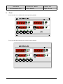
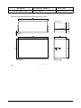
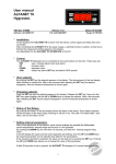
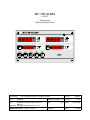
MC 785 KLIMA 0-100C User manual (Wall and Panel mount) Description : Doc.nr.: 080631 Number of pages: 16 Version: V1.0 File: Do080631 MC785 KLIMA 0_100 v10 EN.wpd Software: MC785KLIMA100 Version: V1.00 By: Date: VDH Products BV - Roden - Holland Signed: Type: MC 785 KLIMA 0-100C Thermo/Hygrostat MANUAL HN File: 14-03-2008 Doc'08 User manual MC 785 KLIMA 0-100C Document Nr. : 080631 Version : V1.0 Client : General Page : 2 of 16 Table of contents 1. Technical specifications . . . . . . . . . . . . . . . . . . . . . . . . . . . . . . . . . . . . . . . . . . . . . . . . . . . . . 3 2. Functional specifications . . . . . . . . . . . . . . . . . . . . . . . . . . . . . . . . . . . . . . . . . . . . . . . . . . . . 5 3. Control . . . . . . . . . . . . . . . . . . . . . . . . . . . . . . . . . . . . . . . . . . . . . . . . . . . . . . . . . . . . . . . . . 6 4. Programming internal settings . . . . . . . . . . . . . . . . . . . . . . . . . . . . . . . . . . . . . . . . . . . . . . . . 7 5. Operation relay outputs . . . . . . . . . . . . . . . . . . . . . . . . . . . . . . . . . . . . . . . . . . . . . . . . . . . . 10 6. Sensor calibration . . . . . . . . . . . . . . . . . . . . . . . . . . . . . . . . . . . . . . . . . . . . . . . . . . . . . . . . 11 7. Alarms . . . . . . . . . . . . . . . . . . . . . . . . . . . . . . . . . . . . . . . . . . . . . . . . . . . . . . . . . . . . . . . . . 11 8. Front . . . . . . . . . . . . . . . . . . . . . . . . . . . . . . . . . . . . . . . . . . . . . . . . . . . . . . . . . . . . . . . . . . 12 9. Connection diagrams . . . . . . . . . . . . . . . . . . . . . . . . . . . . . . . . . . . . . . . . . . . . . . . . . . . . . . 13 10. Dimensions . . . . . . . . . . . . . . . . . . . . . . . . . . . . . . . . . . . . . . . . . . . . . . . . . . . . . . . . . . . . . 15 The information contained in this document is assumed to be accurate. However, VDH Products BV does not accept any liability for eventual mistakes or errors, and retains the right to adapt or change this document without notice. User manual MC 785 KLIMA 0-100C 1. Document Nr. : 080631 Version : V1.0 Client : General Page : 3 of 16 Technical specifications General Type Wall mount version: Housing Material Dimensions Front Panel mount version: Housing Material Dimensions Panel cut Front Temperature range Rel. humidity range Power supply Power consumption Operating temperature Operating rel. humidity Accuracy Front Display LED's Keys : MC 785 KLIMA : Grey plastic : Polystyrol 454h KG 2 natur BASF : 213 x 180 x 85mm (whd) : Polycarbonate (IP-44) : Steel case for panel mount : Steel silver grey painted : 217 x 155 x 85mm (whd) : min. 208 x 146mm (wh) : Polycarbonate (IP-44) : 0/+100C per 0,1C : 0/+100% RH per 0,1% RH : 230 Vac; 50/60 Hz (-10/+5%). : 9 VA : -20/+50C : 10/+90 % RH not condensing : ± 0,5 % of the range : 4-digit digital 4-digit digital 4-digit digital 4-digit digital : COOL HEAT DEHUM HUM display for measured temperature display for temperature set point display for measured RH display for RH set point = LED Relay cooling active = LED Relay heating active = LED Relay dehumidifying active = LED Relay humidifying active = LED Alarm active (flashing) = LED Day mode active : ON/OFF SET PRG RESET ALARM = LED Night mode active = On/Off key controller = Set point push button = Up key = Down key = Program key = Alarm reset key User manual MC 785 KLIMA 0-100C Document Nr. : 080631 Version : V1.0 Client : General Page : 4 of 16 In- and Outputs Sensors Digital inputs Analog outputs Relay outputs : Temperature sensor (Pt-100, 3-wire to DIN/IEC 751) RH sensor (0/+1 Vdc = 0/+100% RH) : Day/night input (potential free input contact) External alarm input (potential free input contact) Spare input (potential free input contact) : 2x 0/+10Vdc, Rbmin 10Kohm, programmable. : RY1 Extra relay (C/NO/NC, 250Vac/10A not inductive) Options extra relay (adjustable with parameter 20); P20=0 Fail safe alarm (normal C-NO is closed and during alarm C-NC is closed) P20=1 Control alarm (normal C-NC is closed and during alarm C-NO is closed) P20=2 Function Cooling P20=3 Function Heating P20=4 Function Dehumidifying P20=5 Function Humidifying The following relays have a central common; RY2 Dehumidifying(NO, 250Vac/10A not inductive) RY3 Humidifying (NO, 250Vac/10A not inductive) RY4 Heating (NO, 250Vac/10A not inductive) RY5 Cooling (NO/NC, 250Vac/10A not inductive) User manual MC 785 KLIMA 0-100C 2. Document Nr. : 080631 Version : V1.0 Client : General Page : 5 of 16 Functional specifications The MC 785 KLIMA has the following control functions: cooling, heating, dehumidifying and humidifying. Further more the controller has an alarm relay, which is activated when the alarm levels are exceeded or a sensor is broken. The MC 785 KLIMA has two analog outputs with a range of 0/+10Vdc, these are controlled by three controllers. With Out-1 is controlled by Control-1 and Out-2 is controlled by the highest value of Control-2 and Control-3. The functions of these controllers are programmable as measuring signal, set point signal or a P(I) control for the cooling, heating, humidifying or dehumidifying. The controller has two digital input contacts. The first contact is used as day/night input and the second contact is used as external alarm. The selection of the above mentioned settings is done via the Internal Parameters. User manual MC 785 KLIMA 0-100C 3. Document Nr. : 080631 Version : V1.0 Client : General Page : 6 of 16 Control During normal operation the upper displays show the measured temperature and measured rel. humidity and the lower displays show the temperature set point and the RH set point. Changing the temperature set point. Push the SET key next to the temperature set point display. The set point starts flashing. The set point can be changed with the UP and DOWN key. By pushing the SET key once again, the set point shows continuously in the display. Is the MC 785 KLIMA in the day mode (DAY LED on) and should the night set point be watched or changed, push the UP or DOWN key and next on the SET key. The LED of the other mode flashes, the set point appears flashing in the display. Changing of the set point again with the UP or DOWN keys and acknowledged with the SET key. In the same way the day set point can be watched or changed if the MC 785 KLIMA is in the night mode. Changing of the RH set point. Push the SET key next to the RH set point display. The set point starts flashing and can be changed with the UP or DOWN keys. By pressing the SET key again the set point appears continuously in the display. If the instrument is in the day mode (DAG LED on) and the night set point needs to watched or changed, push the UP or DOWN key and next push the SET key. The LED of the other mode flashes, the set point appears flashing in the display. Changing of this set point again with the UP or DOWN keys and acknowledged with the SET key. In the same way the day set point can be watched or changed if the MC 785 KLIMA is in the night mode. Resetting the alarm. As soon as an alarm situation occurs and a failure message appears in the temperature display can, by pushing the RESET ALARM key, the alarm be reset. The error message remains in the display, till the cause of the failure is solved. Day/night input. If the day/night input is closed, the MC 785 KLIMA switches from day to night mode. The night LED light. If the input is opened, the controller switches back to the day mode. External alarm input. If the external alarm input is closed, an alarm message appears in the display. The alarm relais is activated. By pressing the ALARM RESET key, the alarm relay can be reset. The error message remains in the display, until the external alarm input is opened again. User manual MC 785 KLIMA 0-100C 4. Document Nr. : 080631 Version : V1.0 Client : General Page : 7 of 16 Programming internal settings By pressing the PRG and RESET ALARM key at the same time for more than 5 seconds, the Internal Parameter menu is entered. In the display appears a P with a number behind it. With the UP or DOWN key the required parameter is selected. If the required parameter is reached, can by pushing the PRG key, the value of the parameter be watched. By simultaneously pressing the PRG with the UP or DOWN key, the value can be adjusted. After releasing the keys, the parameter number appears again in the display. If during 30 seconds no key is touched, the display turn back to the normal operation mode. Parameter table. Number Description Range Unit Differential cooling Offset cooling Differential heating Offset heating Diff. dehumidifying Offset dehumidifying Diff. humidifying Offset humidifying 0.1..15 -15..+15 0.1..15 -15..+15 0.1..15 -15..+15 0.1..15 -15..+15 °C °C °C °C % RH % RH % RH % RH 0.5 0.0 0.5 0.0 1.0 0.0 1.0 0.0 P 10 P 11 Offset temp. sensor Offset RH sensor -10/+10 -15/+15 °C % RH 0.0 0.0 P 20 Function extra relay 0 = fail safe alarm 1 = control alarm 2 = cooling 3 = heating 4 = dehumidifying 5 = humidifying 6 = fail safe alarm not resettable 7 = control alarm not resettable 8 = extra relay; On when controller is on and off when controller is off Diff. extra relay Offset extra relay 0..8 - 0 0.1..15 -15..+15 - 0.5 0.0 P P P P P P P P 01 02 03 04 05 06 07 08 P 21 P 22 Default User manual MC 785 KLIMA 0-100C Number P 30 P 31 P 32 P 33 P 34 P 35 P 36 P 40 P P P P P 41 42 43 44 45 P 46 P 50 P P P P P 51 52 53 54 55 P 56 Document Nr. : 080631 Version : V1.0 Client : General Page : 8 of 16 Description Range Unit Minimum setting temperature set point Maximum setting temperature set point Read-out above -10°C per 1°C Read-out below -10°C per 1°C Minimum setting RH set point Maximum setting RH set point Read out per 1% RH 0..+100 °C 0.0 0..+100 °C +100.0 0 = No 1 = Yes 0 = No 1 = Yes 0..100 - 0 - 1 % RH 0 0..100 % RH 100 0 = No 1 = Yes - 0 Type temperature alarm 0 = No alarm 1 = Absolute alarm 2 = Relative to setp. Minimum alarm temp. Maximum alarm temp. Minimum alarm delay Maximum alarm delay Temperature control off at minimum alarm Temperature control off at maximum alarm 0..2 - 1 Type RH alarm 0 = No alarm 1 = Absolute 2 = Relative to setp. Minimum RH alarm Maximum RH alarm Minimum alarm delay Maximum alarm delay RH control off at minimum alarm RH control off at maximum alarm 0..+100 0..+100 0..99 0..99 0 = No 1 = Yes 0 = No 1 = Yes 0..2 -100..100 0..100 0..99 0..99 0 = No 1 = Yes 0 = No 1 = Yes °C °C Minutes Minutes - Default 0.0 +100.0 0 0 0 - 0 - 1 % RH % RH Minutes Minutes - 0.0 100.0 0 0 0 0 User manual MC 785 KLIMA 0-100C Number P 60 P P P P P 61 62 63 64 65 P 70 Document Nr. : 080631 Version : V1.0 Client : General Page : 9 of 16 Description Range Unit Function control-1=out1 0 = Measured temp. 1 = Measured RH 2 = Temperature setp. 3 = RH set point 4 = P(I) cooling 5 = P(I) heating 6 = P(I) dehumidifying 7 = P(I) humidifying 0 V output at 10 V output at Proportional range Offset prop. range Interval value (999 give only P) 0..7 - -100..+100 -100..+100 0.1..15 -15..+15 1..999 Minutes Function control-2>out2 0 = Measured temp. 1 = Measured RH 2 = Temperature setp. 3 = RH set point 4 = P(I) cooling 5 = P(I) heating 6 = P(I) dehumidifying 7 = P(I) humidifying 0 V output at 10 V output at Proportional range Offset prop. range Interval value (999 gives only P) 0..7 - Default 0 -0.0 +100.0 1.0 0.0 999 0 0.0 +100.0 1.0 0.0 999 -100..+100 -100..+100 0.1..15 -15..+15 1..999 Minutes Function control-3>out2 0 = 0Vdc (not active) 1 = P(I) cooling 2 = P(I) heating 3 = P(I) dehumidifying 4 = P(I) humidifying Proportional range Offset prop. range Interval value (999 gives only P) 0..4 - 0 0.1..15 -15..+15 1..999 Minutes 1.0 0.0 999 Analog out-1 as Pulse/Pause control Pulse/Pause cycle-time1 0 = No 1 = Yes 5..240 - 0 Sec. 20 Analog out-2 as Pulse/Pause control Pulse/Pause cycle time2 0 = No 1 = Yes 5..240 - 0 Sec. 20 P 100 Complete control off at external alarm 0 = No 1 = Yes - 0 P 105 P 106 P 107 Software version nr. Serial number Production date - Year/w - P P P P P 71 72 73 74 75 P 80 P 83 P 84 P 85 P 90 P 91 P 95 P 96 User manual MC 785 KLIMA 0-100C 5. Document Nr. : 080631 Version : V1.0 Client : General Page : 10 of 16 Operation relay outputs Operation of the cooling and heating. The cooling (RY5) switches if the temperature is higher than set point + offset cooling + differential cooling and switches off if the temperature is lower than set point + offset cooling. The heating (RY4) switches if the temperature is lower than set point + offset heating - differential heating and switches off id the temperature is higher than set point + offset heating. Operation of the humidifying and dehumidifying functions The dehumidifying Relay (RY2) switches on if the RH is higher than set point + offset dehumidify + differential dehumidify and switches off if the RH is lower than set point + offset dehumidify. The humidifying Relay (RY3) switches on if the RH is lower than the set point + offset humidify differential humidify and switches off if the RH is lower than set point + offset humidify. User manual MC 785 KLIMA 0-100C 6. Document Nr. : 080631 Version : V1.0 Client : General Page : 11 of 16 Sensor calibration With parameters P10 and P11 can the temperature and RH sensor be calibrated. Indicates the temperature sensor e.g. 0,2C too much, the offset (P 10) should be set at -0,2C. 7. Alarms If the extra relay is set as watch alarm (parameter P20=0), in normal mode the relay is on and drops during alarm. In this mode also an alarm is given if the power supply is lost. If the extra relay is programmed as control alarm (P20=1), in normal mode the relay is off and is switches on during alarm. During alarm the alarm LED on the front flashes. Depending on the setting of the Internal Parameters the control will stop or continue. An alarm can be caused by: Temperature alarm : RH alarm : External alarm : Sensor failure : tLO tHI rLO rHI F1 E1 E2 = Minimum temperature alarm = Maximum temperature alarm = Minimum RH alarm = Maximum RH alarm = External alarm = Temperature sensor broken = RH sensor broken The temperature alarm messages tLO, tHI, E1 and external alarm message F1 are displayed in the temperature display (left top). The RH alarm messages rLO, rHI and E2 are shown in the RH-display (right top). By pressing the RESET ALARM key the extra relay will, if configured as alarm relay, be reset. The error message remains during the failure in the display. Also the alarm LED will continue to flash. User manual MC 785 KLIMA 0-100C 8. Document Nr. : 080631 Version : V1.0 Client : General Page : 12 of 16 Front Front view MC 785 - KLIMA wall-mounting drawing 960581 Front view MC785-KLIMA panel mounting drawing 961365 User manual MC 785 KLIMA 0-100C 9. Document Nr. : 080631 Version : V1.0 Client : General Page : 13 of 16 Connection diagrams Connections MC 785 - KLIMA wall-mounting drawing 021743 Several RH-sensors can be connected: RH95-2, LC95-2 or RH970 humidity sensors (Also for panel mounting) User manual MC 785 KLIMA 0-100C Document Nr. : 080631 Version : V1.0 Client : General Page : 14 of 16 Connections MC785-KLIMA panel-mounting drawing 021742 User manual MC 785 KLIMA 0-100C Document Nr. : 080631 Version : V1.0 Client : General Page : 15 of 16 10. Dimensions Dimensions MC785-KLIMA wall-mounting drawing 940024 User manual MC 785 KLIMA 0-100C Document Nr. : 080631 Version : V1.0 Client : General Page : 16 of 16 Dimensions MC785-KLIMA panel-mounting drawing 961271 @ -.-.-.-.-.-.-.-.-.-