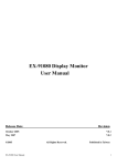
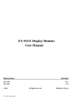
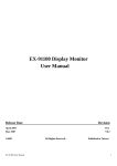
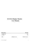
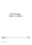
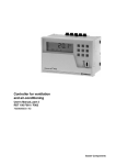
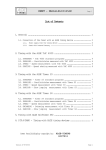
1
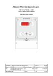
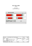
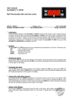
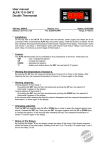
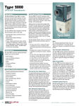
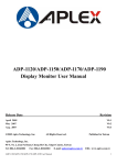
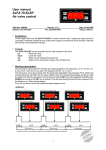
MC 785D-6p OF wall or panel mount User manual Describtion : MC 785D-6P OF Thermostat with max. 6 temp.sensors Doc.nr.: 061775 Type: MANUAL Number of pages: 12 Version: V1.0 File: Do061775 MC785D-6P F v10 EN.wpd MC785D-6P Version: V1.00 By: Date: Software: VDH Products BV - Roden - Holland Signed: BJB File: 22-06-2006 Doc'06 User manual MC 785D-6P OF Document nr. : 061775 Version : V1.0 Client: General Page : 2 of 12 Table of Contents 1. Technical specifications . . . . . . . . . . . . . . . . . . . . . . . . . . . . . . . . . . . . . . . . . . . . . . . . . . . . . . . . . . 3 2. Functional specifications . . . . . . . . . . . . . . . . . . . . . . . . . . . . . . . . . . . . . . . . . . . . . . . . . . . . . . . . . 4 3. Operation . . . . . . . . . . . . . . . . . . . . . . . . . . . . . . . . . . . . . . . . . . . . . . . . . . . . . . . . . . . . . . . . . . . . . 5 4. Programming Internal Settings . . . . . . . . . . . . . . . . . . . . . . . . . . . . . . . . . . . . . . . . . . . . . . . . . . . . . 6 5. Operation of relay outputs . . . . . . . . . . . . . . . . . . . . . . . . . . . . . . . . . . . . . . . . . . . . . . . . . . . . . . . . 7 6. Sensor calibration . . . . . . . . . . . . . . . . . . . . . . . . . . . . . . . . . . . . . . . . . . . . . . . . . . . . . . . . . . . . . . . 8 7. Alarms . . . . . . . . . . . . . . . . . . . . . . . . . . . . . . . . . . . . . . . . . . . . . . . . . . . . . . . . . . . . . . . . . . . . . . . 8 8. Front views . . . . . . . . . . . . . . . . . . . . . . . . . . . . . . . . . . . . . . . . . . . . . . . . . . . . . . . . . . . . . . . . . . . . 9 9. Connection diagram . . . . . . . . . . . . . . . . . . . . . . . . . . . . . . . . . . . . . . . . . . . . . . . . . . . . . . . . . . . . 10 10. Dimensions . . . . . . . . . . . . . . . . . . . . . . . . . . . . . . . . . . . . . . . . . . . . . . . . . . . . . . . . . . . . . . . . . . 12 The information contained in this document is assumed to be accurate. However VDH Products BV accepts no liability for eventual mistakes or errors and has the right to change this document without notice. User manual MC 785D-6P OF Document nr. : 061775 Version : V1.0 Client: General Page : 3 of 12 1. Technical specifications General Type Wall mount version: Housing Material Dimensions Front Panel mount version: Housing Material Dimensions Panel cut Front Range Power supply Power consumption Operating temperature Store temperature Operating RH Accuracy : MC 785D-6P OF : Grey plastic : Polystyrol 454h KG 2 natur BASF : 213 x 180 x 85mm (whd) : Polycarbonate (IP-44) : Steel panel mount housing : Steel painted silver grey : 217 x 155 x 85mm (whd) : min. 208 x 146mm (wh) : Polycarbonate (IP-44) : -40/+120°F per 0,1°F : 120 Vac; 50/60 Hz (-10/+5%) (or other see sticker) : 9 VA : -5/+120°F : -5/+140°F : 10/+90 % RH not condensing : ± 0,5 % of the range Front Display LED's Keys : 4-digit digital display for temperature indication : 4-digit digital display for setpoint indication : = Led Relay cooling active = Led Relay heating active = Led Alarm active S1 = Temperature sensor 1 read-out S2 = Temperature sensor 2 read-out S3 = Temperature sensor 3 read-out S4 = Temperature sensor 4 read-out S5 = Temperature sensor 5 read-out S6 = Temperature sensor 6 read-out : ON/OFF PRG SENS SETP. = On/off key controller = Program key = Up key = Down key = Sensor read-out key = Setpoint key User manual MC 785D-6P OF Document nr. : 061775 Version : V1.0 Client: General Page : 4 of 12 In- and Outputs Sensors Relays Others : Sensor 1 (Pt-100, 3-wire to DIN/IEC 751) Sensor 2 (Pt-100, 3-wire to DIN/IEC 751) Sensor 3 (Pt-100, 3-wire to DIN/IEC 751) Sensor 4 (Pt-100, 3-wire to DIN/IEC 751) Sensor 5 (Pt-100, 3-wire to DIN/IEC 751) Sensor 6 (Pt-100, 3-wire to DIN/IEC 751) : RY1 Alarm (C/NO/NC, 250Vac/10A not inductive) Normal C-NO is closed, at alarm C-NC is closed. Following relays have one central common; RY2 Function-1 (NO, 250Vac/10A not inductive) RY3 Function-2 (NO, 250Vac/10A not inductive) : Network connection (option) 2. Functional specifications The MC 785D-6P is a thermostat, to which a maximum of six temperature sensors can be connected. The temperature is controlled on the average of the active sensors. The thermostat can be programmed with the control functions; one stage cooling (RY2) or two stage cooling (RY2 and RY3) or one stage heating (RY2) or two stage heating (RY2 and RY3) or cooling (RY2) and heating (RY3). The MC 785D-6P has an alarm relay, which switches on if the temperature of one of the sensors drops below or above the preset alarm levels. The selection of the above mentioned settings is done thru the Internal Parameters. User manual MC 785D-6P OF Document nr. : 061775 Version : V1.0 Client: General Page : 5 of 12 3. Operation Normally the temperature display shows the average temperature of the active control sensors and the setpoint display the current setpoint. De LED's S1 to S6 indicate which temperature sensors are active and the status LED's show if the thermostat is cooling, heating or if there is an alarm. Read-out of the sensors. Press the SENS key. The LED S1 lights and in display shows the temperature of sensor 1. By pressing the SENS key again, the other sensors can shown. When all sensors are displayed, the average temperature appears again in the display. Changing the setpoint. Push simultaneously on the SETP. and the UP or DOWN key to change the setpoint. Switching sensors on and off. Push the SENS and PRG key simultaneously. The upper display shows the text S1 and the lower display ON if the sensor is switched on or OFF if the sensor is switched off. By pressing the SETP. key, the sensor can be switched ON or OFF. If the sensor is switched off in this way, the sensor can still be read out but it doesn’t count in the regulation. With the UP and DOWN keys the other sensors can be watched and switched ON or OFF as above mentioned. Reset the alarm. As soon as an alarm situation occurs and an error message in the display appears, can by pressing the PRG key, the alarm be reset. The error message remains in the display, until the cause of the error is solved. User manual MC 785D-6P OF Document nr. : 061775 Version : V1.0 Client: General Page : 6 of 12 4. Programming Internal Settings By pressing the PRG key for more than 5 seconds, the Interne Parameters are shown. In the upper display appears a P with a number. With the UP or DOWN key the required parameter can be selected. The value of the parameter is shown in the lower display. By pushing the SETP. and the UP or DOWN key simultaneously, the value of the parameter can be changed. If during 30 seconds no key is touched or if the PRG key is pressed, the display returns to the normal operation mode. Parameter table. Number Description Range Unit Default P 01 0..4 - 4 P 02 P 03 P 04 P 05 Function thermostat 0 = 1x cooling 1 = 2x cooling 2 = 1x heating 3 = 2x heating 4 = cooling/heating Differential function 1 Offset function 1 Differential function 2 Offset function 2 0.0..+30 -30..+30 0.0..+30 -30..+30 F F F F 1.0 0.0 1.0 0.0 P 11 P 12 P 13 P 14 P 15 P 16 P 21 P 22 P 23 P 24 P 25 P 26 Sensor 1 present Sensor 2 present Sensor 3 present Sensor 4 present Sensor 5 present Sensor 6 present Offset Sensor 1 Offset Sensor 2 Offset Sensor 3 Offset Sensor 4 Offset Sensor 5 Offset Sensor 6 0..1 0..1 0..1 0..1 0..1 0..1 -20..+20 -20..+20 -20..+20 -20..+20 -20..+20 -20..+20 F F F F F F 1 1 1 1 1 1 0.0 0.0 0.0 0.0 0.0 0.0 P 30 P 31 P 32 P 33 P 34 Minimum alarm temperature Maximum alarm temperature Min. alarm delay Max. alarm delay Alarm relay off after reset alarm -40..+120 -40..+120 0..99 0..99 0 = No 1 = Yes F F Minutes Minutes - -40.0 +120.0 30 30 0 P 40 P 41 P 42 Minimum setpoint Maximum setpoint Read-out above -10°F per degree Read-out below -10°F per degree -40..+120 -40..+120 0 = No 1 = Yes 0 = No 1 = Yes F F - -40.0 +120.0 0 - 1 Network number Software version number Serial number Production date 1-99 - year/wk 1 - P 43 P 90 P 97 P 98 P 99 User manual MC 785D-6P OF Document nr. : 061775 Version : V1.0 Client: General Page : 7 of 12 5. Operation of relay outputs Operation of the cooling and heating. 2x ccoling: Cooling 1 (RY2) switches on if the temperature is higher then setpoint + offset_1 + differentie_1 en switches off if the temperature is lower then setpoint + offset_1. Cooling 2 (RY3) switches on if the temperature is higher then setpoint + offset_2 + differentie_2 and switches off if the temperature is lower then setpoint + offset_2. 2x heating: Heating 1 (RY2) switches on if the temperature is lower then setpoint + offset_1 differentie_1 and switches off if the temperature is lower then setpoint + offset_1. Heating 2 (RY3) switches on if the temperature is lower then setpoint + offset_2 differentie_2 and switches off if the temperature is lower then setpoint + offset_2. Cooling/heating: Cooling (RY2) switches on if the temperature is higher then setpoint + offset_1 + differentie_1 and switches off if the temperature is lower then setpoint + offset_1. Heating (RY3) switches on if the temperature is lower then setpoint + offset_2 differentie_2 and switches off if the temperature is higher then setpoint + offset_2. Function Diagram Cool/Heat User manual MC 785D-6P OF Document nr. : 061775 Version : V1.0 Client: General Page : 8 of 12 6. Sensor calibration With the parameters P21 to P26 the sensors can be calibrated. Indicates e.g. a sensor 0.2°F too much, that offset-parameter must be set 0.2°F lower. 7. Alarms If there is no alarm, the alarm relay is on and during alarm the alarm relay drops. Now also an alarm is given during a power failure. During alarm the alarm LED on the front flashes. An alarm can be cause by: - No control sensor present (F1) - Sensor broken (E1, E2, E3, E4, E5 or E6). - A sensor gives a minimum or maximum alarm (LO or HI). By pressing the PRG key during alarm, the alarm relay will be reset. The alarm message remains in the display during the failure. Also the alarm LED will continue flashing. Temperature alarm: LO = Minimum alarm HI = Maximum alarm No control sensor: F1 = No control sensor present Sensor failure: E1 = Sensor 1 broken E2 = Sensor 2 broken E3 = Sensor 3 broken E4 = Sensor 4 broken E5 = Sensor 5 broken E6 = Sensor 6 broken User manual MC 785D-6P OF 8. Front views Drawing 061779: Wall mounting Drawing 061776: Panel mounting Document nr. : 061775 Version : V1.0 Client: General Page : 9 of 12 User manual MC 785D-6P OF 9. Connection diagram Drawing 061675: Wall mounting Document nr. : 061775 Version : V1.0 Client: General Page : 10 of 12 User manual MC 785D-6P OF Drawing 061778: Panel mounting Document nr. : 061775 Version : V1.0 Client: General Page : 11 of 12 User manual MC 785D-6P OF Document nr. : 061775 Version : V1.0 Client: General Page : 12 of 12 10. Dimensions MC785-serie wall mounting drawing 940024 @ MC785-serie panelmounting drawing 961271