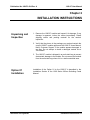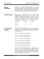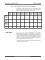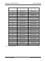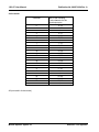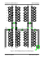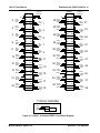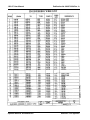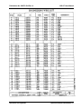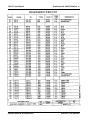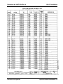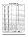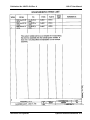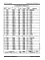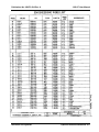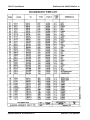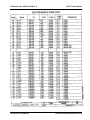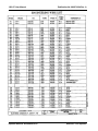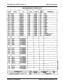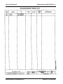
1
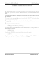
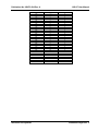
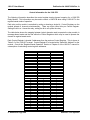
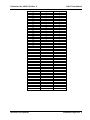
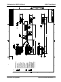
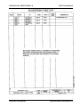
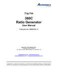
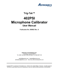
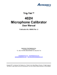
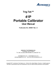
RACAL INSTRUMENTS™
1260-37
SWITCH MODULE
Publication No. 980673-024 Rev. A
Astronics Test Systems Inc.
4 Goodyear, Irvine, CA 92618
Tel: (800) 722-2528, (949) 859-8999; Fax: (949) 859-7139
[email protected] [email protected]
[email protected] http://www.astronicstestsystems.com
Copyright 1994 by Astronics Test Systems Inc. Printed in the United States of America. All rights reserved.
This book or parts thereof may not be reproduced in any form without written permission of the publisher.
THANK YOU FOR PURCHASING THIS
ASTRONICS TEST SYSTEMS PRODUCT
For this product, or any other Astronics Test Systems product that incorporates software drivers,
you may access our web site to verify and/or download the latest driver versions. The web address
for driver downloads is:
http://www.astronicstestsystems.com/support/downloads
If you have any questions about software driver downloads or our privacy policy, please contact us
at:
[email protected]
WARRANTY STATEMENT
All Astronics Test Systems products are designed to exacting standards and manufactured in full
compliance to our AS9100 Quality Management System processes.
This warranty does not apply to defects resulting from any modification(s) of any product or part
without Astronics Test Systems express written consent, or misuse of any product or part. The
warranty also does not apply to fuses, software, non-rechargeable batteries, damage from battery
leakage, or problems arising from normal wear, such as mechanical relay life, or failure to follow
instructions.
This warranty is in lieu of all other warranties, expressed or implied, including any implied warranty
of merchantability or fitness for a particular use. The remedies provided herein are buyer’s sole
and exclusive remedies.
For the specific terms of your standard warranty, contact Customer Support. Please have the
following information available to facilitate service.
1. Product serial number
2. Product model number
3. Your company and contact information
You may contact Customer Support by:
E-Mail:
[email protected]
Telephone:
+1 800 722 3262
(USA)
Fax:
+1 949 859 7139
(USA)
RETURN OF PRODUCT
Authorization is required from Astronics Test Systems before you send us your product or sub-assembly for
service or calibration. Call or contact Customer Support at 1-800-722-3262 or 1-949-859-8999 or via fax at 1949-859-7139. We can also be reached at: [email protected].
If the original packing material is unavailable, ship the product or sub-assembly in an ESD shielding bag and
use appropriate packing materials to surround and protect the product.
PROPRIETARY NOTICE
This document and the technical data herein disclosed, are proprietary to Astronics Test Systems, and shall
not, without express written permission of Astronics Test Systems, be used in whole or in part to solicit
quotations from a competitive source or used for manufacture by anyone other than Astronics Test Systems.
The information herein has been developed at private expense, and may only be used for operation and
maintenance reference purposes or for purposes of engineering evaluation and incorporation into technical
specifications and other documents which specify procurement of products from Astronics Test Systems.
TRADEMARKS AND SERVICE MARKS
All trademarks and service marks used in this document are the property of their respective owners.
•
Racal Instruments, Talon Instruments, Trig-Tek, ActivATE, Adapt-A-Switch, N-GEN, and PAWS are
trademarks of Astronics Test Systems in the United States.
DISCLAIMER
Buyer acknowledges and agrees that it is responsible for the operation of the goods purchased and should
ensure that they are used properly and in accordance with this document and any other instructions provided
by Seller. Astronics Test Systems products are not specifically designed, manufactured or intended to be
used as parts, assemblies or components in planning, construction, maintenance or operation of a nuclear
facility, or in life support or safety critical applications in which the failure of the Astronics Test Systems
product could create a situation where personal injury or death could occur. Should Buyer purchase Astronics
Test Systems product for such unintended application, Buyer shall indemnify and hold Astronics Test
Systems, its officers, employees, subsidiaries, affiliates and distributors harmless against all claims arising out
of a claim for personal injury or death associated with such unintended use.
FOR YOUR SAFETY
Before undertaking any troubleshooting, maintenance or exploratory procedure, read carefully the
WARNINGS and CAUTION notices.
This equipment contains voltage hazardous to
human life and safety, and is capable of inflicting
personal injury.
If this instrument is to be powered from the AC line (mains) through an autotransformer,
ensure the common connector is connected to the neutral (earth pole) of the power
supply.
Before operating the unit, ensure the conductor (green wire) is connected to the ground
(earth) conductor of the power outlet. Do not use a two-conductor extension cord or a
three-prong/two-prong adapter. This will defeat the protective feature of the third
conductor in the power cord.
Maintenance and calibration procedures sometimes call for operation of the unit with
power applied and protective covers removed. Read the procedures and heed warnings
to avoid “live” circuit points.
Before operating this instrument:
1. Ensure the proper fuse is in place for the power source to operate.
2. Ensure all other devices connected to or in proximity to this instrument are properly grounded or
connected to the protective third-wire earth ground.
If the instrument:
-
fails to operate satisfactorily
shows visible damage
has been stored under unfavorable conditions
has sustained stress
Do not operate until performance is checked by qualified personnel.
This page was left intentionally blank.
.
Publication No. 980673-024 Rev. A
1260-37 User Manual
NOTE FOR SYSTEMS WITH 1260-OPT 01T
The “Module-Specific Syntax” section of this manual shows the command syntax for the 1260-01S
Smart Card. If you are using the newer 1260-01T Smart Card, the commands will NOT work as
shown.
Consult the 1260-01T Manual for a description of the commands which may be used with the 126001T Smart Card.
The channel numbers described in this manual are valid for the 1260-01T. The channel numbers
continue to be used for the 1260-01T.
The syntax of the commands which use channel numbers has changed for those cards controlled
by the 1260-01T.
The new syntax used to close a channel is:
CLOSE (@ <module address> ( <channel> ) )
For example, with for a relay module whose <module address> is set to 7, closing <channel> 0 is
performed with the command:
CLOSE (@ 7 (0))
Using the older 1260-01S, the command would be (as shown in this manual):
CLOSE 7.0
Many other command syntax differences exist. Please consult chapter 2 of the 1260-01T manual
for a description of the commands which are available for the 1260-01T.
Astronics Test Systems
Addendum Page 6/98 1
1260-37 User Manual
Publication No. 980673-024 Rev. A
Control Information for the 1260-37A
The following information describes the control-register-to-relay-channel mapping for a 1260-37A
Relay Module. This information may be used to control a 1260-37A when using a 1260-01T in the
register-based mode of operation.
The table below shows the mapping between logical channels used to operate the relay module in
message-based mode and the bits within the Control Registers which may be used to operate the
channel in register-based mode.
Each Control Register is located 2 addresses from the previous Control Register. This is shown in
Table 2-2 of the 1260-01T manual. Control Register 0 is located at the “Base A24 Address” for the
module. Consult the “Register-Based Operation” Section of Chapter 2 of the 1260-01T manual for
a description of calculating control register addresses.
Each channel between 0 and 23 (inclusive) is operated by setting or clearing two bits in parallel.
One bit in each of two different Control Registers must be set to operate these channels as a 4wire MUX.
Channels 100 through 139 are each operated by a single bit of a single Control Register.
Channel
0
1
2
3
4
5
6
7
8
9
10
11
12
13
14
15
16
17
18
19
20
21
22
23
100
101
102
103
104
105
106
107
108
109
2 Addendum Page 6/98
Control Register
0 and 3
0 and 3
0 and 3
0 and 3
0 and 3
0 and 3
0 and 3
0 and 3
1 and 4
1 and 4
1 and 4
1 and 4
1 and 4
1 and 4
1 and 4
1 and 4
2 and 5
2 and 5
2 and 5
2 and 5
2 and 5
2 and 5
2 and 5
2 and 5
6
6
6
6
6
6
6
6
7
7
Control Bit
0
1
2
3
4
5
6
7
0
1
2
3
4
5
6
7
0
1
2
3
4
5
6
7
0
1
2
3
4
5
6
7
0
1
Astronics Test Systems
Publication No. 980673-024 Rev. A
Channel
110
111
112
113
114
115
116
117
118
119
120
121
122
123
124
125
126
127
128
129
130
131
132
133
134
135
136
137
138
139
Astronics Test Systems
1260-37 User Manual
Control Register
7
7
7
7
7
7
8
8
8
8
8
8
8
8
9
9
9
9
9
9
9
9
10
10
10
10
10
10
10
10
Control Bit
2
3
4
5
6
7
0
1
2
3
4
5
6
7
0
1
2
3
4
5
6
7
0
1
2
3
4
5
6
7
Addendum Page 6/98 3
1260-37 User Manual
Publication No. 980673-024 Rev. A
Control Information for the 1260-37B
The following information describes the control-register-to-relay-channel mapping for a 1260-37B
Relay Module. This information may be used to control a 1260-37B when using a 1260-01T in the
register-based mode of operation.
Each relay on this module is controlled by setting or clearing a single bit. Control Registers on the
module operate 8 channels simultaneously. There are eight control bits per Control Register.
Setting the bit to a 1 closes the relay; setting the bit to a 0 opens the relay.
The table below shows the mapping between logical channels used to operate the relay module in
message-based mode and the bits within the Control Registers which may be used to operate the
channel in register-based mode.
Each Control Register is located 2 addresses from the previous Control Register. This is shown in
Table 2-2 of the 1260-01T manual. Control Register 0 is located at the “Base A24 Address” for the
module. Consult the “Register-Based Operation” Section of Chapter 2 of the 1260-01T manual for
a description of calculating control register addresses.
Channel
0
1
2
3
4
5
6
7
8
9
10
11
12
13
14
15
16
17
18
19
20
21
22
23
24
25
26
27
28
29
30
31
32
33
34
35
36
37
4 Addendum Page 6/98
Control Register
0
0
0
0
0
0
0
0
1
1
1
1
1
1
1
1
2
2
2
2
2
2
2
2
3
3
3
3
3
3
3
3
4
4
4
4
4
4
Control Bit
0
1
2
3
4
5
6
7
0
1
2
3
4
5
6
7
0
1
2
3
4
5
6
7
0
1
2
3
4
5
6
7
0
1
2
3
4
5
Astronics Test Systems
Publication No. 980673-024 Rev. A
Channel
38
39
40
41
42
43
44
45
46
47
48
100
101
102
103
104
105
106
107
108
109
110
111
112
113
114
115
116
117
118
119
120
121
122
123
124
125
126
127
128
129
130
131
132
133
134
135
136
137
138
139
Astronics Test Systems
1260-37 User Manual
Control Register
4
4
5
5
5
5
5
5
5
5
12
6
6
6
6
6
6
6
6
7
7
7
7
7
7
7
7
8
8
8
8
8
8
8
8
9
9
9
9
9
9
9
9
10
10
10
10
10
10
10
10
Control Bit
6
7
0
1
2
3
4
5
6
7
0
0
1
2
3
4
5
6
7
0
1
2
3
4
5
6
7
0
1
2
3
4
5
6
7
0
1
2
3
4
5
6
7
0
1
2
3
4
5
6
7
Addendum Page 6/98 5
1260-37 User Manual
Publication No. 980673-024 Rev. A
This page was left intentionally blank.
6 Addendum Page 6/98
Astronics Test Systems
Publication No. 980673-024 Rev. A
1260-37 User Manual
Table of Contents
Chapter 1 ............................................................................................................................ 1-1
MODULE SPECIFICATION .......................................................................................................... 1-1
1260-37 Module Specification ................................................................................................... 1-1
Specifications......................................................................................................................... 1-2
Ordering Information ................................................................................................................. 1-4
Safety ........................................................................................................................................ 1-4
Chapter 2 ............................................................................................................................ 2-1
INSTALLATION INSTRUCTIONS ................................................................................................. 2-1
Unpacking and Inspection ......................................................................................................... 2-1
Option 01 Installation ................................................................................................................. 2-1
Module Installation..................................................................................................................... 2-2
1260-37 ID Byte ........................................................................................................................ 2-2
Configuration Jumpers .............................................................................................................. 2-2
Analog Bus ................................................................................................................................ 2-3
Astronics Test Systems
i
1260-37 User Manual
Publication No. 980673-024 Rev. A
Chapter 3 ............................................................................................................................ 3-1
MODULE SPECIFIC SYNTAX ...................................................................................................... 3-1
1260-37 Module Specific Syntax ............................................................................................... 3-1
Syntax ................................................................................................................................... 3-1
CLOSE and OPEN Command ........................................................................................... 3-2
PSETUP Command ........................................................................................................... 3-2
PDATAOUT Command ...................................................................................................... 3-3
Operation In Single-Wire Mode ............................................................................................. 3-3
Chapter 4 ............................................................................................................................ 4-1
OPTIONAL HARNESS ASSEMBLIES .......................................................................................... 4-1
ii
Astronics Test Systems
Publication No. 980673-024 Rev. A
1260-37 User Manual
List of Figures
Figure 1-1, 1260-37 Switching Card.............................................................................................. 1-1
Figure 3-1, 1260-37 Multiplexer/Scanner Circuit Block Diagram ................................................... 3-7
Figure 3-2, 1260-37 40-Channel SPDT Circuit Block Diagram ...................................................... 3-8
Figure 3-3, 1260-37 Pin Connections ............................................................................................ 3-9
Astronics Test Systems
iii
1260-37 User Manual
Publication No. 980673-024 Rev. A
List of Tables
Table 2-1, 1260-37 Multiplexer/Scanner Circuit Jumper Installation ............................................. 2-3
Table 3-1, 1260-37 Multiplexer/Scanner Circuit Channel Closure ................................................. 3-4
iv
Astronics Test Systems
Publication No. 980673-024 Rev. A
1260-37 User Manual
DOCUMENT CHANGE HISTORY
Revision
A
Astronics Test Systems
Date
Description of Change
01/11/10
Revised per EO 30004.
Revised format to current standards. Company name
revised throughout manual. Manual now revision letter
controlled. Added Document Change History Page v.
Back of cover sheet. Revised Warranty Statement,
Return of Product, Proprietary Notice and Disclaimer
to current standards.
(Chap2-1) Unpacking and
inspection. Revise to current standards. Removed
Reshipment Instructions in (Chap. 2-1) and removed
(Chap 5). Information. Now appears in first 2 sheets
behind cover sheet. Updated table of contents to reflect
changes made. .
Added company name to footer opposite page no’s i
thru vi.
v
1260-37 User Manual
Publication No. 980673-024 Rev. A
This page was left intentionally blank.
vi
Astronics Test Systems
Publication No. 980673-024 Rev. A
1260-37 User Manual
Chapter 1
MODULE SPECIFICATION
1260-37 Module
Specification
The 1260-37 switch module consists of two switch circuits; a 1 x
48 Signal Multiplexer/Scanner and a 40-Channel SPDT Switch.
The Signal Multiplexer circuit switches two lines per channel, and
has the capability of being configured as one 1 x 48 multiplexer,
two 1 x 24 multiplexers, four 1 x 12 multiplexers, or eight 1 x 6
multiplexers. The signal mulitplexer configuration is user
selectable, but is supplied from the factory in the one 1 x 48 twowire mode. In addition, the multiplexer may be configured as a
one-wire 1 x 96 multiplexer. A block diagram of this circuit is
shown in Figure 3-1. The 40 channel SPDT switch circuit provides
40 independent channels of switching. Each channel features one
common line that connects to either a normally open or normally
closed position. A block diagram of this circuit is shown in Figure
3-2.
Figure 1-1, 1260-37 Switching Card
Astronics Test Systems
Module Specification 1-1
1260-37 User Manual
Specifications
Publication No. 980673-024 Rev. A
1 x 48 Signal Multiplexer/Scanner
Switch Configurations
Four-wire mode (any
configuration)
Two-wire mode (any
configuration)
Maximum Switchable Voltage
250 VDC, 250 VAC RMS
(Terminal-Terminal or Terminal-Chassis)
Maximum Switchable Current 1A, DC or AC RMS
(Per Channel)
Maximum Switchable Power
(Per Channel)
30 WDC, 62.5 VA AC
Path Resistance
<0.30Ω (1 x 6 configuration)
<0.50Ω (1 x 48 configuration)
Isolation Hi-Lo
> 7.5 x 10⁸ Ω
Capacitance
Open Channel
Channel-Chassis
HI-LO
Bandwidth (50Ω Termination)
Module Specification 1-2
< 50pf (1x 6 configuration)
< 50pf (1x 6 configuration)
<300pf (1x 48 configuration)
< 80pf (1x 6 configuration)
<400pf (1x 48 configuration)
>35 MHz (1 x 6 configuration)
>15 MHz (1 x 48 configuration)
Insertion Loss (50Ω Termination)
1 x 6 Configuration
<.1 dB to 100 kHz
<.5 dB to 1 MHz
<1 dB to 10 MHz
Insertion Loss (50Ω Termination)
1 x 48 Configuration
<.1 dB to 100kHz
<1.0 dB to 1 MHz
<1.0 dB to 10 MHz
Crosstalk
(50Ω Termination)
<-40 dB to 100 kHz
<-35 dB to 1 MHz
<-15 dB to 10MHz
Isolation
>45 dB to 100kHz
>40 dB to 1 MHz
>33 dB to 10MHz
Switching Time
2 mS
Astronics Test Systems
Publication No. 980673-024 Rev. A
1260-37 User Manual
40 Channel SPDT Switch
Maximum Switchable Voltage
250 VDC, 250 VAC RMS
(Terminal-Terminal or Terminal Chassis)
Maximum Switchable Current 1 A,DC or AC RMS
(Per Channel)
Maximum Switchable Power
(Per Channel)
30 WDC, 62.5 VA AC
Path Resistance
<0.5 Ω
DC Isolation COM-NO
>2x 10⁹ Ω
Bandwidth
(50Ω termination)
>35 MHz
Insertion Loss
(50Ω termination)
<.1 dB to 100kHz
<.5 dB to 1 MHz
<1 dB to 10 MHz (typical)
Crosstalk
(50Ω termination)
<-40 dB to 100 kHz
<-35 dB to 1 MHz
<-20 dB to 10 MHz
Isolation
(50Ω termination)
> 40 dB to 100 kHz
> 35 dB to 1 MHz
> 28 dB to 10 MHz
Switching Time
2 mS
Cooling Requirements
Airflow
4 liters/sec
Backpressure
0.5mm of Hg
Power Requirements (Imp)
+5V without Option 0l =
400mA
+5V with Option 0l = 2.5A
+24V = l0mA per relay
Weight
1.26kg (2.771bs) without
Option 0l
1.41kg (3.lllbs) with Option 0l
User Connector
64-Pin (2 Row)
IDC Quick Disconnect*
Minimum Firmware Revision
Astronics Test Systems
Module Specification 1-3
1260-37 User Manual
Publication No. 980673-024 Rev. A
Option 0l
23.1
*A crimp connector kit is also available for this module (P/N
404975-003). A strain relief option can be ordered separately for
this crimp connector kit.
Ordering
Information
Safety
Module Specification 1-4
Model Number
Description
Part Number
1260-37
1 x 48 Signal Multiplexer/
Scanner, 40-Channel,
SPDT Switch
407353
Refer to the "FOR YOUR SAFETY" page preceding the Table of
Contents. Follow all NOTES, CAUTIONS and WARNINGS to
ensure personal safety and prevent damage to the instrument.
Astronics Test Systems
Publication No. 980673-024 Rev. A
1260-37 User Manual
Chapter 2
INSTALLATION INSTRUCTIONS
Unpacking and
Inspection
1. Remove the 1260-37 module and inspect it for damage. If any
damage is apparent, inform the carrier immediately. Retain
shipping carton and packing material for the carrier’s
inspection.
2. Verify that the pieces in the package you received contain the
correct 1260-37 module option and the 1260-37 Users Manual.
Notify Customer Support if the module appears damaged in
any way. Do not attempt to install a damaged module into a
VXI chassis.
3. The 1260-37 module is shipped in an anti-static bag to prevent
electrostatic damage to the module. Do not remove the module
from the anti-static bag unless it is in a static-controlled area.
Option 01
Installation
Astronics Test Systems
Installation of the Option 01 to the 1260-37 is described in the
Installation Section of the 1260 Series VXIbus Switching Cards
Manual.
Installation Instructions 2-1
1260-37 User Manual
Publication No. 980673-024 Rev. A
Module
Installation
Installation of the 1260-37 Switching Module into a VXIbus
mainframe, including the setting of DIP switches, is described in
the Installation Section of the 1260 Series VXIbus Switching Cards
Manual. Configuration of the motherboard PCB and setting DIP
switches S1-5 and S1-6 are described in the following sections.
1260-37 ID Byte
There are two configurations for the 1260-37 Signal
Multiplexer/Scanner circuit; two-wire and four-wire. Each
configuration responds to different sets of values for <channel
number>. The set of values the 1260-37 responds to is controlled
by switch 5 on DIP switch 51 on the main PCB. The switch
settings that correspond to the two configurations are as follows:
Configuration
Configuration
Jumpers
S1 Switch 5
S1 Switch 6
Four-wire
Off
Off
Two-wire
On
Off
The 1260-37 Scanner/Multiplexer circuit is a user configurable
switching circuit. It may be configured to any one of eight different
configurations as shown below. The 1260-37 SPDT switch circuit
is not configurable.
1) Eight 1 x 6 two-wire scanner/multiplexers
2) Four 1 x 6 four-wire scanner/multiplexers
3) Four 1 x 12 two-wire scanner/multiplexers
4) Two 1 x 12 four-wire scanner/multiplexers
5) Two 1 x 24 two-wire scanner/multiplexers
6) One 1 x 24 four-wire scanner/multiplexers
7) One 1 x 48 two-wire scanner/multiplexers
8) One 1 x 96 one wire scanner/multiplexer
The 1260-37 Scanner/Multiplexer circuit is shipped from the
factory in the 1 x 48 two-wire configuration. Table 2-1 gives the
information necessary to configure the module into the other
possible configurations. Note that the Scanner/ Multiplexer circuit
front panel connections are at J200 and J202 while the SPDT
switch connections are at J201 and J203.
Installation Instructions 2-2
Astronics Test Systems
Publication No. 980673-024 Rev. A
1260-37 User Manual
Table 2-1, 1260-37 Multiplexer/Scanner Circuit Jumper Installation
An X indicates a jumper is to be installed. An (X) indicates the jumper
is optional, depending on whether access to the analog bus is
required. A blank indicates no jumper is to be installed.
8(1X6)
2-Wire
4(1X6)
4-Wire
W2A,B
W3A,B
W4A,B
4(1x12)
2-Wire
X
2(1X12)
4-Wire
X
2(1X24)
2-Wire
1(1X24)
4-Wire
1(1X48)
2-Wire
1(1X96)
1-Wire
(X)
(X)
X
X
X
X
X
X
X
X
W5A,B
W6A,B
X
X
X
X
X
X
X
X
W8A,B
W9A,B
W10A,B
X
X
X
X
X
X
X
X
X
X
X
X
X
X
X
X
W11A,B
Analog Bus
X
In
two
of
the
above
configurations,
the
1260-37
Scanner/Multiplexer circuit may be configured to access the
analog bus (refer to Figure 3-1). The analog bus allows expansion
for the configuration of larger scanner/multiplexers than the
module may achieve alone. This is accomplished by providing
access to a common bus channel which may be daisy chained to
other multiplexer modules via the front panel
To connect the module to the analog bus, install jumpers W2A and
W2B on the motherboard PCB.
Astronics Test Systems
Installation Instructions 2-3
1260-37 User Manual
Publication No. 980673-024 Rev. A
This page was left intentionally blank.
Installation Instructions 2-4
Astronics Test Systems
Publication No. 980673-024 Rev. A
1260-37 User Manual
Chapter 3
MODULE SPECIFIC SYNTAX
1260-37 Module
Specific Syntax
The Module Specific Syntax for the 1260-37 Signal
Multiplexer/SPDT Switch is required in the use of the OPEN and
CLOSE commands. It will also appear in data output by the Master
in response to the PDATAOUT and PSETUP commands.
Syntax
The Module Specific Syntax for the 1260-37 module is as follows:
<module address> .<channel>[ ;<module address> <channel>]
where <module address> is the switch card address.
<channel number> is the relay to be closed to connect
an input to the output.
Note that Channels remain closed until opened by an OPEN or
RESET command, VXI hard or soft reset, or power-off.
NOTE:
The <module address> used here is not the VXIbus defined
logical address of the 1260 Series Master. It is particular to
the 1260 Series and describes the switching module in
relation to the Master. This address corresponds to the
binary value of the switch setting of SW1 on the switching
module PCB.
The range of values for <channel> is:
Multiplexer/Scanner:
Astronics Test Systems
One-wire
Two-wire
Four-wire
SPDT Switch
00-48
00-47
00-23.
100-139
Module Specific Syntax 3-1
1260-37 User Manual
Publication No. 980673-024 Rev. A
Note that the SPDT circuit channel number is preceded by a “1” to
distinguish it from the Multiplexer/Scanner circuit. For the SPDT
circuit, Channels 00 to 39 correspond to channels 100 to 139 in
the command syntax.
The actual mapping of channel number to connector pins for the
Scanner/Multiplexer circuit is given in Table 3-1, and for the SPDT
circuit in Figure 3-2. Figure 3-3 shows the physical location of the
64-pin (2 Row) connector pins. Note that the Scanner /Multiplexer
circuit front panel connections are at J200 and J202 while the
SPDT switch connections are at J201 and J203.
CLOSE and OPEN
Command
The module specific syntax for the CLOSE command is the same
as for the OPEN command. Examples are shown below.
For switch card address 7, channels 00, 19, 117, 123:
CLOSE 7.00;7.19;7.l 17;7.123
OPEN 7.00;7.19;7.l 17;7.123
PSETUP Command
The PSETUP command causes the specified module setup to be
transmitted to the VXI Controller. The syntax used is:
PSETUP <module address>[ ;<module address>]
[;<module address>]
where <module address> is the switch card address.
The responses to the PSETUP command for the 1260-37
Scanner/Multiplexer / SPDT is as follows:
1260-37:
Two-wire
<module address>. 1260-37, Two-wire Scanner/Multiplexer /
SPDT Module
<module address>.B BM
<module address>.END
1260-37:
Four-wire
<module address>. 1260-37, Four-wire Scanner/Multiplexer /
SPDT Module
<module address>.BBM
<module address> END
Module Specific Syntax 3-2
Astronics Test Systems
Publication No. 980673-024 Rev. A
1260-37 User Manual
The response to the PSETUP command consists of a header on
the first line. The header describes the model number, followed by
a four-wire or two-wire to indicate the module setup. The next line
designates the setup mode for scanning which, by default, is
Break-Before-Make (BBM). The last line containing the "END"
characters denotes that there is no more information to report
PDATAOUT
Command
The PDATAOUT command causes the specified module to
transmit the state of the relays CLOSED within the switch module
to the 1260 Controller. The syntax used is:
PDATAOUT <module address> [ <module address>]
[;<module address>]
The responses to the PDATAOUT command is as follows:
1260-37:
Two-wire
<module address>.1260-37 Two-wire Scanner/Multiplexer /
SPDT Module
<module address> .<channel>[,<channel>] [,<channe I>]
<module address>.END
1260-37
Four-wire
<module address>.1260-37, Four-wire Scanner/Multiplexer /
SPDT Module
<module address>.<channel>[,<channel>] [,<channel>]
<module address>.END
The response to the PDATAOUT command consists of a header
on the first line as with the PSETUP response. The next line
details the channels currently closed on the module, and is blank
when no channels are closed. Again, the last line is denoted by the
"END" string of characters.
Operation In
Single-Wire Mode
The 1260-37 is delivered with all jumpers installed (refer to Table
2-1). In this configuration, the module is a 1 x 48 two-wire
multiplexer (refer to Figure 3-1).
Channel 48 is a single pole, double throw (SPDT) relay with its
common channel connected to J202, pin B2. The normally closed
(NC) contact is connected to the "LO" side of the two-wire
common bus, and the normally open (NO) contact is connected to
the "HI" side of the common bus.
Astronics Test Systems
Module Specific Syntax 3-3
1260-37 User Manual
Publication No. 980673-024 Rev. A
The common output of channel 48 is the single channel of the 96 x
I multiplexer, and the 48 HI and 48 LO connections make up the
96 channels. By closing the appropriate channel (0-47) and
opening or closing channel 48, a 96 x I multiplexer is achieved.
Table 3-1, 1260-37 Multiplexer/Scanner Circuit Channel Closure
Channel interconnect for 1, 2 and 4-wire modes.
1-wire mode:
<channel>
<channel> output
<channel> input
(channel 48 open)
0 thru 47
always J202- 132
(see 2-wire mode channels 0-47
input pins b-side of channel)
(channel 48 closed)
0 thru 47
always J202- 132
(see 2-wire mode channels 0-47
input pins a-side of channel)
Thus, a one 1 x 96 1-wire mode is acheived.
2-wire mode:
<channel>
0
1
2
3
4
5
6
7
8
9
10
11
12
13
14
15
16
17
18
Module Specific Syntax 3-4
<channel> output pins
A /
b
(HI)
(LO)
J200- A30 / B30
J200- A30 / B30
J200- A30 / B30
J200- A30 / B30
J200- A30 / B30
J200- A30 / B30
J200- A23 / B23
J200- A23 / B23
J200- A23 / B23
J200- A23 / B23
J200- A23 / B23
J200- A23 / B23
J200- A16 / B16
J200- A16 / B16
J200- A16 / B16
J200- A16 / B16
J200- A16 / B16
J200- A16 / B16
J200- A9 / B9
<channel> input pins
A /
b
(HI)
(LO)
J200- A29 / B29
J200- A28 / B28
J200- A27 / B27
J200- A26 / B26
J200- A25 / B25
J200- A24 / B24
J200- A22 / B22
J200- A21 / B21
J200- A20 / B20
J200- A19 / B19
J200- A18 / B18
J200- A17 / B17
J200- A15 / B15
J200- A14 / B14
J200- A13 / B13
J200- A12 / B12
J200- A11 / B11
J200- A10 / B10
J200- A8 / B8
Astronics Test Systems
Publication No. 980673-024 Rev. A
<channel>
1260-37 User Manual
19
20
21
22
23
24
25
<channel> output pins
A /
b
(HI)
(LO)
J200- A9 / B9
J200- A9 / B9
J200- A9 / B9
J200- A9 / B9
J200- A9 / B9
J202- A30 / B30
J202- A30 / B30
<channel> input pins
A /
b
(HI)
(LO)
J200- A7 / B7
J200- A6 / B6
J200- A5 / B5
J200- A4 / B4
J200- A3 / B3
J202- A29 / B29
J202- A28 / B28
26
J202- A30 / B30
J202- A27 / B27
27
J202- A30 / B30
J202- A26 / B26
28
J202- A30 / B30
J202- A25 / B25
29
J202- A30 / B30
J202- A24 / B24
30
31
32
33
34
35
36
37
38
39
40
41
42
43
44
45
46
47
J202- A23 / B23
J202- A23 / B23
J202- A23 / B23
J202- A23 / B23
J202- A23 / B23
J202- A23 / B23
J202- A16 / B16
J202- A16 / B16
J202- A16 / B16
J202- A16 / B16
J202- A16 / B16
J202- A16 / B16
J202- A9 / B9
J202- A9 / B9
J202- A9 / B9
J202- A9 / B9
J202- A9 / B9
J202- A9 / B9
J202- A22 / B22
J202- A21 / B21
J202- A20 / B20
J202- A19 / B19
J202- A18 / B18
J202- A17 / B17
J202- A15 / B15
J202- A14 / B14
J202- A13 / B13
J202- A12 / B12
J202- A11 / B11
J202- A10 / B10
J202- A8 / B8
J202- A7 / B7
J202- A6 / B6
J202- A5 / B5
J202- A4 / B4
J202- A3 / B3
48 (not used in 2-wire mode)
Astronics Test Systems
Module Specific Syntax 3-5
1260-37 User Manual
Publication No. 980673-024 Rev. A
4-wire mode:
<channel>
0
1
2
3
4
5
6
7
8
9
10
11
12
13
14
15
16
17
18
19
20
21
22
23
refer to the following
2-wire channels for the
input/output pins
0, 24
1, 25
2, 26
3, 27
4, 28
5, 29
6, 30
7, 31
8, 32
9, 33
10, 34
11, 35
12, 36
13, 37
14, 38
15, 39
16, 40
17, 41
18, 42
19, 43
20, 44
21, 45
22, 46
23, 47
48 (not used in 4-wire mode)
Module Specific Syntax 3-6
Astronics Test Systems
Publication No. 980673-024 Rev. A
COM 2
CH11
CH10
CH9
CH8
CH7
CH6
COM 3
K
1
3
CH12
K
1
1
K
1
4
CH13
K
1
0
K
1
5
CH14
K
9
K
1
6
CH15
K
8
K
1
7
CH16
K
1
8
CH17
K
7
1/24
CH4
CH3
CH2
CH1
CH0
CH35
K
3
6
K
3
7
CH36
CH34
K
3
5
K
3
8
CH37
CH33
K
3
4
K
3
9
CH38
K
4
0
CH39
CH32
K
3
3
K
3
2
K
4
1
CH40
CH31
K
4
2
CH41
CH30
K
3
1
1/24
W4B
W9B
W4A
W9A
1/12
W3B
W3A
W2B
1/12
1/12
W5A
W10A
W8B
1/48
W5B
W8A
W6B
W2A
CH5
COM 7
COM 6
K
1
2
1/12
ANALOG
BUS
1
1260-37 User Manual
W10B
W11A
W6A
K
6
K
1
9
CH18
K
5
K
2
0
CH19
K
4
K
2
1
K
3
K
2
2
K
2
K
2
31
K
1
K
2
4
CH29
CH28
CH20
CH27
CH21
CH26
CH22
CH25
CH23
CH24
W11B
K
3
0
K
4
3
CH42
K
2
9
K
4
4
CH43
K
2
8
K
4
5
CH44
K
2
7
K
4
6
CH45
K
2
6
K
4
7
K
2
5
K
4
8
CH46
CH47
K97
ABUS 1
COM 1
COM 4
COM 5
COM 8
CH96
COM 17
1-WIRE
Figure 3-1, 1260-37 Multiplexer/Scanner Circuit Block Diagram
Astronics Test Systems
Module Specific Syntax 3-7
1260-37 User Manual
Publication No. 980673-024 Rev. A
J201
A32
NC
0
2
4
6
8
10
12
14
16
18
NC0
COM0
NO0
NC2
COM2
NO2
NC4
COM4
NO4
NC6
COM6
NO6
NC8
COM8
NO8
NC10
COM10
NO10
NC12
COM12
NO12
NC14
COM14
NO14
NC16
COM16
NO16
NC18
COM18
NO18
J203
CHASSIS
GROUND
B32
A31
B31
A30
B30
A29
B29
A28
B28
A27
B27
A26
B26
A25
B25
A24
B24
A23
B23
A22
B22
A21
B21
A20
B20
A19
B19
A18
B18
A17
B17
A16
B16
A15
B15
A14
B14
A13
B13
A12
B12
A11
B11
A10
B10
A9
B9
A8
B8
A7
B7
A6
B6
A5
B5
A4
B4
A3
B3
A2
B2
A1
B1
NC
NC
NC20
NC1
COM1
NO1
1
20 COM20
NO20
NC22
22 COM22
NC3
COM3
NO3
NC5
COM5
NO5
NC7
COM7
NO7
NC9
COM9
NO9
NC11
NC1
COM1
COM11
NO1
NO11
NO22
3
24
5
26
7
28
9
30
11
32
NC13
COM13
NO13
15
36
NC17
COM17
NO17
NC19
COM19
NO19
NC26
COM26
NO26
NC28
COM28
NO28
NC30
COM30
NO30
NC32
COM32
NO32
13
34
NC15
COM15
NO15
NC24
COM24
NO24
17
38
NC34
COM34
NO34
NC36
COM36
NO36
NC38
COM38
NO38
19
A32
B32
A31
B31
A30
B30
A29
B29
A28
B28
A27
B27
A26
B26
A25
B25
A24
B24
A23
B23
A22
B22
A21
B21
A20
B20
A19
B19
A18
B18
A17
B17
A16
B16
A15
B15
A14
B14
A13
B13
A12
B12
A11
B11
A10
B10
A9
B9
A8
B8
A7
B7
A6
B6
A5
B5
A4
B4
A3
B3
A2
B2
A1
B1
CHASSIS
GROUND
NC
NC21
COM21
NO21
21
NC23
COM23
NO23
23
NC25
COM25
NO25
25
NC27
COM27
NO27
27
NC29
COM29
NO29
29
NC31
COM31
NO31
31
NC33
COM33
NO33
33
NC35
COM35
NO35
35
NC37
COM37
NO37
37
NC39
COM39
NO39
39
TYPICAL CHANNEL
NCX
COMX
NOX
Figure 3-2, 1260-37 40-Channel SPDT Circuit Block Diagram
Module Specific Syntax 3-8
Astronics Test Systems
Publication No. 980673-024 Rev. A
1260-37 User Manual
Figure 3-3, 1260-37 Pin Connections
Astronics Test Systems
Module Specific Syntax 3-9
1260-37 User Manual
Publication No. 980673-024 Rev. A
This page was left intentionally blank.
Module Specific Syntax 3-10
Astronics Test Systems
Publication No. 980673-024 Rev. A
1260-37 User Manual
Chapter 4
OPTIONAL HARNESS ASSEMBLIES
The following harness assemblies are used to connect 126037 to Freedom Series Test Receiver Interfaces.
Each harness documentation consists of an assembly drawing,
parts list, system wire list and wire list.
407437
Virginia Panel, Inc. Series VP90
Interface Harness
407438
Harness
TTI Testron, Inc. Interface
For more information on the complete line of Test Receiver
Interface solutions, contact our Customer Support Department.
Astronics Test Systems
Optional Harness Assemblies 4-1
1260-37 User Manual
Publication No. 980673-024 Rev. A
This page was left intentionally blank.
Optional Harness Assemblies 4-2
Astronics Test Systems
A
INKSTAMP"J---" APPROXIMATELYWHERESHOWN.
APPLYPROTECTIVECOATING
(ITEM5) OVERMARKING.
MATINGITACONNECTORFOR
J100 ANDJ101 ISVIRGINIA
PANELP/N510 108 126. USE
ITAPINP/N610 110 108.
MATINGITACONNECTORFOR
J102 ISVIRGINIAPANELP/N
510 108 101. USEITAPIN
P/N610 110 108.
MARK"407437" ANDLATEST
REVISIONONAPPROPRIATE
SIZESHRINKTUBINGAPPROXIMATELYWHERESHOWN.
PLACEAPPROPRIATESIZECLEAR
SHRINKTUBINGOVERMARKING.
TERMINATEBRAIDEDSLEEVING
(ITEM6) ATINDICATEDENDS
WITHBLACKSHRINKTUBING.
PLACESHRINKTUBING(ITEM8)
APPROXIMATELYWHERESHOWN.
ENCLOSECABLESINSINGLEBAG.
2
3
4.
5.
6
7
8
9.
4
SEEWIRELISTFORCONTACT
ASSIGNMENTSANDCONNECTIONS.
1.
NOTES:
1.7 MAX
3 PLCS
PIN1
PIN 1
PIN 1
(P3)
(P2)
(P2)
J102
J101
J100
(P2)
(P2
P)2
J2
B
C
D
4
PROPRIETARYNOTICE
J3
J1
3
2
11.0± 1.0
2 PLCS
3
J1
J2
J2
3
2
2
1
3 PLCS
36.0
± 2.0
8
7
39.0± 2.0
3 PLCS
AR
6 PLCS
10
9
7
6
AR
10 PLCS
407437 REV.
8
6
2
2
AR
PIN1
3 REQD
4 PLCS
FARSIDE
(P1)
4
3
3
ZONE
2.5
± .2
(P1)
(P1)
(P1)
7
AR
980337 REV. F
SCALE
NONE
CAGECODE
1
CALC.WT
DWG NO.
ACT.WT
SHEET
407437
1
OF
8
B
REV.
A
B
SIZE
C
D
REV.
HARNESSASSY,1260-37,VP90
± .2
± .2
± .2
AMN03/18/99
APPROVED
db
1
4 Goodyear St.,Irvine,CA.92718-2002
2.0
DATE
4/7/97
SH.
TITLE
2.5
2.0
1
407437
SEESEPARATEPARTSLIST
PIN 1
PIN1
PIN1
2
REVISED&REDRAWN PER EO NO. 25677
REVISED PEREO NO.
REVISED PEREO NO.
B
DESCRIPTION
RELEASED PERDRNNO. 1571
A
REV
REVISIONS
DWG. NO.
J203
J1
J202
J3
J201
Astronics Test Systems
J200
THISDOCUMENT AND THETECHNICALDATAHEREONDISCLOSEDAREPROPRIETARY
TO RACALINSTRUMENTSINC. AND SHALLNOT, WITHOUTTHEEXPRESSWRITTEN
PERMISSION OFRACALINSTRUMENTSINC. BEUSED, RELEASEDORDISCLOSED
IN WHOLEORINPART, ORUSED TO SOLICITQUOTATION FROM ACOMPETITIVE
SOURCEORUSED FORMANUFACTUREBYANYONEOTHERTHAN RACALINSTRUMENTS
INC. THE INFORMATION HEREON HASBEEN DEVELOPED ATPRIVATEEXPENSE,
AND MAYONLYBEUSED FORPURPOSESOFENGINEERING EVALUATION AND FOR
INCORPORATIONINTO TECHNICALSPECIFICATIONSANDOTHERDOCUMENTS WHICH
SPECIFY PROCUREMENTOFPRODUCTSFROMRACALINSTRUMENTSINC.
Publication No. 980673-024 Rev. A
1260-37 User Manual
Optional Harness Assemblies 4-3
1260-37 User Manual
Optional Harness Assemblies 4-4
Publication No. 980673-024 Rev. A
Astronics Test Systems
Publication No. 980673-024 Rev. A
Astronics Test Systems
1260-37 User Manual
Optional Harness Assemblies 4-5
1260-37 User Manual
Optional Harness Assemblies 4-6
Publication No. 980673-024 Rev. A
Astronics Test Systems
Publication No. 980673-024 Rev. A
Astronics Test Systems
1260-37 User Manual
Optional Harness Assemblies 4-7
1260-37 User Manual
Optional Harness Assemblies 4-8
Publication No. 980673-024 Rev. A
Astronics Test Systems
Publication No. 980673-024 Rev. A
Astronics Test Systems
1260-37 User Manual
Optional Harness Assemblies 4-9
1260-37 User Manual
Optional Harness Assemblies 4-10
Publication No. 980673-024 Rev. A
Astronics Test Systems
Publication No. 980673-024 Rev. A
Astronics Test Systems
1260-37 User Manual
Optional Harness Assemblies 4-11
A
B
C
D
PROPRIETARY NOTICE
10
P2 THRU P8
1
4
A/R
3
2
4
4 REQD
3 INK MARK J1-- PER TABULATION
ATP2 THROUGH P8 APPROX. WHERE SHOWN.
CABLE # 1 IS SHOWN ON TOP.
2 INK MARK J2-- ATP1 APPROX.
WHERE SHOWN.
1. CONNECTOR P2 THRU P8 TO BE FOLDED
SO THATPIN # 1 IS ATONE SIDE OF
CABLE ONLY AS SHOWN.
NOTES:
THIS DOCUMENT AND THE TECHNICAL DATA HEREON DISCLOSED ARE PROPRIETARY
TO RACAL INSTRUMENTS INC. AND SHALL NOT, WITHOUT THE EXPRESS WRITTEN
PERMISSION OF RACAL INSTRUMENTS INC. BE USED, RELEASED OR DISCLOSED
IN WHOLE OR IN PART, OR USED TO SOLICITQUOTATION FROM A COMPETITIVE
SOURCE OR USED FOR MANUFACTURE BY ANYONE OTHER THAN RACAL INSTRUMENTS
INC. THE INFORMATION HEREON HAS BEEN DEVELOPED AT PRIVATE EXPENSE,
AND MAY ONLY BE USED FOR PURPOSES OF ENGINEERING EVALUATION AND FOR
INCORPORATION INTO TECHNICAL SPECIFICATIONS AND OTHER DOCUMENTS WHICH
SPECIFY PROCUREMENT OF PRODUCTS FROM RACAL INSTRUMENTS INC.
J106
Optional Harness Assemblies 4-12
1
(P1)
(P2)
(P3)
(P4)
(P5)
(P6)
(P7)
(P8)
CONNECTOR
CABLE # 1
J200
J100
J101
J102
J103
J104
J105
J106
CABLE # 2
J201
J107
J108
J109
J110
J111
J112
J113
CABLE # 3
J202
J114
J115
J116
J117
J118
J119
J120
3
4
2
6. ENCLOSE CABLES IN SINGLE BAG AND
IDENTIFY WITH PARTNUMBER AND
CURRENTREVISION.
5. MATING RECEIVER BLOCK FOR CONNECTORS
P2 THRU P8 IS TTI P/N VGRCB-170.
RECEIVER BLOCK MATES WITH ITA BLOCK
P/N VGFCB-170.
P1
CABLE # 4
J203
J121
J122
J123
J124
J125
J126
J127
DWG. NO.
CONNECTOR MARKING TABULATION
4 SPRAY PROTECTIVE COATING (ITEM 3)
AFTER MARKING.
3
J200
4
2
A1, B1
407438
ZONE
P8
P6
P4
P2
1
A
REV
SH
DESCRIPTION
REVISIONS
4 Goodyear St.,Irvine,CA.92718-2002
DATE
1
P1
APPROVED
SCALE
SIZE
NONE
980340 REV. F
CAGE CODE
CALC.WT
DWG NO.
ACT.WT
1
SHEET
1
407438
11
OF
HARNESS ASSY, 1260-37, TTI
TITLE
REFERENCE ONLY
CABLE NOTFOLDED ATP2 THRU P8
P7
P5
P3
REVISED PER EO NO.
REVISED PER EO NO.
REVISED PER EO NO.
RELEASED PER DRN NO.
A
REV.
A
REV.
A
B
C
D
1260-37 User Manual
Publication No. 980673-024 Rev. A
Astronics Test Systems
Publication No. 980673-024 Rev. A
Astronics Test Systems
1260-37 User Manual
Optional Harness Assemblies 4-13
1260-37 User Manual
Optional Harness Assemblies 4-14
Publication No. 980673-024 Rev. A
Astronics Test Systems
Publication No. 980673-024 Rev. A
Astronics Test Systems
1260-37 User Manual
Optional Harness Assemblies 4-15
1260-37 User Manual
Optional Harness Assemblies 4-16
Publication No. 980673-024 Rev. A
Astronics Test Systems
Publication No. 980673-024 Rev. A
Astronics Test Systems
1260-37 User Manual
Optional Harness Assemblies 4-17
1260-37 User Manual
Optional Harness Assemblies 4-18
Publication No. 980673-024 Rev. A
Astronics Test Systems
Publication No. 980673-024 Rev. A
Astronics Test Systems
1260-37 User Manual
Optional Harness Assemblies 4-19
1260-37 User Manual
Optional Harness Assemblies 4-20
Publication No. 980673-024 Rev. A
Astronics Test Systems
Publication No. 980673-024 Rev. A
Astronics Test Systems
1260-37 User Manual
Optional Harness Assemblies 4-21
1260-37 User Manual
Optional Harness Assemblies 4-22
Publication No. 980673-024 Rev. A
Astronics Test Systems