1
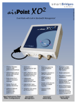
PoE Outdoor™
Quick Install Guide
This page intentionally left blank
PoE Outdoor
Page 1 of 18
Table of Contents
1. PoE Outdoor™................................................................. 4
2. Package Contents............................................................ 6
3. Installing the PoE Outdoor™............................................ 7
3.1 Grounding....................................................................................... 7
3.2 Mounting......................................................................................... 8
3.3 Ethernet and Power Connection .................................................... 9
3.3.1 Wall Plate Installation .......................................................... 11
3.3.2 Ethernet or RJ11 Cable Connection to
PoE Outdoor™ .................................................................... 12
3.4 LEDs Status ................................................................................. 13
3.5 Protection ..................................................................................... 13
4. Service and Support....................................................... 14
5. Frequently Asked Questions .......................................... 14
Appendix A - Specifications................................................................ 16
Appendix B –Warranty, License and Copyrights................................ 17
PoE Outdoor
Page 2 of 18
This page intentionally left blank
PoE Outdoor
Page 3 of 18
1.
PoE Outdoor™
PoE Outdoor™ is a unique Power over Ethernet Solution for outdoor
wireless installations. The PoE Outdoor™ delivers required operating
power and transmits data via the standard Category 5 Ethernet cable. It
eliminates the need for a separate 110/220 volt AC cable to the radio and
significantly reduces cabling and outlet requirements. The PoE Outdoor™
combines advanced protective and diagnostic features to bring
unmatched convenience in wireless network deployment.
Indicator LED
ETH OUT
Ground Lug
(On the lower side)
PWR
Reset Default
ETH IN
The PoE Outdoor™ is compatible to all IEEE 802.3af compliant
equipment. Powered by an industry standard 48V AC/DC adaptor, the
PoE Outdoor™ will provide sufficient power for devices connected up to
100m (328feet).
PoE Outdoor
Page 4 of 18
Protection
Features
Ethernet port protection and Special
Grounding Facility
Two layered protection on Data I/O and
Power lines
Short Circuit–Protection
Lightning Arrestor
Carrier Class
Advanced Diagnostics
Shielded RJ-45 Jacks
Auto Sensing of Cable length
Load Sensing
Diagnosis of Low supply voltage
Weather-proof
Remote Reset Switch
PoE Outdoor
Benefits
Special ground lug aids in direct and
efficient grounding of device to user
power ground, thus providing a ground
drain path for electrostatic or lightning
discharges (NEC 810.21 compliant)
Protects from heavy surge currents and
high voltage transients
Monitoring and protection ensures that
power supply is switched off
automatically while indicating the error
status due to short circuit on the output
ETH Out RJ45 jack.
Lightning Protection / Discharge (NEC
810.20 compliant)
Enables use of STP CAT5/e cables for
protection against electrostatic
discharge
Dynamically adjusts power supply to
compensate for voltage drop across the
length of the cable
Checks for PoE capable device and
power consumption
Switches off output power, indicating
error in power supply; hence easy to
troubleshoot
Detects presence of moisture in cables
Durable, heat-resistant NEMA 4 water
tight casing for reliable outdoor
deployment
Remotely restores the smartBridges
radio to default settings
Page 5 of 18
2.
Package Contents
•
•
•
•
•
•
•
•
•
•
PoE Outdoor
PoE Outdoor™ unit
AC Adapter
Cable for AC adapter
Wall Plate Unit
Earthing Tag , M6 Nut
RJ11 Plug
Pole Mount : U Bolts , M6 Nuts , M6 Spring Washers , M6 Plain Washers
Wall Plate : Wall Plugs , M4 Self Tap screws , M4 washers
Reset Pin
User Manual
Page 6 of 18
3.
Installing the PoE Outdoor™
The following steps should be carried out to install the PoE Outdoor™.
1. Grounding
2. Mounting: Wall or Pole mountable
3. Ethernet and Power Connection to the PoE Outdoor™,(Two ways to
do this):
a. Using the wall plate to carry Power and Data via the Ethernet
cable (RJ45).
b. Using the AC adapter directly to carry power via RJ11 (optional
input) and the Ethernet cable to carry only data via RJ45.
4. LED Status after connecting RJ45 Output from PoE Outdoor™ to the
smartBridges Device
5. Protection of the PoE Outdoor™ device
The details of these steps are in the next sub-sections.
3.1
Grounding
1. Crimp an AWG #10 earthing wire, to the Earth Tag provided.
2. Place this Earth Tag on the earthing stud at the bottom side of the
PoE Outdoor™.
3. Fasten it with the M6 Nut provided tightly to the earth Tag of the
PoE Outdoor™.
4. Connect the other end of the earth wire to the Power ground on
the premises.
Note: Grounding has to be done before mounting the PoE Outdoor™ on
the wall or pole.
PoE Outdoor
Page 7 of 18
3.2
Mounting
Mount the PoE Outdoor™ on the preferred wall or pole by using the
supplied U-Bolts, clamps, wall plugs and screws (shown in the diagram
below).
ETH OUT to Outdoor Radio
ETH IN from
Wall Plate
Ground Lug
PWR IN from RJ11
(only for direct powering)
PoE Outdoor
Page 8 of 18
3.3
Ethernet and Power Connection
A convenient installation can be achieved by using a single Ethernet cable
to run power and data to the PoE Outdoor™ unit. This is possible by using
the wall plate. Without compromising power supply or signal quality, the
total cable length can go up to 100meters (from the outdoor radio to the
PoE Outdoor™ to the Network/PC hub or wall power source). It is
recommended to keep the cable length from the Wall Plate to the PoE
Outdoor™, as short and direct as possible. The length of the RJ11 cable
and the Ethernet cable can be extended inside the premises, using
extension couplers and cables of suitable length.
Installation Diagram with Wall Plate
Steps for Ethernet and Power connection using the wall plate
1. Connect the 48V AC adapter to the AC mains inlet
2. Connect the RJ11 cable of the AC adapter to the Wall Plate.
Make sure the RJ11 connections are not reversed.
PoE Outdoor
Page 9 of 18
3. Using an RJ45 crimped CAT5 cable, connect the PC/Network to
the Wall Plate
4. Connect an outdoor rated, shielded Ethernet cable from the RJ45
output of the Wall Plate (Refer to section 3.3.1 for installing the
wall plate) to the ETH IN of the PoE Outdoor™ (refer to section
3.3.2 for connecting the Ethernet cables to the PoE Outdoor™).
5. Secure the outdoor rated Ethernet cable along the wall and outlet
hole properly. Provide strain relief on this CAT5 cable.
6. From the ETH OUT jack on the PoE Outdoor™, connect an
outdoor rated shielded CAT5 cable to the radio on the roof top or
tower. Provide strain relief for this CAT5 cable.
Installation Diagram without Wall Plate
Note: Optionally, the RJ11 cable can be directly connected to the
RJ11 input jack inside PoE OutdoorTM to power the device. In this
case, Ethernet input cable to the PoE Outdoor™ carries only data.
The output cable to the radio would carry both data and power.
PoE Outdoor
Page 10 of 18
3.3.1 Wall Plate Installation
The Wall Plate takes the RJ11 (for Power) and Ethernet IN (for Data) and
provides Ethernet OUT with Power over the Ethernet cable. The Ethernet
Out connector is inside the Wall Plate. The installation of Wall Plate is as
follows.
1. Remove the two screws holding the front and back of the Wall
Plate and check whether the RJ45 connector (ETH OUT) and
Wall Plate PCB are proper.
2. The Knock out plate at the center of the back cabinet should be
removed for taking the cable outside.
3. Connect the ETH IN and RJ11 in and check whether LED on the
Wall Plate PCB glows.
4. Push the slide switch to straight or cross position depending upon
whether the connection is to PC or network.
5. Connect the Ethernet output cable through the hole at the back of
the Wall Plate.
6. Fix the Wall Plate to the wall with the screws provided inside the
Wall Plate.
PoE Outdoor
Page 11 of 18
3.3.2 Ethernet or RJ11 Cable Connection to PoE Outdoor™
Note: Please do not insert the Ethernet cable or RJ11 cable with the
connector crimped into the ETH IN, ETH OUT or Power IN cable gland of
the PoE Outdoor™.
1. Unscrew the four corner screws on the top side of the PoE
Outdoor™ and remove the top cover.
2. Check whether the ETH IN, ETH OUT and Power IN cable glands
are punctured. At the time of shipping, the cable glands should be
in closed conditions. Use a small screwdriver to pierce a hole in
the cable gland. Do not let screwdriver touch the PCB
components.
3. Insert the uncrimped Ethernet cable from outside the PoE™
through the cable gland and into the device. Pull the cable for
about 100 mm.
4. Strip both the outer sleeve of the Ethernet cable, and the internal
twisted pairs of wires to 6 mm length.
5. Insert the wires into the RJ45 plug and crimp the plug.
6. Gently pull back the Ethernet Cable through the cable gland and
insert the RJ45 plug into the socket on the PCB.
7. To avoid accidental pulling of the Ethernet Cable, use a cable tie
over the Ethernet cable (on the inner side of the PoE Outdoor™).
8. After ETH IN and ETH OUT cables are connected, screw the top
cover back. (In the case of using direct power, make sure the
RJ11 DC In cable is connected)
9. Peel off the liner paper at the edges of the decorative label and
stick the label edges on the top cover.
PoE Outdoor
Page 12 of 18
3.4
LEDs Status
Upon connecting the RJ45 Output from PoE Outdoor™ to the
smartBridges Device, the statuses of the device is indicated with the
following LED color codes:
1.
Open Circuit
:
Green Blinking
2.
Short Circuit
:
Green, Amber and Blue Blinking
3.
smartBridges Classic mode
:
Solid Amber
4.
IEEE 802.3af mode
:
Solid Blue
5.
Undefined mode
:
Amber and Blue Blinking
3.5
Protection
Transient Voltage Suppressor (TVS)
Each of the four RJ45 data lines is clamped to 7.5V and the TVS provides
protection against High Voltage transients. The RJ11 power lines are
clamped to 60V. Grounding is done through the grounding lug at the back
of the PoE Outdoor™. The TVS offers very quick response time to
transient high voltages.
TVS Rating:
1.
Peak Pulse Power Capability: 1500 W (with a 10/100 micro second waveform )
2.
Repetition Rate (duty cycle): 0.01%
Gas Discharge Tube (GDT)
The GDT can handle large surges. The GDT triggers when exposed to
long duration surges. It has a high current rating to protect against surges.
Both the RJ45 data line and the RJ11 power lines are clamped to 90V
with independent GDTs.
GDT Rating:
Discharge Current Capability: 2.5KA (8/20 micro second waveform;10
times)
PoE Outdoor
Page 13 of 18
4.
Service and Support
This User Manual provides comprehensive information on Installation and
Configuration of PoE Outdoor™. If, however, you still have problems or
need further support, you can get in touch with us at:
http://www.smartbridges.com
You can also send your queries to [email protected]
Please register PoE Outdoor™ on our product registration page.
5.
Frequently Asked Questions
Does the PoE Outdoor™ work with non-smartBridges radios?
The PoE Outdoor™ will work with all smartBridges radios as well as IEEE
802.3af compliant non-smartBridges radios.
What is the power supply? Is it supplied along with the device?
The PoE Outdoor™ works with a 48V power supply, as specified by the
IEEE 802.3af standards. The power supply adaptor is currently supplied
along with the device.
What is the maximum length to which the Ethernet cable can be
pulled?
From the outdoor radio to the PoE Outdoor™ and from the PoE
Outdoor™ to the Hub/PC or the wall power source, the total cable length
can go up to 100m without compromising power supply or signal quality.
Is it compliant with NEC standards for installations?
The PoE Outdoor™ has Surge suppression capabilities (NEC 810.20
compliant).
Is there additional grounding protection?
Yes. The special grounding lug on the PoE Outdoor™ can be connected
to an earthwire for additional grounding. The PoE Outdoor™ grounding
capability is NEC 810.21 compliant.
PoE Outdoor
Page 14 of 18
What is the two-layered protection offered by the PoE Outdoor™?
The PoE Outdoor™ offers advanced two layered protection on the data
and power lines. Using GDTs and Transorbs, significant surge protection
is built into the PoE Outdoor™.
Does the PoE Outdoor™ work with existing smartBridges devices?
Yes. The PoE Outdoor™ will work with all classic smartBridges radios. It
has automatic output voltage adjustment for different cable lengths (for
smartBridges classic devices, upto 100m max.)
Is PoE Outdoor™ rated for outdoor installations?
Yes. The PoE Outdoor™ has a watertight NEMA box enclosure. It has a
wide operating temperature range of -40 Deg C to +60 Deg C (-40 F to
140 F) and 0 to 90% non-condensing humidity tolerance.
PoE Outdoor
Page 15 of 18
Appendix A - Specifications
Product No.
Ethernet Connector
AC/DC adaptor
PoEO DC out
SB2830
RJ-45
48V, RJ-11 cable
ETH Out Pin 5 of RJ-45 output –ve
ETH Out Pins 7, 8 of RJ-45 output +ve
IEEE 802.3af compliant
Ethernet Data Rate
Ethernet Data Cable
Number of Ethernet devices that
can power be powered
Detection of Low DC input
IEEE 802.3af signature detection
Input/Output status indication
1
Yes, with Output cut-off at low DC inputs
Yes
Green/ Orange / Blue LEDs
Surge Suppression
Yes (NEC 810.20 compliant)
Grounding Lug
Yes (NEC 810.21 compliant)
Remote Reset for smartBridges
radios
Operating Temperature
Output voltage
Relative Humidity
PoE Outdoor
10/100 Mbps
TIA/EIA-568, Category 5 cable UTP/STP (Maximum
length of 100m end-to-end)
Yes
-40 Deg C to +60 Deg C (-40 F to 140 F)
48V (for IEEE802.3af signature compliant devices)
Automatic output voltage adjustment for different
cable lengths (for smartBridges classic devices,
upto 100m max)
10 to 90% non-condensing
Dimensions
135mm x 80mm x 35mm
Unit Weight
450gm
Products Supported
All smartBridges Products and IEEE 802.3af
compliant products
Mounting
Pole or Wall mounting via 2pc U-Bolts and clamps
(supplied)
I/O Ports
Water-tight to NEMA 1, 4, 4X, 6, 12, 13; IP66
(EN60529) IK07 (EN30102)
Page 16 of 18
Appendix B –Warranty, License and Copyrights
Warranty Information
smartBridges warrants product to be free of defects, and agrees to repair or replace the
product that proves defective. PoE Outdoor™ is warranted for one year from date of
purchase. This warranty does not cover accidents, misuse, neglect, unauthorized product
modification, or acts of nature.
Please visit customer support area of smartBridges web site for making warranty claims.
smartBridges may elect to exchange the product or refund the full purchase price of the unit.
Except as expressly provided above, smartBridges makes no warranties or conditions,
express, implied, or statutory, including without limitation, the implied warranties of
merchantability and fitness for a particular purpose or infringement of any patent, copyright
or other intellectual property right. smartBridges shall not be liable for damage to other
property caused by any defects in this product, damages based upon inconvenience, loss of
use of the product, loss of time or data, commercial loss, or any other damages, whether
special, incidental, consequential, or otherwise, whether under theory of contract, tort
(including negligence), indemnity, product liability, or otherwise. smartBridges products are
not intended for use in medical, life saving, or life sustaining applications. In no event shall
smartBridges' liability exceed the normal purchase price for this product.
License
No license, express or implied, by estoppels or otherwise, to any intellectual property rights
is granted by this document.
Copyright & Trademarks
Copyright © 2003 smartBridges. All Rights Reserved. PoE Outdoor™ is a trademark of
smartBridges. All other trademarks and brand names mentioned in this Manual are
registered trademarks or trademarks of their respective owners.
PoE Outdoor
Page 17 of 18
Notes
PoE Outdoor
Page 18 of 18
PoE Outdoor
Page 19 of 18