1
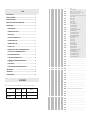
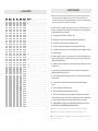
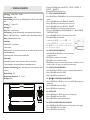
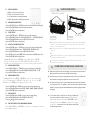
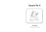
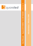
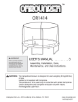
7、 MAINTENANCE To prolong the life of lighting, it is very important to do the maintenance work. The environment is hash outdoors, or if the lighting is idle for a long time, damp, dust can cause greater accumulation of dirt on its cover or housing. So it should be cleaned to maintain an optimum light output and at the same time to prevent it from corrupted by dust and acid gas. Cleaning frequency depends on the lighting operation frequency and the environment in which the fixture operates. Soft cloth and typical glass cleaning products should be used for cleaning. It is recommended to clean projector at least once every 20 days. Do not use any organic solvent,e.g.alcohol, to clean housing of the apparatus. TROUBLESHOOTING 8、 PROBLEM REASON AND ACTION Check the power connection is correct or not. The lighting can’t be Please detect the voltage. started normally Power supply is damaged or incorrect connected. Call a qualified personnel to fix it. Connection of control board is not correct. Call a qualified personnel to fix it. Please check the DMX connector and the power connection is connected correctly or not. It means having signal if it shows twinkling of the decimal point which in the lower right corner of the screen when exiting the screen saver. Please check the DMX address setting of lighting is correct or not. Check【CHMD】setting is correct or not. Please check whether the DMX line is near to the high voltage wire or not. In that case, it will damage or interfere the DMX electric circuit. Check whether the 【CAL】is started or not and the set value is too small. Check whether the【POW】is in over temperature protection situation or not, if yes, please take measures for ventilation. Out of console’s control The beam appears dim ,the brightness declines obviously SHINE BAR 12Q USER MANUAL Please read it carefully -11- Remark: AT01:R,G,B,RG,RB,GB AT02:R↑,R↓,G↑,G↓,B↑,B↓,W↑,W↓ AT03:R↑G↑,R↓G↓,R↑B↑,R↓B↓,B↑G↑,B↓G↓ AT04:R↑G↑B↑W↑,R↓G↓B↓W↓ AT05:(Rainbow effect)B,BG↑,BG,B↓G,G,GR↑,GR,G↓ R,R,RB↑,RB,R↓B AT06:R1→R2→R3 AT07:G1→G2→G3 AT08:B1→B2→B3 AT09:W1→W2→W3 AT10:R1G1→R2G2→R3G3 AT11:R1B1→R2B2→R3B3 AT12:G1B1→G2B2→G3B3 AT13:G3R2→R3G1→G2R1 AT14:R3B3R2G2→R1B1R3G3→R2B2R1G1 AT15:B3W2→B1W3→B2W1 AT16:R1G2B3→B1R2G3→G1B2R3 AT17:R1G2G3→G1R2G3→G1G2R3 AT18:G1B2B3→B1G2B3→B1B2G3 AT19:B1R2R3→R1B2R3→R1R2B3 AT20:R1←R2←R3 AT21:G1←G2←G3 AT22:B1←B2←B3 AT23:W1←W2←W3 AT24:R1G1←R2G2←R3G3 AT25:R1B1←R2B2←R3B3 AT26:G1B1←G2B2←G3B3 AT27:G3R2←R3G1←G2R1 AT28:R3B3R2G2←R1B1R3G3←R2B2R1G1 AT29:B3W2←B1W3←B2W1 AT30:R1G2B3←B1R2G3←G1B2R3 AT31:R1G2G3←G1R2G3←G1G2R3 AT32:G1B2B3←B1G2B3←B1B2G3 AT33:B1R2R3←R1B2R3←R1R2B3 76-80 AUTO 5 81-85 AUTO 6 86-90 AUTO 7 91-95 AUTO 8 96-100 AUTO 9 101-105 AUTO 10 106-110 AUTO 11 111-115 AUTO 12 116-120 AUTO 13 5.OPERATION MENU .......................................................................................... - 5 - 121-125 AUTO 14 126-130 AUTO 15 5.1 BUTTON OPERATION ........................................................................................ - 7 - 131-135 AUTO 16 136-140 AUTO 17 141-145 AUTO 18 5.3 STATIC SETTING ................................................................................................ - 7 - 146-150 AUTO 19 151-155 AUTO 20 5.4 COLOR CAST CALIBRATION SETTING .................................................................. - 7 - 156-160 AUTO 21 5.5 CHANNEL MODE SETTING ................................................................................ - 7 - 161-165 AUTO 22 166-170 AUTO 23 5.6 DIMMING MODE SETTING ................................................................................ - 7 - 171-175 AUTO 24 176-180 AUTO 25 181-185 AUTO 26 5.8 RUNNING THE AUTO-RUN,AUTO-PROGRAMMING PROGRAM ............................ -7 - 186-190 AUTO 27 191-195 AUTO 28 5.9 EDITTING THE AUTO-PROGRAMMING PROGRAM .............................................. -8 - 196-200 AUTO 29 201-205 AUTO 30 206-210 AUTO 31 5.11 LIGHTING SETTING PARAMETER RESET ........................................................... - 8 - 211-215 AUTO 32 216-220 AUTO 33 5.12【PROG】AUTO-PROGRAMMING PARAMETER RESET ...................................... -8 - 221-225 CHASE1 226-230 CHASE2 231-235 CHASE3 236-255 Reserved 0—255 Auto speed,fast->slow,(AT01-AT05:0-255S,AT06-AT33:0-25.5S) INDEX 1.SAFETY GUIDELINE .......................................................................................... - 2 2.TECHNICAL PARAMETER .................................................................................. - 3 3.LIGHTING INSTALLATION .................................................................................. - 4 4.POWER SUPPLY-CONTROL SIGNAL CONNECTIONS ............................................ - 4 - 5.2 DMX ADDRESS CODE SETTING .......................................................................... - 7 - 5.7 DISPLAY SETTING .............................................................................................. -7 - 5.10 LIGHTING INFORMATION VIEW ...................................................................... - 8 - 5.13 LIGHTING RESET .............................................................................................. -8 5.14 LIGHTING PARAMETER DOWNLOADING EACH OTHER ..................................... - 8 - - - CH8 CH16 6. DMX PROTOCOL ..........................................................................................- 9 - 7. MAINTENANCE .......................................................................................... -11- 0-10 ................................................................................... -11- 12-50 8. TROUBLESHOOTING Virtual colour wheel 11 51 52-90 ACCESSORIES CH2 - - CH9 CH17 These items are packed together with the Lighting,please check: This manual Power cable Quantity Unit 1 Pc 1 Remark - CH7 CH10 CH18 Light Blue (Red=0, Green=full, Blue =full, White=0)(step) Red=0, Green=full, Blue->down, White=0(proportional) Green (Red=0, Green=full, Blue =0, White=0)(step) Red->up, Green=full, Blue=0, White=0(proportional) 131 Yellow (Red=full, Green=full, Blue=0, White=0)(step) 132-170 Red=full, Green->down, Blue=0, White=0(proportional) 211 - Red=0, Green->up,Blue =full, White=0(proportional) 92-130 172-210 Pc Blue (Blue=full, Red+Green+White=0)(step) 91 171 Name No effect Red(Red=full, Green=0, Blue=0, White=0)(step) Red=full, Green=0, Blue->up, White=0(proportional) Magenta (Red=full, Green=0, Blue=full, White=0)(step) 212-250 Red -> down, Green=0, Blue=full, White=0(proportional) 251-255 Blue (Red=0, Green=0, Blue=full, White=0)(step) 0-10 Use menu setting dimmer mode 11-20 Dimmer off 21-30 Dimmer 1 31-40 Dimmer 2 41-50 Dimmer 3 51-60 Dimmer 4 61-254 Use menu setting dimmer mode 255 -10- Reset(at least 5S) 1、SAFETY GUIDELINE 6、DMX PROTOCOL 2CH 5CH 7CH 10CH 18CH Value - CH1 CH1 CH1 CH1 0-255 Dim all - CH2 CH2 CH2 - 0-255 Red - CH3 CH3 CH3 - 0-255 Green - CH4 CH4 CH4 - 0-255 Blue - CH5 CH5 CH5 - 0-255 White - - - - CH2 0-255 Red 1 - - - - CH3 0-255 Green 1 - - - - CH4 0-255 Blue 1 - - - - CH5 0-255 - - - - CH6 0-255 - - - - CH7 0-255 Green 2 - - - - CH8 0-255 Blue 2 - - - - CH9 0-255 White 2 - - - - CH10 0-255 Red 3 - - - - CH11 0-255 Green 3 - - - - CH12 0-255 Blue 3 - - - - CH13 0-255 White 3 0-10 No strobe CH1 - - - CH6 - CH6 CH7(CH7 Prior to CH9) CH14 CH15(CH15 Prior to CH17) Function Please keep this manual for further inquire reference. Please make sure they also have this user manual if you sell this Lighting to other users. Each unit is packed properly by the manufacturer. Please operate this Lighting according to the user manual. Any damage caused by improper use will not be assumed by the manufacturer. When receiving the lighting ,please dispose the carton, check and inspect there is any damage or not. Should there be any damage caused by transportation,do not use the lighting and consult your dealer or the manufacturer. This lighting can be used indoors and outdoors, IP65. The lighting is only intended for installation and operation by qualified personnel. White 1 Do not mount the lighting directly onto inflammable surface. Red 2 Ensure power supply voltage correspond to device requirements before running. 11-90 Strobe,slow->fast 91-170 Random Strobe,slow->fast 171-255 Electronic Squarewave,slow->fast 0-5 No effect 6-10 WHITE 1:3200K 11-15 WHITE 2:3400K 16-20 WHITE 3:4200K 21-25 WHITE 4:4900K 26-30 WHITE 5:5600K 31-35 WHITE 6:5900K 36-40 WHITE 7:6500K 41-45 WHITE 8:7200K 46-50 WHITE 9:8000K 51-55 WHITE 10:8500K 56-60 AUTO 1 61-65 AUTO 2 66-70 AUTO 3 71-75 AUTO 4 It is essential that each lighting is correctly earthed and that electrical installation conforms to all relevant standards. When the lighting is hanged to a high place, please use a safety cord provided to pass through the lighting handles as a secondary safety fixing for safety seasons. For details, refer to “LIGHTING INSTALLATION” section. Avoid direct exposure to the light from the lamp(specially for people with epilepsy). The light is harmful to eyes. Do not project the beam onto inflammable surfaces. The minimum distance between the lighting and irradiated object should be 2 m. Exterior surface temperature of the lighting will be 65℃ when working,please do not touch it with bare hands . To prevent electric shocking, please do not touch the power cord when the lighting is running. Never let the power cord mix with other cables. The LED lens should be changed if deeply scratched or cracked. There is no user serviceable parts inside the lighting. Before using the device, please check whether the covers or housing are well installed or not, and whether the screws are installed firmly or not. Do not open the housing and never operate the lighting with the covers removed. Always disconnect a lighting from the power supply when the device is not in use or before cleaning it or before attempting any maintenance work! Electrical connection must only be carried out by qualified personnel. Please use the original packing material for second transportation. If you have any questions or suggestions, please do not hesitate to consult your dealer or our factory. -9- -2- 2、TECHNICAL PARAMETER Input Voltage: AC100V-AC240V, 50/60HZ; Power Consumption: 120W ; Lamp Specifications:12 pcs four in one(RGBW) high-efficiency 10W LED, rated life 50000 hours; ; Lens Angle:25º(Optional:45°) Spot Angle:40º; Color:RGBW linear color mixing; Color Temperature:color cast calibration setting、color temperature output inside device; Dimmer: 0-100% linearly dimming, 5 types dimmer modes,smooth dimming, flicker-free; Shutter:independent electronic strobe; 2)Press the【UP/DOWN】button to select【AT01】…【AT33】,【SPEED】,【 CHASE01】…【CHASE03】 3)Press the【ENTER】button to start running. 5.9 EDIT AUTO-PROGRAMMING PROGRAM 1) Press the【ENTER】button in【PROGRAM】menu, then enter to the editing auto-programming program. 2) Press the【UP/DOWN】button to select【CHASE01】…【CHASE03】 3) Press the【ENTER】button for confirmation and enter to the next menu. 4) Press the【UP/DOWN】button to select【SCENE01】…【SCENE20】 5) Press the【ENTER】button for confirmation and enter to the next menu. , 【GREEN1 】……【WHITE3】 , 【SHUT】 , 6) Then press the【UP/DOWN】button to select【RED1】 【TIME】 , 【WAIT】 , 【USE】 7) Press the【UP/DOWN】button to set up the parameter which are needed. 8) Press the【ENTER】button to escape and save. Illustrations:When【USE】 is set to be【NO】,or the parameter of【TIME】 is 0, it will not run this scene. When 【WAIT】is set to be FADE time, the running process isas the right chart showing. Control Mode: Standard DMX512,3 pin interfaces; 5 channel modes; Master/slave mode,no need to set up the master and slave manually, will receive the main engine data automatically; 33 auto-running modes,rainbow channel and rainbow effect; Other Functions: Self-programming function, 3 chases,each chase has 20 scenes,fade function; Lighting setting data、self-programming data can be downloaded each other; Temperature Control Protection:Both of lamp holder and base have temperature control protection; Waterproof Grade: IP65; Work Environment Temperature: -20°C~40°C; Net Weight:5.6 Kg; 5.10 CHECK THE LIGHTING INFORMATION 1) Press the【ENTER】button in【INFO】menu, then enter to the checking the lighting information. 2) 【SOFT】button is for software version information. 3) 【LEDs】button is for the LED quantity information. 4) 【POW】button is for the current information of power reduction. It is 100% output in normal conditions, but 80% or 50% output in over temperature protection situation. 5.11 LIGHTING SETTING PARAMETER RESET 1) Press the【ENTER】button in【ST L】menu, then enter to the lighting setting parameter reset. 2) Press the【UP/DOWN】button to select【YES】. 3) Press the【ENTER】button to escape and save. 5.12 【PROG】AUTO-PROGRAMMING PARAMETER RESET 1) Press the【ENTER】button in【PR L】menu, then enter to the【PROG】auto-programming parameter reset. 2) Press the【UP/DOWN】button to select【YES】. 3) Press the【ENTER】button to escape and save. DIMENSION 5.13 LIGHTING RESET 1) Press the【ENTER】button in【REST】menu, then enter to the lighting reset. 2) Press the【UP/DOWN】button to select【YES】. 3) Press the【ENTER】button for confirmation of lighting reset. 5.14 LIGHTING PARAMETER DOWNLOADING EACH OTHER 1) Press the【ENTER】button in【SEND】menu, then enter to sending parameter to other lightings. 2) Press the【UP/DOWN】button to select【YES】. 3) Press the【ENTER】button to confirm sending. -3- -8- 5.1 1) 2) 3) 4) 5.2 BUTTON OPERATION 3、 MENU:To return to the previous menu. ENTER:Enter to the next menu or save. UP:Menu selection or increasing the parameter. DOWN:Menu selection or decreasing the parameter. LIGHTING INSTALLATION MOUNTING HOLE FOR LAMP HOOK SAFETY RING DMX ADDRESS CODE SETTING 1) Press the 【ENTER】 button in 【ADDR】 menu, then enter to the DMX address code setting. 2) Press the【UP/DOWN】button to select【1-512】numerical value. 3) Press the【ENTER】button to escape and save. 5.3 STATIC SETTING 1) Press the【ENTER】button in 【STAT】menu, then enter to the static setting. 2) Press the【UP/DOWN】 button to select 【RED1】, 【GREEN1】……【WHITE3】and【SHUT】. 3) Press the【UP/DOWN】button to set up the【0-255】numerical value. 4) Press the【ENTER】button to escape and save. THE SCREW HOLE The lighting can be hanged on the high place with using the lamp hooks (as showed in 5.4 COLOR CAST CALIBRATION SETTING 1) Press the【ENTER】button in 【CAL】menu, then enter to the color cast calibration setting. 2) Press the【UP/DOWN】button to select 【RED】 , 【GREEN】 , 【BLUE】 , 【WHITE】 3) Press the【UP/DOWN】button to set up the【0-255】numerical value. 4) On the【USE】interface, pressing【ON】button means valid, otherwise【OFF】button invalid. 5) Press the【ENTER】button to escape and save. picture 1). Use the safety cord provided to pass through the bottom safe ring and hang it as a second safety fixing. The lighting also can place on the ground and make sure balance stand ,as showed in picture 2. Note: Ensure support loading ability at least 10 times more than product weight,and make sure lighting be firmly installed. Illustrations: When pressing the【ON】button which means valid on the【USE】 interface, the actual output value of RED,GREEN,BLUE,WHITE is output in accordance with the percentage which the color cast calibration value divides 255. 5.5 CHANNEL MODE SETTING 1) Press the【ENTER】button in 【CHMD】menu, then enter to the channel mode setting. 2) Press the【UP/DOWN】button to select【18CH】 , 【10CH】 , 【7CH】 , 【5CH】,【2CH】 3) Press the【ENTER】button to escape and save. 5.6 DIMMING MODE SETTING Illustrations:When setting【OFF】 in【DIM】menu, there will be no delay dimming effect. The dimming speed of DIM1-DIM4 is from fast to slow. It will be set【OFF 】automatically in【DIM】menu when showing the shutter effect. The lighting must be installed by the qualified personnel. Please install it at the place where no one goes through. 4、 5.8 RUN THE AUTO-RUN, AUTO-PROGRAMMING PROGRAM 1)Press the【ENTER】button in【AUTO】menu, then enter to the running the auto-run, auto-programming program. -7- POWER SUPPLY-CONTROL SIGNAL CONNECTIONS Make the XLR signal line connect with the lighting, one port connects with the output port of lighting, another one connects with the input port of another lighting. Due to the output and input of the lighting keep connecting all the time, so the DMX circuit still can be keep connecting when the power of certain unit occurs turn-off. XLR signal line only can be used in series connection pattern(the amount of the lighting can not be more than 32 PCS), not available in parallel connection pattern. Must add a signal amplifier if the length of signal line exceeds 60M between controller and lighting or between two lightings. In the controller mode, at the last fixture in the chain, the DMX output has to be connected with a DMX terminator. The DMX terminator is simply a connector with a resistor about 120Ω(OHM)connected across pins 2 and 3 of the Canon plug(please see the picture in the right).It can prevent the noise and reflection caused by DMX 512 signal during transmission. 1) Press the【ENTER】button in【DIM】menu, then enter to the dimming mode setting. 2) Press the【UP/DOWN】button to select【OFF】 , 【DIM1】 , 【DIM2】 , 【DIM3】and【DIM4】 3) Press the【ENTER】button to escape and save. 5.7 DISPLAY SETTING 1) Press the【ENTER】button in【DISY】menu, then enter to the display setting. 2) Press the【UP/DOWN】button to select【ON】 , 【2 MINITES OFF】 3) Press the【ENTER】button to escape and save. PICTURE TWO PICTURE ONE -4- The transmission speed of DMX 512 signal is very quick. It will affect the signal transmission if any damage of the signal line, the weld is not firm or bad connection etc The connector with 3 pins XLR is more universal than the one with 5 pins XLR. 3 pins XLR:PIN 1:GND,PIN 2:- signal,PIN 3:+ signal. 5 pins XLR:PIN 1:GND,PIN 2:- signal,PIN 3:+ signal,PIN4/PIN5:UNUSED. There can’t be more than 12 PCS of lightings for series connection pattern when using 220V AC; it can’t exceed 6 PCS lightings for series connection pattern when using 110V AC. CTST(Color temperature set) AUTO(Auto) POWER OUT PROG(Program) DMX OUT POWER IN 5、 Tab TO TERMINATOR DMX CONSOLE OPERATION MENU Level 1 ADDR(Address) 001-512 STAT(Static control) R1 G1 B1 W1 R2 G2 B2 W2 R3 G3 B3 W3 SHUT SET(Set) CAL(Calibration) CH(Channel mode) D(Dimming mode) DISY(Display set) Level 2 0-255 * 0-255 * 0-255 * 0-255 * 0-255 * 0-255 * 0-255 * 0-255 * 0-255 * 0-255 * 0-255 * 0-255 * 0-255 * R(Red) G(Green) B(Blue) W(White) USE 18CH 10CH 7CH 5CH 2CH OFF D1 D2 D3 D4 ON(Permanent on) 2 OF (2 minutes off) -5- Level 3 Level 4 INFO(Information) 0-255 0-255 0-255 0-255 YES/NO LOAD(Load) REST(Reset) SEND(Send) CT01 R(Red) 0-255 . . . CT10 AT01 . . . AT33 ATSP(Auto speed) CHS1(Chase 1) CHS2(Chase 2) CHS3(Chase 3) CHS1(Chase 1) . . . . . . . . . . . . . . . . . . CHS3(Chase 3) SOFT(Software version) LEDs G(Green) B(Blue) W(White) 0-255 0-255 0-255 RUN.. * RUN.. * RUN.. * RUN.. * RUN.. * 0-255(S) RUN.. * RUN.. * RUN.. * SC01(Scene 1) . . . . . . . . . . . . . . . . . SC25(Scene 25) R1 G1 B1 W1 R2 G2 B2 W2 R3 G3 B3 W3 SHUT AUTO ATSP TIME WAIT USE 0-255 0-255 0-255 0-255 0-255 0-255 0-255 0-255 0-255 0-255 0-255 0-255 0-255 NONE,AT01-AT33 0-255(S) 0-255(S) 0-25.5(S) YES/NO Vx.x xxR xxG xxB xxW POW(Power reduction) 100%/80%/50% ST L(Setting load) YES/NO PR L(Program load) YES/NO YES/NO YES/NO Illustrations: When the menu is set as the information of * position, the projector will be set automatically to be the main engine and then send data to external. Other projectors can receive these data and run synchronously with the main engine. It still be run according to these setting parameter even if power reconnection after power off . When setting YES in【ST L】menu, The parameter will bereset to be the factory default value as which with underline of above chart. -6-