1
20XM51-00 E3 – 2014-02-24
User Manual
XM51 – ESMexpress® COM
with PowerPC® QorIQ™
P4080
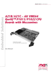
Module without cover and frame
XM51 - ESMexpress® COM with PowerPC® QorIQ™ P4080
XM51 - ESMexpress® COM with PowerPC® QorIQ™ P4080
The XM51 is a multi-core computer-on-module based on the Freescale™
PowerPC® QorIQ™ family. Together with an application-specific carrier board it
forms a semi-custom solution for industrial, harsh, mobile and mission-critical
environments.
The XM51 is built around a QorIQ™ P4080, P4040 or P3041 running at
frequencies between 1.2 and 1.5 GHz. All types have multi-core performance and
advanced processing functions (incl. encryption), but the XM51 is still scalable to
individual needs. The eight-core P4080 is a high-end number cruncher, while the
P3041 aims at power and cost efficiency. The entire board draws a maximum power
of 32 W and supports extended operating temperatures in all configurations.
The COM has up to 16 GB of soldered ECC main memory driven by two
independent controllers. The two RAM banks can be assigned to processor cores to
avoid access conflicts and assure deterministic behavior. This facilitates building up
certifiable solutions for safety-critical avionics or railway applications. Up to 512
KB industrial, non-volatile FRAM and 256 MB Flash round out the XM51's
onboard memory. Further capacity can be added on the carrier board as needed via
high-speed serial busses, i.e. USB or SATA.
All interfaces routed from the QorIQ™ processor are available on any
ESMexpress® carrier board. Those include four USB 2.0 host ports and one USB
client realized using a UART-to-USB converter, two Gigabit Ethernet channels, dual
3-Gbit SATA, and two PCI Express® x1 links. The latter support PCIe® 2.x with
data rates of 5 Gbit/s per lane.
The XM51 is qualified for operation in a -50°C to +85°C conduction or convection
cooled environment. As all ESMexpress® modules it is embedded in a covered
frame. This ensures EMC protection and allows efficient conductive cooling. Air
cooling is also possible by applying a heat sink on top of the cover. ESMexpress®
modules are firmly screwed to a carrier board and come with rugged industryproven connectors supporting high frequency and differential signals. Only soldered
components are used to withstand shock and vibration, and the design is optimized
for conformal coating. All ESMexpress® modules support a single 95 x 125 mm
form factor.
For evaluation and development purposes an ATX carrier board is available. The
ESMexpress® module can be evaluated on a COM Express® carrier board via an
adapter from ESMexpress® to COM Express®.
MEN Mikro Elektronik GmbH
20XM51-00 E3 – 2014-02-24
2
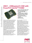
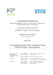
Diagram
Diagram
Options
B Onboard connector
Gigabit Ethernet
64‐bit
ECC DDR3 SDRAM
64‐bit
ECC DDR3 SDRAM
UART‐to‐USB USB Client
PCI Express x1
USB 2.0
PCI Switch/ PCIe x1
USB Hub
PCI x1
PCIe‐to‐SATA
PowerPC®
QorIQ™
P4080 (eight‐core)
or
P4040 (quad‐core)
or
P3041 (quad‐core)
Flash
FRAM
I2C
EEPROM
RTC
GPIO/LED
I2C
Watchdog
ESMexpress® Connectors
MEN Mikro Elektronik GmbH
20XM51-00 E3 – 2014-02-24
B
3
Technical Data
Technical Data
CPU
• Freescale™ QorIQ™ P4080 or P4040 or P3041
- 1.2 GHz up to 1.5 GHz
- Eight/four high-performance Power Architecture e500mc cores
Memory
• 32 KB instruction and data L1 cache and private 128 KB L2 cache per processor
core
• Up to 16 GB SDRAM system memory
- Soldered
- DDR3 with ECC support
- Up to 667 MHz memory bus frequency, depending on processor
configuration
- P4080/P4040 with two independent memory controllers, P3041 with one
controller
• Up to 256 MB boot/program Flash
• 128 KB non-volatile FRAM
• Serial EEPROM 8 kbits for factory settings
Serial ATA (SATA)
•
•
•
•
Two ports via ESMexpress® connector
SATA Revision 2.x support
Transfer rates up to 300 MB/s (3 Gbit/s)
Via PCIe®-to-SATA bridge
USB
• Four USB 2.0 host ports via ESMexpress® connector
- OHCI and EHCI implementation
- Data rates up to 480 Mbit/s
• One USB client port via ESMexpress® connector
- Via UART-to-USB converter
- Data rates up to 230.4 kbit/s
- 16-byte transmit/receive buffer
- Handshake lines: none
Ethernet
• Two 10/100/1000Base-T Ethernet channels
• Two LED signals per channel for LAN link and activity status and connection
speed
• Accessible via ESMexpress® connector
MEN Mikro Elektronik GmbH
20XM51-00 E3 – 2014-02-24
4
Technical Data
PCI Express®
• Two x1 links via ESMexpress® connector
• PCIe® 2.x support
• Data rate 500 MB/s in each direction (5 Gbit/s per lane)
GPIO
• 3 lines via ESMexpress® connector
I2C Bus
• 1 interface via ESMexpress® connector
Miscellaneous
• Real-time clock (with supercapacitor or battery backup on the carrier board)
• Temperature sensor, power supervision and watchdog
Electrical Specifications
• Supply voltage/power consumption:
- +12V (9..16 V), 32 W max.
Mechanical Specifications
• Dimensions: 95 mm x 125 mm (conforming to ESMexpress® specification)
• ESMexpress® PCB mounted between a frame and a cover
• Weight: 230 g (incl. cover and frame)
Environmental Specifications
• Temperature range (operation): -50..+85°C Tcase (ESMexpress® cover/frame)
(qualified components)
• Temperature range (storage): -50..+85°C
• Relative humidity (operation): max. 95% non-condensing
• Relative humidity (storage): max. 95% non-condensing
• Altitude: -300 m to +3000 m
• Shock: 15 g, 11 ms (EN 60068-2-27)
• Bump: 10 g, 16 ms (EN 60068-2-29)
• Vibration (sinusoidal): 1 g, 10 Hz – 150 Hz (EN 60068-2-6)
• Conformal coating on request
MTBF
• 475 088 h @ 40°C according to IEC/TR 62380 (RDF 2000)
Safety
• PCB manufactured with a flammability rating of 94V-0 by UL recognized
manufacturers
MEN Mikro Elektronik GmbH
20XM51-00 E3 – 2014-02-24
5
Technical Data
EMC
• EMC behavior depends on the system and housing surrounding the
ESMexpress® module.
• MEN has performed general, successful EMC tests for ESMexpress® using the
XC1 evaluation carrier according to:
- EN 55022 (radio disturbance)
- IEC 61000-4-2 (ESD)
- IEC 61000-4-3 (electromagnetic field immunity)
- IEC 61000-4-4 (burst)
- IEC 61000-4-5 (surge)
- IEC 61000-4-6 (conducted disturbances)
BIOS
• U-Boot Universal Boot Loader
Software Support
• VxWorks®
• Linux (on request)
• For more information on supported operating system versions and drivers see
online data sheet.
MEN Mikro Elektronik GmbH
20XM51-00 E3 – 2014-02-24
6
Configuration Options
Configuration Options
CPU
• QorIQ™ P4080 or P4040 or P3041
- P4080: eight cores, up to 16 GB DDR3 RAM (two controllers), 2 MB L3
cache, 30 W max. (processor)
- P4040: four cores, up to 16 GB DDR3 RAM (two controllers), 2 MB L3
cache, 24 W max. (processor)
- P3041: four cores, up to 8 GB DDR3 RAM (one controller), 1 MB L3 cache,
18.2 W max. (processor)
• All processors available with 1.2 GHz, 1.33 GHz or 1.5 GHz
Memory
• System RAM
- One or two memory banks, depending on processor type
- 2 GB, 4 GB, 8 GB
- 16 GB (only possible with two banks, P4080 or P4040)
- Currently only 2 GB are supported by U-Boot and BSP
• Boot/program Flash
- 64 MB, 128 MB or 256 MB
• FRAM
- 0 KB or 128 KB
Software Support
• Linux; processors are supported, U-Boot support already implemented
Please note that some of these options may only be available for large volumes.
Please ask our sales staff for more information.
For available standard configurations see online data sheet.
MEN Mikro Elektronik GmbH
20XM51-00 E3 – 2014-02-24
7
Product Safety
Product Safety
!
Electrostatic Discharge (ESD)
Computer boards and components contain electrostatic sensitive devices.
Electrostatic discharge (ESD) can damage components. To protect the board and
other components against damage from static electricity, you should follow some
precautions whenever you work on your computer.
• Power down and unplug your computer system when working on the inside.
• Hold components by the edges and try not to touch the IC chips, leads, or
circuitry.
• Use a grounded wrist strap before handling computer components.
• Place components on a grounded antistatic pad or on the bag that came with the
component whenever the components are separated from the system.
• Store the board only in its original ESD-protected packaging. Retain the original
packaging in case you need to return the board to MEN for repair.
MEN Mikro Elektronik GmbH
20XM51-00 E3 – 2014-02-24
8
About this Document
About this Document
This user manual is intended only for system developers and integrators, it is not
intended for end users.
It describes the hardware functions of the board, connection of peripheral devices
and integration into a system. It also provides additional information for special
applications and configurations of the board.
The manual does not include detailed information on individual components (data
sheets etc.). A list of literature is given in the appendix.
History
Issue
Date
E1
First issue
2011-12-23
E2
General update, minor errors corrected; improved
and corrected watchdog description; corrected UBoot image description
2013-02-04
E3
Removed all ANSI-VITA 59 references.
2014-02-24
MEN Mikro Elektronik GmbH
20XM51-00 E3 – 2014-02-24
Comments
9
About this Document
Conventions
This sign marks important notes or warnings concerning the use of voltages which
can lead to serious damage to your health and also cause damage or destruction of
the component.
!
italics
bold
monospace
This sign marks important notes or warnings concerning proper functionality of the
product described in this document. You should read them in any case.
Folder, file and function names are printed in italics.
Bold type is used for emphasis.
A monospaced font type is used for hexadecimal numbers, listings, C function
descriptions or wherever appropriate. Hexadecimal numbers are preceded by "0x".
comment
Comments embedded into coding examples are shown in green color.
hyperlink
Hyperlinks are printed in blue color.
The globe will show you where hyperlinks lead directly to the Internet, so you can
look for the latest information online.
IRQ#
/IRQ
Signal names followed by "#" or preceded by a slash ("/") indicate that this signal is
either active low or that it becomes active at a falling edge.
in/out
Signal directions in signal mnemonics tables generally refer to the corresponding
board or component, "in" meaning "to the board or component", "out" meaning
"coming from it".
Vertical lines on the outer margin signal technical changes to the previous issue of
the document.
MEN Mikro Elektronik GmbH
20XM51-00 E3 – 2014-02-24
10
About this Document
Legal Information
Changes
MEN Mikro Elektronik GmbH ("MEN") reserves the right to make changes without further notice to any products
herein.
Warranty, Guarantee, Liability
MEN makes no warranty, representation or guarantee of any kind regarding the suitability of its products for any
particular purpose, nor does MEN assume any liability arising out of the application or use of any product or
circuit, and specifically disclaims any and all liability, including, without limitation, consequential or incidental
damages. TO THE EXTENT APPLICABLE, SPECIFICALLY EXCLUDED ARE ANY IMPLIED
WARRANTIES ARISING BY OPERATION OF LAW, CUSTOM OR USAGE, INCLUDING WITHOUT
LIMITATION, THE IMPLIED WARRANTIES OF MERCHANTABILITY AND FITNESS FOR A
PARTICULAR PURPOSE OR USE. In no event shall MEN be liable for more than the contract price for the
products in question. If buyer does not notify MEN in writing within the foregoing warranty period, MEN shall
have no liability or obligation to buyer hereunder.
The publication is provided on the terms and understanding that:
1. MEN is not responsible for the results of any actions taken on the basis of information in the publication, nor
for any error in or omission from the publication; and
2. MEN is not engaged in rendering technical or other advice or services.
MEN expressly disclaims all and any liability and responsibility to any person, whether a reader of the publication
or not, in respect of anything, and of the consequences of anything, done or omitted to be done by any such person
in reliance, whether wholly or partially, on the whole or any part of the contents of the publication.
Conditions for Use, Field of Application
The correct function of MEN products in mission-critical and life-critical applications is limited to the
environmental specification given for each product in the technical user manual. The correct function of MEN
products under extended environmental conditions is limited to the individual requirement specification and
subsequent validation documents for each product for the applicable use case and has to be agreed upon in writing
by MEN and the customer. Should the customer purchase or use MEN products for any unintended or
unauthorized application, the customer shall indemnify and hold MEN and its officers, employees, subsidiaries,
affiliates, and distributors harmless against all claims, costs, damages, and expenses, and reasonable attorney fees
arising out of, directly or indirectly, any claim or personal injury or death associated with such unintended or
unauthorized use, even if such claim alleges that MEN was negligent regarding the design or manufacture of the
part. In no case is MEN liable for the correct function of the technical installation where MEN products are a part
of.
Trademarks
All products or services mentioned in this publication are identified by the trademarks, service marks, or product
names as designated by the companies which market those products. The trademarks and registered trademarks
are held by the companies producing them. Inquiries concerning such trademarks should be made directly to those
companies.
Conformity
MEN products are no ready-made products for end users. They are tested according to the standards given in the
Technical Data and thus enable you to achieve certification of the product according to the standards applicable in
your field of application.
MEN Mikro Elektronik GmbH
20XM51-00 E3 – 2014-02-24
11
About this Document
RoHS
Since July 1, 2006 all MEN standard products comply with RoHS legislation.
Since January 2005 the SMD and manual soldering processes at MEN have already been completely lead-free.
Between June 2004 and June 30, 2006 MEN’s selected component suppliers have changed delivery to RoHScompliant parts. During this period any change and status was traceable through the MEN ERP system and the
boards gradually became RoHS-compliant.
WEEE Application
The WEEE directive does not apply to fixed industrial plants and tools. The compliance is the responsibility of the
company which puts the product on the market, as defined in the directive; components and sub-assemblies are
not subject to product compliance.
In other words: Since MEN does not deliver ready-made products to end users, the WEEE directive is not
applicable for MEN. Users are nevertheless recommended to properly recycle all electronic boards which have
passed their life cycle.
Nevertheless, MEN is registered as a manufacturer in Germany. The registration number can be provided on
request.
Copyright © 2014 MEN Mikro Elektronik GmbH. All rights reserved.
Germany
MEN Mikro Elektronik GmbH
Neuwieder Straße 3-7
90411 Nuremberg
Phone +49-911-99 33 5-0
Fax +49-911-99 33 5-901
E-mail [email protected]
www.men.de
MEN Mikro Elektronik GmbH
20XM51-00 E3 – 2014-02-24
France
MEN Mikro Elektronik SAS
18, rue René Cassin
ZA de la Châtelaine
74240 Gaillard
Phone +33 (0) 450-955-312
Fax +33 (0) 450-955-211
E-mail [email protected]
www.men-france.fr
USA
MEN Micro Inc.
860 Penllyn Blue Bell Pike
Blue Bell, PA 19422
Phone (215) 542-9575
Fax (215) 542-9577
E-mail [email protected]
www.menmicro.com
12
Contents
Contents
1 Getting Started . . . . . . . . . . . . . . . . . . . . . . . . . . . . . . . . . . . . . . . . . . . . . . . .
1.1 Map of the Board. . . . . . . . . . . . . . . . . . . . . . . . . . . . . . . . . . . . . . . . .
1.2 First Operation. . . . . . . . . . . . . . . . . . . . . . . . . . . . . . . . . . . . . . . . . . .
1.3 Installing Operating System Software. . . . . . . . . . . . . . . . . . . . . . . . .
16
16
18
20
2 Functional Description . . . . . . . . . . . . . . . . . . . . . . . . . . . . . . . . . . . . . . . . . .
2.1 Power Supply. . . . . . . . . . . . . . . . . . . . . . . . . . . . . . . . . . . . . . . . . . . .
2.2 Board Supervision . . . . . . . . . . . . . . . . . . . . . . . . . . . . . . . . . . . . . . . .
2.2.1
Temperature and Voltage. . . . . . . . . . . . . . . . . . . . . . . . . . . .
2.2.2
Watchdog. . . . . . . . . . . . . . . . . . . . . . . . . . . . . . . . . . . . . . . .
2.3 Real-Time Clock . . . . . . . . . . . . . . . . . . . . . . . . . . . . . . . . . . . . . . . . .
2.4 Processor Core. . . . . . . . . . . . . . . . . . . . . . . . . . . . . . . . . . . . . . . . . . .
2.4.1
General . . . . . . . . . . . . . . . . . . . . . . . . . . . . . . . . . . . . . . . . .
2.4.2
Thermal Considerations . . . . . . . . . . . . . . . . . . . . . . . . . . . .
2.5 Memory and Mass Storage . . . . . . . . . . . . . . . . . . . . . . . . . . . . . . . . .
2.5.1
DRAM System Memory . . . . . . . . . . . . . . . . . . . . . . . . . . . .
2.5.2
FRAM . . . . . . . . . . . . . . . . . . . . . . . . . . . . . . . . . . . . . . . . . .
2.5.3
NOR Flash. . . . . . . . . . . . . . . . . . . . . . . . . . . . . . . . . . . . . . .
2.5.4
Serial ATA (SATA) . . . . . . . . . . . . . . . . . . . . . . . . . . . . . . . .
2.6 USB Interfaces. . . . . . . . . . . . . . . . . . . . . . . . . . . . . . . . . . . . . . . . . . .
2.7 Ethernet Interfaces. . . . . . . . . . . . . . . . . . . . . . . . . . . . . . . . . . . . . . . .
2.8 GPIO . . . . . . . . . . . . . . . . . . . . . . . . . . . . . . . . . . . . . . . . . . . . . . . . . .
2.9 PCI Express Interface . . . . . . . . . . . . . . . . . . . . . . . . . . . . . . . . . . . . .
2.10 ESMexpress . . . . . . . . . . . . . . . . . . . . . . . . . . . . . . . . . . . . . . . . . . . . .
2.10.1 Mechanical Concept . . . . . . . . . . . . . . . . . . . . . . . . . . . . . . .
2.10.2 Thermal Concept. . . . . . . . . . . . . . . . . . . . . . . . . . . . . . . . . .
2.10.3 ESMexpress Connectors . . . . . . . . . . . . . . . . . . . . . . . . . . . .
2.10.4 Using an ESMexpress Module on a COM Express Carrier
Board . . . . . . . . . . . . . . . . . . . . . . . . . . . . . . . . . . . . . . . . . . .
21
21
21
21
21
22
22
22
23
24
24
24
24
24
25
25
26
26
27
27
27
29
3 U-Boot Boot Loader . . . . . . . . . . . . . . . . . . . . . . . . . . . . . . . . . . . . . . . . . . . .
3.1 General . . . . . . . . . . . . . . . . . . . . . . . . . . . . . . . . . . . . . . . . . . . . . . . .
3.2 Getting Started: Setting Up Your Operating System . . . . . . . . . . . . . .
3.2.1
Setting Up the Boot File . . . . . . . . . . . . . . . . . . . . . . . . . . . .
3.2.2
Setting Up the Boot and TFTP Parameters . . . . . . . . . . . . . .
3.2.3
Starting Up the Operating System . . . . . . . . . . . . . . . . . . . .
3.3 Interacting with U-Boot. . . . . . . . . . . . . . . . . . . . . . . . . . . . . . . . . . . .
3.3.1
Setting Up a Console Connection . . . . . . . . . . . . . . . . . . . . .
3.3.2
Entering the U-Boot Command Line . . . . . . . . . . . . . . . . . .
3.3.3
User Interface Basics. . . . . . . . . . . . . . . . . . . . . . . . . . . . . . .
3.4 U-Boot Image and Start-Up. . . . . . . . . . . . . . . . . . . . . . . . . . . . . . . . .
3.4.1
Booting an Operating System . . . . . . . . . . . . . . . . . . . . . . . .
39
39
40
40
40
41
42
42
42
42
45
45
MEN Mikro Elektronik GmbH
20XM51-00 E3 – 2014-02-24
36
13
Contents
3.5 Updating the Boot Flash . . . . . . . . . . . . . . . . . . . . . . . . . . . . . . . . . . .
3.5.1
Update via the Serial Console . . . . . . . . . . . . . . . . . . . . . . . .
3.5.2
Update via Network . . . . . . . . . . . . . . . . . . . . . . . . . . . . . . .
3.5.3
Update via USB . . . . . . . . . . . . . . . . . . . . . . . . . . . . . . . . . .
3.5.4
Performing an Update . . . . . . . . . . . . . . . . . . . . . . . . . . . . . .
3.5.5
Updating U-Boot Code . . . . . . . . . . . . . . . . . . . . . . . . . . . . .
3.6 Accessing Devices . . . . . . . . . . . . . . . . . . . . . . . . . . . . . . . . . . . . . . . .
3.6.1
PCI . . . . . . . . . . . . . . . . . . . . . . . . . . . . . . . . . . . . . . . . . . . .
3.6.2
USB . . . . . . . . . . . . . . . . . . . . . . . . . . . . . . . . . . . . . . . . . . . .
3.6.3
I2C. . . . . . . . . . . . . . . . . . . . . . . . . . . . . . . . . . . . . . . . . . . . .
3.7 U-Boot Configuration and Organization . . . . . . . . . . . . . . . . . . . . . . .
3.7.1
Boot Flash Memory Map . . . . . . . . . . . . . . . . . . . . . . . . . . .
3.7.2
Environment Variables . . . . . . . . . . . . . . . . . . . . . . . . . . . . .
3.8 U-Boot Commands . . . . . . . . . . . . . . . . . . . . . . . . . . . . . . . . . . . . . . .
3.9 Hardware Interfaces Not Supported by U-Boot . . . . . . . . . . . . . . . . .
48
48
48
48
48
50
51
51
51
52
53
53
53
56
58
4 Organization of the Board . . . . . . . . . . . . . . . . . . . . . . . . . . . . . . . . . . . . . . . 59
4.1 Memory Mappings . . . . . . . . . . . . . . . . . . . . . . . . . . . . . . . . . . . . . . . 59
4.2 I2C Devices . . . . . . . . . . . . . . . . . . . . . . . . . . . . . . . . . . . . . . . . . . . . . 60
5 Appendix . . . . . . . . . . . . . . . . . . . . . . . . . . . . . . . . . . . . . . . . . . . . . . . . . . . . .
5.1 Literature and Web Resources . . . . . . . . . . . . . . . . . . . . . . . . . . . . . . .
5.1.1
CPU . . . . . . . . . . . . . . . . . . . . . . . . . . . . . . . . . . . . . . . . . . . .
5.1.2
SATA . . . . . . . . . . . . . . . . . . . . . . . . . . . . . . . . . . . . . . . . . . .
5.1.3
USB . . . . . . . . . . . . . . . . . . . . . . . . . . . . . . . . . . . . . . . . . . . .
5.1.4
Ethernet . . . . . . . . . . . . . . . . . . . . . . . . . . . . . . . . . . . . . . . . .
5.1.5
PCI Express. . . . . . . . . . . . . . . . . . . . . . . . . . . . . . . . . . . . . .
5.1.6
I2C. . . . . . . . . . . . . . . . . . . . . . . . . . . . . . . . . . . . . . . . . . . . .
5.2 Finding out the Product’s Article Number, Revision and Serial
Number . . . . . . . . . . . . . . . . . . . . . . . . . . . . . . . . . . . . . . . . . . . . . . . .
MEN Mikro Elektronik GmbH
20XM51-00 E3 – 2014-02-24
61
61
61
61
61
61
62
62
62
14
Figures
Figure 1.
Figure 2.
Figure 3.
Figure 4.
Map of the board – cover side . . . . . . . . . . . . . . . . . . . . . . . . . . . . . . .
Map of the board – connector side . . . . . . . . . . . . . . . . . . . . . . . . . . . .
Window watchdog triggering . . . . . . . . . . . . . . . . . . . . . . . . . . . . . . . .
ESMexpress thermal concept: cooling wings between frame and
cover . . . . . . . . . . . . . . . . . . . . . . . . . . . . . . . . . . . . . . . . . . . . . . . . . . .
Figure 5. AE12 COM Express adapter board – Map of the board. . . . . . . . . . . .
Figure 6. Labels giving the board’s article number, revision and serial
number . . . . . . . . . . . . . . . . . . . . . . . . . . . . . . . . . . . . . . . . . . . . . . . . .
16
17
21
28
36
62
Tables
Table 1.
Table 2.
Table 3.
Table 4.
Table 5.
Table 6.
Table 7.
Table 8.
Table 9.
Table 10.
Table 11.
Table 12.
Table 13.
Table 14.
Table 15.
Table 16.
Table 17.
MEN Mikro Elektronik GmbH
20XM51-00 E3 – 2014-02-24
Processor core options on XM51 . . . . . . . . . . . . . . . . . . . . . . . . . . . . .
GPIO signals to CPU pins assignment . . . . . . . . . . . . . . . . . . . . . . . . .
Pin assignment of ESMexpress connector J1, pins 61..120 . . . . . . . . .
Pin assignment of ESMexpress connector J1, pins 1..60 . . . . . . . . . . .
Pin assignment of ESMexpress connector J2, pins 61..120 . . . . . . . . .
Pin assignment of ESMexpress connector J2, pins 1..60 . . . . . . . . . . .
Signal mnemonics of 120-pin ESMexpress connectors . . . . . . . . . . . .
U-Boot – Boot Flash memory map. . . . . . . . . . . . . . . . . . . . . . . . . . . .
U-Boot – Environment variables – OS boot. . . . . . . . . . . . . . . . . . . . .
U-Boot – Environment variables – Network . . . . . . . . . . . . . . . . . . . .
U-Boot – Environment variables – Console. . . . . . . . . . . . . . . . . . . . .
U-Boot – Environment variables – Other. . . . . . . . . . . . . . . . . . . . . . .
U-Boot – Command reference . . . . . . . . . . . . . . . . . . . . . . . . . . . . . . .
Memory mappings – local address windows . . . . . . . . . . . . . . . . . . . .
Memory mappings – PCI/PCIe master address map . . . . . . . . . . . . . .
Memory mappings – PCI/PCIe slave address map . . . . . . . . . . . . . . .
I2C devices . . . . . . . . . . . . . . . . . . . . . . . . . . . . . . . . . . . . . . . . . . . . . .
22
26
30
31
32
33
34
53
53
54
55
55
56
59
59
60
60
15
Getting Started
1
Getting Started
This chapter gives an overview of the board and some hints for first installation in a
system.
1.1
Map of the Board
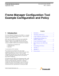
The following board map shows the board assembly from its cover side (top) and
connector side (bottom). The cover includes holes for mounting the ESMexpress
module onto a COM Express carrier.
Figure 1. Map of the board – cover side
J2
Top cover
ESMexpress connectors
(on bottom side)
1
J1
1
Screw holes to install ESMexpress module on a COM Express carrier
MEN Mikro Elektronik GmbH
20XM51-00 E3 – 2014-02-24
16
Getting Started
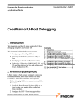
Figure 2. Map of the board – connector side
Cooling wing
Cooling wing
119
J2
61
59
119
J1
ESMexpress
connectors
Cooling wing
Cooling wing
1
Frame
61
59
1
Cooling wing
Cooling wing
Holes for mounting screws on carrier board
Screws connecting the frame and cover. Don’t remove!
MEN Mikro Elektronik GmbH
20XM51-00 E3 – 2014-02-24
17
Getting Started
1.2
First Operation
You can use the following check list when installing the board for the first time and
with minimum configuration using a Windows host PC.
The U-Boot firmware is preinstalled on the XM51 and is preconfigured for the
board.
Power-down the system.
Install the XM51 on your ESMexpress carrier board, making sure that the
ESMexpress connectors are properly aligned.
To provide a better example, we assume that you are using MEN’s standard
evaluation carrier, XC1, which provides the necessary connections for a Windows
host PC. You can find more information on the XC1 in the XC1 User Manual, which
is available for download on MEN’s website.
Install a USB-to-UART driver on your host PC.
You can use a driver provided by MEN (article number 13T005-70, third-party)
or go to the FTDI web site (www.ftdichip.com/FTDrivers.htm) and download a
driver there.
Connect a Windows PC to USB port 7 of XC1 (UART-to-USB COM interface).
To do this, you need a suitable USB cable (type A to A, included with XC1).
ETHA
ETHB
ETHC
USB0
USB2
USB6
USB1
USB3
USB7
Power-up the system.
Start up a terminal program on your Windows PC, e.g., HyperTerm, and open a
terminal connection.
Set your terminal connection to the following protocol:
-
MEN Mikro Elektronik GmbH
20XM51-00 E3 – 2014-02-24
115 200 baud data transmission rate
8 data bits
1 stop bit
No parity
18
Getting Started
U-Boot will load and then display a command line. The terminal displays a
message similar to the following:
U-Boot 2010.12 (Nov 17 2011 - 15:24:17) MEN XM51 0.0.0 alpha (64MB fallback)
CPU0: P4080, Version: 2.0, (0x82000020)
Core: E500MC, Version: 2.0, (0x80230020)
Clock Configuration:
CPU0:1200 MHz, CPU1:1200 MHz, CPU2:1200 MHz, CPU3:1200 MHz,
CPU4:1200 MHz, CPU5:1200 MHz, CPU6:1200 MHz, CPU7:1200 MHz,
CCB:600 MHz,
DDR:600 MHz (1200 MT/s data rate) (Asynchronous), LBC:37.500 MHz
FMAN1: 450 MHz
FMAN2: 450 MHz
PME:
450 MHz
L1:
D-cache 32 kB enabled
I-cache 32 kB enabled
Board: MEN XM51
Reset Configuration Word (RCW):
00000000: 4c580000 00000000 18185218 0000cccc
00000010: 389f4440 3c3c2000 fe800000 e1000000
00000020: 00000000 00000000 00000000 c0ddd0f4
00000030: a0000000 00000000 00000000 00000000
I2C:
Reset PCIe Bridge... ready
DRAM: Initializing....using SPD
(memory mapped)
Detected UDIMM
Detected UDIMM
Detected 4096 MB of memory
This U-Boot only supports < 4G of DDR
You could rebuild it with CONFIG_PHYS_64BIT
DDR: 2 GiB (DDR3, 64-bit, CL=8, ECC on)
DDR Controller Interleaving Mode: cache line
Testing 0x00000000 - 0x7fffffff
...Further test output...
Boot: os=please_set_to_vxworks_or_linux (e.g. setenv os linux;saveenv) bootmethod=tftp
Auto-update from TFTP: failed, env. variable 'updatefile' not found
Hit any key to stop autoboot: 0
XM51=>
Note: Don’t power off the XM51 now, otherwise the UART-to-USB interface on the
host PC will be disconnected.
Now you can make configurations for your operating system in the U-Boot
boot loader. See the detailed description in Chapter 3 U-Boot Boot Loader on
page 39.
MEN Mikro Elektronik GmbH
20XM51-00 E3 – 2014-02-24
19
Getting Started
1.3
Installing Operating System Software
The board supports VxWorks. A Linux BSP is available on request. U-Boot is
designed to include Linux support.
!
By default, no operating system is installed on the board. Please refer to the
respective documentation on how to configure your operating system image!
The U-Boot Chapter of this manual describes the first steps of how to get your
operating system running, see Chapter 3.2 Getting Started: Setting Up Your
Operating System on page 40.
You can find any software available in the XM51 pages on MEN’s website.
MEN Mikro Elektronik GmbH
20XM51-00 E3 – 2014-02-24
20
Functional Description
2
Functional Description
The following describes the individual functions of the board and their
configuration on the board. There is no detailed description of the individual
controller chips and the CPU. They can be obtained from the data sheets or data
books of the semiconductor manufacturer concerned (Chapter 5.1 Literature and
Web Resources on page 61).
Please note that the board BSPs for the different operating systems may not
support all the functions of the XM51. For more information on hardware support
please see the respective BSP data sheet on MEN’s website.
2.1
Power Supply
The XM51 board is supplied with +12 V (9 to 16 V) only via ESMexpress
connectors J1/J2. All other required voltages are generated on the board.
2.2
Board Supervision
2.2.1
Temperature and Voltage
The board features a temperature sensor and voltage monitor.
A voltage monitor supervises all used voltages and holds the CPU in reset condition
until all supply voltages are within their nominal values.
2.2.2
Watchdog
The board features a window watchdog that must be triggered within a window
open period of 340 ms and 8.7 s. After configuration the CPU serves the watchdog.
Other than an ordinary timeout watchdog, a window watchdog must be triggered
within a certain time window rather than just within a certain maximum time. If the
program execution hangs within a loop that includes the function triggering the
watchdog, a non-window watchdog might be triggered correctly although there was
an error and thus the erroneous situation might stay undetected. Using a window
watchdog significantly increases the operational safety.
Figure 3. Window watchdog triggering
The watchdog must be triggered within this window.
The watchdog initiates a reset if it is triggered
• earlier than 340 ms after the last valid trigger or
• later than 8.7 s after the last valid trigger.
WD Trigger
...
Watchdog window open
340 ms to 8.7 s
Watchdog enabled
Watchdog is triggered
10 s
Watchdog is triggered
Watchdog is 20 s
triggered
t
The watchdog can be enabled or disabled and can be triggered by a software
application. This function is normally supported by the board support package (see
BSP documentation).
MEN Mikro Elektronik GmbH
20XM51-00 E3 – 2014-02-24
21
Functional Description
2.3
Real-Time Clock
The board includes an RA8581 real-time clock. For data retention during power off
the RTC must be supplied with 3 V via J1 pin Vbatt (J1-55) using an external
GoldCap or battery device mounted on the carrier board.
2.4
Processor Core
The board is equipped with a multi-core Freescale QorIQ P4080, P4040 or P3041
processor up to 1.5 GHz, which includes four or eight 32-bit Power Architecture
e500mc cores, high-performance datapath acceleration logic, and network and
peripheral bus interfaces.
2.4.1
General
The QorIQ processor family can be used for combined control, datapath, and
application layer processing. Its high level of integration offers significant
performance benefits compared to multiple discrete devices, while also greatly
simplifying board design. The processor is well-suited for applications that are
highly compute-intensive, mission-critical, or both.
The P4080 and P4040 have two independent 64-bit DDR2/3 memory controllers
with ECC. All types provide advanced processing, including Datapath Acceleration
Architecture for functions like packet parsing, queue management, congestion
management or encryption. They also integrate high-speed serial interfaces, with
Gigabit Ethernet, PCI Express 2.x and SATA Revision 2.x support. The selection of
three different QorIQ-family processor types usable on the XM51 allows tailoring
of the computer-on-module for different application requirements.
Table 1. Processor core options on XM51
Processor Type
P4080
Core Frequency
DDR3 RAM
L3 Cache
Power
Consumption1
8
2 controllers,
up to 16 GB
2 MB
30 W max.
P4040
4
2 controllers,
up to 16 GB
2 MB
24 W max.
P3041
4
1 controller,
up to 8 GB
1 MB
18.2 W max.
1
1.2 GHz, 1.33 GHz
or 1.5 GHz
Cores
Only for processor. For a maximum power consumption of the entire COM board, add 2 W each.
MEN Mikro Elektronik GmbH
20XM51-00 E3 – 2014-02-24
22
Functional Description
2.4.2
Thermal Considerations
The XM51 generates an absolute maximum of 32 W of power dissipation with a
P4080 processor operated at 1.5 GHz and supports extended operating temperatures
in all configurations.
The ESMexpress module is enclosed inside a cover and frame and therefore
provides a flexible thermal interface that can be used as needed to fulfill the thermal
needs of the application. Typically you should use it for conduction cooling or
convection cooling. It depends on the system configuration and airflow if an
additional heat sink is needed or not. In any case you should check your thermal
conditions and implement appropriate cooling.
See also Chapter 2.10.2 Thermal Concept on page 27.
!
Please note that if you do not use the cover and frame supplied by MEN and/or no
heat sink, warranty on functionality and reliability of the XM51 may cease. If you
have any questions or problems regarding thermal behavior, please contact MEN.
MEN Mikro Elektronik GmbH
20XM51-00 E3 – 2014-02-24
23
Functional Description
2.5
Memory and Mass Storage
2.5.1
DRAM System Memory
The board provides up to 16 GB onboard, soldered DDR3 SDRAM with ECC
(error-correcting code) on two banks. The memory bus is 72 bits wide including
ECC and operates at up to 667 MHz (physical), depending on processor
configuration.
ECC memory provides greater data accuracy and system uptime by protecting
against soft errors in computer memory.
The P4080 and P4040 have two independent memory controllers. The two RAM
banks can be assigned to processor cores to avoid access conflicts and assure
deterministic behavior. The P3041 has only one controller (and memory bank).
Note: Currently only 2 GB are supported by U-Boot and by the VxWorks BSP.
2.5.2
FRAM
The board has up to 128 KB non-volatile FRAM memory connected to the local bus
of the CPU.
The FRAM does not need a back-up voltage for data retention.
2.5.3
NOR Flash
The board includes up to 256 MB soldered NOR Flash memory controlled by the
CPU. The data bus is 16 bits wide.
Flash memory contains the U-Boot/operating system bootstrapper and U-Boot
environment variables. It can also contain the operating system and application
software. See Chapter 3 U-Boot Boot Loader on page 39.
2.5.4
Serial ATA (SATA)
The XM51 provides two serial ATA channels through a PCIe-to-SATA converter
that is connected to the QorIQ processor via a dedicated PCIe x1 link. The SATA
channels are led to the ESMexpress connector.
The interfaces are compliant with SATA Revision 2.x and support transfer rates of
3.0 Gbits/s.
You can find the pinout for the SATA signals in Table 3, Pin assignment of
ESMexpress connector J1, pins 61..120 on page 30.
MEN Mikro Elektronik GmbH
20XM51-00 E3 – 2014-02-24
24
Functional Description
2.6
USB Interfaces
The XM51 provides four USB 2.0 host ports and one USB client port at the
ESMexpress connector.
The four host ports are controlled via a USB hub connected to the QorIQ processor
via PCI Express, while the client port is driven by a UART-to-USB converter. All
ports are implemented with EHCI/OHCI and support high-speed, fullspeed and lowspeed operation.
The UART-to-USB interface supports data rates up to 230.4 kbits/s. It has no
handshake lines. In connection with USB-to-UART driver software it can be used as
a COM interface and is supported by U-Boot as a console device.
You can find the pinout for the USB signals in Table 3, Pin assignment of
ESMexpress connector J1, pins 61..120 on page 30 and Table 4, Pin assignment of
ESMexpress connector J1, pins 1..60 on page 31.
2.7
Ethernet Interfaces
The XM51 has two Ethernet interfaces controlled by the CPU. All channels support
up to 1000 Mbits/s and full-duplex operation.
You can find the pinout for the Ethernet signals in Table 4, Pin assignment of
ESMexpress connector J1, pins 1..60 on page 31.
!
The unique MAC address is set at the factory and should not be changed. Any
attempt to change this address may create node or bus contention and thereby render
the board inoperable. The MAC addresses on XM51 are:
• ETHA:
• ETHB:
0x 00 C0 3A AE 00 00 - 0x 00 C0 3A AE 07 FF
0x 00 C0 3A AE 08 00 - 0x 00 C0 3A AE 0F FF
where "00 C0 3A" is the MEN vendor code. The last six digits are product-specific
and depend on the interface and the serial number of the product. The serial number
is added to the channel offset, for example for ETHB: "... 08 2A" for serial number
"000042". (See Chapter 5.2 Finding out the Product’s Article Number, Revision and
Serial Number on page 62.)
MEN Mikro Elektronik GmbH
20XM51-00 E3 – 2014-02-24
25
Functional Description
2.8
GPIO
The XM51 provides three GPIO pins driven by the board controller for user-defined
options or for board status LEDs. The LEDs can be made available on the carrier
board.
The GPIO pins are accessible through driver software provided by the board support
package.
The two signals defined by the ESMexpress specification as PWRBTN# and WAKE#
are implemented as GPIO pins on the XM51.
Table 2. GPIO signals to CPU pins assignment
XM51 Signal
CPU Signal
CPU Package Pin Number
GPIO/LED#
GPIO24
AG17
GPIO25 (WAKE#)
GPIO25
AM13
GPIO26 (PWRBTN#)
GPIO26
AG13
You can find the GPIO pins in Table 4, Pin assignment of ESMexpress connector J1,
pins 1..60 on page 31.
2.9
PCI Express Interface
Two PCI Express x1 links are available on the XM51. The links support PCI
Express 2.x with a data rate of 500 MB/s in each direction and a bandwidth of
5 Gbits/s per lane.
The interfaces are numbered A0 and A1 and can be accessed on the ESMexpress
connector.
You can find the pinout for the PCI Express signals in Table 3, Pin assignment of
ESMexpress connector J1, pins 61..120 on page 30 and Table 6, Pin assignment of
ESMexpress connector J2, pins 1..60 on page 33.
MEN Mikro Elektronik GmbH
20XM51-00 E3 – 2014-02-24
26
Functional Description
2.10
ESMexpress
ESMexpress is a Computer-On-Module (COM/SOM) standard that is especially
ruggedized and provides a high-performance, low-power architecture for harsh
environments.
The ESMexpress concept has been developed for applications that require highly
robust electronics to ensure safe and reliable operation even in severe environments,
e.g., in railways and avionics, industrial automation and medical engineering or
mobile applications in general.
Together with an application-specific carrier board, it forms a semi-custom solution
for industrial, harsh, mobile and mission-critical environments.
2.10.1
Mechanical Concept
ESMexpress modules are embedded in a frame and a cover, and are firmly screwed
to a carrier board. The frame and the cover ensure 100% EMC protection. Only
soldered components are used to withstand shock and vibration, and the design is
optimized for conformal coating. All ESMexpress modules support a single
95 x 125 mm form factor.
2.10.2
Thermal Concept
ESMexpress modules are equipped with eight cooling wings for conductive cooling.
The heat generated on the board is transported to the frame and the cover via the
cooling wings. The frame and the cover, however, are only part of the thermal
solution for a module. They only provide a common interface between the
ESMexpress module and implementation-specific thermal solutions.
The module can e.g. be cooled via conductive cooling, where the heat is transported
to a housing or a heat sink built on top of the cover. Where operating temperatures
are moderate, the module may even do without the frame and cover, with a suitable
low-power processor and airflow.
MEN Mikro Elektronik GmbH
20XM51-00 E3 – 2014-02-24
27
Functional Description
Figure 4. ESMexpress thermal concept: cooling wings between frame and cover
Cooling wing
Cooling wing
119
J2
61
59
119
J1
ESMexpress
connectors
Cooling wing
Cooling wing
1
Frame
61
59
1
Cooling wing
Cooling wing
Holes for mounting screws on carrier board
Screws connecting the frame and cover. Don’t remove!
Please contact MEN’s sales team for further information.
MEN Mikro Elektronik GmbH
20XM51-00 E3 – 2014-02-24
28
Functional Description
2.10.3
ESMexpress Connectors
The XM51 is connected to the carrier board via two 120-pin connectors.
Connector types:
• 2-row, 120-pin high-speed receptacle, 0.5mm pitch, e.g. Samtec QSH-060-01-L-D-A-K
• Mating connector:
2-row, 120-pin high-speed plug connector, 0.5mm pitch
!
Note: In the following pinout tables the ESMexpress connectors are shown as if seen through the cover side
and PCB, i.e. the pin layout (position of pin 1) will
be the same on a carrier board.
J2
Cf. Figure 1, Map of the board – cover side (page 16)
and Figure 2, Map of the board – connector side
(page 17).
ESMexpress connectors
(on bottom side)
1
J1
1
MEN Mikro Elektronik GmbH
20XM51-00 E3 – 2014-02-24
29
Functional Description
Table 3. Pin assignment of ESMexpress connector J1, pins 61..120
119
61
62
59
60
MEN Mikro Elektronik GmbH
20XM51-00 E3 – 2014-02-24
120
119
PCIE_A0_TX+
120
PCIE_A0_RX+
117
PCIE_A0_TX-
118
PCIE_A0_RX-
115 CLK_REQ_CLK_A0_REF#
116
GND
113
PCIE_CLK_A0_REF+
114
-
111
PCIE_CLK_A0_REF-
112
-
109
-
110
-
107
-
108
-
105
-
106
-
103
-
104
-
101
-
102
-
99
-
100
-
97
GND
98
GND
95
SATA0_TX+
96
SATA0_RX+
93
SATA0_TX-
94
SATA0_RX-
91
GND
92
GND
89
SATA1_TX+
90
SATA1_RX+
87
SATA1_TX-
88
SATA1_RX-
85
GND
86
GND
83
-
84
-
81
-
82
-
79
GND
80
GND
77
USB0+
78
USB1+
75
USB0-
76
USB1-
73
USB_OC_0_1#
74
USB_OC_2_3#
71
USB2+
72
USB3+
69
USB2-
70
USB3-
67
GND
68
GND
65
-
66
-
63
-
64
-
61
-
62
-
GND
30
Functional Description
Table 4. Pin assignment of ESMexpress connector J1, pins 1..60
61
62
59
60
1
MEN Mikro Elektronik GmbH
20XM51-00 E3 – 2014-02-24
2
59
-
60
USB7+ / UART TX
57
-
58
USB7- / UART RX
55
Vbatt
56
-
53
PWR_OK
54
PS_ON#
51
I2C_DATA
52
RESET_IN#
49
I2C_CLK
50
RESET_OUT#
47
-
48
GPIO25 (WAKE#)
45
GPIO/LED#
46
GPIO26 (PWRBTN#)
43
-
44
-
41
-
42
-
39
-
40
-
37
-
38
-
35
-
36
-
33
-
34
-
31
-
32
-
29
-
30
-
27
-
28
-
25
-
26
GND
23
ETH_B_LED_LINK#
24
ETH_B_LED_ACT#
21
ETH_B0+
22
ETH_B1+
19
ETH_B0-
20
ETH_B1-
17
ETH_B2+
18
ETH_B3+
15
ETH_B2-
16
ETH_B3-
13
ETH_B_REF
14
GND
11
ETH_A_LED_LINK#
12
ETH_A_LED_ACT#
9
ETH_A0+
10
ETH_A1+
7
ETH_A0-
8
ETH_A1-
5
ETH_A2+
6
ETH_A3+
3
ETH_A2-
4
ETH_A3-
1
ETH_A_REF
2
GND
+12V
31
Functional Description
Table 5. Pin assignment of ESMexpress connector J2, pins 61..120
119
61
62
59
60
MEN Mikro Elektronik GmbH
20XM51-00 E3 – 2014-02-24
120
119
-
120
-
117
-
118
-
115
GND
116
GND
113
-
114
-
111
-
112
-
109
GND
110
GND
107
-
108
-
105
-
106
-
103
GND
104
GND
101
-
102
-
99
-
100
-
97
GND
98
GND
95
-
96
-
93
-
94
-
91
GND
92
GND
89
-
90
-
87
-
88
-
85
GND
86
GND
83
-
84
-
81
-
82
-
79
GND
80
GND
77
-
78
-
75
-
76
-
73
GND
74
GND
71
-
72
-
69
-
70
-
67
GND
68
GND
65
-
66
-
63
-
64
-
61
-
62
-
GND
32
Functional Description
Table 6. Pin assignment of ESMexpress connector J2, pins 1..60
61
62
59
60
1
MEN Mikro Elektronik GmbH
20XM51-00 E3 – 2014-02-24
2
59
-
60
-
57
-
58
-
55
-
56
-
53
GND
54
GND
51
-
52
-
49
-
50
-
47
GND
48
GND
45
-
46
-
43
-
44
-
41
GND
42
GND
39
-
40
-
37
-
38
-
35
GND
36
GND
33
-
34
-
31
-
32
-
29
GND
30
GND
27
-
28
-
25
-
26
-
23
GND
24
GND
21
PCIE_CLK_A1_REF+
22
-
19
PCIE_CLK_A1_REF-
20
-
17 CLK_REQ_CLK_A1_REF#
18
GND
15
-
16
-
13
-
14
-
11
GND
12
GND
9
-
10
-
7
-
8
-
5
GND
6
GND
3
PCIE_A1_TX+
4
PCIE_A1_RX+
1
PCIE_A1_TX-
2
PCIE_A1_RX-
GND
33
Functional Description
Table 7. Signal mnemonics of 120-pin ESMexpress connectors
Signal
Power
SATA
USB
Function
GND
-
Ground
Vbatt
in
3V battery voltage
out
Enable signal for external power supply
in
Power OK signal from external power supply
RESET_IN#
in
Reset signal from carrier board
RESET_OUT#
out
Reset signal from CPU board
Power
PS_ON#
Management PWR_OK
PCI Express
Direction
CLK_REQ_CLK_A[0:1]_REF# in
100 MHz Clock request signals
PCIE_A[0:1]_RX+,
PCIE_A[0:1]_RX-
in
Differential PCIe receive lines, x1 links A0
and A1
PCIE_A[0:1]_TX+,
PCIE_A[0:1]_TX-
out
Differential PCIe transmit lines, x1 links A0
and A1
PCIE_CLK_A[0:1]_REF+,
PCIE_CLK_A[0:1]_REF-
out
Reference clocks A0/A1 100 MHz
SATA0_RX+, SATA0_RX-
in
Differential SATA receive lines, port 0
SATA0_TX+, SATA0_TX-
out
Differential SATA transmit lines, port 0
SATA1_RX+, SATA1_RX-
in
Differential SATA receive lines, port 1
SATA1_TX+, SATA1_TX-
out
Differential SATA transmit lines, port 1
USB0+, USB0-
in/out
Differential USB lines, port 0
USB1+, USB1-
in/out
Differential USB lines, port 1
USB2+, USB2-
in/out
Differential USB lines, port 2
USB3+, USB3-
in/out
Differential USB lines, port 3
USB7+, USB7-
in/out
Differential UART-to-USB lines (USB port 7)
(USB7+ corresponds to UART TX,
USB7- corresponds to UART RX)
USB_OC_0_1#
in
USB overcurrent, ports 0 and 1
USB_OC_2_3#
in
USB overcurrent, ports 2 and 3
MEN Mikro Elektronik GmbH
20XM51-00 E3 – 2014-02-24
34
Functional Description
Signal
Ethernet
Other
Direction
Function
ETH_A_LED_ACT#
out
Signal for activity status LED, port A
ETH_A_LED_LINK#
out
Signal for link status LED, port A
ETH_A0+, ETH_A0-
in/out
Media Dependent Interface [0] data,
differential pair, port A
ETH_A1+, ETH_A1-
in/out
Media Dependent Interface [1] data,
differential pair, port A
ETH_A2+, ETH_A2-
in/out
Media Dependent Interface [2] data,
differential pair, port A
ETH_A3+, ETH_A3-
in/out
Media Dependent Interface [3] data,
differential pair, port A
ETH_A_REF
out
Port A reference voltage
ETH_B_LED_ACT#
out
Signal for activity status LED, port B
ETH_B_LED_LINK#
out
Signal for link status LED, port B
ETH_B0+, ETH_B0-
in/out
Media Dependent Interface [0] data,
differential pair, port B
ETH_B1+, ETH_B1-
in/out
Media Dependent Interface [1] data,
differential pair, port B
ETH_B2+, ETH_B2-
in/out
Media Dependent Interface [2] data,
differential pair, port B
ETH_B3+, ETH_B3-
in/out
Media Dependent Interface [3] data,
differential pair, port B
ETH_B_REF
out
Port B reference voltage
I2C_CLK
in/out
I2C clock
I2C_DATA
in/out
I2C data
GPIO/LED#
in/out
User-defined GPIO/LED (GPIO24 of CPU,
CPU pin AG17)
GPIO25 (WAKE#)
in/out
Defined by ESMexpress specification as PCI
Express Wake Event, but on XM51
implemented and usable as a GPIO line
(GPIO25 of CPU, CPU package pin number
AM13)
GPIO26 (PWRBTN#)
in/out
Defined by ESMexpress specification as
Power Button, but on XM51 implemented
and usable as a GPIO line (GPIO26 of CPU,
CPU package pin number AG13)
MEN Mikro Elektronik GmbH
20XM51-00 E3 – 2014-02-24
35
Functional Description
2.10.4
Using an ESMexpress Module on a COM Express
Carrier Board
The AE12 adapter card offers the possibility to evaluate an ESMexpress module on
a COM Express carrier board. It complies with the COM Express Type 2 basic form
factor.
On its top side the AE12 has ESMexpress connectors for connecting the
ESMexpress module. On the bottom side the AE12 card is equipped with standard
COM Express connectors for plugging it onto the COM Express carrier.
Figure 5. AE12 COM Express adapter board – Map of the board
ESMexpress Connectors
COM Express Connectors (on bottom side of board)
The pin assignment of the COM Express connectors is compliant to the COM
Express standard.
The pin assignment of the ESMexpress connectors is compliant to the ESMexpress
standard.
MEN Mikro Elektronik GmbH
20XM51-00 E3 – 2014-02-24
36
Functional Description
Installing the ESMexpress Module on a COM Express Carrier
Align the ESMexpress connectors and the mounting holes of the adapter and
the module and plug the AE12 adapter firmly onto the ESMexpress module.
Install the ESMexpress module on the adapter using the following mounting
holes and the seven M2x4 cross-recess pan-head screws included in the
delivery of the adapter:
ESMexpress Connectors
(on top side of board)
COM Express Connectors MEN Mikro Elektronik GmbH
20XM51-00 E3 – 2014-02-24
37
Functional Description
Turn the module around and insert five 2.5x18 cross-recess countersink-head
screws (also included in the delivery) into the five COM Express mounting
holes on the top of the ESMexpress module.
J2
Top cover
ESMexpress connectors
(on bottom side)
1
J1
1
Install the five 2.5x5 standoffs on the bottom of the adapter.
Plug the ESMexpress module/AE12 assembly onto the COM Express carrier
board.
Screw the adapter onto the COM Express carrier board using five M2.5x4
screws.
ESMexpress module
Standoff
AE12 adapter board
COM Express carrier
MEN Mikro Elektronik GmbH
20XM51-00 E3 – 2014-02-24
38
U-Boot Boot Loader
3
U-Boot Boot Loader
3.1
General
U-Boot is the CPU board firmware that is invoked when the system is powered on.
The basic tasks of U-Boot are:
•
•
•
•
Initialize the CPU and its peripherals.
PCI configuration.
Provide debug/diagnostic features on the U-Boot command line.
Boot operating system via Flash, TFTP or similar methods.
U-Boot for XM51 consists of the standard U-Boot code and a board-specific patch.
The current patch file and the complete binaries (prebuilt main U-Boot image) are
available for download on MEN’s website.
Note: U-Boot for XM51 was already designed to support both VxWorks (BSP
available) and Linux (BSP on request). Therefore, Linux was also considered
in the following description of U-Boot.
The following description only includes board-specific features. For a general
description and in-depth details on U-Boot, please refer to the DENX U-Boot and
Linux Guide (DULG) available under www.denx.de/wiki/DULG/WebHome. (For a
PDF version refer to Chapter 2.3 Availability.)
For advanced developing and programming, you can also use the following
resources:
• U-Boot source code on the DENX website (also includes README files):
http://git.denx.de (GIT repositories) and
ftp://ftp.denx.de/pub/u-boot (TAR archives)
• U-Boot mailing list: http://lists.denx.de/mailman/listinfo/u-boot
MEN Mikro Elektronik GmbH
20XM51-00 E3 – 2014-02-24
39
U-Boot Boot Loader
3.2
Getting Started: Setting Up Your Operating System
This chapter describes a recommended procedure of how to get your operating
system running for the first time, using MEN’s XC1 evaluation carrier board.
When U-Boot starts up for the first time, it does not know yet which operating
system (OS) to load and normally stops the boot procedure by its prompt. (If you
don’t see the U-Boot prompt, reset the board again and press any key during startup.) You need to make the necessary settings first and then load a boot image, e.g.,
via network.
The following gives an example of how to integrate and boot the example images
for Linux or VxWorks provided by the MEN BSPs. In the example, the images are
loaded from a host computer via TFTP.
Note: This procedure uses the U-Boot standard commands to make the individual
steps clearer. For your actual application, you can use additional environment
variables that the XM51 U-Boot provides for booting, and which short-cut the
individual steps shown below. See Chapter 3.4.1 Booting an Operating System on page 45.
Connect the host computer where your boot image is located to the XM51’s
ETHA Ethernet port.
3.2.1
Setting Up the Boot File
Create a boot file for your operating system on your host computer.
3.2.2
Setting Up the Boot and TFTP Parameters
Set the network parameters through the U-Boot environment variables for the
network connection:
XM51=> editenv ipaddr
Edit IP address and press <Enter>
edit: 192.1.1.120
XM51=> editenv serverip
Edit TFTP server IP address and press <Enter>
edit: 192.1.1.22
XM51=> editenv gatewayip
Edit IP address of the gateway and press <Enter>
edit: 192.1.1.22
XM51=> editenv netmask
edit: 255.255.255.0 Edit the subnet mask and press <Enter>
Set up the boot file through environment variable bootfile, e.g.:
Linux:
XM51=> setenv bootfile /tftpboot/pMulti_XM51
VxWorks:
XM51=> setenv bootfile /tftpboot/vxW_XM51.st
Set the boot arguments through environment variable bootargs, e.g.:
Linux:
XM51=> setenv bootargs root=/dev/ram rw
VxWorks:
XM51=> setenv bootargs dtsec(0,0)xm51:${bootfile} e=$
{ipaddr} h=${serverip} g=${gatewayip} u=username pw=password tn= s=
’u’ is the FTP user name
’pw’ is the FTP password
MEN Mikro Elektronik GmbH
20XM51-00 E3 – 2014-02-24
40
U-Boot Boot Loader
Set up the autostart script through environment variable bootcmd:
Linux:
XM51=> setenv bootcmd 'tftpboot && bootm'
VxWorks:
XM51=> setenv bootcmd 'tftpboot && cpenv && bootvx'
3.2.3
Starting Up the Operating System
Save the changed environment variables.
XM51=> saveenv
Reset the board.
XM51=> reset
U-Boot restarts the board and loads the configured operating system with the
settings made.
MEN Mikro Elektronik GmbH
20XM51-00 E3 – 2014-02-24
41
U-Boot Boot Loader
3.3
Interacting with U-Boot
U-Boot uses a shell similar to the Linux Hush shell with a command history and
autocompletion support.
3.3.1
Setting Up a Console Connection
To interact with U-Boot, you can use the UART-to-USB interface (UART COM1) as
a serial console port in RS232 mode. (See Chapter 2.6 USB Interfaces on page 25.)
You can select the active console by means of environment variables stdin, stdout
and stderr, see Table 11, U-Boot – Environment variables – Console on page 55.
U-Boot command coninfo lists all active consoles.
The default setting of the COM ports is 115200 baud, 8 data bits, no parity, and one
stop bit. (You can set the baud rate through environment variable baudrate, see
description on page 55.)
3.3.2
Entering the U-Boot Command Line
During normal boot, you can abort the booting process by pressing any key during
start-up.
By default, autoboot waits 3 seconds (measured from its beginning) before it starts
the operating system, to give the user a chance to abort booting and enter the
command line.
You can modify the autoboot wait time through U-Boot environment variable
bootdelay (see Table 9, U-Boot – Environment variables – OS boot on page 53).
3.3.3
User Interface Basics
3.3.3.1
Help and Navigation
Use the help command to get a list of available commands.
Arrow keys "up" and "down" let you navigate in the command line history.
The <TAB> key autocompletes commands and variables.
You can press <CTRL> <c> to abort.
3.3.3.2
Configuring Your System
Use environment variables to configure your system. They can be viewed using the
printenv command. To set or add variables, you can use commands editenv and
setenv. To save the changed parameters use saveenv. Using command defenv the
environment variables can be reset to default values.
MEN Mikro Elektronik GmbH
20XM51-00 E3 – 2014-02-24
42
U-Boot Boot Loader
Examples: Displaying environment variables
XM51=> printenv baudrate
baudrate=115200
XM51=> printenv
baudrate=115200
bootdelay=3
...
Print all variables
XM51=> echo "Server IP: ${serverip}"
Server IP: 192.1.1.22
Shell variable expansion
Examples: Editing and saving environment variables
XM51=> editenv ipaddr
Edit the variable in the edit line and press <Enter>
edit: 192.1.1.023
XM51=> setenv ipaddr 192.1.1.123
XM51=> setenv ipaddr
XM51=> defenv
Edit a variable directly
Deletes a variable completely
Set all variables to default
You need to save the changes made, otherwise they will be lost after next reset:
XM51=> saveenv
Saving Environment to Flash...
For a list of the XM51 environment variables see Chapter 3.7.2 Environment
Variables on page 53.
3.3.3.3
Working with Scripts and Applications
You can use scripts or stand-alone applications for more complex tasks. Scripts can
be stored in environment variables and executed by the run command.
You can enter a sequence of commands using different separators:
• ; separated = all commands are executed
• && separated = next command is executed only if no error occurred
• || separated = next command is executed only if an error occurred
Simple Scripts using the Command Line
You can create a script using the command line, and you can store it in an
environment variable:
Create script (i.e. store list of commands in variable) (see also www.denx.de/
wiki/view/DULG/CommandLineParsing):
XM51=> setenv menu_script 'echo ”1=VxWorks”; echo ”2=Linux”; echo
”3=Mem test”; askenv _number; if test ${_number} = 1; then run
vxworks; elif test ${_number} = 2; then run linux; else mtest; fi'
Save the script in an environment variable (optional):
XM51=> saveenv
Execute the script:
XM51=> run menu_script
MEN Mikro Elektronik GmbH
20XM51-00 E3 – 2014-02-24
43
U-Boot Boot Loader
Scripts using Source Files
For more complex scripts, you can write a text file on your host computer, convert it,
load it into the XM51 Flash and run it on the board from the source file. The
following shows how an example script is created on a Linux host computer:
Write the script as a TXT file. In the example, we have written a file called
brd_info.txt:
# example U-Boot script (show board info)
#
# convert:
# mkimage -A ppc -O linux -T script -C none -a 0 -e 0 -n "board info
script" -d ./brd_info.txt ./brd_info.scr
echo
echo Version:
echo -------- \\c
# \\c = no new line
version
echo
echo Board:
echo ------ \\c
eeprod
echo
clocks
echo
echo Network:
echo -------echo Interface: ${ethact}
echo Target: ${ipaddr} (${ethaddr})
echo Server: ${serverip}
echo
echo bdinfo:
echo -------bdinfo
echo
Convert the TXT script to .scr format:
me@server:/> mkimage -A ppc -O linux -T script -C none -a 0 -e 0 -n
"board info script" -d /examples/brd_info.txt /tftpboot/
brd_info.scr
Download the script via network using the U-Boot command line:
XM51=> tftpboot 192.1.1.22:/tftpboot/brd_info.scr
Execute the script:
XM51=> source ${loadaddr}
MEN Mikro Elektronik GmbH
20XM51-00 E3 – 2014-02-24
44
U-Boot Boot Loader
3.4
U-Boot Image and Start-Up
U-Boot only has a main image for normal operation. The main image is stored in
the onboard boot Flash. U-Boot for XM51 has no fallback image.
After a board reset, the CPU starts executing the main image. This makes for a very
fast start-up.
To update U-Boot, you can use "run update_fb".
3.4.1
Booting an Operating System
U-Boot provides the bootm and bootvx commands to support booting of Linux and
VxWorks.
You can completely configure how U-Boot boots the operating system through
environment variables. Variables bootargs and bootcmd include the arguments to be
set and commands to be executed at boot-up to start the operating system. (See
examples in Chapter 3.2.2 Setting Up the Boot and TFTP Parameters on page 40.)
3.4.1.1
Boot Methods
Note: Please note that booting via SATA is not supported.
Note: Please remember to save the settings you have made in the environment variables using saveenv.
OS Boot via Network
U-Boot command tftpboot allows loading of the operating system via the board’s
Ethernet interface using the TFTP protocol. You can find a detailed description of
the necessary settings in Chapter 3.2.2 Setting Up the Boot and TFTP Parameters on
page 40.
OS Boot via Boot Flash
U-Boot maps Flash memory directly into the CPU memory space to make it
possible to load an operating system binary stored in the onboard boot Flash.
Set the boot arguments through environment variable bootargs, e.g.:
Linux:
XM51=> setenv bootargs root=/dev/ram rw
VxWorks:
XM51=> setenv bootargs dtsec(0,0)xm51:${bootfile} e=$
{ipaddr} h=${serverip} g=${gatewayip} u=username pw=password tn= s=
’u’ is the FTP user name
’pw’ is the FTP password
Set up the autostart script through environment variable bootcmd:
Linux:
XM51=> setenv bootcmd 'bootm 0xec020000'
VxWorks:
XM51=> setenv bootcmd 'cpenv && bootvx 0xec020000'
MEN Mikro Elektronik GmbH
20XM51-00 E3 – 2014-02-24
45
U-Boot Boot Loader
OS Boot via USB
U-Boot commands ext2load, fatload, reiserload or usbboot (raw) allow loading of
the operating system via USB mass storage devices connected to the onboard PCI
USB controller, i.e. USB ports USB0 to USB3. The command to be used depends
on the file system of the USB device. (See also Chapter 3.6.2 USB on page 51.)
Example with fatload:
Set the load address to the default DRAM value in environment variable loadaddr:
XM51=> setenv loadaddr 0x02000000
Set up the boot file through environment variable bootfile, e.g.:
Linux:
XM51=> setenv bootfile /pMulti_XM51
VxWorks:
XM51=> setenv bootfile /vxW_XM51.st
Set the boot arguments through environment variable bootargs, e.g.:
Linux:
XM51=> setenv bootargs root=/dev/ram rw
VxWorks:
XM51=> setenv bootargs dtsec(0,0)xm51:${bootfile} e=$
{ipaddr} h=${serverip} g=${gatewayip} u=username pw=password tn= s=
’u’ is the FTP user name
’pw’ is the FTP password
Set up the autostart script through environment variable bootcmd to initialize
the USB device and load the boot file into DRAM:
Linux:
XM51=> setenv bootcmd 'usb start; fatload usb 0:1 ${loadaddr}
0:1 = device 0 partition 1
${bootfile}; bootm'
VxWorks:
XM51=> setenv bootcmd 'usb start; fatload usb 0:1 ${loadaddr}
0:1 = device 0 partition 1
${bootfile}; cpenv && bootvx'
MEN Mikro Elektronik GmbH
20XM51-00 E3 – 2014-02-24
46
U-Boot Boot Loader
3.4.1.2
Configuring Boot using Additional Environment
Variables
Due to additional environment variables provided by the XM51 U-Boot, it takes
only a few steps to configure booting:
Set the operating system to linux or vxworks through environment variable os:
XM51=> setenv os linux
Set the boot method to flash, tftp or usb through environment variable
bootmethod:
XM51=> setenv bootmethod tftp
Set the boot files:
Linux:
XM51=> editenv linux_file
VxWorks:
XM51=> editenv vxworks_file
Set the boot arguments (the defaults should work in most cases):
Linux:
XM51=> editenv linux_setargs
VxWorks:
XM51=> editenv vxworks_setargs
For VxWorks: If you want to boot a VxWorks SMP image (to use all 8 CPU
cores) you need to set mp_holdoff to yes:
XM51=> setenv mp_holdoff yes
Set environment variable bootcmd:
XM51=> setenv bootcmd 'run ${os}'
If you want to start the boot directly from U-Boot, execute:
Linux:
XM51=> run linux
VxWorks:
XM51=> run vxworks
MEN Mikro Elektronik GmbH
20XM51-00 E3 – 2014-02-24
47
U-Boot Boot Loader
3.5
Updating the Boot Flash
You can update U-Boot and other binaries located in the boot Flash via a serial
console connection, network or USB device.
The XM51 U-Boot supports hardware protection.
3.5.1
Update via the Serial Console
U-Boot provides the loady, protect, erase and cp commands to download a binary
update file and program the boot Flash.
The terminal emulation program must be configured to start the upload via the
"Ymodem" (for loady) or "Kermit" protocol (for loadb and loads) and send the
required file.
3.5.2
Update via Network
You can use U-Boot commands tftpboot, protect, erase and cp to download the
binary update file from a TFTP server in the network and program the boot Flash.
3.5.3
Update via USB
You can also make a Flash update from a USB device, e.g., a USB Flash drive. Use
the U-Boot ext2load, fatload, reiserload or usbboot (raw) command.
3.5.4
Performing an Update
To perform an update, e.g., of your operating system image inside the Flash, use the
following procedure.
For instructions on how to update the U-Boot code itself, please see Chapter
3.5.5 Updating U-Boot Code on page 50.
For a memory map of the Flash, please see Chapter 3.7.1 Boot Flash Memory
Map on page 53.
Download the update file:
Via serial console, e.g., with Y protocol:
XM51=> loady
Via network, e.g.:
XM51=> tftpboot 192.1.1.22:/path/file.bin
Via USB storage, e.g.:
XM51=> usb start; fatload usb 0:1 ${loadaddr} /file.bin
0:1 = device 0 partition 1
Unprotect the Flash (i.e. unlock Flash sector protection):
XM51=> protect off 0xec020000 +${filesize}
0xec020000 is the update address
Erase the part of the Flash that you want to update:
XM51=> erase 0xec020000 +${filesize}
MEN Mikro Elektronik GmbH
20XM51-00 E3 – 2014-02-24
48
U-Boot Boot Loader
Write the file to Flash:
XM51=> cp.b ${loadaddr} 0xec020000 ${filesize}
Protect the Flash again:
XM51=> protect on all
If you want to do your updates in a more user-friendly way, you can create a script
that includes the above steps:
Create a new update script in an environment variable, e.g.:
XM51=> setenv update_os 'setenv bootfile /tftpboot/pMulti_XM51 &&
editenv bootfile && setenv loadaddr 02000000 && tftpboot && itest
${filesize} != 0 && protect off ec020000 efdfffff && erase ec020000
+${filesize} && cp.b ${loadaddr} ec020000 $ {filesize}; protect on
all'
Save the script (optional):
XM51=> saveenv
Start the update:
XM51=> run update_os
MEN Mikro Elektronik GmbH
20XM51-00 E3 – 2014-02-24
49
U-Boot Boot Loader
3.5.5
Updating U-Boot Code
Updates of the XM51 U-Boot (only main image) are available for download from
MEN’s website. U-Boot’s integrated Flash update functions allow you to do updates
yourself. However, you need to take care and follow the instructions given here.
Otherwise, you may make your board inoperable!
!
In any case, read the following instructions carefully!
Please be aware that you do U-Boot updates at your own risk. After an
incorrect update your CPU board may not be able to boot.
Do the following to update U-Boot:
Unzip the downloaded file, e.g., 14XM51-00_01_02.zip, into a temporary
directory.
Connect a terminal emulation program with the UART-to-USB interface
(UART COM1) of your XM51 and set the terminal emulation program to
115200 baud, 8 data bits, 1 stop bit, no parity, no handshaking (if you haven't
changed the target baud rate before).
Power on your XM51 and press "ENTER" immediately.
In your terminal emulation program, you should see the U-Boot prompt.
XM51=>
Enter run update:
XM51=> run update
!
Note: Please note that the current U-Boot implementation only supports the
fallback image. To update U-Boot, please use run update_fb.
U-Boot asks you by which means you want to do the update. Type in uart and
<ENTER>.
Please enter 'tftp,bootp or uart':uart
via UART:
## Ready for binary (ymodem) download to 0x02000000 at 115200 bps...
C(CAN) packets, 3 retries
## Total Size
= 0x00061a1c = 399900 Bytes
....... done
Un-Protected 7 sectors
.... done
Erased 4 sectors
Copy to Flash... done
Protect Flash Bank # 1
...................................................................
..........................e
XM51=>
In your terminal emulation program, start a "YModem" download of the image
file, e.g., u-boot_XM51_1.0.bin. For example, with Windows Hyperterm, select
Transfer > Send File with protocol "YModem".
As the last step after the download, the Flash is programmed. When the update
procedure has completed, reset the XM51.
MEN Mikro Elektronik GmbH
20XM51-00 E3 – 2014-02-24
50
U-Boot Boot Loader
3.6
Accessing Devices
U-Boot provides some useful commands especially for PCI, USB and I2C devices.
For a complete list of available U-Boot commands, see Chapter 3.8 U-Boot
Commands on page 56.
3.6.1
PCI
List PCI devices
pci [bus] [long]
List of PCI devices on bus bus (long = detailed)
Read (config space)
pci display[.b,.w,.l] b.d.f [addr] Read config space
[no_of_objects]
pci header b.d.f
Show header of PCI device 'bus.device.function'
Write (config space)
pci write[.b,.w,.l] b.d.f addr value Write to config space
pci modify[.b,.w,.l] b.d.f addr
Modify config space (read, write)
pci next[.b,.w,.l] b.d.f addr
Modify config space (const. addr.)
3.6.2
USB
Before you access USB devices you have to call usb start. At compilation time, a
specific USB controller must be configured, e.g., the EHCI (high-speed) onboard
PCI/USB controller. This means that high-speed and low/full-speed devices cannot
be supported at the same time.
List all devices
usb tree
Show USB device tree
usb info [dev]
Show available USB devices
List storage devices
usb storage
Show details of USB storage devices
usb part [dev]
Print partition table of one or all USB storage
devices
Read RAW data
usb dev [dev]
Show or set current USB storage device
usb read addr blk# cnt
Read cnt blocks starting at block blk# to
memory address addr
MEN Mikro Elektronik GmbH
20XM51-00 E3 – 2014-02-24
51
U-Boot Boot Loader
Read file system
Use commands ext2load, ext2ls, fatinfo, fatload, fatls, reiserload or reiserls, e.g.:
XM51=> fatinfo usb 0:1
0:1 = device 0 partition 1
XM51=> fatls usb 0:1
use usb part to find dev/part
XM51=> fatload usb 0:1 ${loadaddr} /path/file
3.6.3
I2C
Set bus
i2c dev [dev]
Show or set current I2C bus
List
i2c probe
Show devices on the I2C bus
Read
i2c md chip addr[.0, .1, .2]
[no_of_objects]
Read from I2C device
i2c loop chip addr[.0, .1, .2]
[no_of_objects]
Loop reading of device
Write
i2c mm chip addr[.0, .1, .2]
Write (modify)
i2c mw chip addr[.0, .1, .2] value Write (fill)
[count]
i2c nm chip addr[.0, .1, .2]
MEN Mikro Elektronik GmbH
20XM51-00 E3 – 2014-02-24
Write (constant addr.)
52
U-Boot Boot Loader
3.7
U-Boot Configuration and Organization
3.7.1
Boot Flash Memory Map
Table 8. U-Boot – Boot Flash memory map
CPU Address Space
0x Ex00 0000..Ex01
1
Size
FFFF1
Description
128 KB
0x Ex00 0000: Reset Configuration Word &
Pre-Boot
0x Ex00 3000: SPD data for DDR SDRAM
0x Ex00 4000: P3041 Microcode
0x Ex02 0000..EFDF FFFF1
Flash size 2176 KB
Available to user
0x EFE0 0000..EFE1 FFFF
128 KB
Reserved for MEN production data or redundant
U-Boot environment
0x EFE2 0000..EFEF FFFF
896 KB
U-Boot binary
0x EFF0 0000..EFF1 FFFF
128 KB
U-Boot Parameter Section
0x EFF2 0000..EFFF FFFF
896 KB
U-Boot binary (fallback)
The base address differs depending on the Flash size:
64 MB Flash: x = 0xC
128 MB Flash: x = 0x8
256 MB Flash: x = 0x0
3.7.2
Environment Variables
U-Boot uses environment variables to configure the target. The available variables
are board-specific for the XM51.
Environment variables are stored in Flash. They can be viewed using the printenv
command. To set or add variables, you can use commands editenv and setenv. To
save the changed parameters use saveenv. See Chapter 3.3.3.2 Configuring Your
System on page 42 for command line examples.
Table 9. U-Boot – Environment variables – OS boot
Variable
Description
Default
bootargs
Boot arguments when booting an OS image
The boot command will
set bootargs.
r/w
bootcmd
Command string that is automatically
executed after reset
run ${os}
r/w
bootdelay
Delay before the default image is
automatically booted. Set to -1 to disable
autoboot
3
r/w
bootmethod1
Method to boot operating system
Possible values: bootp, flash, tftp, usb
tftp
r/w
linux_file1
Linux boot file used by default bootcmd
/tftpboot/pMulti_XM51
r/w
linux_setargs1
Used to set bootargs
Default:
setenv bootargs root=/dev/ram rw console=ttyS0,${baudrate}
MEN Mikro Elektronik GmbH
20XM51-00 E3 – 2014-02-24
Access
r/w
53
U-Boot Boot Loader
Variable
1
Description
Default
Access
linux1
Example script for booting Linux
Default:
setenv bootfile ${linux_file};setenv loadaddr 02000000;run
linux_setargs ${bootmethod};bootm ${loadaddr}
r/w
os1
Operating system to boot (e.g., vxworks,
linux)
--- do not boot ---
r/w
vxworks_file1
VxWorks boot file used by default bootcmd
/tftpboot/vxW_XM51.st
r/w
vxworks_setargs1
Used to set bootargs
Default:
setenv bootargs dtsec(0,0)${hostname}:${bootfile} e=${ipaddr}
h=${serverip} g=${gatewayip} u=${user} pw=${pwd} tn=${target}
s=${script}
r/w
vxworks1
Example script for booting VxWorks
Default:
${vxworks_file};setenv loadaddr 02000000;run vxworks_setargs
${bootmethod};cpenv;bootvx ${loadaddr}
r/w
These MEN-specific variables can be used to provide a user-friendly way to boot the operating system: Once
files and arguments are set correctly, the user can boot the operating system using commands boot, run linux or
run vxworks.
Table 10. U-Boot – Environment variables – Network
Variable
Description
Default
Access
bootfile
Name of the image to load through command
tftpboot
Empty
r/w
ethact
Controls which network interface is currently
active
FM1@DTSEC1
r/w
ethaddr
eth1addr
MAC addresses of first Ethernet interface
(FM1@DTSEC1) and second Ethernet
interface (FM1@DTSEC2) determined at
start-up (see Chapter 2.7 Ethernet Interfaces
on page 25). You can pass MAC addresses
to the OS using the cpenv command.
00:c0:3a:ae:00:00
00:c0:3a:ae:08:00
r
gatewayip
IP address of the gateway (router) to use
192.1.1.22
r/w
hostname
Target host name
Empty
r/w
ipaddr
IP address; needed for tftpboot command
192.1.1.120
r/w
loadaddr
Default load address for commands like
bootp, tftpboot, loadb etc.
0x01000000
r/w
netmask
Subnet mask
255.255.255.0
r/w
pwd
Password
Empty
r/w
serverip
TFTP server IP address; needed for tftpboot
command
192.1.1.22
r/w
user
User name
Empty
r/w
MEN Mikro Elektronik GmbH
20XM51-00 E3 – 2014-02-24
54
U-Boot Boot Loader
Table 11. U-Boot – Environment variables – Console
Variable
Description
Default
Access
baudrate
Baud rate for serial console
Possible values: 300, 600, 1200, 2400, 4800,
9600, 19200, 38400, 57600, 115200
115200
r/w
loads_echo
If set to 1, all characters received during a
serial download (using the loads command)
are echoed back. This might be needed by
some terminal emulations (like cu), but may
just take time on others.
1
r/w
stderr
Standard error console
Possible values: serial
serial
r/w
stdin
Standard input console
Possible values: serial
serial
r/w
stdout
Standard output console
Possible values: serial
serial
r/w
Table 12. U-Boot – Environment variables – Other
Variable
1
Description
Default
Access
update1
Example U-Boot update script, see Chapter 3.5.4 Performing an
Update on page 48
Default:
askenv \"tftp,bootp or uart\";if test \"tftp\" = ${tftp,bootp or uart};then
setenv bootfile /tftpboot/u-boot_"CONFIG_MEN_BOARD".bin;editenv
bootfile;fi;setenv loadaddr 02000000;run ${tftp,bootp or uart}&&itest
${filesize} != 0&&protect off efe20000 efefffff&&erase efe20000
+${filesize}&&cp.b ${loadaddr} efe20000 ${filesize};protect on all
Note: Currently the update variable has no function.
r/w
update_fb1
Example U-Boot update script (for fallback image), see Chapter 3.5.4
Performing an Update on page 48
Default:
askenv "tftp,bootp or uart";if test "tftp" = ${tftp,bootp or uart};then
setenv bootfile /tftpboot/u-boot_XM51_fallback.bin;editenv
bootfile;fi;setenv loadaddr 02000000&&run ${tftp,bootp or uart}&&itest
${filesize} != 0&&protect off eff20000 efffffff&&erase eff20000
+${filesize}&&cp.b ${loadaddr} eff20000 ${filesize};protect on all
r/w
update_hwconfig1 Example update script to update the first sector of Flash. This updates
the Reset Configuration Word & Pre-Boot, SPD data for DDR SDRAM
and P3041 Microcode.
Default:
askenv \"tftp,bootp or uart\";if test \"tftp\" = ${tftp,bootp or uart};then
setenv bootfile /tftpboot/hwconfig_XM51.bin;editenv bootfile;fi;setenv
loadaddr 02000000&&run ${tftp,bootp or uart}&&itest ${filesize} !=
0&&protect off ${flashstart} +1ffff&&erase ${flashstart}
+${filesize}&&cp.b ${loadaddr} ${flashstart} ${filesize};protect on all
r/w
These example scripts provide a user-friendly way to update the U-Boot main image. You can start the update
using command run update or run update_hwconfig.
MEN Mikro Elektronik GmbH
20XM51-00 E3 – 2014-02-24
55
U-Boot Boot Loader
3.8
U-Boot Commands
The following table gives all U-Boot commands that can be entered on the XM51
U-Boot prompt. The available commands are board-specific.
You can access the command list using the help command (or the ? alias. More
detailed information is displayed if you enter help <command>. U-Boot supports
auto completion using the <TAB> key.
Table 13. U-Boot – Command reference
Command
?
Alias for 'help'
as
Assemble memory
askenv
Get environment variables from stdin
bdinfo
Print board info structure
boot
Boot default, i.e. run bootcmd
bootelf
Boot from an ELF image in memory
bootm
Boot application image from memory
bootp
Boot image via network using BOOTP/TFTP protocol
bootvx
Boot VxWorks from an ELF image
break
Set or clear a breakpoint
cmp
Compare memory
coninfo
Print console devices and information
continue
Continue from a breakpoint
cp
Copy memory
cpenv
Copy environment string, may be needed to forward some
additional parameters to the OS
crc32
Calculate checksum
date
Get/set/reset date & time
defenv
Set environment variables to default values (use saveenv to store
the changes)
dhcp
Boot image via network using DHCP/TFTP protocol
ds
Disassemble memory
dtt
Display temperature
echo
Echo arguments to console
editenv
Edit environment variable
eeprom
EEPROM sub-system
erase
Erase Flash memory
exit
Exit script
ext2load
Load binary file from an Ext2 file system
ext2ls
List files in a directory (default /)
fatinfo
Print information about file system
MEN Mikro Elektronik GmbH
20XM51-00 E3 – 2014-02-24
Description
56
U-Boot Boot Loader
Command
fatload
Load binary file from a DOS file system
fatls
List files in a directory (default /)
fdt
Flattened device tree utility commands
flinfo
Print Flash memory information
go
Start application at address addr
help
Print online help
i2c
I2C sub-system
iminfo
Print header information for application image
itest
Return true/false on integer compare
loadb
Load binary file over serial line (Kermit mode)
loads
Load S-Record file over serial line
loady
Load binary file over serial line (Ymodem mode)
loop
Infinite read loop on address range
loopw
Infinite write loop on address range
md
Display memory
mdc
Display memory cyclically
mii
MII utility commands
mm
Modify memory (auto-incrementing address)
mtest
Simple RAM read/write test
mw
Write to memory (fill)
mwc
Write to memory cyclically
next
Single step execution, stepping over subroutines
nfs
Boot image via network using NFS protocol
nm
Modify memory (constant address)
pci
List and access PCI Configuration Space
ping
Send ICMP ECHO_REQUEST to network host
printenv
Print environment variables
protect
Enable or disable Flash write protection
rarpboot
Boot image via network using RARP/TFTP protocol
rdump
Show registers
reginfo
Print register information
reiserload
Load binary file from a Reiser file system
reiserls
List files in a directory (default /)
reset
Reset the CPU
run
Run commands in an environment variable
saveenv
Save environment variables to persistent storage
saves
Save S-Record file over serial line
MEN Mikro Elektronik GmbH
20XM51-00 E3 – 2014-02-24
Description
57
U-Boot Boot Loader
Command
Description
setenv
Set environment variable
setexpr
Set environment variable as the result of eval expression
showvar
Print local hush shell variables
sleep
Delay execution for some time
sntp
Synchronize RTC via network (UTC time)
source
Run script from memory
step
Single step execution
test
Minimal test like /bin/sh
tftpboot
Boot image via network using TFTP protocol
time
Run command and output execution time
unzip
Unzip a memory region
usb
USB sub-system
usbboot
Boot from USB device
version
Print U-Boot version
where
Print the running stack
3.9
Hardware Interfaces Not Supported by U-Boot
The standard XM51 U-Boot does not support the following hardware interfaces:
• SATA
• OHCI for USB0..USB3 (only EHCI)
MEN Mikro Elektronik GmbH
20XM51-00 E3 – 2014-02-24
58
Organization of the Board
4
Organization of the Board
To install software on the board or to develop low-level software it is essential to be
familiar with the board’s address and interrupt organization.
4.1
Memory Mappings
Table 14. Memory mappings – local address windows
CPU Address Range
Size
Description
0x 0000 0000..End of RAM 512 / 1024 /
2048 MB
DDR3 SDRAM (currently up to 2
GB supported)
0x 8000 0000..9FFF FFFF
512 MB
PCIe1 memory space (USB,
SATA)
0x A000 0000..BFFF FFFF
512 MB
PCIe2 memory space
0x C000 0000..DFFF FFFF
512 MB
PCIe3 memory space
Up to 256
MB
NOR (boot) Flash (e.g., at
0x E000 0000 with 256 MB,
0x E800 0000 with 128 MB,
0x EC00 0000 with 64 MB)
4 MB
DCSR (Debug Control and
Status Registers)
Start of Flash
..EFFF FFFF
0x F000 0000..F03F FFFF
0x F100 0000..End of FRAM Up to 128
KB
FRAM
0x F400 0000..F41F FFFF
2 MB
BMAN
0x F420 0000..F43F FFFF
2 MB
QMAN
0x F800 0000..F800 3FFF
16 KB
PCIe1 I/O space
0x F800 4000..F800 7FFF
16 KB
PCIe2 I/O space
0x F800 8000..F800 FFFF
32 KB
PCIe3 I/O space
0x FE00 0000..FEFF FFFF
16 MB
CCSR (Configuration, Control
and Status Registers)
Table 15. Memory mappings – PCI/PCIe master address map
CPU Address Space
Interface
Mapped to PCI Space
Description
0x 8000 0000..9FFF FFFF
PCIe1
0x 8000 0000..9FFF FFFF
(MEM)
PCI memory space
(non-prefetchable)
0x A000 0000..BFFF FFFF
PCIe2
0x A000 0000..BFFF FFFF
(MEM)
PCI memory space
(non-prefetchable)
0x C000 0000..DFFF FFFF
PCIe3
0x C000 0000..DFFF FFFF
(MEM)
PCI memory space
(non-prefetchable)
0x F800 0000..F800 3FFF
PCIe1
0x 0000..3FFF (I/O)
PCI I/O space
0x F800 4000..F800 7FFF
PCIe2
0x 4000..7FFF (I/O)
PCI I/O space
0x F800 8000..F800 FFFF
PCIe3
0x 8000..FFFF (I/O)
PCI I/O space
MEN Mikro Elektronik GmbH
20XM51-00 E3 – 2014-02-24
59
Organization of the Board
Table 16. Memory mappings – PCI/PCIe slave address map
PCI Address Space
Mapped to CPU Space
Description
0x 0000 0000..End of RAM
0x 0000 0000..End of RAM
Prefetchable, snooping enabled
4.2
I2C Devices
Table 17. I2C devices
I2C Bus
Address
0x0
0x9E
LM75 temperature sensor
0xA0
PCIe-to-USB bridge EEPROM
0xA2
Real-time clock
0xA8
CPU EEPROM
0xD0
PCIe-to-USB bridge
0xD2
Clock generator
0xAC
Reserved for carrier board EEPROM
0x1
MEN Mikro Elektronik GmbH
20XM51-00 E3 – 2014-02-24
Function
60
Appendix
5
Appendix
5.1
Literature and Web Resources
• XM51 data sheet with up-to-date information and documentation:
www.men.de/products/15XM51-.html
• XC1 data sheet with up-to-date information and documentation:
www.men.de/products/08XC01-.html
5.1.1
CPU
• Freescale QorIQ Processing Platforms:
www.freescale.com/webapp/sps/site/homepage.jsp?code=QORIQ_HOME
• QorIQ P4080:
www.freescale.com/webapp/sps/site/prod_summary.jsp?code=P4080
• QorIQ P4040:
www.freescale.com/webapp/sps/site/prod_summary.jsp?code=P4040
• QorIQ P3041:
www.freescale.com/webapp/sps/site/prod_summary.jsp?code=P3041
5.1.2
SATA
• Serial ATA International Organization (SATA-IO)
www.serialata.org
5.1.3
USB
• USB Implementers Forum, Inc.
www.usb.org
5.1.4
Ethernet
• ANSI/IEEE 802.3-1996, Information Technology - Telecommunications and
Information Exchange between Systems - Local and Metropolitan Area Networks - Specific Requirements - Part 3: Carrier Sense Multiple Access with Collision Detection (CSMA/CD) Access Method and Physical Layer Specifications;
1996; IEEE
www.ieee.org
• Charles Spurgeon's Ethernet Web Site
Extensive information about Ethernet (IEEE 802.3) local area network (LAN)
technology.
www.ethermanage.com/ethernet/
• InterOperability Laboratory, University of New Hampshire
This page covers general Ethernet technology.
www.iol.unh.edu/services/testing/ethernet/training/
MEN Mikro Elektronik GmbH
20XM51-00 E3 – 2014-02-24
61
Appendix
5.1.5
PCI Express
• PCI Special Interest Group
www.pcisig.com
5.1.6
I2C
• Very good introduction to the I2C bus
www.i2cbus.com
• Wikipedia article with many references
http://en.wikipedia.org/wiki/I2C
5.2
Finding out the Product’s Article Number, Revision and
Serial Number
MEN user documentation may describe several different models and/or design
revisions of the XM51. You can find information on the article number, the design
revision and the serial number on two labels attached to the board.
• Article number: Gives the product’s family and model. This is also MEN’s
ordering number. To be complete it must have 9 characters.
• Revision number: Gives the design revision of the product.
• Serial number: Unique identification assigned during production.
If you need support, you should communicate these numbers to MEN.
Figure 6. Labels giving the board’s article number, revision and serial number
Complete article number
;0
Revision number
Serial number
MEN Mikro Elektronik GmbH
20XM51-00 E3 – 2014-02-24
62