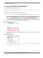
1
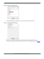
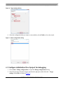
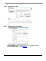
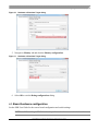
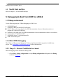
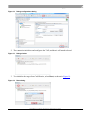
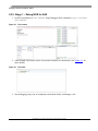
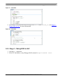
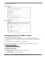
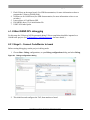
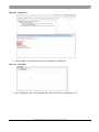
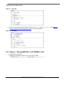
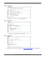
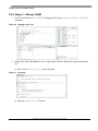
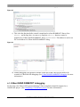
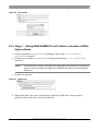
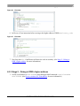
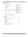
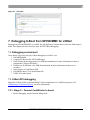
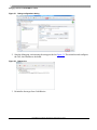
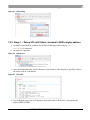
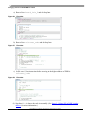
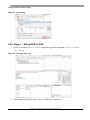
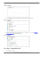
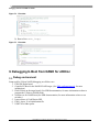
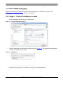
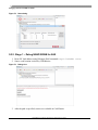
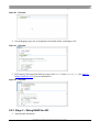
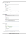
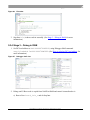
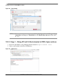
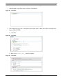
Document Number: AN4876
Freescale Semiconductor
Application Note
CodeWarrior U-Boot Debugging
1. Introduction
This document describes the steps required for U-Boot
debugging using the CodeWarrior IDE.
This document includes the following sections:
•
Configuring and building U-Boot.
•
Creating a CodeWarrior project to debug Uboot.
•
Specifying the launch configuration settings.
•
Debugging U-Boot from NOR, NAND, SPI, and
SD card flash devices for low-end and high-end
Power Architecture CPU.
2. Preliminary background
U-Boot resides in flash memory on target systems and
boots an embedded Linux image or other OS image
(vxworks) or an elf, developed for those systems.
Before debugging U-Boot on a target system, follow
these steps:
1. Install the Board Support Package (BSP) for a
target system you want to debug on the host
Linux machine.
2. Configure the BSP U-Boot package to place
© Freescale Semiconductor, Inc., 2014. All rights reserved.
Contents
1.
2.
3.
4.
5.
6.
7.
Introduction .......................................................1
Preliminary background...................................1
Configuring and building U-Boot ....................2
Configuring a CodeWarrior project .................2
Debugging U-Boot from NOR for e500v2 .......8
Debugging U-Boot from NAND for e500v2 ... 14
Debugging U-Boot from SPI/SD/MMC for e500v2
.......................................................................... 27
8. Debugging U-Boot from NOR for e500mc .... 32
9. Debugging U-Boot from NAND for e500mc .. 38
10. Debugging U-Boot from SPI/SD/MMC for e500mc
.......................................................................... 44
11. How to calculate PIC load address ............... 50
12. Troubleshooting Tips ..................................... 51
Configuring and building U-Boot
debugger symbolic information in the U-Boot binary executable file.
3. Configure hardware to use the U-Boot image. (For more information, see Chapter 7.5.3 of
Targeting PA Processor.pdf)
4. Create a new CodeWarrior project that you will use to debug U-Boot on the target system.
3. Configuring and building U-Boot
After installing BSP, configure and build U-Boot images for CodeWarrior debug. For more information
on configuring and building U-Boot with CodeWarrior debugger support, see the SDK User Manual.
4. Configuring a CodeWarrior project
This section covers:
•
Creating a CodeWarrior project
•
Configure initialization file of project for debugging
•
Board hardware configuration
4.1. Creating a CodeWarrior project
1. Open CodeWarrior IDE.
2. Choose File > Import, to import the U-Boot .elf file generated during the U-Boot compilation. It
can be found in u-boot folder.
Figure 1. CodeWarrior File menu
3. Choose the source to import and select Next.
CodeWarrior U-Boot Debugging Application Note
2
Freescale Semiconductor
Configuring a CodeWarrior project
Figure 2. Import executable file dialog
4. Specify Project name and Location, or use the default location and select Next.
Figure 3. Import executable file dialog
5. Browse to the U-Boot .elf file and select open. By default, CodeWarrior looks for an .elf
extension, so change the file type in lower right corner of select file dialog, as shown in Figure 4.
CodeWarrior U-Boot Debugging Application Note
Freescale Semiconductor
3
Configuring a CodeWarrior project
Figure 4. Select U-Boot elf file
6. Select processor type for the project and select Next.
Figure 5. Select processor type
7. Select Debugger Connection Types, Board, and Connection Type.
CodeWarrior U-Boot Debugging Application Note
4
Freescale Semiconductor
Configuring a CodeWarrior project
Figure 6. Target settings dialog
8. Select the configuration that you want to create and then, select Finish to close the wizard.
Figure 7. Select configuration dialog
4.2. Configure initialization file of project for debugging
1. Choose Run > Debug configurations, to open the Debug configurations dialog.
2. Select Project name from the left pane and from the right pane, under Main tab – Target
settings, select Edit, as shown in Figure 8.
CodeWarrior U-Boot Debugging Application Note
Freescale Semiconductor
5
Configuring a CodeWarrior project
Figure 8. Debug Configurations dialog
3. From the Hardware or Simulator Connection dialog, select Edit to edit the target as shown in
the Figure 9.
Figure 9. Hardware or Simulator Connection dialog
4. From the Initialization tab, browse to the location of U_Boot initialization file and add its
location in the Initialize target, as shown in Figure 10.
CodeWarrior U-Boot Debugging Application Note
6
Freescale Semiconductor
Configuring a CodeWarrior project
Figure 10. Hardware or Simulator Target dialog
5. Navigate to Memory tab and deselect Memory configuration.
Figure 11. Hardware or Simulator Target dialog
6. Select OK to exit the Debug configurations dialog.
4.3. Board hardware configuration
See the SDK User Guide for the correct board configuration and switch settings.
NOTE
U-Boot debug is JTAG-based and a probe needs to be connected to the board.
CodeWarrior U-Boot Debugging Application Note
Freescale Semiconductor
7
Debugging U-Boot from NOR for e500v2
4.4. Useful hints and tips
Refer to Chapter 12, for useful hints and tips.
5. Debugging U-Boot from NOR for e500v2
5.1. Debug environment
Use the following setup for U-Boot debugging on e500v2 core:
•
•
•
•
•
•
•
P1010RDB board.
Compiled U-Boot for the NOR FLASH target.
Flash U-Boot on the target board. (See SDK documentation, for more information on how to
program the U-Boot to NOR flash.)
Switches set for NOR boot. (See SDK documentation, for more information on how to set switches.)
Latest release of CodeWarrior IDE.
P1010RDB_uboot_32.tcl initialization file.
USB TAP or other probe.
5.2. U-Boot NOR debugging
The U-Boot .elf file generated during the U-Boot compilation should be imported as CodeWarrior
project. (See Configuring a CodeWarrior project, for more information.)
5.2.1. Stage 0 – Connect CodeWarrior to a board
Before debugging, run the board in the debug mode.
1. Choose Run > Debug configurations, to open Debug configurations dialog and select Debug,
as shown in Figure 12.
CodeWarrior U-Boot Debugging Application Note
8
Freescale Semiconductor
Debugging U-Boot from NOR for e500v2
Figure 12. Debug configurations dialog
2. The connection initializes and configures the TAP, and then it will attach to board.
Figure 13. Debug window
3. To reinitialize the target from CodeWarrior, select Reset, as shown in Figure 14.
Figure 14. Reset dialog
CodeWarrior U-Boot Debugging Application Note
Freescale Semiconductor
9
Debugging U-Boot from NOR for e500v2
5.2.2. Stage 1 – Debug NOR for AS0
1. Set PIC load address as 0xfff80000, using Debugger Shell command setpicloadaddr
0xfff80000.
Figure 15. File location
2. After the path is provided, source will become available in CodeWarrior. (See Figure 15, for
more details.)
Figure 16. File editor
3. Now debugging (step, run, or breakpoint) can be done before switching to AS1.
CodeWarrior U-Boot Debugging Application Note
10
Freescale Semiconductor
Debugging U-Boot from NOR for e500v2
Figure 17. File editor
4. In file start.S, last instruction before moving to AS1 is rfi before switch_as. (See Stage 2 –
Debug NOR for AS1, for more information.)
Figure 18. File editor
5.2.3. Stage 2 – Debug NOR for AS1
1. Step Into rfi instruction.
2. Reset PIC load address, using Debugger Shell command setpicloadaddr reset.
CodeWarrior U-Boot Debugging Application Note
Freescale Semiconductor
11
Debugging U-Boot from NOR for e500v2
Figure 19. Debugger shell view
3. Debugging (step, run, or breakpoint) can be done until code is relocated in DDR.
a) Run to Line: board_init_f and Step Into.
Figure 20. File editor
b) Run to Line: relocate_code and Step Into.
Figure 21. File editor
CodeWarrior U-Boot Debugging Application Note
12
Freescale Semiconductor
Debugging U-Boot from NOR for e500v2
c) In start.S, last instruction before relocate to DDR is relocate_code.
Figure 22. File editor
d) Step Into blr, it shows the code in assembly. (See Stage 3 – Debug in DDR’s higher address,
for more information.)
5.2.4. Stage 3 – Debug in DDR’s higher address
1. Set the PIC load address as 0x3ff30000 using Debugger Shell command setpicloadaddr
0x3ff30000. (See How to calculate PIC load address, for more information.)
Figure 23. Debugger shell view
2. You can debug until U-Boot is running.
a) Run to Line: board_init_r and do Step into.
CodeWarrior U-Boot Debugging Application Note
Freescale Semiconductor
13
Debugging U-Boot from NAND for e500v2
Figure 24. File editor
b) Run to Line: main_loop()
Figure 25. File editor
6. Debugging U-Boot from NAND for e500v2
U-Boot NAND boot is a 2-stage booting process:
• First stage (U-Boot NAND SPL) – when turned on and on reset, U-Boot NAND SPL gets the
control. It runs from IFC’s internal SRAM and it copies U-Boot RAMBOOT to DDR and transfers
control to it.
• Second stage (U-Boot NAND RAMBOOT) – RAMBOOT code.
Depending upon the booting stage, U-Boot NAND debugging can be classified into two modes:
• U-Boot NAND SPL debugging
• U-Boot NAND RAMBOOT debugging
6.1. Debug environment
Use the following setup for U-Boot NAND debugging on e500v2 core:
1. P1010RBD board.
2. Compiled U-Boot for the NAND FLASH target.
CodeWarrior U-Boot Debugging Application Note
14
Freescale Semiconductor
Debugging U-Boot from NAND for e500v2
3. Flash U-Boot on the target board. (See SDK documentation, for more information on how to
program the U-Boot to NAND flash.)
4. Switches set for NAND boot (See SDK documentation, for more information on how to set
switches.)
5. Latest release of CodeWarrior IDE.
6. P1010RDB_uboot_32.tcl initialization file.
7. USB TAP or other probe.
6.2. U-Boot NAND SPL debugging
For this stage the U-Boot-spl elf file generated during U-Boot compilation should be imported as a
CodeWarrior project. (See Configuring a CodeWarrior project, for more details.)
6.2.1. Stage 0 – Connect CodeWarrior to board
Before starting debugging, run the project in debug mode.
1. Choose Run > Debug configurations, to open Debug configurations dialog and select Debug.
Figure 26. Debug configurations dialog
2. This initializes and configures the TAP, then attaches to board.
CodeWarrior U-Boot Debugging Application Note
Freescale Semiconductor
15
Debugging U-Boot from NAND for e500v2
Figure 27. Debug view
3. Reinitialize the target from CodeWarrior, using the U-Boot initialization file.
Figure 28. Reset dialog
6.2.2. Stage 1 – Debug NAND SPL in IFC SRAM for AS0
1. Browse to the location, where the source file is saved, as shown in Figure 29.
CodeWarrior U-Boot Debugging Application Note
16
Freescale Semiconductor
Debugging U-Boot from NAND for e500v2
Figure 29. Debug view
2. After the path is specified, the source is available in CodeWarrior.
Figure 30. File editor
3. Now, debugging (step, run, or breakpoint) can be done before switching to AS1.
CodeWarrior U-Boot Debugging Application Note
Freescale Semiconductor
17
Debugging U-Boot from NAND for e500v2
Figure 31. File editor
4. In file start.S, last instruction before moving to AS1 is rfi before switch_as. (See Stage 2 –
Debug NAND SPL in IFC SRAM for AS1, for more information.)
Figure 32. File editor
6.2.3. Stage 2 – Debug NAND SPL in IFC SRAM for AS1
1. Step Into this instruction.
2. Debugging is possible until the code is relocated to DDR.
a) Run to Line: board_init_f and Step Into: board_init_f.
CodeWarrior U-Boot Debugging Application Note
18
Freescale Semiconductor
Debugging U-Boot from NAND for e500v2
Figure 33. File editor
b) Run to Line: relocate_code and do Step Into.
Figure 34. File editor
c) In file start.S, last code before relocate to DDR is relocate_code.
Figure 35. File editor
3. Step Into: blr, it shows code in assembly. (See Stage 3 – Debug in RAM, for more information.)
CodeWarrior U-Boot Debugging Application Note
Freescale Semiconductor
19
Debugging U-Boot from NAND for e500v2
6.2.4. Stage 3 – Debug in RAM
1. Set PIC load address as 0x100000 in Debugger Shell using setpicloadaddr 0x100000
command.
Figure 36. Debugger shell view
2. Debug until U-Boot RAMBOOT code is copied from NAND to RAM and control is transferred
to it.
a) Run to Line: board_init_r and do Step Into.
Figure 37. File editor
b) Step Into: nand_boot() function.
CodeWarrior U-Boot Debugging Application Note
20
Freescale Semiconductor
Debugging U-Boot from NAND for e500v2
Figure 38.
c) This is the last function before control is transferred to u-boot RAMBOOT. Run to Line:
uboot() and do Step Into. As soon as we Step Into uboot() function, control is
transferred to U-Boot NAND RAMBOOT, that is, 0x00200000. This address is used to set
PIC load address for U-Boot NAND RAMBOOT debug.
Figure 39.
d) Further debugging is not possible with this u-boot-spl.elf and a new project needs to be
created for U-Boot NAND debugging. (See U-Boot NAND RAMBOOT debugging, for more
information.)
6.3. U-Boot NAND RAMBOOT debugging
For this stage, the U-Boot elf file generated during U-Boot compilation should be imported as a
CodeWarrior project. (See Configuring a CodeWarrior project, for more information.)
CodeWarrior U-Boot Debugging Application Note
Freescale Semiconductor
21
Debugging U-Boot from NAND for e500v2
6.3.1. Stage 0 – Connect CodeWarrior to board
1. Restart the board. U-Boot starts and relocates itself into RAM.
2. Before Debugging, run the board in Debug mode.
Figure 40. Debug configurations dialog
3. This initializes and configures the TAP, then attaches to the board.
Figure 41. Debug view
4. Reinitialize the target from CodeWarrior, using the U-Boot initialization file.
CodeWarrior U-Boot Debugging Application Note
22
Freescale Semiconductor
Debugging U-Boot from NAND for e500v2
Figure 42. Reset dialog
6.3.2. Stage 1 – Debug NAND RAMBOOT until U-Boot is relocated to DDR’s
higher address
1. Set PIC load address as 0x00200000 in Debugger Shell, using setpicloadaddr
0x00200000 command.
2. Set break point at address 0x00200008 in Debugger Shell using bp -hw 0x00200008
command.
NOTE
The break point’s address is needed to be offset with 8 bytes because it is required to
jump over the instructions that enables the MSR[DE] bit, otherwise the break point
will not hit.
3. Resume core operation.
Figure 43. Debug view
4. When break point is hit, source code location is asked by CodeWarrior. After the path is
specified, it shows the source code in CodeWarrior.
CodeWarrior U-Boot Debugging Application Note
Freescale Semiconductor
23
Debugging U-Boot from NAND for e500v2
Figure 44. File editor
5. Now debugging (step, run, or breakpoint) can be done until U-Boot code is relocated to the
higher address of DDR.
a) Run to Line: board_init_f and do Step Into.
Figure 45. File editor
b) Run to Line: relocate_code and do Step Into.
CodeWarrior U-Boot Debugging Application Note
24
Freescale Semiconductor
Debugging U-Boot from NAND for e500v2
Figure 46. File editor
6. In file start.S, last instruction before moving to the higher address of DDR is relocate_code.
Figure 47. File editor
7. Now Step Into blr, CodeWarrior will show the code in assembly. (See Stage 2 – Debug in
DDR’s higher address, for more information.)
6.3.3. Stage 2 – Debug in DDR’s higher address
1. Set PIC load address as 0x3ff2f000 using Debugger Shell command setpicloadaddr
0x3ff2f000. (See How to calculate PIC load address, for more information.)
CodeWarrior U-Boot Debugging Application Note
Freescale Semiconductor
25
Debugging U-Boot from NAND for e500v2
Figure 48. Debugger shell view
2. You can debug until U-Boot is running.
a) Run to Line: board_init_r and Step Into.
Figure 49. File editor
b) Run to Line: main_loop()
CodeWarrior U-Boot Debugging Application Note
26
Freescale Semiconductor
Debugging U-Boot from SPI/SD/MMC for e500v2
Figure 50. File editor
7. Debugging U-Boot from SPI/SD/MMC for e500v2
Booting from SPI and SD\MMC are similar, the only difference between these is how the final image is
build. This chapter provides necessary steps for SPI U-Boot debugging.
7.1. Debugging environment
Given below is the setup used for U-Boot debugging on e500v2 core:
1. P1010RDB board.
2. Compiled U-Boot for the SPI FLASH target.
3. Flash U-Boot on the target board. (See SDK documentation, for more information on how to
program the U-Boot to SPI flash.)
4. Switches set for SPI boot. (See SDK documentation for more information on how to set
switches.)
5. Latest release of CodeWarrior IDE.
6. P1010RDB_uboot_32.tcl initialization file.
7. USB TAP or other probe.
7.2. U-Boot SPI debugging
Import the U-Boot elf file, generated during U-Boot compilation as a CodeWarrior project. (See
Configuring a CodeWarrior project, for more information.)
7.2.1. Stage 0 – Connect CodeWarrior to board
1. Before debugging, run the board in debug mode.
CodeWarrior U-Boot Debugging Application Note
Freescale Semiconductor
27
Debugging U-Boot from SPI/SD/MMC for e500v2
Figure 51. Debug configurations dialog
2. Start the debugging session using the setup provided in Figure 51. This initializes and configures
the TAP, then attaches to the board.
Figure 52. Debug view
3. Reinitialize the target from CodeWarrior.
CodeWarrior U-Boot Debugging Application Note
28
Freescale Semiconductor
Debugging U-Boot from SPI/SD/MMC for e500v2
Figure 53. Reset dialog
7.2.2. Stage 1 – Debug SPI until U-Boot relocated to DDR’s higher address
1. Set hardware break point at address 0x1107f008 in Debugger Shell using bp –hw
0x1107f008 command.
2. Resume core operation.
Figure 54. Debug view
3. Once the break point is hit, specify the source code location. After the path is specified, it shows
the source code in CodeWarrior.
Figure 55. File editor
4. Now debugging (step, run, or breakpoint) can be done until U-Boot code is relocated to the
higher address of DDR.
CodeWarrior U-Boot Debugging Application Note
Freescale Semiconductor
29
Debugging U-Boot from SPI/SD/MMC for e500v2
a) Run to Line: board_init_f and do Step Into.
Figure 56. File editor
b) Run to Line: relocate_code and do Step Into.
Figure 57. File editor
c) In file start.S, last instruction before moving to the higher address of DDR is
relocate_code.
Figure 58. File editor
d) Step Into blr, it shows the code in assembly. (See Stage 2– Debug SPI in DDR’s higher
address, for more information.)
CodeWarrior U-Boot Debugging Application Note
30
Freescale Semiconductor
Debugging U-Boot from SPI/SD/MMC for e500v2
NOTE
To find the correct address for hardware break point, that is, 0x1107008,
disassembly on u-boot.elf is done and the _start_e500 address is searched for.
Add 8 to this address to have the correct address for hardware break point.
7.2.3. Stage 2– Debug SPI in DDR’s higher address
1. Set PIC load address as 0x3ff30000 using Debugger Shell command setpicloadaddr
0x3ff30000. (See How to calculate PIC load address, for more information.)
Figure 59. File editor
2. Run to Line: board_init_r and do Step Into.
Figure 60. File editor
3. Run to Line: main_loop().
CodeWarrior U-Boot Debugging Application Note
Freescale Semiconductor
31
Debugging U-Boot from NOR for e500mc
Figure 61. File editor
8. Debugging U-Boot from NOR for e500mc
8.1. Debug environment
Setup used for U-Boot debugging on e500mc core:
1. P3041DS Hydra board.
2. Compiled U-Boot for the NOR FLASH target.
3. Flash U-Boot on the target board. (See SDK documentation, for more information on how to
program the U-Boot to NOR flash.)
4. Switches set for NOR boot (See SDK documentation, for more information on how to set
switches.)
5. Latest release of CodeWarrior IDE.
6. P3041DS_uboot_36.tcl initialization file.
7. USB TAP or other probe.
8.2. U-Boot NOR debugging
U-Boot elf file generated during U-Boot compilation should be imported as CodeWarrior project. (See
Configuring a CodeWarrior project, for more information.)
8.2.1. Stage 0 – Connect CodeWarrior to board
1. Before debugging, run the board in debug mode.
CodeWarrior U-Boot Debugging Application Note
32
Freescale Semiconductor
Debugging U-Boot from NOR for e500mc
Figure 62. Debug configurations dialog
2. Start the debugging session using the setup provided in Figure 62. This initializes and configures
the TAP, then attaches to the board.
Figure 63. Debug view
3. Reinitialize the target from CodeWarrior.
CodeWarrior U-Boot Debugging Application Note
Freescale Semiconductor
33
Debugging U-Boot from NOR for e500mc
Figure 64. Reset dialog
8.2.2. Stage 1 – Debug NOR for AS0
1. Set PIC load address as 0xfff80000 using Debugger Shell command setpicloadaddr
0xfff80000.
Figure 65. Debugger shell view
2. After the path is specified, source code is available in CodeWarrior.
CodeWarrior U-Boot Debugging Application Note
34
Freescale Semiconductor
Debugging U-Boot from NOR for e500mc
Figure 66. File editor
3. Now debugging (step, run, or breakpoint) can be done before switching to AS1.
Figure 67. File editor
4. In start.S, last instruction before moving to AS1 is rfi before switch_as. (See Stage 2 –
Debug NOR for AS1, for more information.)
Figure 68. File editor
8.2.3. Stage 2 – Debug NOR for AS1
1. Step Into this instruction.
CodeWarrior U-Boot Debugging Application Note
Freescale Semiconductor
35
Debugging U-Boot from NOR for e500mc
2. Reset PIC load address using Debugger Shell command setpicloadaddr reset.
Figure 69. Debugger shell view
3. Now debugging (step, run, or breakpoint) can be done until code is relocated in DDR.
a) Run to Line: board_init_f and Step Into.
Figure 70. File editor
b) Run to Line: relocate_code and Step Into.
Figure 71. File editor
CodeWarrior U-Boot Debugging Application Note
36
Freescale Semiconductor
Debugging U-Boot from NOR for e500mc
c) In start.S, last instruction before relocate to DDR is relocate_code.
Figure 72. File editor
d) Step Into blr, it shows assembly code. (See Stage 3 – Debug in DDR’s higher address, for
more information.)
8.2.4. Stage 3 – Debug in DDR’s higher address
1. Set PIC load address as 0x7ff30000 using Debugger Shell command setpicloadaddr
0x7ff30000. (See How to calculate PIC load address, for more information.)
Figure 73. Debugger shell view
2. We can debug until U-Boot is running.
a) Run to Line: board_init_r and do Step into.
CodeWarrior U-Boot Debugging Application Note
Freescale Semiconductor
37
Debugging U-Boot from NAND for e500mc
Figure 74. File editor
b) Run to Line: main_loop().
Figure 75. File editor
9. Debugging U-Boot from NAND for e500mc
9.1. Debug environment
Setup used for U-Boot NAND debugging on e500mc core:
1. P3041DS Hydra board.
2. Compiled U-Boot for the NAND FLASH target. (See PBL configuration tool, for more
information.)
3. Flash U-Boot on the target board. (See SDK documentation, for more information on how to
program the U-Boot to NAND flash.)
4. Switches set for NAND boot (See SDK documentation, for more information on how to set
switches.)
5. Latest release of CodeWarrior IDE.
6. P3041_uboot_36.tcl initialization file.
7. USB TAP or other probe.
CodeWarrior U-Boot Debugging Application Note
38
Freescale Semiconductor
Debugging U-Boot from NAND for e500mc
9.2. U-Boot NAND debugging
Import the U-Boot elf file generated during U-Boot compilation as a CodeWarrior project. (See
Configuring a CodeWarrior project, for more information.)
9.2.1. Stage 0 – Connect CodeWarrior to board
1. Before debugging, run the project in debug mode.
Figure 76. Debug configurations dialog
2. Start the debugging session using the setup provided in Figure 76. This initializes and configures
the TAP, then attaches to the board.
Figure 77. Debug view
3. Reinitialize the target from CodeWarrior, using U-Boot initialization file.
CodeWarrior U-Boot Debugging Application Note
Freescale Semiconductor
39
Debugging U-Boot from NAND for e500mc
Figure 78. Reset dialog
9.2.2. Stage 1 – Debug NAND SRAM for AS0
1. Reset PIC load address using Debugger Shell command setpicloadaddr reset.
2. Source code location is asked by CodeWarrior.
Figure 79. Debug view
3. After the path is specified, sources are available in CodeWarrior.
CodeWarrior U-Boot Debugging Application Note
40
Freescale Semiconductor
Debugging U-Boot from NAND for e500mc
Figure 80. File editor
4. Now debugging (step, run, or breakpoint) can be done before switching to AS1.
Figure 81. File editor
5. In file start.S, last instruction before moving to AS1 is rfi before switch_as. (See Stage 2 –
Debug NAND for AS1, for more information.)
Figure 82. File editor
9.2.3. Stage 2 – Debug NAND for AS1
1.
Step Into this instruction.
CodeWarrior U-Boot Debugging Application Note
Freescale Semiconductor
41
Debugging U-Boot from NAND for e500mc
Figure 83. File editor
2. Now debugging is be possible, before the code is relocated in DDR.
a) Run to Line: board_init_f and Step into: board_init_f.
Figure 84. File editor
b) Run to Line: relocate_code and do Step Into.
Figure 85. File editor
c) In file start.S, last code before relocate to DDR is relocate_code.
CodeWarrior U-Boot Debugging Application Note
42
Freescale Semiconductor
Debugging U-Boot from NAND for e500mc
Figure 86. File editor
3. Step Into: blr, it shows code in assembly. (See Stage 3 – Debug in RAM, for more
information.)
9.2.4. Stage 3 – Debug in RAM
1. Set PIC load address as 0xFFFFFFFF7FFB0020, using Debugger Shell command
setpicloadaddr 0xFFFFFFFF7FFB0020. (See How to calculate PIC load address, for
more information.)
Figure 87. Debugger shell view
2. Debug until U-Boot code is copied from NAND to RAM and control is transferred to it.
a) Run to Line: board_init_r and do Step Into.
CodeWarrior U-Boot Debugging Application Note
Freescale Semiconductor
43
Debugging U-Boot from SPI/SD/MMC for e500mc
Figure 88. File editor
b) Step Into: main_loop() function.
Figure 89. File editor
10. Debugging U-Boot from SPI/SD/MMC for e500mc
Booting from SPI and SD\MMC are similar, the only difference between these is, how the final image is
build. This chapter provides steps for SPI U-Boot debugging.
10.1. Debugging environment
Given below is the setup used for U-Boot debugging on e500mc core:
1. Compiled U-Boot for SPI FLASH target.
2. Flash U-Boot on the target board. (For more information, see Chapter 7.6.1.1 Using the Boot
Format Tool, of Targeting PA Processor.pdf)
3. Switches set for SPI boot. (See SDK documentation, for more information on how to set
switches.)
4. Latest release of CodeWarrior IDE.
5. P3041_uboot_36.tcl initialization file.
6. USB TAP or other probe.
CodeWarrior U-Boot Debugging Application Note
44
Freescale Semiconductor
Debugging U-Boot from SPI/SD/MMC for e500mc
10.2. U-Boot SPI debugging
Import the U-Boot elf file generated during U-Boot compilation as CodeWarrior project. (See
Configuring a CodeWarrior project, for more information.)
10.2.1. Stage 0 – Connect CodeWarrior to board
1. Before debugging, run the board in debug mode.
Figure 90. Debug configurations dialog
2. Start the debugging session using the setup provided in Figure 87. This initializes and configures
the TAP, then attaches to the board.
Figure 91. Debug view
3. Reinitialize the target from CodeWarrior.
CodeWarrior U-Boot Debugging Application Note
Freescale Semiconductor
45
Debugging U-Boot from SPI/SD/MMC for e500mc
Figure 92. Reset dialog
NOTE
If Reset Failed error appears go to Debug Configurations, edit Target settings
connection, and then go to Advanced tab, select Reset delay (ms) and set the value
to 2000.
10.2.2. Stage 1 – Debug SPI until U-Boot relocated to DDR’s higher address
1. Reset PIC load address, using Debugger Shell command setpicloadaddr reset.
2. Source code location is asked by CodeWarrior.
Figure 93. Debug view
CodeWarrior U-Boot Debugging Application Note
46
Freescale Semiconductor
Debugging U-Boot from SPI/SD/MMC for e500mc
3. After the path is specified, source will be in CodeWarrior.
Figure 94. File editor
4. Now debugging (step, run, or breakpoint) can be done until U-Boot code will be relocated to the
higher address of DDR.
a) Step Into:
Figure 95. File editor
b) Run to Line: board_ini_f and do Step Into.
Figure 96. File editor
CodeWarrior U-Boot Debugging Application Note
Freescale Semiconductor
47
Debugging U-Boot from SPI/SD/MMC for e500mc
c) Run to Line: relocate_code and do Step Into.
Figure 97. File editor
d) In file start.S, last instruction before moving to DDR’s higher address is relocate_code.
Figure 98. File editor
e) Step Into: blr, it shows code in assembly. (See Stage 2 – Debug SPI in DDR’s higher
address, for more information.)
10.2.3. Stage 2 – Debug SPI in DDR’s higher address
1. Set PIC load address as 0xffffffff7ffb0020 using Debugger Shell command
setpicloadaddr 0xffffffff7ffb0020. (See How to calculate PIC load address, for
more information.)
CodeWarrior U-Boot Debugging Application Note
48
Freescale Semiconductor
Debugging U-Boot from SPI/SD/MMC for e500mc
Figure 99. Debugger shell view
2. Run to Line: board_init_r and do Step Into.
Figure 100. File editor
3. Run to Line: main_loop().
Figure 101. File editor
CodeWarrior U-Boot Debugging Application Note
Freescale Semiconductor
49
How to calculate PIC load address
11. How to calculate PIC load address
To set the PIC load address, apply this formula:
PIC address = Runtime symbol address (RAM symbol address in our case)
– Compile time symbol address
After Step Into: blr , in Debugger Shell perform these operations:
1. %>setpicloadaddr 0x0: It tells the debugger that the main executables are loaded at 0x0.
NOTE
This is not the same as setpicloadaddr reset command, which tells the
debugger that the main executables are loaded at the address set in the ELF.
2. %>bp –hw in_ram: It shows the compile time symbol address.
Figure 102. Debugger shell view
3. Calculate the difference between PC address (single step after blr instruction) and compile time
symbol address.
Figure 103. Disassembly view
PIC address = 0X7FF315B8 (PC address) – 0x000015B8 (in_ram break
point address) = 0x7FF30000.
CodeWarrior U-Boot Debugging Application Note
50
Freescale Semiconductor
Troubleshooting Tips
12. Troubleshooting Tips
This section explains:
• Selecting the correct breakpoint type
• Risky memory maps
• Setting multiple hardware breakpoints
• Skipping U-Boot stages effectively
• Setting correct absolute addresses
• Secure Boot and U-Boot debug
12.1. Selecting the correct breakpoint type
To avoid issues with incorrect interpretation of memory access during the various U-Boot stages, ensure
you use hardware breakpoints only when you have successfully reached the first breakpoint in RAM.
The debugger tries to do modify the target memory map and breakpoints, but you can avoid risks by
sticking to hardware breakpoints during initial bring-up.
12.2. Risky memory maps
Some SoCs do not provide access to invalid memory ranges and get locked due to unfinished
transactions. In such cases, the debug session needs to be restarted. When performing early U-Boot,
consider the following points:
• Do not open the Memory or Memory Browser views for ranges that are not actually readable
yet and do not leave them open if you know that the next reset will render them inaccessible.
• For U-Boot debug, your debugger init script should be nearly empty, but it should contain at
least a reg sp=1 line. This prohibits the debugger in the very early stages from trying to show
a stack back trace that causes invalid accesses, if there is no stack yet.
12.3. Setting multiple hardware breakpoints
The number of active hardware breakpoints is limited, but you can use the Breakpoints view to disable
those that are not relevant right now and then add more. This way you can create a library of breakpoints
that persists across project debug cycles. Whenever you need a specific one, you can enable it and
disable others to stay within the limits of the available hardware breakpoints. Also remember that the
debugger requires a free hardware breakpoint to do specific operations like step over. To avoid error
messages, monitor how many hardware breakpoints you have enabled at a specific point of time.
12.4. Skipping U-Boot stages effectively
Remember that setpiclaodaddr automatically relocates all active source related breakpoints to the
space where a PIC executable is loaded. This means that you can pick a specific breakpoint from your
library of source related hardware breakpoints and use setpiclaodaddr to instantiate it for an
appropriate stage of U-Boot debug. For example, if you have determined that U-Boot will relocate to
0x7ff30000 in RAM, run the following sequence:
CodeWarrior U-Boot Debugging Application Note
Freescale Semiconductor
51
Troubleshooting Tips
1. reset hard
2. %>bp –hw in_ram: Assuming this breakpoint is not yet enabled in your Breakpoints view.
3. %>setpicloadaddr 0x7ff30000: It instantiates the hardware breakpoint at the right address.
Check the Breakpoints view.
4. %>go: It runs through all the various memory map changes and stops on in_ram breakpoint in
RAM.
Similarly, you can go straight to board_init_f breakpoint:
1. reset hard
2. %>bp –hw board_init_f: Assuming that this breakpoint is not yet enabled in your
Breakpoints view.
3. %>setpicloadaddr reset: For a NOR flash setup, board_init_f runs in the address
range to which U-Boot was linked to. So, reset is ok.
4. %>go: It runs through all the various memory map changes and stops on board_init_f
breakpoint in NOR.
12.5. Setting correct absolute addresses
Absolute hex addresses shown in this application note for the setpiclaodaddr command or
breakpoint operations are common for Freescale provided setups. For example, a 512KB U-Boot starts
in NOR flash at 0xfff80000 and is linked to 0xeff80000. Relocation to RAM is based on RAM
sizes. All these perceived absolute values can change depending on the U-Boot size and configuration.
So, if your U-Boot configuration differs from the one shown, adjust the addresses used appropriately. Go
manually from one debugging stage to another debugging stage during debug, and you will see to what
extent addresses may be different for your setup. Then you will know all the required values for
subsequent runs.
12.6. Secure Boot and U-Boot debug
When using Secure Boot, remember that ESBC starts at a different virtual address as configured using
CSF after ISBC has verified it, and not from 0xfffffffc. If you try to debug U-Boot without
considering this, the debugger shows you the ESBC code starting at 0xfffffffc when it is internally
executing an invisible ROM ISBC at those addresses. This shows a discrepancy in the assembly code
and execution behavior. If by using CSF you get, for example, 0xcffffffc as ESBC entry vector,
then set an initial hardware breakpoint on the ESBC entry and adjust the source mapping with
setpiclaodaddr appropriately. Then run from the original reset vector to your breakpoint and skip
the invisible ISBC from ROM completely. This procedure can also be entered into lines of a debugger
initialization files so that ISBC is automatically skipped when you start debugging ESBC.
CodeWarrior U-Boot Debugging Application Note
52
Freescale Semiconductor
How to Reach Us:
Home Page:
www.freescale.com
E-mail:
[email protected]
Information in this document is provided solely to enable system and software implementers to use
Freescale Semiconductor products. There are no express or implied copyright licenses granted
hereunder to design or fabricate any integrated circuits or integrated circuits based on the information in
this document.
Freescale reserves the right to make changes without further notice to any products herein. Freescale
makes no warranty, representation, or guarantee regarding the suitability of its products for any
particular purpose, nor does Freescale assume any liability arising out of the application or use of any
product or circuit, and specifically disclaims any and all liability, including without limitation
consequential or incidental damages. “Typical” parameters that may be provided in Freescale data
sheets and/or specifications can and do vary in different applications, and actual performance may vary
over time. All operating parameters, including “typicals,” must be validated for each customer application
by customer's technical experts. Freescale does not convey any license under its patent rights nor the
rights of others. Freescale sells products pursuant to standard terms and conditions of sale, which
can be found at the following address: freescale.com/SalesTermsandConditions.
Freescale, the Freescale logo, AltiVec, C-5, CodeTest, CodeWarrior, ColdFire, ColdFire+, C-Ware,
Energy Efficient Solutions logo, Kinetis, mobileGT, PowerQUICC, Processor Expert, QorIQ, Qorivva,
StarCore, Symphony, and VortiQa are trademarks of Freescale Semiconductor, Inc., Reg. U.S. Pat. &
Tm. Off. Airfast, BeeKit, BeeStack, CoreNet, Flexis, Layerscape, MagniV, MXC, Platform in a Package,
QorIQ Qonverge, QUICC Engine, Ready Play, SafeAssure, SafeAssure logo, SMARTMOS, Tower,
TurboLink, Vybrid, and Xtrinsic are trademarks of Freescale Semiconductor, Inc. All other product or
service names are the property of their respective owners.
© Freescale Semiconductor, Inc. 2014.
Document Number: AN4876
28 April 2014