1
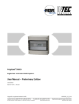
PolyGard Controller MGC2-04 Multi-Point Controller Serial Number – S00 User Manual December 01, 2008 November 19, 2013 – Revision Polygard® is a registered trademark of MSR Customer Services (858) 578-7887 & (888) GO INTEC Fax (858) 578-4633 & (888) FX INTEC www.inteccontrols.com INTEC Controls, 12700 Stowe Dr. Suite 100, Poway, CA 92064 MGC2-04 Specification subject to change without notice. Printed in USA 131119 PolyGard® Multi-Point Controller User Manual - MGC2-04 Page 02 1 Description............................................................................................................................................. 4 2 Operating Instruction ............................................................................................................................ 5 2.1 Description Keypad User Interface ................................................................................................... 5 2.2 Setting / Change Parameters ........................................................................................................... 5 2.3 Password Level ................................................................................................................................ 6 3 Menu Overview ...................................................................................................................................... 7 3.1 Malfunction management ................................................................................................................. 8 3.1.1 Acknowledge a malfunction ....................................................................................................... 8 3.1.2 History error summary ............................................................................................................... 8 3.1.3 System Errors............................................................................................................................ 9 3.2 Stage Status ..................................................................................................................................... 9 3.3 Relay Status ..................................................................................................................................... 9 3.3.1 Manual operation of the relays ................................................................................................ 10 3.4 Menu Sensor Readings .................................................................................................................. 10 3.5 Menu Relay Setup .......................................................................................................................... 11 3.5.1 Relay Mode ............................................................................................................................. 11 3.5.2 Relay Action Steady / Flash..................................................................................................... 11 3.5.3 Latching Mode......................................................................................................................... 12 3.5.4 Horn Function.......................................................................................................................... 12 3.5.5 External operation of Relay. .................................................................................................... 13 3.5.6 Delay operation of Relay. ........................................................................................................ 13 3.6 Menu SP Setup .............................................................................................................................. 14 3.6.1 Activate – Deactivate SP ......................................................................................................... 15 3.6.2 Selection Type......................................................................................................................... 16 3.6.3 Measuring range...................................................................................................................... 16 3.6.4 SP Signal................................................................................................................................. 16 3.6.5 Stage/Setpoint / Hysteresis ..................................................................................................... 17 3.6.6 Delay time ON or OFF............................................................................................................. 17 3.6.7 Control Mode........................................................................................................................... 17 3.6.8 Assigned SP Fault to Relay ..................................................................................................... 17 3.6.9 Assign Relay to a Stage .......................................................................................................... 18 3.6.10 Assigned SP Signal to analog Output...................................................................................... 18 3.7 Menu System Setup ....................................................................................................................... 19 3.7.1 Service Mode .......................................................................................................................... 20 3.7.2 Software Version ..................................................................................................................... 21 3.7.3 Maintenance Concept.............................................................................................................. 21 3.7.4 Average Function .................................................................................................................... 21 3.7.5 Time, Date............................................................................................................................... 21 3.7.6 Customer Password (Code 1) ................................................................................................. 22 3.7.7 Analog Output ......................................................................................................................... 22 3.7.8 Define the Failure Relay .......................................................................................................... 22 3.7.9 Power On Time ....................................................................................................................... 22 3.7.10 Activation of expansions modules for larger systems .............................................................. 22 4 Mounting / Electrical Connection ....................................................................................................... 23 4.1 Electrical Connection ...................................................................................................................... 23 4.2 Unit position – Connection diagram ................................................................................................ 24 Polygard® is a registered trademark of MSR Customer Services (858) 578-7887 & (888) GO INTEC Fax (858) 578-4633 & (888) FX INTEC www.inteccontrols.com INTEC Controls, 12700 Stowe Dr., Suite 100, Poway, CA 92064 MGC2-04 Specification subject to change without notice. Printed in USA 131119 PolyGard® Multi-Point Controller User Manual - MGC2-04 Page 03 5 Start-up Operation ............................................................................................................................... 26 5.1 Start-up........................................................................................................................................... 26 5.2 Checklist Start-up operation ........................................................................................................... 27 6 Configuration- and Parameter card.................................................................................................... 28 6.1 Configurations System Setup ......................................................................................................... 28 6.2 Relay Setup .................................................................................................................................... 28 6.3 Sensor Setup.................................................................................................................................. 28 7 Specifications MG2-04......................................................................................................................... 29 8 Notes and General Information........................................................................................................... 31 8.1 Intended product application........................................................................................................... 31 8.2 Installers` responsibilities................................................................................................................ 31 8.3 Maintenance ................................................................................................................................... 31 8.4 Limited warranty ............................................................................................................................. 31 Polygard® is a registered trademark of MSR Customer Services (858) 578-7887 & (888) GO INTEC Fax (858) 578-4633 & (888) FX INTEC www.inteccontrols.com INTEC Controls, 12700 Stowe Dr., Suite 100, Poway, CA 92064 MGC2-04 Specification subject to change without notice. Printed in USA 131119 PolyGard® Multi-Point Controller User Manual - MGC2-04 Page 04 Multi Point Controller MGC2 1 Description The PolyGard® Multi Point Controller MGC2 is used for the monitoring and warning of sensor points exceeding their stage setpoints. External Transmitters can monitor and warn of toxic, combustible and refrigerant gases as well as temperature and humidity. The Controller MGC2 can measure up to four analog 4 to 20 mA (Gas) Transmitters.. Each Sensor Point (SP) can have five stage thresholds. Each stage threshold can be assigned to anyone of the relays (R1…R5). The Controller can interface via two 4 to 20 mA outputs to any compatible electronic analog control, DDC/PLC control or automation system. The adjustable parameters and staged thresholds make this system very flexible for sensor measuring and control. The configuration of parameter settings and operation is easy to do without any programming knowledge. PolyGard® Multi Point Controller MGC2 must not be used in areas requiring explosion proof equipment. Polygard® is a registered trademark of MSR Customer Services (858) 578-7887 & (888) GO INTEC Fax (858) 578-4633 & (888) FX INTEC www.inteccontrols.com INTEC Controls, 12700 Stowe Dr., Suite 100, Poway, CA 92064 MGC2-04 Specification subject to change without notice. Printed in USA 131119 PolyGard® Multi-Point Controller User Manual - MGC2-04 2 Page 05 Operating Instruction The complete configuration, parameterization and service are made via the keypad user interface in combination with the display screen. Security is provided via two password levels. Fault Alarm INTEC Controls 01.22.05 10:28 am 2.1 Description Keypad User Interface Exits programming and saves settings, returns to the previous menu level. Enter sub menus, stores changed values. Scrolls down & up in Main menu and Sub menus, increases or decreases a value. Moves cursor left or right. LED yellow Flashes when one or more stages have been exceeded or steady if the operator has manually overridden any relays. LED red: 2.2 Flashes when a System or Sensor Failure is detected or when the Maintenance Date is needed. Setting / Change Parameters Desired menu window open. Opens menu window, if the password is approved the cursor jumps to the first segment position Moves the cursor right or left to a segment position Changes the parameter or value Saving the changed parameter or value. Finish Polygard® is a registered trademark of MSR Customer Services (858) 578-7887 & (888) GO INTEC Fax (858) 578-4633 & (888) FX INTEC www.inteccontrols.com INTEC Controls, 12700 Stowe Dr., Suite 100, Poway, CA 92064 MGC2-04 Specification subject to change without notice. Printed in USA 131119 PolyGard® Multi-Point Controller User Manual - MGC2-04 2.3 Page 06 Password Level All changes of parameters and staged setpoint values are protected by four digit numeric Code (= password). The code level 1 permits the operation of the MGC2. This code level is intended for the customer. It can be changed in the System Setup Menu “Change Customer Password” With the code level 2 all parameters and set points can be changed, this code level is reserved for the service technician. A password must be re-entered if there is 15 minutes of inactivity. All menu windows are visible without a password. Factory preprogrammed system password "9001". Polygard® is a registered trademark of MSR Customer Services (858) 578-7887 & (888) GO INTEC Fax (858) 578-4633 & (888) FX INTEC www.inteccontrols.com INTEC Controls, 12700 Stowe Dr., Suite 100, Poway, CA 92064 MGC2-04 Specification subject to change without notice. Printed in USA 131119 PolyGard® Multi-Point Controller User Manual - MGC2-04 Page 07 3 Menu Overview The Multi-Point Controller MGC2 is operated via a simple and logical menu structure which is easy to learn. The operating menu contains the following levels: ● Starting menu with date and time if no SP is registered, otherwise scrolling display of the gas concentrations of all registered transmitters in 5-second intervals ● Main menu ● Submenu 1 and 2 Starting menu Main menu After 30 sec. Power On Time Sub menu INTEC 10.23.13 12:53 or Display of Gas concentration System Errors Reading and reset of errors See Section 3.1 Stage Status Display of the status of actual alarms See Section 3.2 Relay Status Display of the relay status Manual operation of the relays Reset function of the relays See Section 3.3 Sensor Readings Display of the sensor values See Section 3.4 Relay Setup Reading and change of the relay parameters See Section 3.5 SP Setup Reading and change of sensor point parameters Activate or Deactivate SP Assignment of the alarms to the alarm relay See Section 3.6 Data Logger Not applicable to standard MGC2 controllers; available as a special order option System Setup Reading and change of the system parameters See Section 3.7 Polygard® is a registered trademark of MSR Customer Services (858) 578-7887 & (888) GO INTEC Fax (858) 578-4633 & (888) FX INTEC www.inteccontrols.com INTEC Controls, 12700 Stowe Dr., Suite 100, Poway, CA 92064 MGC2-04 Specification subject to change without notice. Printed in USA 131119 PolyGard® Multi-Point Controller User Manual - MGC2-04 3.1 Page 08 Malfunction management Malfunction management records the last 15 malfunctions with date and time stamps. In addition, “System Errors” are recorded in “Error Memory” when the malfunction occurs. This history can be selected and cleared only by the service technician level 2 password. A malfunction will display a text message in the Starting Menu. When a failure occurs the relay defined in the system setup as „Failure relay“ is activated. The red LED in the front of the Controller flashes. During the malfunction of a sensor point (SP) stages that are assigned for sensor failure are activated. Relays that are assigned to these stages perform as if the stage has been exceeded. These assignments are programmed in the menu „SP Setup“. 3.1.1 Acknowledge a malfunction Note: Resetting a malfunction is only possible if the problem is corrected. System Errors Select Menu “System Errors” SP 01 < 3mA 05.02 10.38 Example: Failure SP 01 < 3 mA SP 01 < 3mA Reset ?? Malfunction Reset? Malfunction Reset SP 01 < 3mA Error Cleared Malfunction Cleared 3.1.2 or Error still exists Problem not corrected Reset not possible History error summary The code level 2 password can open the menu “Hist Error Sum” in the main menu “System Errors”. The last 15 error messages are listed for the service technician even if they have already been reset. These error messages can be deleted individually Polygard® is a registered trademark of MSR Customer Services (858) 578-7887 & (888) GO INTEC Fax (858) 578-4633 & (888) FX INTEC www.inteccontrols.com INTEC Controls, 12700 Stowe Dr., Suite 100, Poway, CA 92064 MGC2-04 Specification subject to change without notice. Printed in USA 131119 PolyGard® Multi-Point Controller User Manual - MGC2-04 3.1.3 Page 09 System Errors System Error Messages: SP XX > 22 mA Cause: Short-circuit at analog Input or Transmitter not calibrated, Transmitter defective. Solution: Check cable to Transmitter, Perform Calibration, Change the Transmitter. SP XX < 3 mA Current signal to analog Input XX < 3 mA. Cause: Open circuit at analog Input or Transmitter not calibrated, Transmitter defective. Solution: Check cable to Transmitter, Perform Calibration, Change the Transmitter. GC Error: Internal Communication Error I/O Board to LCD Board. Cause: Internal Error. Solution: Change the Controller. Maintenance: 3.2 Current signal at analog Input XX > 22 mA. System maintenance is necessary. Cause: Maintenance date exceeded. Solution: Perform maintenance. Stage Status Displays the actual stages exceeded in the sequence that they happen. The sensor point displays with the stages that have been exceeded. Changes can not be made in this menu. SP 01 S1 S2 Symbol SP 01 SX 3.3 Description Sensor Point (SP) No. Stage Status Function S1 = S2 = S3 = S4 = S5 = Stage 1 Stage 2 Stage 3 Stage 4 Stage 5 ON ON ON ON ON Relay Status Display the actual status of each relay and changes can be made for manual operation of the relays. R 01 OFF Symbol Description R 01 Relay No. 01 OFF Status Relay Setting Status OFF Function Select Relay No. = Relay Off (Not Activated by Stage Setpoint) OFF = Relay On (Activated by Stage Setpoint) ON = Relay manual Off Manual OFF = Relay manual On Manual ON Polygard® is a registered trademark of MSR Customer Services (858) 578-7887 & (888) GO INTEC Fax (858) 578-4633 & (888) FX INTEC www.inteccontrols.com INTEC Controls, 12700 Stowe Dr., Suite 100, Poway, CA 92064 MGC2-04 Specification subject to change without notice. Printed in USA 131119 PolyGard® Multi-Point Controller User Manual - MGC2-04 3.3.1 Page 10 Manual operation of the relays The manual operation of the relays can be accomplished in the menu “Relay Status”. If a relay is in the Manual ON or Manual OFF status, the yellow LED at the Controller is on continuously. The external operation of a relay by an assigned digital input has priority before the manual operation or the Stage set point of a sensor point being exceeded. Manually operated relays can be reset by selecting the "Automatic" mode. The reset of Latching relays also is a function in this menu. R 01 OFF Select Relay Manual ON Manual OFF Manual OFF 3.4 Select Function Manual operation Select Function Manual ON Manual OFF Automatic Reset ? = Relay ON = Relay OFF = Automatic operation restored = Reset of latched relay Relay forced to OFF Condition Menu Sensor Readings In this menu it displays the current value (CV) and average value (AV) with sensor unit and type for each active sensor point (SP) as well as the defined mode of control (CV or AV mode) with “*” . SP 01 NH3 ppm 50 *AV 33 CV Symbol Description NH3 ppm Sensor Point No. Type Unit CV Current value AV * Average value Control mode SP 01 Not active SP Status Error SP Malfunction Setting Status Function Select SP No. NH3 See 3.6.2 See 3.6.2 CV Current value of Gas Concentration Average value (10 measured values within the time unit) Display for the Control mode selected. (CV or AV) Not active SP disabled Current signal < 3 mA or > 22 mA Polygard® is a registered trademark of MSR Customer Services (858) 578-7887 & (888) GO INTEC Fax (858) 578-4633 & (888) FX INTEC www.inteccontrols.com INTEC Controls, 12700 Stowe Dr., Suite 100, Poway, CA 92064 MGC2-04 Specification subject to change without notice. Printed in USA 131119 PolyGard® Multi-Point Controller User Manual - MGC2-04 3.5 Page 11 Menu Relay Setup Display and change the parameters for each relay. Relay Setup (Main menu) R 01 (Selection Relay No.) Relay Mode De- energized Relay Mode See 3.5.1 Steady / Flash 0s Relay Function See 3.5.2 Latching mode No Time 0s Activate Latching Mode See 3.5.3 Reset DI 0 0 External mode DI: ON = 0: OFF = 0 Delay ON time 0s Definition of external Relay Operation See 3.5.5 Set Delay ON time See 3.5.6 Delay OFF time 0s 3.5.1 Definition of Horn Functions See 3.5.4 Set Delay OFF time See 3.5.6 Relay Mode Symbol Description R 01 Relay No. DeRelay Mode energized 3.5.2 Setting Status Function Selection Relay DeDe-energized energized Energized = Stage ON = Relay ON = Stage ON = Relay OFF Relay Action Steady / Flash Symbol Description R 01 Relay No. 0 Function Setting Status Function Selection Relay 0 0 = Relay Function steady > 0 = Relay Function flashing (= Periods time sec.) Impulse / Break = 1:1 Polygard® is a registered trademark of MSR Customer Services (858) 578-7887 & (888) GO INTEC Fax (858) 578-4633 & (888) FX INTEC www.inteccontrols.com INTEC Controls, 12700 Stowe Dr., Suite 100, Poway, CA 92064 MGC2-04 Specification subject to change without notice. Printed in USA 131119 PolyGard® Multi-Point Controller User Manual - MGC2-04 3.5.3 Page 12 Latching Mode Definition of Latching Function Setting Status Function Symbol Description R 01 Relay No. Selection Relay No Latching Mode No No Yes = Latching Mode non active = Latching Mode active Acknowledging of a latching relay in the menu “Relay Status“ is possible only if the sensor value is smaller than the Staged set point including hysteresis. With this condition then latching is activated. Example: Relay R2 assigned to Latching mode Alarm 2 On Display in the Menu Status Relay Relay 2 Reset in the Menu Status Relay 3.5.4 Gas Concentration greater Off R2 Off R2 On R2 On R2 On smaller as Threshold R2 Latching R2 Off On Off On Off Horn Function With this parameter the relay is defined as a horn relay and can be acknowledged with the following possibilities. • • • By pressing one of the arbitrary 6 pushbuttons. (Only possible in the starting menu). Automatic acknowledging when the time runs out. By an external pushbutton. (Assigned to an appropriate digital input). The horn function is activated only if at least one of the two parameters (time or digital input) is set. Special function Response After acknowledging the relay via Pushbutton or external DI the time starts. If this time runs out and if the stage is still exceeded, the relay is energized again. Symbol Description R 04 Relay No. Reset Mode Setting Status Function Selection Relay 0 0 = Acknowledge the relay at time run out, or via Pushbutton 1 = Acknowledge the relay via a Pushbutton, after time runs out and the alarm is still active, then the relay is reactivated. Time 120 Time in seconds for Automatic acknowledging or before reactivating alarms defined by Reset function DI 0 Assignment of the digital input used for remote reset of the horn. Polygard® is a registered trademark of MSR Customer Services (858) 578-7887 & (888) GO INTEC Fax (858) 578-4633 & (888) FX INTEC www.inteccontrols.com INTEC Controls, 12700 Stowe Dr., Suite 100, Poway, CA 92064 MGC2-04 Specification subject to change without notice. Printed in USA 131119 PolyGard® Multi-Point Controller User Manual - MGC2-04 Page 13 Acknowledge the horn relay Alarm 4 Relay 4 Acknowledging signal On Of Gas Concentration greater smaller as Threshold Time On Off On Off Special function „Response“. (Return of the horn relay) Alarm 4 Relay 4 Acknowledgingsignal 3.5.5 On Gas Concentration greater Off Time smaller as Threshold Time On Off On Off External operation of Relay. Assign one digital input (DI) for external setting of the relay ON and/or OFF. This function has priority before a stage threshold is exceeded and/or manual switching in the menu “Relay Status“. 3.5.6 Symbol Description Setting Status R 01 DI-ON Relay No. External On DI 0 Selection Relay DI-OFF External Off 0 If digital input closed, relay switch OFF Function If digital input closed, relay switch ON Delay operation of Relay. Delay ON time begins when the Stage is exceeded and/or Delay OFF time when the Stage returns to normal condition. Setting Status Symbol Description R 01 Relay No. 0s Delay Time ON 0s Delay Time OFF 0 Function Selection Relay 0 Stage ON: Relay is only activated at expiration of the defined time (sec.) 0 sec. = No Delay Stage OFF: Relay is only deactivated at expiration of the defined time (sec.) 0 sec. = No Delay Polygard® is a registered trademark of MSR Customer Services (858) 578-7887 & (888) GO INTEC Fax (858) 578-4633 & (888) FX INTEC www.inteccontrols.com INTEC Controls, 12700 Stowe Dr., Suite 100, Poway, CA 92064 MGC2-04 Specification subject to change without notice. Printed in USA 131119 PolyGard® Multi-Point Controller User Manual - MGC2-04 3.6 Page 14 Menu SP Setup Display and Change Parameters, Assign Stage value, Assign relays to stages and activate each Sensor Point (SP). SP Setup (Main Menu) SP 01 active (Selection of a sensor point) SP Mode active SP Type NH3 Measuring range 300 ppm SP-Signal linear Stage 1 100 ppm Stage 2 100 ppm Stage 3 200 ppm Stage 4 200 ppm Stage 5 300 ppm Hysteresis 15 ppm Delay ON time 0s Activate or deactivate SP See 3.6.1 Define Type See 3.6.2 Define Measuring range See 3.6.3 Define signal type of transmitter See 3.6.4 Define Stage/Setpoint 1 See 3.6.5 Define Stage/Setpoint 2 See 3.6.5 Define Stage/Setpoint 3 See 3.6.5 Define Stage/Setpoint 4 See 3.6.5 Stage/Setpoint Define Stage/Setpoint 5 See 3.6.5 Hysteresis See 3.6.5 Set Delay ON time See 3.6.6 Polygard® is a registered trademark of MSR Customer Services (858) 578-7887 & (888) GO INTEC Fax (858) 578-4633 & (888) FX INTEC www.inteccontrols.com INTEC Controls, 12700 Stowe Dr., Suite 100, Poway, CA 92064 MGC2-04 Specification subject to change without notice. Printed in USA 131119 PolyGard® Multi-Point Controller User Manual - MGC2-04 Delay OFF time 0s AV Mode CV Set Delay OFF time See 3.6.6 Define Control Mode See 3.6.7 Stage - 1 2 3 4 5 Fault - 1 1 0 0 0 S1; S2; S3; S4; S5; 01; 02; 03, 04; 05; Analog Output 0 3.6.1 Page 15 Assign a SP Fault to a Stage See 3.6.8 Assign a relay to a Stage See 3.6.9 Assign SP signal to a Analog Output See 3.6.10 Activate – Deactivate SP Symbol Description SP 01 Sensor point Active SP Status Setting Status not active Function Selection SP No. (SP01 is the internal Transmitter) active = Sensor point enabled for reporting not active = Sensor point disabled for reporting Polygard® is a registered trademark of MSR Customer Services (858) 578-7887 & (888) GO INTEC Fax (858) 578-4633 & (888) FX INTEC www.inteccontrols.com INTEC Controls, 12700 Stowe Dr., Suite 100, Poway, CA 92064 MGC2-04 Specification subject to change without notice. Printed in USA 131119 PolyGard® Multi-Point Controller User Manual - MGC2-04 3.6.2 Page 16 Selection Type Assign sensor Type to active transmitters. Symbol Description SP 01 Sensor point NH3 1 2 Type Setting Status Type NH3 CO Ex NO NO2 NH3 O2 CO2 SO2 H2S CL2 ETC VOC R401 R402 R408 R409 R404 R416 R502 R410 R411 R11 R123 R134 R22 TEM RH Carbon monoxide Combusible gas Nitrogen oxide Nitrogen dioxide Ammonia Oxygen2 Carbon dioxide Sulphur dioxide Hydrogen sulphide Chlorine Ethylene oxide Air quality Refrigerant gas Refrigerant gas Refrigerant gas Refrigerant gas Refrigerant gas Refrigerant gas Refrigerant gas Refrigerant gas Refrigerant gas Refrigerant gas Refrigerant gas Refrigerant gas Refrigerant gas Temperature Humidity Unit Measuring range1 ppm %LEL ppm ppm ppm %V/V ppm ppm ppm ppm ppm % ppm ppm ppm ppm ppm ppm ppm ppm ppm ppm ppm ppm ppm °C % RH 0 – 300 0 – 100 0 – 50 0 – 25 0 – 300 0 – 25 0 – 2000 0 – 100 0 – 200 0 – 100 0 – 20 0 – 100 0 – 2000 0 – 2000 0 – 2000 0 – 2000 0 – 300 0 – 300 0 – 300 0 – 300 0 - 300 0 – 300 0 – 300 0 – 300 0 – 300 0 – 150 0 – 100 Range Recommendations for Polygard sensors During oxygen measurement falling signal! 3.6.3 Measuring range The measuring range can be defined from 10 to 10000. The measuring ranges in the above table are typical and only recommendations. For actual ranges see the sensor manufacturing specifications. The measuring range must agree with the signal (4 to 20 mA) for active transmitters. (4 mA = Display=0, 20 mA = Display Measuring range = max. point) 3.6.4 SP Signal Gas transmitter with electro-chemical or catalytic bead sensors are linear for gas concentration proportional to the 4 to 20 mA signal. Semiconductor gas sensors that are not linear and have a (exponential) signal. This signal is non-linear 4 to 20 mA signal from the gas transmitter. The Controller MGC2 has the capability to monitor both types of gas transmitters, and other linear 4-20 mA sensors. The type of signal is defined in this menu. Symbol Description SP 01 Sensor Point Linear SP Signal Setting Status Function Selection SP No. linear linear = Transmitter with linear Output signal not linear = Transmitter with non linear Output signal (future). Polygard® is a registered trademark of MSR Customer Services (858) 578-7887 & (888) GO INTEC Fax (858) 578-4633 & (888) FX INTEC www.inteccontrols.com INTEC Controls, 12700 Stowe Dr., Suite 100, Poway, CA 92064 MGC2-04 Specification subject to change without notice. Printed in USA 131119 PolyGard® Multi-Point Controller User Manual - MGC2-04 3.6.5 Page 17 Stage/Setpoint / Hysteresis Each sensor point can have five stages with set point values. If the measured level is greater than the defined stage/set point, the associated stage is set. If the level falls below the stage/setpoint plus the hysteresis then the stage returns to original condition. It is recommended that the unused stages be set to max of sensor range to avoid the alarm light from false reporting. For O2 measurement on depletion consider when defining stage setpoints that stages will be set on a falling measuring signal! Symbol Description SP 01 100 ppm 3.6.6 Default Status Function Sensor Point 100 100 200 200 300 15 Threshold Stage/setpoint1 Stage/setpoint2 Stage/setpoint3 Stage/setpoint4 Stage/setpoint5 Hysteresis Selection SP No. Sensor Value > Stage/Set point1 = Stage 1 Sensor Value > Stage/Set point1 = Stage 2 Sensor Value > Stage/Set point1 = Stage 3 Sensor Value > Stage/Set point1 = Stage 4 Sensor Value > Stage/Set point1 = Stage 5 Sensor Value < (Stage/Set pointX –Hysteresis) = Stage X OFF Delay time ON or OFF Delay ON time begins when the Stage is exceeded and/or Delay OFF time when the Stage returns to normal condition. 3.6.7 Default Status Symbol Description SP 01 Sensor point 0s Delay Time ON 0s Delay Time OFF 0 0 Function Selection SP No. Concentration > Stage Threshold: Relay is only activated at expiration of the defined time (sec.). 0 sec. = No Delay Concentration < Stage Threshold: Relay is only deactivated at expiration of the defined time (sec.). 0 sec. = No Delay Control Mode Definition of the alarm evaluation by Current value (CV) or Average value (AV). Symbol Description SP 01 Sensor Point CV Evaluation Default Function Status t Selection SP No. CV = Control the Current value CV AV = Control the Average value Current / Average Value Function See: 3.7.4 3.6.8 Assigned SP Fault to Relay Define which stages are activated with a failure of the sensor point. Symbol Description SP 01 Stage - 1 2 3 4 5 Fault - 1 1 0 0 0 Sensor Point Failure SP Default Status 11000 Function Selection SP No. 0 = Stage not ON at SP Failure 1 = Stage ON at SP Failure Polygard® is a registered trademark of MSR Customer Services (858) 578-7887 & (888) GO INTEC Fax (858) 578-4633 & (888) FX INTEC www.inteccontrols.com INTEC Controls, 12700 Stowe Dr., Suite 100, Poway, CA 92064 MGC2-04 Specification subject to change without notice. Printed in USA 131119 PolyGard® Multi-Point Controller User Manual - MGC2-04 3.6.9 Page 18 Assign Relay to a Stage Any of the 5 Relays can be assigned freely to any Stage. Stages that do not activate relays receive an assignment of 00. Symbol Description SP 01 Sensor Point 1 S1 S2 S3 S4 S5 3.6.10 Default Status Function Selection SP No. 01 02 03 00 05 01 = Stage 1 activate relay R 01 02 = Stage 2 activate relay R 02 03 = Stage 3 activate relay R 03 00 = Stage 4 does not activate a relay 05 = Stage 5 activate relay R 05 (internal horn) Assigned SP Signal to analog Output The sensor point signal can be assigned to one of the two analog Outputs. The signal defined in the control mode (Current Value or Average Value) is transmitted. Analog output see also: 3.7.2 Symbol Description SP 01 Sensor Point 0 A Default Status 0 Function Selection SP No. 0 = SP Signal not assigned to any analog output 1 = SP Signal assigned to analog output 1 X = SP Signal assigned to analog output X Polygard® is a registered trademark of MSR Customer Services (858) 578-7887 & (888) GO INTEC Fax (858) 578-4633 & (888) FX INTEC www.inteccontrols.com INTEC Controls, 12700 Stowe Dr., Suite 100, Poway, CA 92064 MGC2-04 Specification subject to change without notice. Printed in USA 131119 PolyGard® Multi-Point Controller User Manual - MGC2-04 3.7 Page 19 Menu System Setup Display and change the System Parameters for the Controller System Setup (Main Menu) Service Mode OFF See 3.7.1 Software Version GC02- XX See 3.7.2 Next maint. Date MM.DD.YY See 3.7.3 Service Phone 858 578-7887 See 3.7.3 AV Overlay 0 s. 120 ppm See 3.7.4 AV Time 1800 s See 3.7.4 Time system US See 3.7.5 Time hh:mm:ss See 3.7.5 Date MM.DD.YY See 3.7.5 Customer Pass Change **** See 3.7.6 Failure Relay 04 See 3.7.8 Power On Time 30 s See 3.7.9 Polygard® is a registered trademark of MSR Customer Services (858) 578-7887 & (888) GO INTEC Fax (858) 578-4633 & (888) FX INTEC www.inteccontrols.com INTEC Controls, 12700 Stowe Dr., Suite 100, Poway, CA 92064 MGC2-04 Specification subject to change without notice. Printed in USA 131119 PolyGard® Multi-Point Controller User Manual - MGC2-04 3.7.1 Page 20 EP Module 1 Not active See 3.7.10 EP Module 2 Not active See 3.7.10 EP Module 3 Not active See 3.7.10 EP Module 4 Not active See 3.7.10 EP Module 5 Not active See 3.7.10 GC- Address 1 Controller address (Reserved for future expansion; value should be left at “1”) Analog Output See 3.7.7 Analog Output 1 Max. See 3.7.7 Calibration AO 1 Siehe 4.0=4 mA 20 = 20.0 See 3.7.7 Analog Output 2 Max. See 3.7.7 Calibration AO 2 4.0=4 mA 20 = 20.0 See 3.7.7 Service Mode If the Service mode is set to (ON) then the stage/setpoints are disabled so relays are not activated during calibration or service work. The service mode is Reset automatically after 60 minutes or when the service mode is set to Off. Symbol Description Default Status Function Off Service Mode Off Off = Stages exceeded will activate the assigned relays On = Stages exceeded will not activate the assigned relays Polygard® is a registered trademark of MSR Customer Services (858) 578-7887 & (888) GO INTEC Fax (858) 578-4633 & (888) FX INTEC www.inteccontrols.com INTEC Controls, 12700 Stowe Dr., Suite 100, Poway, CA 92064 MGC2-04 Specification subject to change without notice. Printed in USA 131119 PolyGard® Multi-Point Controller User Manual - MGC2-04 3.7.2 3.7.3 Page 21 Software Version Symbol Description GC02XX Software Version Default Status Function XX = Software Version Maintenance Concept The MGC2 system monitors the maintenance intervals as required, by local Regulations or Customer requirements. During startup and/or after maintenance the date for next maintenance is entered. When this date is reached at 9 o'clock the next morning a failure signal is activated and Start Menu displays the phone No. of the service company. The failure signal (maintenance) can be acknowledged by the operator. The maintenance message (Service Phone No.) is reset after maintenance is accomplished and a new maintenance date is entered. The service phone number can be individually entered in the next menu. Symbol Default Status Description MM.DD.YY Maintenance 8585.... Phone No. 3.7.4 Function MM.DD.YY = Input date for next maintenance. Input the individual service phone No. Average Function The Controller calculates for each active sensing point the arithmetic average value from 10 measurements within the time unit defined in this menu “AV-time“. This average value is indicated in the menu “Sensor Readings” near the Current Value. During each Sensor Point Setup the control mode of Current Value or Average Value for the Stage/Setpoint evaluation is defined. The evaluation of the control mode Average Value is overlaid by the Current Value, if this exceeds Stage/Setpoint defined in the menu „AV-Overlay”. The overlay is delayed by the time factor set in this menu. Symbol 120 s 120pm 1800 s 3.7.5 Description AV- Overlay AV-Time Default Status 120 s 120 ppm 1800 s Function sec. = Delay time average value Overlay. 0 = No overlay Function ppm = Threshold average Overlay sec. = Time to calculate average value Time, Date Input and correction of the system time and date. Selection of the time and date format. Symbol Description Default Status US Time format US hh.mm.ss Time MM.DD.YY Date Function EU = Display time and date in EU format US = Display time and date in US format hh.mm.ss = Input the correct time (EU format) hh.mm.ss am = Input the correct time (US format) TT.MM.JJ = Input the correct date (EU format) MM.DD.YY = Input the correct date (US format) Polygard® is a registered trademark of MSR Customer Services (858) 578-7887 & (888) GO INTEC Fax (858) 578-4633 & (888) FX INTEC www.inteccontrols.com INTEC Controls, 12700 Stowe Dr., Suite 100, Poway, CA 92064 MGC2-04 Specification subject to change without notice. Printed in USA 131119 PolyGard® Multi-Point Controller User Manual - MGC2-04 3.7.6 Page 22 Customer Password (Code 1) Change the System Password for level 1 Symbol Description Default Status Function 1234 Customerpassword 1234 1234 = Define the Customer Password with 4 characters Factory preprogrammed system password "9001". 3.7.7 Analog Output The Controller has two analog outputs (AO) with 4 to 20 mA signal per control module. Each of the analog outputs can be assigned the signal of one or more sensor points. The assignment occurs in the menu “SP Setup“ for each SP. The sensor point sends the signal that is defined in the menu “C/A Mode“. The Controller determines from the signal of all assigned sensor points the minimum, the maximum or the average value and sends this value to the analog output. The determination of which value is sent is defined in this menu “Analog Output X“. The analog output can be calibrated for 4 and 20 mA using an ampere meter attached (with measuring range 25 mA) then respective AO factor can be changed to adjust the analog output 4 and/or 20 mA During AO calibration no evaluation is made of the sensor point signals. This calibration is factory-set. The factors should only be changed if you have an accurate amp meter. 3.7.8 Default Status Symbol Description Max. Select Max. Output mode 4.0 20.0 Calibration 4.0 20.0 Function Min. = Spends the minimum value of all assigned SP Max. = Spends the maximum value of all assigned SP Average = Spends the average value of all assigned SP 4.0 20.0 = Calibration factor at 4 mA = Calibration factor at 20 mA Define the Failure Relay Define the Failure Relay. See also malfunction management (3.1) Symbol 04 3.7.9 Default Status Failure Relay R04 Description Function R04 = Define the failure relay Power On Time Sensors need a warm up period until the chemical process of the sensor reaches a stable condition. During this warm up period the current signal can cause unwanted false alarms. Therefore, the Controller starts reporting alarms after the Power ON Time delay once power is applied. While this time runs off, the Controller does not report alarms. The Power On status is displayed. 3.7.10 Symbol Description 30 s Power On Time Default Status 30 s Function XX = Define the Power On Time (sec.) Activation of expansions modules for larger systems The Multi point Controller software is expandable for more sensors and relays by the addition of Expansion Modules (EP1 to EP5) and larger enclosures. For these MGC2-Systems see the appropriate Users Manual. Do not activate EP modules for the MGC2-04 Polygard® is a registered trademark of MSR Customer Services (858) 578-7887 & (888) GO INTEC Fax (858) 578-4633 & (888) FX INTEC www.inteccontrols.com INTEC Controls, 12700 Stowe Dr., Suite 100, Poway, CA 92064 MGC2-04 Specification subject to change without notice. Printed in USA 131119 PolyGard® Multi-Point Controller User Manual - MGC2-04 4 Page 23 Mounting / Electrical Connection The Controller is installed through the 4 marked mounting holes at the back of the housing. These mounting holes are accessible after opening the housing. See Fig. 01 The mounting holes should be covered with the enclosed caps after installation. Please consider the following when selecting the mounting place: • Avoid locations where water, oil etc. may influence proper operation and where mechanical damage might be possible. • Install cables only from the Topside. • On the left side keep at least 150 mm distance to open the transparent door. • Consider any unusual condition or requirements of the Customer. Fig. 01 9.3 in. (236 mm) 8.7 in. (220 mm) 4.1 Electrical Connection Installation must be per local electrical codes with the consideration of the technical requirements of the product. The alarms are available as SPDT, potential free contacts. For the exact position of the terminations of the relays see the following connection diagram. Polygard® is a registered trademark of MSR Customer Services (858) 578-7887 & (888) GO INTEC Fax (858) 578-4633 & (888) FX INTEC www.inteccontrols.com INTEC Controls, 12700 Stowe Dr., Suite 100, Poway, CA 92064 MGC2-04 Specification subject to change without notice. Printed in USA 131119 PolyGard® Multi-Point Controller User Manual - MGC2-04 4.2 Page 24 Unit position – Connection diagram Green/Ye G Gray X Gray H Blue N Green/Ye G 120 VAC Input Power 1 2 3 4 5 6 7 8 (see ill. 2) X2 (see ill. 1) Binary - Relay Outputs R01 R02 R03 R04 R05 1 2 1 2 3 4 5 6 Optional: BACnet 7 8 9 10 11 12 13 14 15 X2 X1 Fault C5 Comm. Coupler INTEC Controls 10.21.13 10:28am X1 Alarm 1 2 3 4 DIN Rail X10 X11 1 2 3 4 5 6 7 8 9 101112 1 2 3 4 5 6 7 8 9 101112 Sensor Inputs (see ill. 3) Optional: Modbus Interface (see ill. 8) Digital Analog Inputs Outputs (see ill. 4) Terminal 1 block “X1” 2 (see ill. 7) (see ill. 5) (see ill. 6) 24 VDC Output Circuit breaker 1F1 L N G VV+ Power Unit Top Bottom Horn 120 VAC Input Power Supply H N G Gray Blue Green/Yellow AC hot AC neutral Earth ground Terminal block 120 VAC (90...230 VAC), 50/60 Hz • “Min wire size 16 AWG (1.5 mm2)” • Resettable breaker, max 10 A, rated current approx. 2 A ill. 1 24 VDC Output Supply (+) (-) 1 24 VDC max 0.5 A for remote alarm display units 2 Terminal block X1 ill. 3 Polygard® is a registered trademark of MSR Customer Services (858) 578-7887 & (888) GO INTEC Fax (858) 578-4633 & (888) FX INTEC www.inteccontrols.com INTEC Controls, 12700 Stowe Dr., Suite 100, Poway, CA 92064 MGC2-04 Specification subject to change without notice. Printed in USA 131119 PolyGard® Multi-Point Controller User Manual - MGC2-04 Page 25 Binary - Relay Outputs “R01 to R05” (–) (+) Built-in horn alarming*** factory wired, 24 VDC Fault (fail) alarming *** #3 #2 #1 ***Factory pre-configured horn and fault (fail-safe), can be reassigned/converted for remote control, stage-level #4 and/or #5 D2 NC 9 10 11 12 13 14 15 X2 R01 R02 R03 R04 Normal condition (factory default) D1 COM COM NO 8 NC 7 COM 6 NO 5 NC 4 COM 3 NO 2 NO COM 1 NC NC 1H1 NO Stage-level control & alarming D3 D4 R05 D5 = Relay status LEDs D1 to D5 located below terminal connection of sensor inputs (X10) ill. 4 Sensor Inputs “SP01 to SP04” 1 2 3 4 5 6 7 8 9 10 X10 Digital Inputs “DI01 to DI04” 4-20 mA SP01 24 VDC SP01/02- (–) 4-20 mA SP02 24 VDC 4-20 mA SP03 24 VDC SP03/04- (–) SP04 ill. 2 1 2 3 4 5 6 7 8 9 10 11 12 X11 ill. 5 4-20 mA 24 VDC Analog Outputs “AO01 to AO02” 3-wire sensor / transmitter 2-wire sensor / transmitter 4-20 mA 1 2 3 4 5 6 7 8 9 10 11 12 4-20 mA 24 VDC (–) 24 VDC ill. 6 C5 BACnet Communication Coupler, optional X2 X11 4-20 mA (AO02) Com 4-20 mA (AO01) ill. 7 4-20 mA signal to remote control or BAS, selectable low, high or averaging of (4) analog (sensor) inputs, 500 Ω max. load The current signal is sourced by the MGC system ill. 8 Modbus Interface, optional (Located at Controller module) 5 6 7 8 1 2 3 4 Polygard® is a registered trademark of MSR Customer Services (858) 578-7887 & (888) GO INTEC Fax (858) 578-4633 & (888) FX INTEC www.inteccontrols.com INTEC Controls, 12700 Stowe Dr., Suite 100, Poway, CA 92064 4 5 6 7 8 9 10 11 12 X11 0 VDC Upwards BACnet communication to BAS 3 MOD_A 2 MOD_B 1 RJ45 MGC2-04 Specification subject to change without notice. Printed in USA 131119 PolyGard® Multi-Point Controller User Manual - MGC2-04 5 5.1 Page 26 Start-up Operation Start-up Before beginning start-up the wiring of the Controller including all field devices must be completely terminated! After switching the power supply “ON” and the end of the Power On Time, then the Controller is ready for use. The electrochemical sensor needs a warm up time of 1 hour to reach its highest accuracy. The Controller is delivered with standard parameters and stages/set points. The assignment of the relays to the individual stages can occur at start-up unless arrangements have been made with the factory for programming. All other parameters are to be examined and adapted to the local conditions. Polygard® is a registered trademark of MSR Customer Services (858) 578-7887 & (888) GO INTEC Fax (858) 578-4633 & (888) FX INTEC www.inteccontrols.com INTEC Controls, 12700 Stowe Dr., Suite 100, Poway, CA 92064 MGC2-04 Specification subject to change without notice. Printed in USA 131119 PolyGard® Multi-Point Controller User Manual - MGC2-04 5.2 Page 27 Checklist Start-up operation System Setup Finish Parameters Time and Date Parameter Average Function Password level 1 (Customer Password) Function analog output Define failure relay Power On Time Service Phone No. Maintenance date Relay Setup Finish Parameters Relay R 1 2 3 4 5 Relay Mode Function Steady / Flash Latching Mode Horn function External Relay operation SP Setup Parameters Finish SP No. 1 2 3 4 SP Mode Type Measuring range SP- Signal Stage/Setpoint 1 Stage/Setpoint 2 Stage/Setpoint 3 Stage/Setpoint 4 Stage/Setpoint 5 Hysteresis Delay ON time Delay OFF time C/A Mode Assigned Failure <> Stage Assigned Stage<> Relay Polygard® is a registered trademark of MSR Customer Services (858) 578-7887 & (888) GO INTEC Fax (858) 578-4633 & (888) FX INTEC www.inteccontrols.com INTEC Controls, 12700 Stowe Dr., Suite 100, Poway, CA 92064 MGC2-04 Specification subject to change without notice. Printed in USA 131119 PolyGard® Multi-Point Controller User Manual - MGC2-04 6 Page 28 Configuration- and Parameter card Commission: Customer: Start-up - company Start-up - date: 6.1 Project No. Service Technician Configurations System Setup Service Software MaintenVersion ance date Default 15 06.06.06 858 578-7887 Analog output 1 Calibration Mode = 4 = 20 Max. 4.0 20.0 6.2 AV- Overlay Time Customers Power Failure Relay pass On ppm Time AV- system Time Time 120 120 1800 US 1234 30 s 4 Analog output 2 Calibration Mode = 4 = 20 Max. 4.0 20.0 Relay Setup Relay No. Mode Defaul Energezi R01 R02 R03 R04 R05 6.3 Service Phone Steady Latching Flash mode 0s No Ti 0 Horn Function Reset DI 0 External ON OFF DI DI 0 Delay time ON OFF Time Time 0 0 Sensor Setup SP No. SP Status Type Measur ing range Default Not active CO 250 01 02 03 04 Assigned SP fault < >Stage S1 1 S2 1 S3 0 S4 1 S5 0 SPSignal Linear Stage/Setpoints S1 25 S2 50 S3 100 Assigned Stage/Setpoint<> Relay S1 S2 S3 S4 S5 R1 R2 R3 0 R5 S4 250 Hyst S5 100 15 Delay time (sec.) ON OFF 0 0 CV/ AV CV AO 0 Polygard® is a registered trademark of MSR Customer Services (858) 578-7887 & (888) GO INTEC Fax (858) 578-4633 & (888) FX INTEC www.inteccontrols.com INTEC Controls, 12700 Stowe Dr., Suite 100, Poway, CA 92064 MGC2-04 Specification subject to change without notice. Printed in USA 131119 PolyGard® Multi-Point Controller User Manual - MGC2-04 7 Page 29 Specifications MG2-04 Electrical Power supply Power Consumption RF/RMI proteced Type of control General Analog Input Analog reading Power supply for Analog inputs Stage level / setpoint - hysteresis/ switching differential Digital inputs Relay outputs (R1-R5) w/ status LEDs - each stage level (S1-S5) - sensor fail-safe Time delay switching VDC output supply Analog output Audible alarm Alarm acknowledgement User Interface Keypad type Touch buttons Status LED’s Digital display - unit display Environmental Permissible ambient - working temperature - storage temperature - humidity - working pressure 120 VAC (90 to 230 VAC) 50/60Hz resettable breaker 20 VA, max. 4.0 W @ 3 ft. (1 m) radiated Five-stage (S1 to S5) control, assignable up to five (5) binary/relay output, i.e. Low-med-high-fault / fail-horn*, or low1-low 2med1-med2-high, or any other combinations (* = horn/audible alarm built-in and factory preconfigured to realy output “R05”) Four (4), 4 - 20 mA Current and mean (average) value 24 VDC max. 50 mA / channel Field adjustable over full range, five (5) per analog input, assignable to current or mean (average) value Selectable for each sensor point Four (4) each can be individually assigned to any relay (R1..R5). Digital inputs are used for remote audio/visual alarm reset Five (5) SPDT, 8 A, 24 VAC/VDC -250 VAC contact resistance 100 mΩ, max. Assignable to any relay Assignable to any stage level Selectable for make and brake of each sensor point (SP1 to SP4) 0-9,999 seconds 24 VDC, 0.5 A fused Two (2) independent 4 - 20 mA signal, 500 Ω max. load, selectable as low, high or averaging of sensor inputs 90 db, enabled or disabled, selectable; assignable to stage level S1, S2, S3, S4 or S5 Menu-driven and system reset function for latched relays See 2.1 “Description Keypad User Interface” Six (6) Yellow: Alarm; Red: Fault (fail) Liquid Crystal Display (LCD), two lines, 16 characters per line, 1 digit resolution, backlit Menu selectable, per sensor; ppm, %v/v, %LEL; °F or % RH 23 °F to 104 °F (-5 °C to+ 40 °C) -4 °F to 104 °F (-20 °C to + 40 °C) 15 to 95 % RH non condensing Atmospheric ± 10% Polygard® is a registered trademark of MSR Customer Services (858) 578-7887 & (888) GO INTEC Fax (858) 578-4633 & (888) FX INTEC www.inteccontrols.com INTEC Controls, 12700 Stowe Dr., Suite 100, Poway, CA 92064 MGC2-04 Specification subject to change without notice. Printed in USA 131119 PolyGard® Multi-Point Controller User Manual - MGC2-04 Physical Enclosure (panel) - material - conformity - color - protection - installation Dimensions (H x W x D) - base - Cable entry Wire connection Wire size - input - output Weight Approvals / Listings - unit - power supply unit - relays (R1 - R5) - enclosure (panel) Page 30 Plastic housing with view cover Polycarbonate, impact resistance EN 50102/K08, flammability rating UL 94-5V UL Type 1, UL508/UL 50 standarts Light gray, smoked gray for cover NEMA 4X (IP65) Wall (surface) mounted 11.0 x 12.0 x 5.7 in. (280 x 306 x 145 mm) 10 holes for ½ in. conduit, covered Terminal blocks, Push-on connect and screw type for lead wire Min. 22 AWG (0.34 mm2) Max. 16 AWG (1.5 mm2) Min. 24 AWG (0.25 mm2) Max. 14 AWG (2.5 mm2) 10.0 Ibs. (4.5 kg) City of Los Angeles Approved (pending) VDI 2053, C-No. 418791, CE EMV-Compliance 89/336/EWG UL Recognized, E183223 CSA Certified, E183223 UL Recognized, E5610 & E108658 CSA, C22.2 No. 14, LR35579 VDE UL Listed, E75645 Polygard® is a registered trademark of MSR Customer Services (858) 578-7887 & (888) GO INTEC Fax (858) 578-4633 & (888) FX INTEC www.inteccontrols.com INTEC Controls, 12700 Stowe Dr., Suite 100, Poway, CA 92064 MGC2-04 Specification subject to change without notice. Printed in USA 131119 PolyGard® Multi-Point Controller User Manual - MGC2-04 8 Page 31 Notes and General Information It is important to read this user manual thoroughly and clearly understand the information and instructions. The PolyGard® MGC2 monitoring, control and alarm system must be used within product specification capabilities. The appropriate operating and maintenance instructions and recommendations must be followed. Due to ongoing product development, MSR reserves the right to change specifications without notice. The information contained herein is based upon data considered to be accurate. However, no guarantee is expressed or implied regarding the accuracy of this data. 8.1 Intended product application The PolyGard® MGC2 are designed and manufactured for control applications for energy savings and OSHA air quality compliance in commercial buildings and manufacturing plants (i.e., detection and automatic exhaust fan control for automotive maintenance facilities, enclosed parking garages, engine repair shops, warehouses with forklifts, fire stations, tunnels, etc.). 8.2 Installers` responsibilities It is the installer’s responsibility to ensure that all PolyGard® MGC2 are installed in compliance with all national and local codes and OSHA requirements. Installation should be implemented only by individuals familiar with proper installation techniques and with codes, standards and proper safety procedures for control installations and the latest edition of the National Electrical Code (ANSI/NFPA70). It is also essential to strictly follow all instructions as provided in the user manual. 8.3 Maintenance It is recommended that the PolyGard® MGC2 performance check is done on a routine schedule. Any performance deviations may be serviced based on needed requirements. Part replacement may be implemented in the field by a qualified individual and with the appropriate tools. 8.4 Limited warranty MSR-Electronic-GmbH and INTEC Controls warrants the PolyGard® MGC2 for a period of two years from the date of shipment against defects in material or workmanship. Should any evidence of defects in material or workmanship occur during the warranty period, INTEC Controls will repair or replace the product at their own discretion, without charge. This warranty does not apply to units that have been altered, had attempted repair, or been subject to abuse, accidental or otherwise. The above warranty is in lieu of all other express warranties, obligations or liabilities. This warranty applies only to the PolyGard® MGC2. MSR-Electronic-GmbH and/or INTEC Controls shall not be liable for any incidental or consequential damages arising out of or related to the use of the PolyGard® MGC2. If the PolyGard® MGC2 needs to be returned to INTEC Controls for service, an RMA number must be obtained prior to sending. Polygard® is a registered trademark of MSR Customer Services (858) 578-7887 & (888) GO INTEC Fax (858) 578-4633 & (888) FX INTEC www.inteccontrols.com INTEC Controls, 12700 Stowe Dr., Suite 100, Poway, CA 92064 MGC2-04 Specification subject to change without notice. Printed in USA 131119