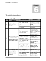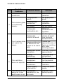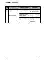
1
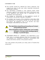
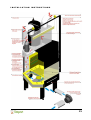
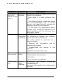
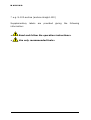
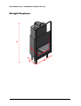
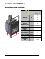
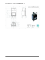
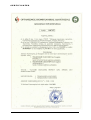
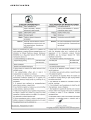
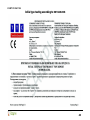
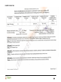
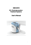
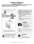
TSIAKMAKIS BROS CO - KAMINI Energy Fireplaces User’s Manual Installation & Operation 2 TSIAKMAKIS BROS CO Manual Installation, Operation & Maintenance The present installation and operation user’s manual is part of the harmonization study for the Kamini’s Fireplaces with the European directive for safety, 89/106/EEC for Construction products According to the study the appliances are able to bear the CE marking. The present manual has been composed and published by the manufacturing company: TSIAKMAKIS BROS CO - KAMINI Over ring road Olimbiados str., Evosmos, Thessaloniki, p.c. 56224, Greece Τ: +30 2310 559150 • F: +30 2310 559150 www.tzakiatokamini.gr For the publication of this manual, the company has co-operated with the technical consultants: Manual Version 1.0 Table of Contents 1 Introduction....................................................... 2 2 Installation instructions..................................... 4 3 Operation instructions..................................... 10 4 Maintenance and service................................ 22 5 Safety instructions.......................................... 25 6 Troubleshooting.............................................. 26 7 Marking........................................................... 29 8 Technical characteristics................................ 31 9 CERTIFICATES.............................................. 43 Manual Version 1.0 INTRODUCTION Chapter 1 1 Introduction D O N OT D I S C A R D T H I S M A N UA L Important operati ng and mainte nance instruct ions include d Read, understand and follow these instructions for safe installation and operation Dear customer, TSIAKMAKIS BROS CO - KAMINI highly appreciates your choice of its product, a result of systematic study and embodying long-term experience on the fireplaces field. The product of TSIAKMAKIS BROS CO - KAMINI has been designed to provide the utmost in safety, reliability and high efficiency. ► For your safety and better use of the fireplace, please read the users’ manual thoroughly before installation and operation. Pay special attention to all cautions and warnings. 2 INTRODUCTION ► This manual should be retained for future reference. We suggest you keep it with your other important documents and product manuals. ► The information contained in this manual unless noted otherwise, applies to all models and refers to the buyer-user of the appliance and anyone else is implicated on the installation and maintenance. ► Any change or intervention on the appliance except all mentioned in the present manual is forbidden. ► The installer has to apply all the installation instructions that are mentioned in the present manual, to do the first start and deliver the appliance only if its function has been thoroughly understood by the end user. The installation should be performed by well trained and qualified personnel. If the information in these instructions is not exactly followed, a fire may result causing property damage, or personal injury. ► TSIAKMAKIS BROS CO – KAMINI is not responsible in any body injury or property damage that may be caused from not applying the installation, operation, maintenance and safety instructions written in the present manual. Your new product will provide you many years of trouble-free enjoyment! 3 INSTALLATION INSTRUCTIONS Chapter 2 Installation instructions 2 WARNING! Installation MUST comply with all local regulations, including those relating to national and European standards. Chimney - introduction The chimney is the duct from where the extraction of the exhaust gas to the environment is performed at the burning devices with natural draught (fireplaces – stoves). The fireplace should fulfill the following specifications: ► The structure and the materials should be consistent with the safety rules. ► It is forbidden to pass through staircases, skylights or ventilation ducts. The passing of the chimney through the wooden roof is forbidden except if perimetrical of the duct an extra built wall with adequate heat insulation is constructed. Wooden roof components perimetrical to the chimney duct should be placed at a distance ≥70cm. ► The advisable material for the construction of the chimney is stainless steel sheet metal. In between the duct an insulating material is placed, that conserves the temperature and helps 4 INSTALLATION INSTRUCTIONS the right draught and the avoidance of liquidation of the exhaust gas in the internal of its walls. ► Every chimney should be connected to exclusively one appliance (fireplace, stove, boiler, etc). ► The internal diameter of the chimney should be consistent with the specifications of the manufacturer. ► The profile of the chimney is advised to be circular because by this way the smooth flow of the exhaust gas is assisted, the friction is eliminated, and the attachment of burn products (smog, tar) at the walls is avoided. ► In case of square or rectangular profiles, the corners should have a radius ≥ 20mm. ► The height of the chimney should be ≥ 3,5 m from the top of the device and where a corner is needed to be constructed, this should be ≥ 45 °. The common use of the same chimney with other appliances is prohibited. No passing of water pipes, air conditioning or power cables inside the chimney is permitted. TSIAKMAKIS BROS CO assumes no responsibility in case of injury or property damage if the installation instructions of the chimney are not followed. Chimney outcome (hat) The chimney ending (hat) is the device at the end of the chimney and is used to prevent the inflow of foreign bodies inside the chimney and the smooth flow of the exhaust gases to the atmosphere. The hat should: 5 INSTALLATION INSTRUCTIONS ► Be constructed of materials resistant to weather conditions (e.g. stainless steel). ► If the closest obstacle to the chimney is a tree or an element inflammable and there is a danger of fire, then the minimum distance between the chimney and this element should be ≥ 8m. ► At buildings where more than one chimney end, the height difference would be ≥ 60cm to prevent inflow of smoke. The hat of the chimney should be constructed so that it does not disturb neighboring buildings. Installation space The installation location is selected with criterion the safe use of the device, the position of the chimney and combustion air flow. The installation and use of the device in bedrooms, bathrooms and stairwells is prohibited. The use of the ventilation system while using the device in the same area is prohibited. There is a vacuum risk forcing the exhaust to get out from the device to the room. The installation of the atmospheres is prohibited. device in potentially explosive The use of the device in cooking areas where gas is used is permitted if there is ventilation. The use of camera in places where there is a risk of fire is strictly prohibited. Air supply For the operation of the device it is necessary to provide ambient air to the combustion chamber of the device. Proper 6 INSTALLATION INSTRUCTIONS air flow ensures proper combustion and provides fresh air to the ventilator, maintaining as much as possible the moisture content, reducing in that way the drying effect of the atmosphere. ► The air supply to the device should be compatible with the technical specifications of the device. ► If there is not direct air flow from the external environment then it can be obtained from adjacent areas that have contact with the outside environment via pipelines. ► The duct system should be constructed from heat resistant materials. ► On the outer side of the air supply louvers should be mounted for blocking importation of foreign bodies, and the holes should be able to deliver the required amount of air to the device. ► Make sure that during operation of the device the air flow will not stop. Power supply In case the device has a ventilator, it should be connected to the power supply in a distance ≥ 1m from the device through insulated conductor for protection. To start or stop operation of the ventilator a switch should be installed at a safe distance from the device radiation area or alternatively a wall digital controller. ► A silicone connection. cable is recommended for the ventilator ► All necessary measures to protect electrical connections from the heat emitted by the device should be taken. ► The installation of outdoor decorative lighting to the device is only permitted if the risk of fire from overheating or the short circuit of wires is eliminated. ► The facility should include grounding and electrical safety board, as defined by the technical regulations. 7 INSTALLATION INSTRUCTIONS ► The electrical connection should experienced and qualified personnel. be done only by 8 INSTALLATION INSTRUCTIONS Ventilator installation ► If hot air is transferred from the device in adjacent rooms, the length of the pipelines should be ≤ 3m with the existing pipe profile Φ125mm. ► If you wish the transfer of air at a distance ≥ 3m it is proposed to use contractions for reducing the profile Φ125mm to Φ100mm in order to maintain the initial pressure. ► The operation control of the ventilator is done by a digital wall thermostat. ► The outlets of the warm air should be separated with a distance ≥ 35cm from walls and ceilings. ► The hot air transfer ducts should be made of smooth stainless steel tube. ► To reduce heat losses it is proposed to insulate the hot air transfer duct. ► To connect the fan with the outside air it should be used a hose of a Φ125mm diameter at both entrances of the ventilator. The electric connection should be performed only by an experienced electrician. Insulation installation To eliminate the risk of possible ignition of flammable materials that are near the device and to minimize heat loss through the walls or ceiling it is suggested: ► The minimum distance between the chimney and the roof should be ≤ 30cm. The chimney should be insulated with a suitable non-combustible material which does not deform at high temperatures. In case of high risk it should also be installed additional ceiling insulation material over the device at a distance 30cm from the chimney. 9 INSTALLATION INSTRUCTIONS Chapter 3 ► If the wall is made of flammable material it should be installed plasterboard and additional ceiling insulation material between the ceiling and the plasterboard. The flammable materials that are at a radius 40cm away from the chimney should be removed. It is forbidden to install wires in the walls or ceiling at a distance ≤ 60cm from where the device is installed. Failure to follow the insulation rules may cause fire. As insulation material ceramic cotton is proposed. 3 Operation instructions 10 INSTALLATION INSTRUCTIONS WARNING! DO NOT operate fireplace before reading and understanding operating instructions. Failure to operate fireplace according to operating instructions could cause fire or injury. WARNING! High temperatures may ignite clothing or other combustible materials. Keep clothing, furniture and other combustible materials away. The fireplace is designed to work with intermittent cycle. If you expect that children may come into contact with this fireplace, we recommend locking the door of the fireplace. Operation description The environment air comes into the fireplace forced by the fan which is placed at the bottom of the fireplace. The air is pushed through the first air chamber where is preheated by the contact with the combustion chamber. The combustion is assisted by the secondary chamber, placed inside the combustion chamber, which emits more air to complete combustion and eliminate the monoxides. The air then enters the second air chamber which is placed inside the combustion chamber and is responsible for the 70% of the total heating of the air. When the air comes into the third air chamber it comes in contact with the fireplace chimney, through which hot exhaust circulates, and thus heats the air even more. The hot air comes out of the fireplace through the tubes at the top of the fireplace and the exhaust is led through the chimney to the environment. The fireplace is also equipped with: 1) a sliding door mechanism which has • Rollers with bearings • Wire for noiseless operation 11 INSTALLATION INSTRUCTIONS • Counterweight • Telescopic guides for smoother use • Wick to fully seal the door 2) Automatic damper mechanism for the exhaust gas 3) Sliding and hinged door made of ceramic glass 4) Knob for the controlled adjustment of the combustion air 12 INSTALLATION INSTRUCTIONS 13 INSTALLATION INSTRUCTIONS Wood fuel The device is designed to operate only with wood fuel. ► Properly seasoned wood is important for successful operation of your fireplace. Most woodburning fireplace problems are caused by burning wet, unseasoned wood. Seasoned firewood is wood that is cut to size, split and air dried to a moisture content of around 18%. The wood fuel supply should be carried out, if possible, during the summer months. ► The continuous use of wet wood is causing pollution to the device and ceramic glass with tobacco and tar residues and fast blockage of the chimney. ► The wood that is recommended is: beech, oak, oak. Avoid resinous wood like pine, fir, and soft resin wood such as poplar, willow because they burn quickly releasing soot resulting fast blockage to the chimney. ► Prefer wood with high consistency and weight to ensure constant and intense flame. WARNING! Risk of Fire! DO NOT burn wet or green wood. WARNING! Fire Risk! DO NOT store wood: • In front of the fireplace. • In space required for loading or ash removal. The use of wood fuel that cause small explosions is forbidden. There is risk of ceramic glass breakage and injury. 14 INSTALLATION INSTRUCTIONS Burning of painted wood, chipboard, paper, plastics is forbidden. There is risk of damaging the chimney and environmental pollution. The use of any liquid fuel is forbidden. In addition: ► Do not place the wood on the walls and the ceramic glass of the device. ► Do not stack much wood, place it in a way that it gets air and thereby proper combustion is ensured. Starting a fire WARNING! Risk of Fire! Keep combustible materials, gasoline and other combustible vapors and liquids away from the fireplace. DO NOT: • store combustible materials close to the fireplace • use gasoline, liquid fuels, kerosene or similar liquids to start a fire or during the fireplace is in use. After installing the device the first test lighting should be performed to determine the correct installation and operation of the fireplace. The first lighting should be done by the installer. 15 INSTALLATION INSTRUCTIONS For the first lighting wood fuel should be used in quantities less than 50% of the nominal consumption of the device. The first three or four fires should be of moderate size to allow the bending materials to be burned from the fireplace and paint to cure. You may notice an industrial smell during the first few fires. This is considered normal. ► Ventilate the area leaving a window open. ► If the device has a ventilator, it should be set under operation. ► Open the flue damper to a fully open position. To succeed this, close the door of the fireplace. ► Use twisted paper on the fireplace grate. ► Arrange kindling or small pieces of wood to form a ‘tent’ on the fireplace grate. ► Pre-warm the flue to establish a draught to help reduce smoke spillage during start-up. Hold a rolled up piece of burning newspaper under the flue damper for a few moments. ► Light the paper to ignite the kindling. ► Add small pieces of wood until a hot bed of coals has been established. ► Add a minimum of three average size pieces of firewood (and not more than six), placed to allow combustion air and flames between them. CAUTION! Smells and vapors released during initial operation may be irritating to sensitive individuals. Open windows for air circulation. 16 INSTALLATION INSTRUCTIONS WARNING! DO NOT throw the wood pieces with force in the fireplace. There is danger of crack or chink of the cast iron. In no case stop the fire with water. There is danger of causing damage to the device. Do not remove the burning wood from the device. There is danger of causing personal injury or fire. Grate This fireplace is designed to be used with the grate supplied with this unit. The grate may break down over time and may need occasional replacement. WARNING! Risk of Fire! Use only the factory-supplied grate: ► Keeps logs in place. ► Allows proper air circulation around the fire. Ash pan This fireplace is designed to be used with the ash pan supplied with this unit. The ash pan is used to collect the ashes, which are disposed periodically. CAUTION! The ash pan should be placed correctly, with the lower wall opposite the entrance of the air. Otherwise the entrance of air flow is restricted and traction problems are caused. Flue damper • Must be in fully open position (close the door of the fireplace) during operation of the fireplace. • Before lighting the fireplace, verify fully open position by looking up from the inside of the fireplace. 17 INSTALLATION INSTRUCTIONS WARNING! Risk of Fire and Asphyxiation! Open damper prior to operating fireplace. A closed damper overfires the fireplace and spills smoke and flames into the room. Use of the device The device you have purchased is designed to heat with minimized fuel consumption. To achieve this, you must configure and operate the device properly. Follow the instructions for proper use of the device: ► During lighting make sure the space is clean and burning remains (ash-extinguished coals) from the previous combustion have been removed. The clean device facilitates air circulation between the wood and proper combustion. ► For firelighter use some paper or ready trade kindling. Do not use liquid fuel for firelighter. Place the wood fuel in a way that reduces the risk of falling outside the device or resting on the ceramic glass. There is a risk of fire. Opening of the door ► The door should be opened slowly and be left half opened for some time (before fully open) to prevent any vacuum. ► Always use a glove that is provided with the device because many metal parts of the device develop high temperature and there is a risk of burning. ► The door should open on the side only if the ceramic glass is required to be cleaned. 18 INSTALLATION INSTRUCTIONS Do not open the door if the device operates in the same room with air suction devices (hood, ventilation) because there is a case the smoke enters to the space from the fireplace. Combustion adjustment To adjust the combustion air move the metal handle at the bottom of the device inside out. The air enters into the combustion chamber from the grate, which apart from the collection of ashes, it has the role to enter the air beneath wood fuel. Quantity of air reaches the back wall of the chamber and passes through the specially designed holes on the top of the chamber, in order the secondary gas combustion is performed and not be released carbon monoxide to the atmosphere. Damper The device has an automatic system for the opening-closing of the damper, which is performed with the opening-closing (up and down) of the door. Combustion maintenance During the night, the chamber has the capability to sustain in a minimum level the combustion. In order this can happen the following should be done: ► Place large wood in a horizontal position ► Adjust the combustion air inlet at the closed position You can open the ventilator at low volume. Throughout the combustion maintenance, the door has to be closed. 19 INSTALLATION INSTRUCTIONS Prolonged use of the device causes more tar accumulation in the chimney and at the ceramic glass demanding a more frequent cleaning. Use with door open The device operates with the door open. In this case it loses its energy properties and the combustion is done with the traditional way, with high wood consumption and low efficiency. For safety reasons, the manufacturer recommends not to leave the door open for a long period. The operation mode of the device changes and is likely that due to provocation of vacuum, for example by the sudden opening of a door, smoke goes out from the fireplace. Do not leave the device with the door open. Danger of fire resulting from sparks or coals that may fall out of the device. Make sure you do not leave access to young children, while the door is open. Stopping a fire The stopping of the fire is done only when the entire amount of wood in the fireplace is consumed. Separate the pieces of wood to stop the fire. If you wish to stop the fire immediately, you can adjust the air flow in the closed position (OFF). The fire due to lack of oxygen will stop. WARNING! DO NOT stop the fire with water. There is a danger of crack or chink of the cast iron. 20 INSTALLATION INSTRUCTIONS In case of fire use a fire distinguisher. 21 MAINTENANCE AND SERVICE Chapter 4 4 Maintenance and service For long-term economic and safe operation of the device the maintenance instructions provided in this manual should be faithfully performed. Thorough inspection and maintenance of the device should be held annually before the start of the season (autumn). ► All cleaning - maintenance work should be performed with the device stopped and the ash cleaned. ► Maintenance should be performed by qualified individuals. Except from programmed annual maintenance, additional inspections should also be performed. Cleaning of the chimney ► Remove the tar and the soot from the walls of the chimney using a special brush. Cooking food is not recommended due to the fats that stick at the walls of the chimney with possible risk of self ignition and fire. Chemicals for the separation sufficient to clean the chimney. of soot are not The accumulated tar can be self igniting. Carry out regular inspection and cleaning of the chimney. MAINTENANCE AND SERVICE Combustion chamber cleaning You should perform daily cleaning of the interior of the combustion chamber, because accumulated ash may reach up the grill and may gradually cause malfunction of the chamber. The ash pan underneath the grill should also be cleaned every day. In case the container fills the air supply to the wood may be cut off resulting poor combustion and soot accumulation in the chamber. ► The cleaning is done with the device stopped. ► Remove the ash, after making sure that there are no burning coals. ► Use a metal container for ash removal. Before emptying the container into the trash, hold it in place away from flammable materials to make sure it is fully extinguished. ► The coals that are outside from the fireplace can cause fire. The grate and the ash pan are consumables and may need replacement after 3-4 seasons of operation. Check the sale points for the supply of the spare parts. Ceramic crystal cleaning To clean the ceramic glass you should open the door to the side. Use the key provided for the side opening of the door. The cleaning of the crystal is performed when the device is stopped. Do not use materials that can scratch the glass. The engraving can be converted into crack. The crystals that KAMINI is using are ceramic with 4mm thickness, with very high resistance to thermal shock 800 °C and high elasticity. But it can be broken by a strong hit. MAINTENANCE AND SERVICE Frequency When ashes reach the bottom of the grate Action Disposal of ashes Description WARNING! Risk of Fire! Ashes could contain hot members. • Place ashes in a metal container with cap • The closed container should be placed on a non-combustible floor or on the ground, well away from all combustible materials, pending final disposal. • If the ashes are disposed at public buckets, they should be retained in the closed container until all members have thoroughly cooled. Twice a year Chimney WARNING! Risk of Fire! A chimney fire Inspection can permanently damage your chimney / Cleaning system and nearby structures. The action should be performed by a chimney sweep. • Remove the termination removing the screws • Inspect/clean chimney the interior cap by of the • Replace the termination cap After each ash removal Inspect Grate Inspect the grate and replace if: • Deformation has occurred • Is broken • Burn-through of grate bars Before every use Ceramic glass cleaning WARNING! The chamber should be completely off. Use a wet cloth made of non inflammable material. SAFETY INSTRUCTIONS Chapter 5 Safety instructions 5 Safety distances The zone around the fireplace: at least one meter around the fireplace, there must be no combustible material e.g. carpet, wooden furniture, curtains and any flammable liquids or materials igniter. ► Regulate the air exits (blinds) of the hot air so that they do not have direction on sensitive materials (curtains, curtain rods). Fire prevention ► Do not allow inexperienced persons or children to come in contact with the device without supervision. ► Inspect the chimney frequent for the accumulation of combustion residues. ► Use only recommended wood fuel. ► The use of liquid fuel is forbidden. ► Save safely the ash that contains hot coals. ► Keep the safety distances listed. ► Follow accurately the maintenance guidelines. TROUBLESHOOTING Chapter 6 Troubleshooting S/N 1 2 Start Fire Problems Can’t get fire started The chamber lets out excessive smoke when the door gets open. Possible Cause 6 Solution The wood is too wet. Use dry kindling, smaller and dryer wood. The air regulator is closed. Open the air regulator. The door opens very quickly. Open the door more smoothly letting it half open before you entirely open it. There is another suction device at the same place. Close all the suction devices. The chimney has blocked. Check and clean the chimney if needed. Increase the The profile of the profile of the combustion air combustion air inlet duct is small. inlet duct. 3 The chamber lets out excessive smoke when there are bad whether The chimney is not insulated. Insulate the chimney properly. The chimney does Raise the chimney not have the to the proper proper height. height, higher TROUBLESHOOTING S/N Start Fire Problems Possible Cause from possible obstacles. conditions. 4 5 6 7 The ceramic glass is excessively smoky. Solution Inappropriate wood. Use appropriate wood. Inappropriate convection. Chimney inspection. Wet wood. Use dry wood. Inadequate combustion air. Open the combustion air regulator. Inadequate volume of wood. Use the right volume of wood (see technical characteristics) The fireplace does Inappropriate size not warm the of device for the space. space to be warm with. Choose the appropriate size of device or combine with other warming means. Inadequate space insulation. Insulate the space appropriately. Wrong connection. Check the wire connections. Thermostat breakdown. Check or replace the thermostat. Ventilator breakdown. Check the ventilator. Power supply interruption. Check the power supply. The ventilator does not operate. The volume of the Inadequate warm air is low insulation of the and the air is not air ducts. Insulate the air ducts properly. TROUBLESHOOTING S/N Start Fire Problems warm enough. Possible Cause Solution Wrong profile choice of the air ducts. Choose the right air ducts profile. Loss of air from the air ducts. Check any damage at the air ducts. Low ventilator volume. Increase the volume of the air from the regulator. MARKING Chapter 7 7 Marking Each device is clearly and permanently marked in an accessible place where the information can be read when the device is placed in its final position, with the following information: - The name of the manufacturer - Type and description of the model to facilitate the identification of device - Nominal heat output in kilowatts, - The number of the European standard to which it is conformed - The performance of the device and the CO category The label has the following form: ΑΦΟΙ ΤΣΙΑΚΜΑΚΗ Ο.Ε., Προέκταση Ολυμπιάδος, Εύοσμος, Θεσσαλονίκη, 56224, Ελλάδα TSIAKMAKIS BROS CO, Over ring road Olimbiados str., Evosmos, Thessaloniki, 56224, Greece ΕΝ 13229:2004 Εντιθέμενες συσκευές, περιλαμβανομένων ανοικτών εστιών που καίνε στερεά καύσιμα Inset appliances including open fires fired by solid fuels Θερμική ισχύς εξόδου: ΧΧ (KW) Nominal heat output: XX (KW) Απόδοση: Efficiency: Κατηγορία CO: CO category: Τύπος/Type: X-XXΧ-Μοντέλο/Model* MARKING * e.g. S-120-arctica (arctica straight-120) Supplementary information: labels are provided giving the following « Read and follow the operation instructions» « Use only recommended fuels» TECHNICAL CHARACTERISTICS 8 Technical characteristics Chapter 8 The KAMINI fireplaces are manufactured with the most durable materials. Using advanced technology we have created a competitive end product, capable of meeting the most modern requirements. Made entirely of thick steel, they create a waterproof casing, offering 100% seal preventing the exhaust escape, which often happens in ordinary cast iron fireplaces. The fire-resistant structure of the device is composed of cast iron plates. The glass that are used are ceramic with resistance at 800 °C, very high resistance to temperature changes and to chemical reactions caused by combustion. The fireplaces are dual burning, with the capability to adjust the fire increasing or reducing the air flow of primary and secondary combustion. The main advantage of the fireplaces is the high efficiency with the low power/wood consumption that is achieved by the ability to regulate the combustion. TECHNICAL CHARACTERISTICS Straight fireplaces C F E D Β Α TECHNICAL CHARACTERISTICS Model santorini ephestus arctica Straight – 75 Straight - 90 Straight -120 800 970 1280 520 600 580 1700 1700 1620 740 900 1200 420 500 480 800 800 765 mm ∅250 ∅250 ∅250 KW 24 34 40 Efficiency % 70 68 72 Fuel consumption Kg/h 6,7 – 7,0 8,9 – 9,3 11,4 – 11,6 Flue gas mass flow g/sec 26 32 32 Content of CO % 0,26 0,32 0,31 Mean gas temperature °C 318 314 385 Wood Wood Wood External dimensions (mm) Internal dimensions (mm) Flue coupling dimensions Nominal heat output Fuel Length Α Depth Β Height C Length D Depth E Height F TECHNICAL CHARACTERISTICS Β Α TECHNICAL CHARACTERISTICS Three sided fireplaces C F E D Β Β Α DΑ TECHNICAL CHARACTERISTICS Model External dimensions (mm) Length Α Depth Β Height C Internal dimensions (mm) Length D Depth E nisyros oxygen vesuvios Three-sided – 60 Three-sided – 75 Three-sided - 90 680 800 970 560 695 715 1400 1700 1700 600 740 900 460 580 610 Height F 650 mm ∅200 ∅250 ∅250 KW 17 24 30 Efficiency % 70 70 67 Fuel consumption Kg/h 4,9 – 5,0 6,7 – 7,0 8,9 – 9,3 Flue gas mass flow g/sec 20 26 30 Content of CO % 0,36 0,26 0,32 Mean gas temperature °C 278 318 310 Wood Wood Wood Flue coupling dimensions Nominal heat output Fuel 820 TECHNICAL CHARACTERISTICS TECHNICAL CHARACTERISTICS Quattro fireplaces C F E Β D Α TECHNICAL CHARACTERISTICS Model External dimensions (mm) Internal dimensions (mm) Flue coupling dimensions Nominal heat output nemesis erevos etna Quattro - 50 Quattro - 75 Quattro - 90 Length Α 580 750 910 Depth Β Height C Length D Depth E Height F 580 610 1700 1700 1700 500 740 900 500 505 505 800 800 mm ∅200 ∅250 ∅250 KW 18 24 28 % 70 70 69 Kg/h 4,9 – 5,6 6,7 – 7,0 8,0 – 8,7 g/sec 23 26 34 Content of CO % 0,25 0,26 0,32 Mean gas temperature °C 279 318 318 Wood Wood Wood Efficiency Fuel consumption Flue gas mass flow Fuel TECHNICAL CHARACTERISTICS TECHNICAL CHARACTERISTICS Water jacket (Boiler) fireplaces Model Voda Boiler - 75 External dimensions (mm) Length Α Depth Β Height C Internal dimensions (mm) C F E D Β Α Length D Depth E 870 640 1700 720 550 Height F 870 mm ∅250 KW 30 Efficiency % 70 Fuel consumption Kg/h 8,4 Flue gas mass flow g/sec 28 Content of CO % 0,37 Mean gas temperature °C 339 Flue coupling dimensions Nominal heat output Fuel Wood TECHNICAL CHARACTERISTICS CERTIFICATES Chapter 9 CERTIFICATES 9 TSIAKMAKIS BROS – KAMINI company has conformed with all the procedures for fireplaces certification so with compliance with European safety standards (CE) so with patent in their operations. The relevant certificates are presented. CERTIFICATES Patent certificate CERTIFICATES CERTIFICATES Manufacturer Declaration of Conformity CERTIFICATES CERTIFICATES Initial type testing according to EN 13229:2006 48 CERTIFICATES 49