1
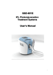
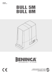
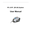
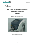
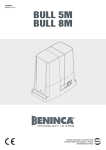
User’s Manual IPL530 IPL Treatment System User’s Manual Page 1 User’s Manual © 2008 GUANGZ HOU BECO ELECTRONIC TECHNOLOGY CO., LTD. All rights reserved. Reproduction of this User’s Manual in any form, including excerpts, requires permission from GUANGZ HOU BECO EL ECTRONIC TECHNOLOGY CO., LTD. All rights are reserved in the event of the grant of a patent or the registration a utility model or design. Manufacturer GUANGZ HOU BECO ELECTRONIC TECHNOLOGY CO., LTD. Page 2 User’s Manual Contents Using this User’s Manual..........................................................................................................5 Chapter 1 Preface......................................................................................................................6 1.1 Overview............................................................................................................................6 1.2 Device Brief Introduction....................................................................................................6 1.3 Device Structure ................................................................................................................6 1.4 Medical Use-Application Areas ..........................................................................................7 Chapter 2 Safety........................................................................................................................8 2.1 Introduction........................................................................................................................8 2.2 Responsibilities of User .....................................................................................................8 2.3 User Training .....................................................................................................................9 2.4 Explanation to Patients ......................................................................................................9 2.5 Optical Safety ....................................................................................................................9 2.6 Electrical and Equipment Safety......................................................................................10 2.7 Fire Prevention ................................................................................................................10 2.8 System Safety .................................................................................................................10 2.9 Safe Classification of Equipment .....................................................................................10 2.10 Lable of Equipment........................................................................................................11 Chapter 3 Description .............................................................................................................13 3.1 Parts and Control.............................................................................................................13 3.2 Accessories: ....................................................................................................................14 3.3 System Software..............................................................................................................16 3.4 Environment Requirements .............................................................................................16 Chapter 4 Installation..............................................................................................................17 4.1 Equipment Detailed List...................................................................................................17 4.2 Installation Requirements ................................................................................................17 4.3 Installation .......................................................................................................................19 4.4 Move................................................................................................................................23 4.5 Transport and Storage Procedure....................................................................................23 Chapter 5 Operation................................................................................................................24 5.1 Software Operation Explanation ......................................................................................24 5.2 Treatment ........................................................................................................................30 Chapter 6 Maintenance ...........................................................................................................33 6.1 Cleaning Main Host .........................................................................................................33 6.2 Cleaning Sapphire Crystal ...............................................................................................33 6.3 Replace IPL Treatment Handpiece ..................................................................................33 6.4 Refilling Water Supply .....................................................................................................33 6.5 System Trouble Shooting.................................................................................................34 Chapter 7 Clinical Application……………………………………………............…………….....35 7.1 Training…………………………………………………………………………………..……....33 7.2 Application .......................................................................................................................35 7.3 Treatment Must Know......................................................................................................38 Page 3 User’s Manual 7.4 Preoperative Preparation.................................................................................................38 7.5 Untoward Reactions ........................................................................................................39 7.6 Treatment Parameters .....................................................................................................40 7.7 Procedure ........................................................................................................................41 7.8 Post Operative Nursing Care...........................................................................................40 7.9 Advantages of IPL Treatment...........................................................................................43 Chapter 8 Parameters Selection ............................................................................................44 8.1 Treatment of Pigmented Lesions .....................................................................................44 8.2 Treatment of Vascular Lesions & Acne ............................................................................45 8.3 Hair Removal...................................................................................................................47 8.4 Photorejuvenation & Deep Scars.....................................................................................48 Chapter 9 Specifications ........................................................................................................51 Fitzpatrick Classification of Skin Types ................................................................................53 Annotations..............................................................................................................................54 Page 4 User’s Manual Using this User’s Manual This User’s Manual is divided into the following sections: Section Contents Preface Safety Description Installation Operation Maintenance Clinical Application Parameters selection Specifications Brief technical overview and Medical use General safety precautions when operating the device Description of the components and controls Introduction of the installation and transport procedure Operation of the device Maintenance information including application range、treatment process and side effect Basis of parameter selection and treatment evaluation Brief overview of the specifications Pay Attention to Warnings, Cautions and Notes WARNING Warning means that not following instructions properly or ignoring them completely can endanger patients and/or operators. CAUTION Attention means that not following instructions properly or ignoring them completely can damage the unit. NOTE Notes provide additional information. Page 5 User’s Manual NOTE Read the user’s manual prior to operation! Chapter 1 Preface 1.1 Overview Intense pulsed light (IPL) is a type of intensive, broadband, coherent light source which has a wavelength spectrum of 430 nm -1200 nm. With these special properties, the IPL has a wide application in non-ablative therapies based on theory of human skin tissue's selective absorption and photothermolysis of light sources. Meanwhile, IPL treatment is more effective, with no downtime and can make the patients get recovered more quickly than conventional therapies. 1.2 Device Brief Introduction Model Name: IPL530 Product Name: IPL Treatment System Figure 1.1 shows the device. Figure1.1 IPL530 IPL Treatment System 1.3 Device Structure This device is composed of three parts: (1) main unit, (2) control panel, and (3) the IPL treatment handpiece The control panel includes the True Color 7.0” LCD Touch screen, the power switch and emergency shut off switch. The LCD Touch screen shows the work mode and the parameters of the system. Page 6 User’s Manual 1.4 Medical Use-Application Areas 1. Permanent hair removal 2. Skin rejuvenation 3. Reduction of pigmented lesions 4. Wrinkle removal 5. Acne Therapy 6. Freckle, vascular lesions and facial blemish removal Page 7 User’s Manual Chapter 2 Safety 2.1 Introduction This chapter describes the proper use of the IPL Treatment System . Each operator must have read and understood the User’s Manual completely prior to starting the Device. 2.2 Responsibilities of User WARNING This device may cause thermal injury if used improperly. Medical personnel must familiarize themselves with the devices safety instructions and operational procedures prior to use. Before each treatment, the user must check the functional performance of the device in order to rule out any risk to patients or third parties. if the devce is used in conjunction with peripheral units, the User’s Manuals for the peripheral units must also have been thoroughly read and understood. 2.2.1 Safety Measure The IPL is designed to prioritize the safety of the patient and medical personnel. The following are its parts of safety measures: A. Upon switching on the system, the processor first undergoes a self-diagnostic program. The processor will then examine the system automatically and continuously during the entire treatment procedure. B. Use the Emergency Cut Off Switch (red button) to turn the power off in case of an emergency. C. Remove the Key when not in use to prevent unauthorized access to the device. 2.2.2 Safety Warning Only personnel trained by the distributor are authorized to maintain the inner workings of this device. Any manipulation to the system may cause damage to the device and will void its warranty. Page 8 User’s Manual 2.3 User Training WARNING The intense light delivered by this device may cause serious injury if handled improperly. All personnel using this device must remain vigilant and utilize safety facilities. The IPL Treatment System require special expertise and care in its handling and use. Only persons who have received appropriate handling training on the device, taking into consideration operating instructions, and who are familiar with its therapeutic effect and possible risks are permitted to use the laser unit. Untrained or unqualified operating personnel are not permitted to operate the IPL Treatment System under any circumstances whatsoever. GUANGZ HOU BECO ELECTRONIC TECHNO LOGY CO., LTD. offers comprehensive training courses for the IPL Treatment System . Each user must have read and understood the User’s Manual completely prior to starting the IPL Treatment System . Patient’s safety mainly depends upon a well-trained operators and a suitable treatment room. The attending operators must inform the patient all inherent risks with the use of this device. The success of the treatment depends largely on the user’s experience and knowledge of the biophysical connections. 2.4 Explanation to Patients The treatment process must be explained to the patient. The patient must give written-consent to the treatment. 2.5 Optical Safety All personnel (including the patient) should wear the protective glasses; opaque eye shield for the patient and filtered 200 nm – 1400 nm for the operators. The goggles / glasses provided with this unit are manufactured specifically for the 400 nm to 1200 nm wavelength produced by the IPL unit. Do not substitute treatment / safety glasses with other types of tinted eyewear which may not meet the specific safety requirements of the unit. Note: Gauze, eye-shield and tarsi are all effective in the protection for the eyes 2.5.1 Intense Light Warning The intense light may damage the eyes. Please observe caution at all times. Avoid looking directly into the sapphire crystal during operation even if wearing the protective goggles. When not in use keep the treatment handle on its carriage and keep the device on standby or simmer mode. Page 9 User’s Manual 2.5.2 Treatment Room The treatment room should be clearly marked to prevent unnecessary access by other personal during the procedure. 2.6 Electrical and Equipment Safety The unit uses 200V~260V 50/60Hz; 90V~130V 50/60Hz single-phase power supply. Its capability should be no less than 2000W. Use a 10A (200V~260V 50/60Hz); 20A (90~130V 50/60Hz) single-phase three-wire outlet at an international level. This device connects the ground through three lines, connecting the ground well is important to the operation safety The high voltage inside the device is very dangerous. The maximum charged volts of energy stored in the capacitor is 450V. When the device is switched off, the maximum energy remaining in the capacitor is 1000J as a residue voltage. It is not advised to open the cover. This will result in an electrical shock. Do not open the control or rear panel even if the unit is switched off. Only authorized personnel may repair or maintain the IPL unit. Tampering with the unit will void its warranty. 2.7 Fire Prevention The intense pulsed light device generates thermal energy. Avoid using combustible material such as acetone or alcohol in the operative field. If alcohol based products are used to disinfect the IPL device, ensure that the alcohol has completely evaporated prior to operation. 2.8 System Safety The key switch is used to turn the unit on and off. Please remove the key when the unit is not in use to prevent unauthorized access. The emergency cut off switch is used to shut down the device in case of any emergency. After engaging the emergency shut off button, turn the device off by rotating the key in a counterclockwise direction. Rotating the emergency cut off switch in the direction indicated by the white arrows will release the button. A 10-ampere circuit breaker is installed behind the device adjacent to the power cord. Loads in excess of 10 amperes will trip this switch. Simply moving the switch upward will restore power to the system. A self-diagnostic program then initializes the system and will continuously monitor the circuitry during operation. 2.9 Safe Classification of Equipment The equipment safe classification: Electric shock protection — class Ⅰ,type BF equipment; Page 10 User’s Manual Corrosion preventing liquid: commonness; Can't use this IPL system in the environment where the combustibility, anaesthetic and the air or carbon monoxides mixture exist. Operating mode:Consecution. 2.10 Lable of Equipment 1. NAME PLATE (Model) LABEL : Position: back side Model Name: IPL530 Product Name: IPL Treatment System Power Supply: 220V, 50/60Hz, 10A GUANGZ HOU BECO ELECTRONIC Technology Co., Ltd. TEL: +86-020-81622619,81622627 FAX: +86-020-81622610 Before operating and maintaining the IPL Treatment System , please read user’s manual in detail 2. WARNING LABEL : Position: front side WARNING PROTECTIVE EYEWEAR MUST BE USED RISK OF EXPLOSION IF USED IN THE PRESENCE OF FLAMMABLE ANESTHETICS 3. CAUTION LABEL : Position: cover back side Page 11 User’s Manual 4. CAUTION LABEL : 5. DANGEROUS VOLTAGE WARNING LABEL : Position: inside Page 12 User’s Manual Chapter 3 Description This chapter will introduce the main parts of the system, the accessories and the process of installation & debugging. 3.1 Parts and control The IPL Treatment System is composed of the following parts: el trol pan 1. Con 2. IPL Treatment handpiece 3. Main unit Figure 3.1 Main parts of the IPL Treatment System 1. Control panel 2. IPL Treatment handpiece 3. Main unit 3.1.1 Main Unit The Main unit is the integral part of this system; it consists of the following parts. 1. The Power supply module: regulates electrical supply to the entire system. 2. The Control module: Regulates and coordinates the various components of the system for optimum performance. 3. The display module: Displays various information of the system and accept users instruction. 4. High current capacitors: Delivers adequate electrical energy to guarantee sufficient power during operation. 5. Cooling system: Maintains a stable thermal environment for optimum performance. Page 13 User’s Manual CAUTION Only engineers certified by KES are authorized to service and maintain this device. 3.1.2 Control Panel Operation of this device is done through the control panel. It includes the following parts: Key switch: Used to turn on and off the power supply. (Clockwise to turn on and counter clockwise to turn off) Emergency turn off switch: The red button found in the front panel of the device is used to immediately shut off the device’s power supply in case of any emergency. Pressing this button will cut off the power supply to the whole system. Rotating the button in the direction of the arrow printed on its surface will disengage the button and will reengage the power supply. When this button is engaged, remember to turn the key switch to the off position afterwards. The Liquid Crystal Display (LCD) shows the operational settings and adjustments as well as system status is displayed on the screen. 3.1.3 IPL Treatment Handpiece The IPL handle consists of a (1) Cable housing: this contains the power cable, liquid coolant tubing, control data cable; (2) IPL head: this houses the control switch, flash lamp, sapphire crystal, filter piece and electronic semi-conductor cooling system. Pressing on the trigger on the IPL treatment head discharges the flash lamp at the settings as displayed on the control panel. Pushing down the foot switch like-wise discharges the device (on selected models only). The supplied sapphire crystal measures 12mm x 35 mm and is superior in both clarity and longetivity, thereby increasing both the efficiency of the flash lamp and lifespan of the treatment head. It is very important to keep the sapphire crystal clean. Make sure to clean this with a soft cloth after each treatment. A disinfectant such as alcohol can be used between treatments. Dried gel on the crystal filter will reduce efficiency of the flash lamp. Replace the plastic guard over the filter to prevent damage. In the event that the sapphire crystal is damaged (i.e. nicked or cracked) contact your dealer immediately. 3.2 Accessories: The accessories of this device include: Filters Handpiece support (assembled in device) Protection glasses (operator) Protection goggles (patient) 5pcs 1pc 1pair 1pair Page 14 User’s Manual Users manual Drainage hose Funnel Power cable O-Ring for faucet Key 1pc 1pc 1pc 1pc 1bag 2pcs 3.2.1 Filter Standard Spectra Optional Spectra 430 -1200nm Application Areas vascular & acne & pigment 480 -1200nm vascular, pigment, photo rejuvenation 520 -1200nm vascular, pigment, photo rejuvenation 530-1200nm vascular, pigment, photo rejuvenation 590-1200nm vascular, pigment, photo rejuvenation 640 -1200nm hair removal 690 -1200nm hair removal 755 -1200nm hair removal 3.2.2 Protection Glasses One pair of protective glasses are provided with the device. The opaque glasses are to be worn by the patient and the filtered 200-1400 nm glasses are to be worn by the operator. Despite wearing the protective glasses, avoid staring directly into the intense pulses of light during the treatment. Only personnel wearing protective glasses may be allowed to observe the treatment. 3.2.3 Light-coupling Gel The light-coupling gel is used to maximize the conduction of light from the flash lamp to the skin. The light-coupling gel must be clear/transparent and not colored/tinted. Colored gels absorb light therefore reducing the effectiveness of the treatment. The light-coupling gel must be chilled but not frozen. Frozen gel diffuses the light emitted by the flash lamp reducing its efficacy. Light-coupling gels must be non-alcohol based. The IPL produces considerable heat; flammable material must be kept clear of the treatment area. Please order the light-coupling gel in the local market. 3.2.4 Order Accessories A complete set of accessories is included with this device when delivered. Additional accessories may be ordered through your authorized distributor. This device is very sensitive. Accessories and spare parts not provided by your authorized distributor must never be used with this device. Doing so will void your warranty. Page 15 User’s Manual 3.3 System Software The software of the IPL mainly has four functions: 1. Allow the doctor to choose the best characteristic parameters for the patients according to the concrete diagnosis. 2. Control the working process of the system, in order to prevent unexpected trouble. 3. Examine the system energy . 4. Choose the treatment ranges. 3.4 Environment Requirements Working temperature scope Relative humidity scope Atmospheric pressure barometric : +15~+30°C : 30%~80% : 86kpa -106kpa The store environment temperature : +5°C ~+55°C Power supply : 230V AC , 50/60Hz, 10A; or 115V AC , 50/60Hz, 20A Page 16 User’s Manual Chapter 4 Installation The process of installation includes: (Performed by an authorized technician only) 1. Unpacking the device. 2. Staying the device for one day, in order to avoid destruction by high humidity during long distant transportation. 3. Assembly of its components and ensure that all connections are firmly in place. 4. Fill the water tank with distilled water only. 5. Installation treatment handpiece and connect the power supply 6. Switch on the device and test all functions / parameters of the system 4.1 Equipment Detailed List The following is the detailed list of equipment of this device:: ¾ Main host ¾ The IPL treatment handpiece 1pcs (12mm x 30mm) ¾ Handpiece support(assembled in device) ¾ Protective glasses ¾ Protective goggles ¾ Power cable ¾ Foot switch ¾ Funnel ¾ Plastics hose ¾ Key ¾ O-Ring ¾ Stainless water faucet ¾ The plastics cover of light head crystal ¾ User’s manual 4.2 Installation Requirements Before unpacking the IPL Treatment System , ensure that working environment conforms to the requirements of this section. Before assembly of the device’s components, ensure that high humidity is cleared away by opening the packing and staying the device for one day. 4.2.1 Location Requirements The device should be positioned in an area with adequate ventilation away from devices that produce heat (i.e. refrigerator). Page 17 User’s Manual 4.2.2 Electrical Requirements Before the IPL leaves the factory, it has already been marked the local rated voltage according to the customers’ request. It corresponds to the electricity requirement as follows: AC230V±10 %,10A,50/60Hz. or AC115V±10 %,20A,50/60Hz Input electric current can’t have momentary change, electric voltage or electric current peak、 sink. It is recommended that this device use a dedicated power supply with its own circuit breaker. CAUTION Ensure that the electric voltage rating of this instrument (AC230V or AC115V refer to system labeling) matches the electric voltage of the outlet. 4.2.3 Environment Requirements Air quality:No caustic particle (such as acid) in the air, which can damage the electric wire, the electric component and optical component surfaces. The dust in the air should be as little as possible, or it can absorb the energy of light and be heated up. When the dust falls on the surface of the filter, it may damage the filter. Metal particles also could damage the electric component. Temperature: The IPL system has an optimal working temperature between 15°C~30°C. Relative humidity should not be over 80%. The working power of this device is about 2 KW. It would be best that the IPL unit be installed in an air-conditioned room where the relative humidity and temperature can be maintained at optimal levels. Page 18 User’s Manual 4.3 Installation 1) The device should be placed in a room with an indoor temperature of 15~30°C; the humidity should not be higher than 80%. Operating or treatment rooms must be kept clean of all times. 2) Turn on the Infusion/drain tap then put on the tap connector into the infusion tap from accessories bag and unscrew the ventilation screw caps. (According to the following figure) Figure 4.1 Figure 4.2 3) Infuse distilled water until the water level reaches 90% level of the water observation window. Figure 4.3 Page 19 User’s Manual 4) 5) 6) 7) 8) Ensure that the key is in the off position and that the emergency cut off button is not engaged. If it is engaged, release it by rotating the button towards the direction of the arrow indicator. Attach the power cord and attach the foot switch cord. Switch the circuit breaker to the “On” position Switch the device on by turning it in a clockwise direction. At this time water circulation and the cooling system starts automatically. Observe whether water circulation runs well or not. After cooling system runs for at least 1 minute, the water has slided into the cooling system and then turn the device off. If the system sounds beep and show “water current error”, then you need to move out the bubble air from the system. In the stage: switch off the power, take off the protection plug for water conduit (as Figure 4. 4), then switch on the power, meanwhile the water will spout out from the front of water conduit . Moreover, If a leak is observed, turn the unit off , then take off the protection plug of water conduit and check whether the O-Ring for faucet is likely to be lost. If the O-Ring is lost , user should take out the O-Ring from accessories and push into water conduit. 9) After cooling system runs for at least 1 minute, the water slide into the cooling system and then turn off the power. 10) If the water circulation run well. Then switch off the system. It means you can fully assemble system with handpiece, screw on the infusion cap and ventilation caps. 11) When installing a new treatment handpiece or switching between treatment handpiece, place the treatment head lower than the main host in order to remove bubbles from the treatment head, Then turn the device on. Let the water circulate for at least 1 minute before proceeding with the treatment. 12) Install multi-treatment head (5 in 1 by changing filters) for single head models (IPL530). According to the following figure, pull out the protection plug for water conduit first. Connector of Handpiece Figure 4.4 Page 20 User’s Manual 13) Plug the handpiece connector firmly and properly to avoid the water circulation problem as the following figures. First plug the right pin directly to the right socket, then insert the left one. (Figure 4.4) Figure 4.6 Figure 4.5 14) When pulling out the hand piece, press the two srew caps of the hand piece as the following figures. Figure 4.7 15) According to the following figure 4.8 changeable of the various wavelength by 420, 530, 640 ~1200nm filter of KES standard specification for spot size: 12x30mm of IPL530. Figure 4.8 Page 21 User’s Manual Please pay attention to that the angle of filter should match that of slot as follows: slot filter 16) Replace the treatment head or replace water 1. When replacing the treatment head, drain the remaining water in the previous handle. Pay particular attention as not to spill any water on the electronic terminals. Wipe off any spilled water with a soft absorbent cloth. 2. Replace water every 2-3 months, please carry on according to the following steps strictly. z Disconnect handpiece. But you need to keep the above part (as Figure 4.4) on the water conduit of handpiece. z Turn on the infusion/drain tap and unscrew the ventilation screw caps. (as Figure 4.1) z To drain excess water from the cooling tank. Turn on the drain tap, insert the drainage hose supplied then open the ventilation screw cap. Fasten all screw caps firmly. CAUTION 1. 2. 3. 4. Only distilled water is to be used in the cooling system. When using the system for the first time, rinse the cooling system with distilled water. Ensure that the water level is adequate before treatment to prevent over heating. Distilled water is added periodically specially when working in warmer climates and when the treatment handpiece are changed often. 5. Make sure that the treatment head is firmly secured and the screw caps are firmly screwed into place prior to operation. Page 22 User’s Manual 4.4 Move If the device is to be moved within the general area, 1. Turn the device off 2. Put the treatment head on the support 3. Pull out the power cable 4. Relocate the unit (Avoid tilting the device) CAUTION If the instrument is to be moved outside the hospital, please contact your dealer. 4.5 Transport and Storage Procedure 4.5.1 Procedure 1. The cooling water in the instrument should be let out and cleaned during storage and transport. 2 .The device should vertically be installed in the outer packing box during transport. The instrument is fixed on the base >550mm×490mm×430mm so that the wheels of the instrument will not glide. 3. There are waterproof and soft gasket material in the outer packing box of the instrument and handle with care which the instrument should be supported by natural damage. The markings such as “Handle with care”, “No wetness”, “up” should be on the box. 4.5.2 Environment 1. Environment temperature range: +5 ℃~ +55 ℃ ; 2. Relative humidity range: 30%~80%; 3. Atmospheric pressure Range: 86kpa -106kpa. Page 23 User’s Manual Chapter 5 Operation This chapter will describe the operating procedure of the IPL Treatment System . WARNING 1. WARNING: HIGH VOLTAGE: please ensure that all panels are secured prior to operation. 2. Place the IPL treatment head on its support when on standby mode. 3. All personnel in the treatment room must wear the protective filtered glasses supplied. 4. Make sure the patient is wearing the opaque protective goggles prior to treatment 5. Avoid looking directly into the intense light during the treatment even if you are wearing the protection glasses. 6. Do not point the treatment head outside the treatment field. 5.1 Software Operation Explanation 1. Welcome Note Treatment Mode Figure 5.1 Turn the unit on by turning the key switch in a clockwise direction. The screen will show the welcome interface and will undergo a systems check-up diagnostic program. (See figure5.1) The program will then enter the Treatment Mode Selection Menu. Treatment Mode Selection Page 24 User’s Manual Once Treatment Mode Window: shows the current treatment mode. z Once in the Treatment Modes Selection Menu, touch one of Treatment Mode between ( Hair Removal /Skin Rejuvenation/Pigmentation Therapy/Vascular Therapy/Acne Therapy/Breast Lift up) on the screen to make a selection of your treatment. Once in the selected treatment menu (i.e. Hair Removal mode), as highlighted on the screen. (see figure 5.1). 2. Parameter Setting Menu( see Figure 5.2) z z z z z z IPL Energy Output window: displays current energy output setting. Treatment Parameters: shows the current accepted treatment parameters. System Information window: shows the available control options. Any warnings or system errors are displayed here. Treatment Counter: displays the total number of shots by the specific treatment hand piece / total number of shots for this specific treatment Parameters Storage: displays three different treatment parameters saved automatically. Exit: touch the “Exit “button to return to previous Menu. Parameters Storage IPL Energy Output Treatment Parameters Exit System Information Treatment Counter (Figure 5.2) NOTE For systems IPL530 with interchangeable filters, turn the system on then select the proper filter (i.e. 640 nm for hair removal) and gently insert it unto slot of the treatment head. Then select the desired treatment. Replace filters only when the unit is in standby simmer mode. 3. Treatment Parameter Setting Parameter setting ranges from Pulse Duration, Pulse Delay, Pulse Number, to Pulse Interval. The max Pulse Number is 6, max Pulse Duration: 10ms, max Pulse Delay Time is 100ms. Page 25 User’s Manual Touch each figure will turn to the selected parameters, touch again will allow you to modify the selected parameters. Touch the “Enter “button to return to previous Menu. (Figure 5.2) 1) Pulse Number: from 1 to 6 (the interface can only display 3 items) 2) Pulse Interval: from 1 to 4S 3) Pulse Duration: from 1 to 10ms (after the second Pulse Duration, it shows only the max of 5ms) How to adjust Pulse Duration and Pulse Delay Take Pulse Duration for exmaple, touch the figure and it turns to be highlighted, with “Up and Down” button showing on the interface. Touch “Up and Down” button to adjust the Pulse Duration, and touch the figure again to make the adjustment. (Figure 5.3) NOTE A list of suggested parameters is provided with this manual. Always refer to this set of parameters prior to treatment. Please remember that these data are used mainly as a guide and are not absolute. Page 26 User’s Manual 4. Power / Fluence Selection (IPL & RF) In the Treatment Menu Screen, the power / Fluence of the system can now be adjusted by pressing the “Up and Down” buttons. (Figure 5.4) z IPL Energy Output window: displays current energy output setting. (1~50J/cm2) When the figure is highlighted with blue color, it displays IPL energy. The energy output or fluence is the total energy measured in Joules/cm2. Because of the small spot size (12 x 30 mm), the scattering effect of light is minimized. The higher the fluence the greater the amount of energy is delivered to the skin. The fluence can be increased or decreased at the Treatment Menu by depressing the: Up or Down button” respectively. 5. Treatment Interface Page 27 User’s Manual (Figure 5.5); Pulse Cycle or Frequency (Pulse Interval) Is the duration between pulses. The frequency is adjusted between 1 to 4 seconds. Pulse Number or Times: the fluence can be divided from 1 up to 6 pulses. Because the power of the system can be divided into a series of pulses (unlike the previous generation of IPL units), the treatment is less painful and more effective in patients with darker skin types. Pulse Width or Pulse Duration: is the length of time that the skin is exposed to the pulse of light. The larger or darker the lesion, the longer it will take to heat up as compared to smaller lesions or those with less pigment. Pulse Delay is the resting phase between pulses (i.e. between first and second pulses) this delay or rest phase allows the surrounding normal epidermis to cool down prior to initiating the next pulse. First Second First Delay Third Second Delay First Repeat Delay Pulse Interval Figure 5.6 NOTE Page 28 User’s Manual A list of suggested parameters is provided by apolo territory distributors. Always refer to this set of parameters prior to treatment. Please remember that these data are used mainly as a guide and are not absolute. 6. System Information System Information window: shows the available control options. Any warnings or system errors are displayed here. Cooling/Temperature Adjustment (Figure 5.7) 7. Exit After completing the treatment (Ready), place the unit on simmer / standby mode by pressing the “Standby” button. This will terminate the active treatment phase and disengage the flash lamp. Please note that by going on Standby mode, the service lifetime of the treatment handle is maximized. Touch the “EXIT” to return to the Main menu. Then you may switch off the power system now. NOTE After completing the procedure, place the system on standby by pressing the “SIM” button This will allow cooler operating temperatures and will also prolong the life of the flash lamp. Page 29 User’s Manual 8. System Settings. Control Options (Figure 5.8) In the Systems Settings Mode, there are three selections that can be adjusted. (1) System Language Setting: set the language of the system to multi-language; (2) Key Tone Setting: set the tone to either ON or OFF; (3) Calibrasion; set the center point of the interface. Page 30 User’s Manual 5.2 Treatment 1. Select the filter (i.e 640 nm for hair removal) for changeable handpiece units (IPL530), plug the filter (according to figure 4.8) firmly and properly prior to turning the device on. 2. Turn the device on by turning the key switch in a clockwise direction. The screen will show the main menu and will undergo a systems check up diagnostic program. (See figure5.1) After select desired treatment mode by touch of screen ,the program will then enter the Treatment Mode Selection Menu 3. Touch figuers on the screen to modify the parameter settings (as mentioned in figure 5.2 and 5.3). After the desired parameters have been settled, the Energy output and RF power output (for handpiece spot size 12x30mm) can be adjusted by touching the “UP” and “DOWN” buttons. If you don’t use RF function with your treatment then you may close RF power output function by making it to gray mode. 4. Touch the “Ready” to simmer and ready for treatment. 5. Observe proper optical safety by wearing the safety goggles provided with this device. (Opaque for the patient and filtered for the operator) 6. Apply a thin layer (2-3 mm) of cold gel over the entire treatment area. While exerting light pressure, approximate the treatment head perpendicularly over the treatment area. And press the Trigger button on the treatment handle to begin treatment. 7. Evaluate the treatment area for any untoward side effect such as pain. During treatment the parameters can be adjusted as to your requirements. 8. Before moving on to the next treatment area, gently remove the gel from the previously treated area and apply a cool compress (cold gel pack). 9. After treatment, copy the treatment parameters to the patients record sheet and place the device on Simmer or Standby Mode by depressing the “Standby” key. 10. Turn off the device by turning the key counter clockwise. Clean the IPL treatment head with a soft cloth. Then sanitize the treatment head with alcoholized cotton balls. 11. Replace the treatment handle on its carriage and unplug the device. NOTE Disinfect the treatment head after each treatment. Schedule your patient for subsequent follow up to evaluate future treatment. At the end of clinic hours, remove the IPL handle cover and remove any gel that may have accumulated with a soft damp cloth. Page 31 User’s Manual WARNING 1. Do not point and operate the device elsewhere other than the intended treatment area. 2. The light generated by this device is very intense. Exercise Optical safety measures by wearing the protective goggles. Avoid looking directly into the treatment area during operation even when wearing the goggles. Page 32 User’s Manual Chapter 6 Maintenance This chapter describes the regular maintenance that can be performed by the owner. Authorized personnel must do any other maintenance work not described in this chapter. System troubleshooting is also enumerated in this chapter. WARNING Before any maintenance work turn the power off and unplug device. Failure to turn off the power may cause an electric shock, damage to the device and bodily injury. Never attempt to remove the back panel or device casing. Unauthorized tampering with the internal system of the devices will automatically void the warranty. 6.1 Cleaning the Main Host The main host casing or body must be clean with a soft damp cloth. A mild detergent may be used but be cautious as not to let liquids from entering the units internal mechanism. 6.2 Cleaning the Sapphire Crystal The Sapphire crystal must be kept clean at all times. Always use a soft damp cloth or wet cotton balls. Sanitize the treatment head with alcoholized cotton balls. 6.3 Replace the IPL Treatment Handpiece Each IPL treatment handpiece has a limited service life. After consuming 60,000 cycles, the treatment handpiece must be replaced. You need to call your re-seller or dealer for this replacement. 6.4 Refilling the Water Supply Observe the water level through the water observation window at the rear of the unit. The water level is best maintained within the midpoint of this window. Distilled water can be added by following the instructions seen in “Section 4.3 Installation”. Page 33 User’s Manual 6.5 System Trouble Shooting Check power cable Check circuit breaker / fuse Check key switch No power Disengage the emergency cut off switch by rotating towards the direction of the arrows indicated Notify your distributor Key pads are none responsive Please contact the dealer. System failed to initialize Not enough power, please check main power supply. Please contact the dealer. The treatment head / flash lamp has reached its maximum life span (40,000) shots. Replace the treatment head Malfunction of flash lamp on the IPL treatment head The IPL treatment head is leaking The IPL treatment head is probably damaged, please change the IPL treatment head or contact the dealer. O-Ring for faucet is likely to lose, Pull out the treatment handpiece, then take out O-Ring from accessories and push into water conduit. The IPL treatment head is probably damaged, please change the IPL treatment head or contact the dealer. The system is designed for continued used for up four hours in optimal environmental temperature and humidity. The treatment handle is warm Always place the system on standby mode while awaiting treatment. The system might have been left on for an extended period. Turn the unit off, let it cool down for half an hour then re- start Contact the dealer. The power of The IPL treatment head has weakened The treatment head has nearly reached its maximum life span (60,000 shots) the fluence can be adjusted by a few joules to compensate. Page 34 User’s Manual Chapter 7 Clinical Application 7.1 Training Only professional personnel with appropriate training may operate this device. Unauthorized use or abuse in the hands of a novice may cause thermal injury to oneself or others and may cause irreparable damage to the unit. 7.2 Application 7.2.1 Selective Thermolysis The Intense Pulsed Light system works on the basis of selective thermolysis. The technology of which is similar to that of LASERS. Intense pulsed light as the name implies is a concentrated amount of light energy that is produced by a Xenon flash lamp in the broad spectrum of 400 to 1200 nm. Different types of filters can be attached to the unit to limit the wavelength / spectrum of the intense pulsed light. The Hair Removal Head 12x30mm (HR) uses a 640 nm filter that is best suited to target dark pigments such as melanin. The Skin Rejuvenation 510/560nm filter Head (SR) encompasses a broader spectrum of treatment. The Skin Rejuvenation parameters are best suited to target collagen fibers, which stimulates collagen regeneration. This stimulation of collagen regeneration is best suited for the treatment of fine, superficial, static lines / wrinkles and the treatment of enlarged pores and superficial acne scars. The Vascular (VL) and Pigmented (PL) parameters are selective for red blood cells and dark pigments respectively, which make them suited for the treatment of superficial vascular and pigmented lesions. Though this device does not generate significant thermal energy as compared to lasers, it does produce sufficient thermal energy and when coupled with proper filtering and proper physician technique is a very powerful tool for the aesthetician in his or her practice. This unique nature of the IPL Treatment System causes no down time and allows the patient to resume work immediately right after treatment. 7.2.2 Treatment Range 1. 430nm~1200nm: Acne and pigment removal; 2. 530nm~1200nm: Freckles, vascular lesions and facial blemish removal, superficial melasma, café au lâit spots 3. 590nm~1200nm: Photorejuvenation; whitening and increase the flexibility of the skin, regain a glossy appearance; 4. 640nm~1200nm: Hair removal and wrinkle removal; 5. 690nm~1200nm: Hair removal Page 35 User’s Manual 6. 480nm~1200nm: Acne and pigment removal; 7. 520nm~1200nm: Freckle, vascular lesions and facial blemish removal; 8. 755nm~1200nm: Hair removal Item 6~8 are optional items. 7.2.3 Overview of Areas Sensitive to Pain Face: (Figure. 7.1 Pain-sensitive zones of face) Body: (Figure 7.2: Pain-sensitive zones of body) Page 36 User’s Manual 7.2.4 Hair Growth Table Area Appr.depths of terminal Duration of Duration of Number of Daily rate anagen TELOGEN ANAGEN follicles/cm2 of growth follicle HEAD Upper Lip 1~2.5mm 6 weeks 4 months Beard-Chin 2~4mm 10 weeks 1 year Cheeks 2~4mm Eyebrows 2~2.5mm 3 months 4~8 weeks Ear 3 months 4~8 weeks Scalp 3~5mm 3~4months 2~6 years BODY Axillae 3.5~4.5mm 3 months 4 months Legs,Thighs 2.5~4mm 5 months 4 months Pubic Area 3.5~5mm 3 months 4 months Arms 4 months 3 months Breast 3~4.5mm Trunk 2~4.5mm 500 500 880 0.38mm 0.32mm 0.16mm 350 0.35mm 65 60 70 80 65 70 0.3mm 0.21mm 0.3mm 0.35mm 0.3mm 7.2.5 Taboo disease or Contra indications WARNING The following are relative contraindications for treatment with Intense Pulsed Light 1. Inflammatory dermatosis 2. Cutaneous Infections 3. Immune system defect. 4. History of keloid formation. 5. Psychologically ill patients or has had the high expectations. 6. Pregnancy 7. Skin cancer. 8. Bleeding disorders 9. Photodermatoses 10. Herpes simplex 11. Taking of drugs, which increases sensitivity to light 12. Treatment of cellulites (wait a few weeks) 13. Patients with sun-tanned skin should postpone IPL Hair removal by two or three months! A certain delay is also recommended where waxing or plucking have been used (the target Page 37 User’s Manual chromophoric is not available) 7.3 Treatment Must Know WARNING To the sufferer before carrying out the treatment please reading this segment in detail. 1. Prior to treatment, the physician must first get a detailed history, rule out any disorders that may contraindicate this treatment and finally physically inspect the treatment area. 2. Cosmetics should be removed with non-alcohol containing neutral cleansing agent such 3. 4. 5. 6. 7. 8. as Bactolin™, Cetaphil™ Gentle Skin Cleanser or Celeteque Facial Wash. Apply a generous amount of cooled gel (non-tinted) on the treatment area. A slight erythema may appear after the procedure. This is normal and will fade gradually in a few minutes to hours. Always record the parameters, fluence, shots and the area treated after each treatment. Apply a cold compress prior to proceeding to the next treatment area. Avoid use of cosmetics for 24 hours after each treatment. Avoid sun exposure after each treatment 7.4 Preoperative Preparation 7.4.1 Inquiry 1. 2. 3. 4. Avoid sunlight / artificial UV light exposure 3-4 weeks prior to treatment. Discuss current treatment plan. Clarify and confirm patient’s expectations. Rule out any conditions contraindicating this treatment. 7.4.2 Explanation 1. Discuss the possible number of treatments required for treatment. 2. Inform the patient regarding the possibility of a stinging/ warm sensation during treatment. 3. Inform the patient regarding the possibility of transient erythema. 7.4.3 Optical Protection 1. The patient should wear the protective opaque eye goggles. 2. The Physician should wear the protective filtered translucent eye goggles. 7.4.4 Anesthesia 1. In general anesthesia is not required during the treatment with IPL. Page 38 User’s Manual 2. Discomfort is reduced because of the built-in cooling semiconductor in the treatment head. 3. Discomfort is also reduced by using refrigerated coupling gel. 4. For patients with poor tolerance, 4% lidocaine cream is preferred over EMLA during the treatment of vascular lesions. (EMLA causes some vascular constriction). 7.4.5 Photographic Documentation 1. Pre and postoperative photographic documentation is desired if possible. 2. Please make sure that the camera settings, lighting, and distance is kept uniform. 7.5 Untoward Reactions 7.5.1 Pain The Xenon flash lamp produces an intense beam of light that generates heat and is precisely modulated by computers and filters. The use of the built in cooling semiconductor as well as the application of cool coupling gel diminishes discomfort during treatment. The sensation of this heat is compared to that of being flicked with a rubber band. Any residual sensation post treatment is kept to a minimum by applying cold packs left on for 5 to 10 minutes. 7.5.2 Scab Formation Scab formation after treatment can occur particularly if (1) a greater than amount of power/ fluence has been used. (2) For the treatment of pigmented lesions, sometimes the only way to treat pigmentation is to physically destroy the pigment containing structures. By doing so, vesicle formation and scab formation is expected. It is advised to place cool packs after treatment and to apply an antibiotic ointment over the treated area until the scab has fallen off. 7.5.3 Pigmentation Change Post treatment darkening of target lesions can occur. This is particularly expected for the treatment of pigmented lesions. In a few days to weeks, the scab will fall off. 7.5.4 Scar Formation Scar formation is not an expected side effect. 7.5.5 Swelling and Erythema Some transient swelling and erythema can occur especially during photo rejuvenation. This is normally transient and can be treated with cool compresses (5 to 10 minutes) and mid-potent topical steroids such at betamethasone valerate or momethasone furoate can be applied for 1 to 2 days. Page 39 User’s Manual 7.6 Treatment Parameters 7.6.1 Brief Introduction The parameters are settings or set of instructions given by the user to the computer in order to modulate the light produced by the Xenon flash lamp. The therapeutic effect of this device depends on the proper selection and use of these parameters. 7.6.2 Parameters 1. Wavelength: Refers to the spectrum of light emitted by the xenon flash lamp (between 400 to 1200 nm). 2. Fluence: The intensity or level of power emitted by the flash lamp measured in joules/ cm2. Generally, the greater the fluence the greater amount of light and heat is produced. 3. Number of pulses: The energy of the each pulse can be divided into two, three or five pulses. This method of treatment prevents epidermal burns by allowing the target chromophores to cool between pulses. 4. Pulse width: The duration of light exposure (T1, T2 & T3) measured in nanometers (ms). This is the duration of time that the target chromophores absorbs filtered light energy from the xenon flash lamp. 5. Pulse delay: The duration (D1 & D2) between Pulse widths measured in ms. This is the interval between pulse widths when the target chromophores are not exposed to the intense pulsed light. The pulse delay allows the target chromophores to remain heated and the surrounding epidermis to cool down before exposure to the next intense pulsed light. 7.6.3 Parameter Principles The darker the skin 1. 2. Decrease the fluence Increase the pulse delay (allow more cooling) The lighter the skin 1. Increase the fluence 2. Decrease the pulse delay The darker the hair / pigmented lesion 1. 2. The lighter the hair / pigmented lesion 1. Increase the fluence 2. Decrease the pulse delay Fine blood vessels 1. higher fluence 2. Decrease the pulse delay 3. Decrease the pulse width Thicker blood vessels 1. Increase pulse delay (allow more cooling) 2. Increase the pulse width The smaller the target size / lesion 1. Decrease pulse delay The larger the target size / lesion 1. Increase pulse delay Decrease the fluence Increase the pulse delay (allow more cooling) Page 40 (allow more cooling) User’s Manual Bony prominences (forehead, malar area, shins) 1. Decrease the fluence by 10-20% During the interval of active treatment (Pulse Width T1, T2, & T3) the target chromophores is exposed to the Intense Pulsed Light, it then absorbs light energy and produces heat. This heat is then dissipated during the passive treatment phase (Pulse Delay D1 & D2) to allow for the surrounding epidermis to cool down and to prevent burns. Therefore, this method of selective photothermolysis makes use of time and light modulation to ensure that the target chromophores remains heated, as the surrounding epidermis is cooler. 7.6.4 Light-coupling Gel The light-coupling gel is best used chilled. It is spread thinly (2-3 mm) over the treatment area. The gel is used to cool down the treatment area before and during treatment. By pre-cooling the skin and by absorbing heat from the epidermis, discomfort is kept to a minimal. The use of coupling gel is also helpful in determining the areas that has just been treated by observing the footprint left behind by the treatment head. 7.7 Procedure 1. As a compulsory pre-condition, the area to be treated must be cleaned with a mild soap. Remove also deodorants or other cosmetic products. Hair should have been removed by shaving. In case of thick hair the area should shaved very carefully, because the hairs on the skin absorb the laser light, heat up and could cause blisters. Before treatment of the upper lip a moistened piece of gauze or the like should be placed between upper lip and teeth, in order to intercept the small part of the laser radiation, which the upper lip can pass through, and to avoid a heating up of the teeth (can be possibly painful). 2. Attach the proper treatment head/ filter. 3. Turn the IPL unit on and enter appropriate parameters. 4. Use the appropriate protective eyewear. 5. Apply a thin layer of coupling gel 2-3 mm. 6. Set the treatment head parallel to the skin’s surface and begin treatment. Avoid excessive overlapping of treatment areas. Avoid doing double passes. For the first treatment, a test shot over an inconspicuous area can be performed. 7. After treating an area, carefully remove the gel and apply cool compresses (5-10 minutes). 8. Watch out for side effects such as burns, pain, and erythema. 9. Proceed to the next treatment area. 10. Treatment parameters before proceeding to the next treatment.Note down 11. If a different treatment is desired, i. Place the unit on standby by pressing the simmer key. ii. Insert the desired filter (420,530, 640nm) iii. Select Treatment Mode and resume treatment 12. Whenever the unit is not in use, set the IPL on standby by pressing the simmer key to Page 41 User’s Manual extend the life of your flash lamp. 13. Turn Off the unit and clean the treatment heads. 7.8 Post Operative Nursing Care 7.8.1 Sun Avoidance As with other forms of treatment, the treatment area should be protected from sunlight exposure. An SPF 15 or greater physical-sun block is recommended. Avoidance of direct exposure is also recommended. 7.8.2 Deoderant For axillary hair treatment, it is recommended that deodorants and shaving be avoided for the 24-48 hours after treatment. 7.8.3 Cosmetics There is no contraindication to wear make-up after treatment. Likewise the patient may return to work immediately after treatment. 7.8.4 Follow-up Treatment The treatment duration of IPL therapy extends for a few months. Patients should be reminded of there follow up schedule as to maximize the efficacy of the treatment. Please refer to the provided treatment parameter chart for the treatment intervals. 7.8.5 Side Effect If at any point of treatment an adverse reaction is noted, hold treatment apply a cold compress and review your parameter setting. The cold compress may be needed for 5 to 10 minutes or until the adverse reaction is remedied. Some common reactions are (1) erythema; this usually lasts for half and hour or so. This is specially noted during skin photorejuvenation. (2) Residual Warmth / Stinging sensation; apply cold compresses for 10-15 minutes or until symptoms are alleviated. (3) Increase in pigmentation of lesions in pigment reduction treatment; this is expected and normally the lesion will dry up and peel off in a few days. It is recommended that an antibiotic ointment be applied. (4) In rare events. Blister formation can occur especially when the wrong treatment parameter is used (i.e. wrong skin type or high fluence). Apply compresses to dry the blister followed by regular application of an antibiotic ointment. Page 42 User’s Manual 7.9 Advantages of IPL Treatment 1. 2. 3. 4. Non-ablative Non-painful Simple and quick treatment No down time post treatment Page 43 User’s Manual Chapter 8 Parameters Selection 8.1 Treatment of Pigmented Lesions 8.1.1 Treatment Principle Light absorbed by melanin is transformed into heat energy. This process causes the breakdown of pigment molecules and is cleaned and by phagocytes and are also shed off by the normal process skin renewal. Transient erythema and darkening of pigment molecules can be expected. 8.1.2 Available Filters ¾ IPL530 Multi-filtered units :530nm-1200nm / 590nm-1200nm filter 8.1.3 Basis of Parameter Selection 8.1.3.1 Skin color ¾ The darker the skin the longer the Pulse Width (T1, T2 & T3) and lower the fluence. ¾ The lighter the skin the shorter the Pulse Width (T1, T2 & T3) and greater the fluence. 8.1.3.2 Skin sensitivity ¾ The more sensitive the skin the lower the fluence 8.1.3.3 Color of target lesion ¾ The darker the lesion the longer the pulse delay (D1 & D2) to allow more cooling between pulses. ¾ The lighter the lesion the shorter the pulse delay (D1 & D2) 8.1.3.4 Depth of Target lesion ¾ The deeper the lesion the greater the number of pulses ¾ The deeper the lesion more longer the pulse delay 8.1.4 Parameters Selection Start with a low fluence (i.e. 25 J/cm2). Do a test shot in an inconspicuous area. Evaluate patient response then gradually increase the fluence by increments of 3 J/cm2 when a fluence of around 30 J/cm2 is achieved, increase by increments of 1 or 2 depending on patient’s response. 8.1.5 Treatment Evaluation During treatment of pigmented lesions, note that the target lesions will normally turn whitish gray and normally darkens a few hours after treatment. The surrounding skin will normally turn erythematous. It should also noted that treatment of pigmented lesions produces more discomfort and that blister formation followed by scab formation is to be expected. Page 44 User’s Manual Please note that treatment over bony areas such as the malar area, forehead and shins produces more discomfort so reduce the fluence by 2-3 joules. When treating very densely pigmented areas reduce fluence by 2-3 joules. 8.1.6 Side Effect Erythema and discomfort after treatment is treated with cold packs until the discomfort subsides. Erythema normally subsides over a few hours for lighter individuals and may take longer for darker skinned individuals. A blister normally dries up after a few days and the scab generally falls off in 1 to 2 weeks. An antibiotic ointment can be applied to prevent infection and to hasten healing. Post inflammatory pigmentation can be treated with topical retinoids. 8.1.7 Follow-up Consultation Follow up consultation is highly recommended especially when post treatment complications such as blister formation are noted. Follow up treatment is only scheduled when adverse effects have been resolved. Please see attached follow-up treatment schedule in the treatment parameter chart attached. 8.2 Treatment of Vascular Lesions & Acne 8.2.1 Treatment Principle The target chromophore for vascular lesions is hemoglobin. The light absorbed by hemoglobin is converted to heat thereby effectively cauterizing the endothelial walls of capillaries. 8.2.2 Available Filters IPL530 Multi-filtered units : 430nm- 1200nm f ilterl for superficial vascular lesions and Acne. 510nm- 1200nm filter for deeper vascular lesions 8.2.3 Basis of Parameter Selection 8.2.3.1 Skin Color ¾ The darker the skin the longer the Pulse Width (T1, T2 & T3) and lower the fluence. ¾ The lighter the skin the shorter the Pulse Width (T1, T2 & T3) and greater the fluence. 8.2.3.2 Capillary Diameter Page 45 User’s Manual Small Capillaries ¾ ¾ ¾ ¾ Larger Capillaries ¾ Longer pulse widths ¾ Longer pulse delays ¾ More Pulses Shorter pulse widths Shorter pulse delays Higher fluences Less pulses 8.2.3.3 Skin Sensitive Degree The more sensitive the skin, the lower the fluence. 8.2.4 Parameters Selection * You may request the ref. treatment parameter sheet from authorized territory distributors of KES. Start with a low fluence (i.e. 25 J/cm2). Do a test shot in an inconspicuous area. Evaluate patient response then gradually increase the fluence by increments of 3 J/cm2 when a fluence of around 30 J/cm2 is achieved, increase by increments of 1 or 2 depending on patient’s response. We strongly recommend that for the 1st treatment, the fluency level be set initially at least 8 to 10 joules/sq cm. below the suggested level of treatment parameter sheet. Please note that treatment over bony areas such as the malar area, forehead and shins produces more discomfort so reduce the fluence by 2-3 joules. 8.2.5 Treatment Evaluation There are three end results of treatment. 1) disappearance of capillaries. 2) decrease in diameter of the capillaries 3) coagulation of the blood vessels from a red to a reddish brown or purple color. Avoid over treating an area as it may lead to blister formation. 8.2.6 Side Effect Erythema and discomfort after treatment is treated with cold packs until the discomfort subsides. Erythema normally subsides over a few hours for lighter individuals and may take longer for darker skinned individuals. Blisters normally dries up after a few days and the scab generally falls off in 1 to 2 weeks. An antibiotic ointment can be applied to prevent infection and to hasten healing. Post inflammatory pigmentation can be treated with topical retinoids. 8.2.7 Follow-up Consultation Follow up consultation is highly recommended specially when post treatment complications Page 46 User’s Manual such as blister formation are noted. Follow up treatment is only scheduled when adverse effects have been resolved. Please see attached follow-up treatment schedule in the treatment parameter chart attached. 8.3 Hair Removal 8.3.1 Treatment Principle Using the 640 nm – 1200 nm filter maximizes the selective targeting of melanin pigments in the hair strand. Light absorbed by the melanin in the hair is converted to heat and effectively destroying the hair follicle. The principle of selective photothermolysis takes advantage of the amount of pigment found in hair. The greater the amount of pigment the more effective the treatment. 8.3.2 Available Filters ¾ IPL530 Multi-filtered uni ts: 640nm-1200nm filter. 8.3.3 Parameter Selection Dark hair Shorter pulse width Light hair Longer pulse width Deep hair Longer pulse width Superficial hair Shorter pulse width Thick hair Longer pulse delay & lower fluence Thin hair Shorter pulse delay & higher fluence Dense hair growth Lower fluence Sparse hair growth Higher fluence Darker Skin color Longer pulse delay & Lower fluence Lighter skin color Shorter pulse delay & Higher fluence More sensitive skin Lower fluence Less sensitive skin Higher fluence * You may request the ref. treatment parameter sheet from authorized territory distributors of KES Start with a low fluence (i.e. 25 J/cm2). Do a test shot in an inconspicuous area. Evaluate patient response then gradually increase the fluence by increments of 3 J/cm2 when a fluence of around 30 J/cm2 is achieved, increase by increments of 1 or 2 depending on patient’s response. We strongly recommend that for the 1st treatment, the fluency level be set initially at least 8 to 10 joules/sq cm. below the suggested level of treatment parameter sheet. Please note that treatment over bony areas such as the malar area, forehead and shins produces more discomfort so reduce the fluence by 2-3 joules. When treating very densely Page 47 User’s Manual pigmented areas reduce fluence by 2-3 joules. 8.3.4 Treatment Evaluation Generally the patient will note a mild discomfort liking to being flicked with a rubber band. As the fluence is increased so does the sensation. When a desirable fluence has been achieved you will note minimum discomfort accompanied by curling or waving of the hair. You may also note that there is accompanying burnt hair smell. 8.3.5 Treatment Periods General treatment each time interval is 3 to 6 weeks. 8.3.6 Side Effect Erythema and discomfort after treatment is treated with cold packs until the discomfort subsides. Erythema normally subsides over a few hours for lighter individuals and may take longer for darker skinned individuals. Blisters normally dries up after a few days and the scab generally falls off in 1 to 2 weeks. An antibiotic ointment can be applied to prevent infection and to hasten healing. Post inflammatory pigmentation can be treated with topical retinoids. 8.3.7 Post Treatment Care Apply cool packs after treatment of each area before moving on to the next treatment area. For persistent erythema, mid-potent topical steroids can be applied. For areas of blister formation, an antibiotic ointment can be prescribed. Post treatment, it is recommended not to shave and not to apply deodorants for the 1st 24 to 48 hours. It is strongly advised to avoid sun exposure and to use a sun block. 8.3.8 Follow-up Consultation Follow up consultation is highly recommended specially when post treatment complications such as blister formation are noted. Follow up treatment is only scheduled when adverse effects have been resolved. Please see attached follow-up treatment schedule in the treatment parameter chart attached. 8.4 PHOTOREJUVENATION & DEEP SCARS 8.4.1 Treatment Principle Collagen effectively absorbs the 560 nm-1200 nm spectrum of light. This results selective Page 48 User’s Manual thermolysis of collagen resulting in heating and contraction of collagen bundles. The retraction of collagen bundles makes this process effective in the management of fine superficial wrinkles. 8.4.2 Available Filters ¾ IPL530 Multi-filtered units : 590nm – 1200nm filter 8.4.3 Parameter Selection * You may request the ref. treatment parameter sheet from authorized territory distributors of KES Start with a low fluence (i.e. 25 J/cm2). Do a test shot in an inconspicuous area. Evaluate patient response then gradually increase the fluence by increments of 3-4 J/cm2 when a fluence of around 30 J/cm2 is achieved, increase by increments of 1 or 2 depending on patient’s response. We strongly recommend that for the 1st treatment, the fluency level be set initially at least 8 to 10 joules/sq cm. below the suggested level of treatment parameter sheet. Please note that treatment over bony areas such as the malar area, forehead and shins produces more discomfort so reduce the fluence by 2-3 joules. When treating very densely pigmented areas reduce fluence by 2-3 joules. 8.4.4 Treatment Evaluation Generally the patient will note a mild discomfort liking to being flicked with a rubber band. As the fluence is increased so does the sensation. When a desirable fluence has been achieved you will note minimum discomfort accompanied by mild erythema & swelling of the skin. Occasionally a burnt skin-like odor can be observed. 8.4.5 Side Effect Erythema and discomfort after treatment is treated with cold packs until the discomfort subsides. Erythema normally subsides over a few hours for lighter individuals and may take longer for darker skinned individuals. Blisters normally dries up after a few days and the scab generally falls off in 1 to 2 weeks. An antibiotic ointment can be applied to prevent infection and to hasten healing. Post inflammatory pigmentation can be treated with topical retinoids. 8.4.6 Post Treatment Care Apply cool packs after treatment of each area before moving on to the next treatment area. For persistent erythema, mid-potent topical steroids can be applied. For areas of blister formation, an antibiotic ointment can be prescribed. Post treatment, it is recommended not to shave and not to apply deodorants for 24 to 48 Page 49 User’s Manual hours. It is strongly advised to avoid sun exposure and to use a sun block. 8.4.7 Follow-up Consultation Follow up consultation is highly recommended specially when post treatment complications such as blister formation are noted. Follow up treatment is only scheduled when adverse effects have been resolved. Please see attached follow-up treatment schedule in the treatment parameter chart attached. Page 50 User’s Manual Chapter 9 Specifications This chapter specifies the most important technical datas and system classification for the IPL Treatment System Specifications Parameter Electrical Connection Data Data Line voltage: Line frequency: Max.power consumption: 115VAC or 230VAC (refer to system labeling) 50/60Hz 1200W System Classifications Type of protection against electrical shock: Degree of protection against electrical shock: Degree of protection against harmful ingress of water: Class 1 equipment Type BF equipment Ordinary equipment Climate(during operation) Ambient temperature Relative humidity +15℃ to +30℃ Atmospheric pressure 86.0 kpa to 106.0kpa Climate(during storage) 30% to 80% tansport and/or Ambient temperature Relative humidity +5℃ to +55℃ Atmospheric pressure 86.0 kpa to 106.0kpa 30% to 80% Dimensions and Weights Height Width Depth Weight 420mm 600mm 300mm approx. 25Kg Therapy IPL Light source Spectrum range Energy density Intense pulsed light(Xenon Flash Lamp) 420-1200nm Pulse method Pulse sequence Pulse delay Intense pulsed technology (can adjust) 1~5 pulses 5-60ms 0~50J/c ㎡ Page 51 User’s Manual Pulse width Deliver system Spot size Operation interface 2-20ms Direct sapphire Coupling 12mm×30mm 6" Dual color LCD screen Cooling system Cooling system Water cooling, forced-air cooling and semiconductor cooling Cooling temperature -4°c~+10°c * The distributor reserves the right to modify / upgrade the specifications without prior notification. Page 52 User’s Manual Fitzpatrick Classification of Skin Types SKIN TYPE COLOR CHARACTERISTICS I Light skin Always Burns Never Tans II Light skin Always Burns Sometimes Tans III Light skin/ Oriental Sometimes Burns Always Tans IV Brown skin Never Burns Always Tans Never Burns Always Tans V Negro Skin Page 53 User’s Manual Annotations: 1 the technics items in the manual may be improved, please contact our company as request. 2.Electric principle diagram and part list will be provided as request. Manufacturer Name: GUANGZ HOU BECO ELECTRONIC TECHNOLOGY CO., LTD. TEL: +86-020-81622619,81622627 FAX: +86-020-81622610 Page 54