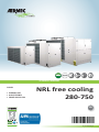
1
60Hz FREE COOLING TECHNICAL MANUAL CHILLER • EXTERNAL UNIT • HIGH EFFICENCY • POWER SUPPLY 60Hz NRL free cooling 280-750 EN 13_01. 5641350_00 EN NRL free cooling 0280-0750 60Hz Dear Customer, Thank you for choosing an AERMEC product. This product is the result of many years of experience and in-depth engineering research, and it is built using top quality materials and advanced technologies. In addition, the CE mark guarantees that our appliances fully comply with the requirements of the European Machinery Directive in terms of safety. We constantly monitor the quality level of our products, and as a result they are synonymous with Safety, Quality, and Reliability. Product data may be subject to modifications deemed necessary for improving the product without the obligation to give prior notice. Thank you again. AERMEC S.p.A AERMEC S.p.A. reserves the right at all times to make any modification for the improvement of its product and is not obliged to add these modification to machines of previous manufacture that have already been delivered or are being built. 13_01. 5641350_00 3 EN NRL free cooling 0280-0750 60Hz INDEX 1. Descrip on and choce of unit ........................................................... 6 2. Check list .......................................................................................... 7 3. Configurator ...................................................................................... 8 4. 4.1. 4.2. Principle of opera on schemes......................................................... 9 Produc on of cold water only the system ........................................ 9 Cold water produc on and the system recovery (desuperheater) . 10 5. 5.1. 5.2. 5.3. 5.4. 5.5. 5.6. Descrip on of the components ...................................................... 11 Chiller circuit ................................................................................... 11 Frame and fans ............................................................................... 11 Hydraulic components (standard version) ...................................... 11 Hydraulic components (configurable version) ................................ 11 Safety and control components ...................................................... 11 Electrical panel control and power ................................................. 12 6. 6.1. 6.2. Accessories...................................................................................... 13 Mechanical accessories................................................................... 13 Electrical accesories ....................................................................... 13 7. Technical data vers. F (chiller func on) ........................................... 14 8. Technical data vers. F (free-cooling mode) ..................................... 17 9. 9.1. Opera ng limits .............................................................................. 18 Design specifica ons ....................................................................... 18 10. 10.1. 10.2. 10.3. Correc on factors ........................................................................... 19 Input power and cooling capacity "high efficiency version" ........... 19 For ∆t different from the rated value .............................................. 19 Fouling factors................................................................................. 19 11. 11.1. 11.2. Free-cooling func oning correc ve factors .................................... 20 For ∆t different from the rated value .............................................. 20 Fouling factors................................................................................. 20 4 12. 12.1. 12.2. Total pressure drops........................................................................ 21 Chiller func on pressure drop ........................................................ 21 Free-cooling func on pressure drop ............................................... 21 13. 13.1. 13.2. 13.3. 13.4. Useful heads ................................................................................... 22 Chiller mode useful heads 230-460/3/60 ....................................... 22 Chiller mode useful heads 575/3/60............................................... 22 Free-cooling mode useful heads 230-460/3/60.............................. 23 Free-cooling mode useful heads 575/3/60 ..................................... 23 14. 14.1. Ethylene glycol solu ons ................................................................. 24 How to interpret glycol curves ........................................................ 24 15. Expansion tank calibra on .............................................................. 25 16. Minimum water content ................................................................. 25 17. Part load .......................................................................................... 26 18. Sound data ...................................................................................... 27 19. 19.1. 19.2. 19.3. 19.4. 19.5. 19.6. Control and safety parameters calibra on...................................... 28 Compressor thermomagne c ......................................................... 29 Pump thermomagne c (03-p3) ...................................................... 29 Pump thermomagne c (04-p4) ...................................................... 29 Fan thermomagne c (220v-3-60hz)................................................ 30 Fan thermomagne c (460v-3-60hz)................................................ 30 Fan thermomagne c (575v-3-60hz)................................................ 30 13_01. 5641350_00 EN NRL free cooling 0280-0750 60Hz 13_01. 5641350_00 5 EN NRL free cooling 0280-0750 60Hz 1. Standards and Directives respected on designing and constructing the unit: PROTECTION RATING 1. IP 24 ACOUSTIC PART: 1. ISO DIS 9614/2 INTENSIMETRIC METHOD 2. SOUND POWER EN ISO 9614 2 3. SOUND PRESSURE (EN ISO 3744) REFRIGERANT GAS: This unit contains fluoride gases with greenhouse effect covered by the Kyoto Protocol. Maintenance and disposal must only be performed by qualified staff. STANDARD: UL 1995 Heating and cooling equipment. ANSI/NFPA Standard 70 National Electrical code (N.E.C.). CSA C.22.1.- C.22.2 Safety Standard Electrical Installation. 6 DESCRIPTION AND CHOCE OF UNIT The NRL Free-cooling series appliances are water chillers equipped with an external air cooling capacity recovery system called "free-cooling". The water free-cooling system consists in integrating and eventually completely replacing the cooling capacity delivered by the compressors through an additional water coil that exploits the low temperature of the external air to cool the system's return water. Maximum reliability The presence of several scroll compressors allows NRL chillers various partialisations of the cooling capacity. OPERATING MODE: FREE-COOLING ONLY: when the external temperature is sufficiently low to allow water cooling inside the free-cooling coils at the desired temperature. This is the most economical mode of the unit with only the fans operating in speed modulation. Models: 1. NRL "F" free-cooling The versions can be in different set-ups at the same time in order to satisfy a wide range of plant engineering solutions: 1. 2. 3. "A" HIGH EFFICIENCY "E" SILENCED HIGH EFFICIENCY "D" WITH DESUPERHEATER The units with desuperheater (D) are not available in the versions: 1. YD 2. XD MIXED FREE-COOLING + COMPRESSORS: the compressors operate in integration with the freecooling when the cooling capacity recovered from the external air is no longer sufficient for the power required by the system. The higher the cooling capacity recovery with free-cooling the lower the integration is. COMPRESSORS ONLY: when the external air temperature is greater than the return temperature of the system water. 13_01. 5641350_00 EN NRL free cooling 0280-0750 60Hz 2. CHECK LIST Ciruit Cooling circuit Resistance carter compressor High pressure switch Low pressure switch High pressure trasducer Low pressure trasducer Solenoid valve of hot gas injecton By-pass valve of hot gas Exchanger (EV- EV/CN) Exchanger (desuperheater) Exchanger (glycol free) Model Components B yes yes no yes yes yes no yes yes yes F yes yes no yes yes yes no yes no no with D yes yes no yes yes yes yes yes yes / Hydraulic circuit Water filter Flow switch Air vent "F" VERSION Version "F 00" 0280 0300 0330 yes yes yes yes yes yes yes yes yes 0350 yes yes yes 0500 yes yes yes 0550 yes yes yes 0600 yes yes yes 0650 yes yes yes 0700 yes yes yes 0750 yes yes yes Hydraulic circuit Water filter Flow switch Safety valve Air vent Pump Expansion tank Version "P1…P4" 0280 yes yes yes yes yes yes 0300 yes yes yes yes yes yes 0330 yes yes yes yes yes yes 0350 yes yes yes yes yes yes 0500 yes yes yes yes yes yes 0550 yes yes yes yes yes yes 0600 yes yes yes yes yes yes 0650 yes yes yes yes yes yes 0700 yes yes yes yes yes yes 0750 yes yes yes yes yes yes Hydraulic circuit Water filter Flow switch Safety valve Air vent Pump Expansion tank Storage tank Version "01…04" 0280 yes yes yes yes yes yes yes 0300 yes yes yes yes yes yes yes 0330 yes yes yes yes yes yes yes 0350 yes yes yes yes yes yes yes 0500 yes yes yes yes yes yes yes 0550 yes yes yes yes yes yes yes 0600 yes yes yes yes yes yes yes 0650 yes yes yes yes yes yes yes 0700 yes yes yes yes yes yes yes 0750 yes yes yes yes yes yes yes hydraulic circuit Version "F with D" Water filter Differential pressure switch Flow switch Exchanger (desuperheater) VERSION WITH "D" DESUPERHEATER 0280 0300 0330 0350 0500 0550 0600 0650 0700 0750 yes yes yes yes yes yes yes yes yes yes no no no no no no no no no no no no no no no no no no no no yes yes yes yes yes yes yes yes yes yes hydraulic circuit Storage tank version with D" 0280 0300 Water filter yes yes Differential pressure switch no no Flow switch yes yes Exchanger (desuperheater) yes yes Safety valve yes yes Air vent yes yes Pump yes yes Expansion tank yes yes Storage tank yes yes 13_01. 5641350_00 0330 yes no yes yes yes yes yes yes yes 0350 yes no yes yes yes yes yes yes yes 0500 yes no yes yes yes yes yes yes yes 0550 yes no yes yes yes yes yes yes yes 0600 yes no yes yes yes yes yes yes yes 0650 yes no yes yes yes yes yes yes yes 0700 yes no yes yes yes yes yes yes yes 0750 yes no yes yes yes yes yes yes yes 7 EN NRL free cooling 0280-0750 60Hz 3. CONFIGURATOR DESCRIPTION 1, 2, 3 NRL 4, 5, 6 Size 028 - 030 - 033 - 035 - 050 - 055 - 060 - 065 - 070 - 075 7 Compressors 0 Standard compressor 8 Thermostatic valve ° Standard mechanical thermosta c valve with produced water up to 39.2°F / +4°C (1) Y Mechanical thermostatic valve with produced water from 39.2°F / +4°C to -42.8°F / -6°C (1) X Electronic thermosta c valve with produced water up to 39.2°F / +4°C (1) 9 Model F Free-cooling 10 Heat recovery ° Without recovery units D Desuperheater (2) 11 Version A High efficiency (not available for sizes 028 ÷ 035) E High efficiency, silenced version (on demand for sizes 050 ÷ 075) (2) 12 ° R S V Coils Made of aluminium Made of copper Tinned copper Painted aluminium (epoxy paint) 13 Ventilation I Fan speed modula ng for condensa on control 14 Power supply 6 230V-3-60Hz with thermomagnetic switches (2) 7 460V-3-60Hz with thermomagnetic switches 8 575V-3-60Hz with thermomagnetic switches 15, 16 00 03 04 P3 P4 (1) (2) 8 Hydronic kit Without hydronic kit Water storage tank and high-head single pump Water storage tank, with high-head pump and reserve pump Without water storage tank, with high-head pump Without water storage tank, with high-head pump and reserve pump For lower temperatures, contact the office. Versions avaible only on demand 13_01. 5641350_00 EN NRL free cooling 0280-0750 60Hz 4. PRINCIPLE OF OPERATION SCHEMES 4.1. PRODUCTION OF COLD WATER ONLY THE SYSTEM Description 1 exchanger SYSTEM SIDE exchanger 2 SOURCE SIDE exchanger 3 SYSTEM SIDE CN 2 Operation (EVAPORATION) Production cold water (CONDENSATION) Heat exchange with the air (EVAPORATION FREE-COOLING) Production cold water CN Sign CP CN TEV BHE V3V 2 CP Description compressor Air side exchange Thermostatic valve Exchanger plate three-way valve CP CN 3 TEV TEV BHE V3V H2O RETURN SYSTEM H2O DISCHARGE SYSTEM 1 13_01. 5641350_00 9 EN NRL free cooling 0280-0750 60Hz 4.2. COLD WATER PRODUCTION AND THE SYSTEM RECOVERY DESUPERHEATER Description exchanger 1 SYSTEM SIDE exchanger 2 SOURCE SIDE exchanger 3 SYSTEM SIDE BHE H2O SUPPLY 4 H2O DISCHARGE CN 4 exchanger DESUPERHEATER 2 Sign CP CN TEV BHE V3V CN 2 CP Operation (EVAPORATION) Production of cold water (CONDENSATION) Heat exchange with the air (EVAPORATION FREE-COOLING) Production cold water (CONDENSATION) hot water (after heating - Swimming pools ...) Description Compressor Air side exchange Thermostatic valve Exchanger plate three-way valve CP CN 3 TEV TEV BHE V3V H2O RETURN SYSTEM H2O SUPPLY SYSTEM 1 10 13_01. 5641350_00 EN NRL free cooling 0280-0750 60Hz 5. DESCRIPTION OF THE COMPONENTS 5.1. CHILLER CIRCUIT SCROLL COMPRESSORS High efficiency scroll-type hermetic compressors, assembled on elastic antivibration supports, driven by a 2-pole electric motor with internal thermal protection. of the electric heater casing included as standard. The heater is automatically powered when the unit stops, provided that the unit is kept under tension. WATER SIDE HEAT EXCHANGER Of the plate-type (AISI 316), externally insulated with closed cell material to reduce thermal dispersion. Fitted, as standard, with antifreeze heater. 5.1.1. WATER FEATURES PH Electric conductivity Chloride ions Sulphuric acid ions Total iron Alkalinity M Total hardness Sulphur ions ammonia ions Silicone ions 6-8 less than 200 mV/cm (77°F / 25°C) less than 50 ppm less than 50 ppm less than 0.3 ppm less than 50 ppm less than 50 ppm none none less than 30 ppm SOURCE SIDE HEAT EXCHANGER Made with copper pipes and aluminium louvered fins blocked by mechanical expansion of the pipes. Provided with protective grid. DESUPERHEATER Unit with (AISI 316) heat plate, insulated externally with closed cell material to reduce heat loss. DEHYDRATOR FILTER Hermetic-mechanical with cartridges made of ceramic and hygroscopic material, able to withhold impurities and any traces of humidity present in the cooling circuit. ONE WAY VALVES Allows the passage of the refrigerant in just one direction. THERMOSTATIC VALVE The valve with external equaliser positioned at the evaporator inlet, modulates the flow of gas to the evaporator, according to the heat load, in order to ensure a correct heating level of the intake gas. SOLENOID VALVE The valve closes when the compressor turns off, preventing the flow of refrigerant gas towards the evaporator. SIGHT GLASS Used to check the refrigerant gas load and the eventual presence of humidity in the cooling circuit. 13_01. 5641350_00 TAPS Present in the liquid and discharge lines, and allow to intercept the refrigerant in case of extraordinary maintenance. 5.2. FRAME AND FANS SUPPORT FRAME Load-bearing structure Made of hot-galvanised steel sheet of a suitable thickness, varnished with polyester powders able to resist atmospheric agents over time. EXPANSION TANK Of the membrane type, with nitrogen pre-charge. SAFETY VALVE Calibrated to 87psi / 6bar and with ductable discharge, it releases overpressure in the event of abnormal working pressure levels. STORAGE TANK In order to reduce the thermal dispersion and eliminate the phenomenon of the formation of condensation, it is insulated with polyurethane material of a suitable thickness. FAN UNIT Axial fan, balanced statically and dynamically. The electric fans are protected electrically by magnet-circuit breakers and mechanically by anti-intrusion metal grids, according to the IEC EN 60335-2-40 Standard. 5.5. 5.3. HIGH PRESSURE TRANSDUCER Placed on high pressure side of cooling circuit, signals the work pressure to control board, generating a pre-warning in case abnormal pressure occurs. HYDRAULIC COMPONENTS standard version AIR WATER HEAT EXCHANGER FREE COOLING Crossed by water for the free-cooling function. Is made of copper pipes and aluminium blades blocked through the mechanical expansion of the pipes. (High efficiency type). 3 WAY VALVE This is an electric servo-controlled ON-OFF diverting valve on the water side of the freecooling circuit controlled. WATER FILTER Allows you to block and eliminate any impurities in the hydraulic circuits. Inside, it has a filtering mesh with holes not greater than one millimetre. It is essential for avoiding serious damage to the plate-type exchanger. FLOW SWITCH Controls that the water is circulating, otherwise the unit blocks. AIR VENT Of the automatic type, assembled on the upper part of the hydraulic system; it releases any air bubbles that may be present in the system. 5.4. HYDRAULIC COMPONENTS (configurable version) DRAIN VALVE Of the automatic type, assembled on the upper part of the hydraulic system; it releases any air bubbles that may be present in the system. CIRCULATION PUMPS HIGH PUMP Depending on the characteristics of the pump chosen, it offers a useful head to overcome the pressure drops in the system. SAFETY AND CONTROL COMPONENTS HIGH PRESSURE SWITCH With fixed calibration, placed on high pressure side of cooling circuit, inhibits functioning of compressor if abnormal work pressure occurs. LOW PRESSURE TRANSDUCER Allows displaying, on the microprocessor board display, the value of the compressor's suction pressure (one per circuit) on the low-pressure side of the cooling circuit EVAPORATOR ANTIFREEZE HEATING ELEMENT Its operation is commanded by the antifreeze probe located in the plate evaporator. It is activated when the water temperature is +3°C, and deactivated when the water temperature is +5°C. The dedicated software in the regulation card manages the heater. SAFETY VALVE Equipped with a piped discharger and intervenes by discharges the over pressure in case of anomalous pressures. - Set at 45 bar on the branch HP - Set at 30 bar on the branch LP DCPX_UL CONDENSATION PRESSURE CONTROLLER This accessory allows correct functioning when external temperatures drop below 50 °F / 10°C (up to 14 °F / -10°C). It consists of an adjustment circuit board that varies the number of fan revs according to the condensation pressure, read by the high pressure transducer, in order to keep it sufficiently high for correct unit functioning. 5.6. ELECTRICAL PANEL CONTROL AND POWER Electric board in compliance with standards EN 60204-1/IEC 204-1, complete with: 11 EN NRL free cooling 0280-0750 60Hz - door lock main isolating switch, fuses and contactors for compressors and fans, terminals for REMOTE PANEL, spring type control circuit terminal board, outdoor electric board with double door and gaskets, - electronic controller, - evaporator pump and recovery pump control consent relay - all numbered cables. DOOR BLOCK DISCONNECTING SWITCH IT is possible to access the electrical panel by disconnecting the voltage, then using the opening lever of the panel itself. This lever can be blocked with one or more padlocks during maintenance, in order to prevent the machine being powered up accidentally. REMOTE CONTROL PANEL PR3 This allows the chiller command operations to be given from a distance. compressor protection thermomagnetic switch; fan protection thermomagnetic switch; auxiliary protection thermomagnetic switch; discharge gas temperature control thermostat CONTROL KEYPAD Provides full control functions. For a detailed description refer to the user manual. Electronic regulation GR3 −Consis ng of a management/control card and a visualisa on card. − Func ons carried out: − adjustment of water temperature at evaporator inlet, with thermostat control for up to 4 levels and integral-propor onal fan speed control (with DCPX_UL); − compressor start-up delay; − compressor sequence rota on; − count of compressor work hours; − start/stop; − reset; − permanent alarms memory; − autostart a er voltage drop; − mul -lingual messages; − opera on with local or remote control. Machine status display: 1. alarms sumary; 2. ON/OFF compressors. Display of the following parameters 1. water inlet temperature; 2. accumulator temperature; 3. water outlet temperature; 4. ∆T; 5. high pressure; 6. low pressure; 7. wai ng me for restart; 8. alarms visualisa on. For further informa on, refer to the user manual. 12 13_01. 5641350_00 EN NRL free cooling 0280-0750 60Hz 6. ACCESSORIES 6.1. MECHANICAL ACCESSORIES VT Group of anti-vibration, to be installed under the base. GP Protection grille, protects the external coil from accidental knocks. 6.2. ELECTRICAL ACCESORIES AERWEB300 Accessory AERWEB allows remote control of a chiller through a common PC and an ethernet connection over a common browser; 4 versions available: - AERWEB300-6: Web server to monitor and remote control max. 6 units in RS485 network; - AERWEB300-18: Web server to monitor and remote control max. 18 units in RS485 network; 13_01. 5641350_00 AERWEB300-6G: Web server to monitor and remote control max. 6 units in RS485 network with integrated GPRS modem; AERWEB300-18G: Web server to monitor and remote control max. 18 units in RS485 network with integrated GPRS modem; DRE It allows the reduction of peak power necessary for the machine during start-up phase. Accessories can only be fitted in the factory. DUALCHILLER Simplified control system to switch on and off, and command, two chillers (using Aermec GR3 command) in a single system, as if they were a single unit. units are installed in parallel, always ensuring a constant delivery to the evaporators. PGS: Daily/Weekly Programmer. Allows you to programme two time bands per day (two switch on/off cycles) and to have differentiated programming for each day of the week. PRM1-PRM2 FACTORY FITTED ACCESSORY. It is a manual pressure switch electrically wired in series with the existing automatic high pressure switch on the compressor discharge pipe. AER485 RS-485 interface for supervision systems with MODBUS protocol. FOR MORE INFORMATION PLEASE CONTACT US MULTICHILLER Control system to switch the individual chillers on and off, and command them, in a system in which several 13 EN NRL free cooling 0280-0750 60Hz 7. TECHNICAL DATA vers. F (CHILLER FUNCTION) Model 0300 0330 0350 0500 0550 0600 0650 0700 0750 13.16 16.38 15.18 19.52 17.44 22.32 21.39 29.95 23.84 33.30 - 27.23 40.02 - 34.06 48.02 - 37.91 56.23 - 41.17 64.65 - 46.24 65.05 - FA FE FA FE Alls Alls Alls Alls FA 230V-460V kW - - - - 35.65 42.37 51.02 59.23 67.65 68.05 Total power input with HIGH - PUMP FE 230V-460V kW 18.73 21.87 24.67 32.30 - - - - - - 575V 575V Alls Alls Alls Alls 17.88 32 6 21.02 36 5 23.82 42 7 31.45 51 8 35.50 57 7 - 42.22 65 9 - 51.02 82 10 - 59.23 91 10 - 67.65 99 12 - 68.05 111 12 - Cooling capacity Total power input Water flow rate Total pressure drop Useful head with HIGH - PUMP FA FE FA FE FA FE Tons Tons kW kW 0280 kW kW gpm gpm psi psi FA 230V-460V psi - - - - 24 21 30 28 26 24 FE FA FE 230V-460V psi 575V psi 575V psi 27 28 28 28 26 25 24 23 23 - 21 - 30 - 28 - 26 - 24 - FA FE FA FE Alls Alls Alls Alls 9.65 11.85 9.34 11.82 9.39 11.89 8.58 11.48 8.60 12.02 - 8.17 11.92 - 8.52 12.56 - 8.10 12.19 - 7.65 11.87 - 8.54 11.51 - 24 24 24 24 24 24 24 24 24 24 54.30 30.80 25.60 62.60 35.00 29.10 71.30 40.50 34.20 93.40 49.50 42.40 103.10 52.00 42.00 - 120.80 60.80 49.60 - 146.90 75.50 61.20 - 170.20 85.10 69.80 - 194.80 95.20 78.90 - 199.10 99.40 81.60 - 235 134 108 82 52 43 113 67 54 110 60 50 283 161 111 90 61 49 127 81 63 125 80 60 294 171 119 101 71 57 138 91 71 125 90 70 375 201 156 146 83 74 203 108 97 200 100 90 376 189 138 148 70 57 205 95 79 200 90 75 - 389 200 146 161 81 64 218 106 86 200 100 80 - 373 199 134 180 99 72 218 119 86 200 110 80 - 454 229 171 225 110 89 283 135 112 250 125 110 - 494 239 186 265 120 105 323 145 127 300 125 125 - 539 272 214 277 130 115 339 159 141 300 150 125 - ENERGY INDICES EER IPLV BTU/Wat BTU/Wat BTU/Wat BTU/Wat PROTECTION RATING IP ELECTRICAL DATA Total input current (1) FA FE FA FE FA FE 230V A 460V A 575V A 230V A 460V A 575V A 230V A 460V A 575V A 230V A 460V A 575V A 230V A 460V A 575V A Model WITHOUT PUMP L.R.A. M.C.A. M.O.P. RECOM FUSE FA FE FA FE FA FE FA FE FA FE FA FE FA FE FA FE FA FE FA FE FA FE FA FE COOLING AHRI STANDARD CONDITIONS Outlet water temperature 6.7°C / 44,6 °F Flow rate 0.043l/s per kW External temperature 35°C / 95 °F (1) 14 data refered to no pump version AHRI conditions: leaving water 6.7°C / 44.6°F flow rate 0.043 l/s per kW (full load) Load 100% air 35°C / 95°F Load 75% air 26.7°C / 80.06°F Load 50% air 18.3°C / 64.94°F Load 25% air 12.8°C / 55.04°F 13_01. 5641350_00 EN NRL free cooling 0280-0750 60Hz Model 0280 0300 0330 0350 0500 0550 0600 0650 0700 0750 243 123 291 167 302 175 383 194 384 194 141 397 210 149 383 220 138 464 239 175 504 245 190 549 288 218 110 90 43 45 121 50 56 110 70 50 113 98 51 51 135 70 65 125 80 60 121 109 59 59 146 75 73 125 90 70 158 154 66 77 211 80 99 200 110 90 156 78 60 213 90 82 200 90 80 - 169 82 67 226 100 89 225 110 80 - 190 104 76 228 125 90 225 110 90 - 235 111 93 293 125 116 250 125 110 - 275 117 109 333 125 131 300 150 125 - 287 126 119 349 150 145 300 150 125 - n°/n° 2/2 2/2 2/2 2/2 3/2 3/2 4/2 4/2 4/2 4/2 gal Ø 0,8 2"½ 1,1 2"½ 1,1 2"½ 1,3 2"½ 1,7 2"½ 1,7 2"½ 2,2 2"½ 2,9 2"½ 2,9 2"½ 3,4 2"½ Model WITH HIGH HEAD PUMP L.R.A. M.C.A. M.O.P. RECOM FUSE SCROLL COMPRESSORS Quantity / circuits HEAT EXCHANGER SYSTEM SIDE Exchanger capacity Hydraulic connenction FA FE FA FE FA FE FA FE FA FE FA FE FA FE FA FE FA FE FA FE FA FE FA FE 230V A 460V A 575V A 230V A 460V A 575V A 230V A 460V A 575V A 230V A 460V A 575V A COOLING AHRI STANDARD CONDITIONS Outlet water temperature 6.7°C / 44,6 °F Flow rate 0.043l/s per kW External temperature 35°C / 95 °F (1) data refered to no pump version 13_01. 5641350_00 AHRI conditions: leaving water 6.7°C / 44.6°F flow rate 0.043 l/s per kW (full load) Load 100% air 35°C / 95°F Load 75% air 26.7°C / 80.06°F Load 50% air 18.3°C / 64.94°F Load 25% air 12.8°C / 55.04°F 15 EN NRL free cooling 0280-0750 60Hz Model 0280 0300 0330 0350 0500 0550 0600 0650 0700 0750 HYDRONIC GROUP SYSTEM SIDE STORAGE TANK Storage tank capacity n°/gal 79 79 79 79 79 79 79 79 79 132 EXPANSION TANK Expansion tank Expansion tank calibration n°/gal psi 6,6 21,8 6,6 21,8 6,6 21,8 6,6 21,8 6,6 21,8 6,6 21,8 6,6 21,8 6,6 21,8 6,6 21,8 6,6 21,8 2,35 7,00 3,34 4,42 2,35 7,00 3,34 4,21 2,35 7,00 3,34 4,26 2,35 7,00 3,34 3,88 2,35 7,00 3,34 3,67 2,35 7,00 3,34 3,57 3,00 10,40 4,94 4,72 3,00 10,40 4,94 4,54 3,00 10,40 4,94 4,42 3,00 10,40 4,94 4,58 87 87 87 87 87 87 87 87 87 87 54.30 30.80 25.60 62.60 35.00 29.10 71.30 40.50 34.20 93.40 49.50 42.40 103.10 52.00 42.00 - 120.80 60.80 49.60 - 146.90 75.50 61.20 - 170.20 85.10 69.80 - 194.80 95.20 78.90 - 199.10 99.40 81.60 - 6 14750 6.96 6.96 6.96 1.56 1.56 1.56 6 14514 6.96 6.96 6.96 1.56 1.56 1.56 8 18172 9.28 9.28 9.28 2.08 2.08 2.08 8 18172 9.28 9.28 9.28 2.08 2.08 2.08 2 23836 13.0 7.6 6.64 4.0 4.0 4.36 2 23836 13.0 7.6 6.64 4.0 4.0 4.36 3 37170 19.5 11.4 9.96 6.0 6.0 6.54 3 36580 19.5 11.4 9.96 6.0 6.0 6.54 3 36580 19.5 11.4 9.96 6.0 6.0 6.54 3 36580 19.5 11.4 9.96 6.0 6.0 6.54 42 74 43 75 45 77 46 78 51 83 51 83 52 84 53 85 54 86 55 87 9,0 21,83 9,0 21,83 12,5 27,56 12,0 26,46 13,5 29,76 13,5 29,76 14,0 30.86 22,3 49.16 9,5 20,94 5,4 11,90 3,0 6,61 13,5 29,76 14,0 30,86 6,0 13,23 3,0 6,61 13,5 29,76 6,0 13,23 6,0 13,23 74 43 126 1110 2449 74 43 126 1119 2467 74 43 156 1369 3020 HIGH HEAD PUMP Pump power input kW 230V 460V 575V Pump input current A SAFETY VALVE Safety valve calibration psi ELECTRICAL DATA Total input current (1) FA FE FA FE FA FE FAN MOTORS Quantity Air flow Fan input current Fan power input - 230V A 460V A 575V A n° CFM 230V 460V 575V 230V 460V 575V SOUND DATA Sound pressure Sound power A A A kW kW kW dB(A) dB(A) CHARGE The data reported can be changed at any time if deemed necessary from Aermec C1 R410A Gas refrigerant C2 C1 Oil C2 DIMENSION Height Width Depth Weight when empty in in in kg lib COOLING AHRI STANDARD CONDITIONS Outlet water temperature 6.7°C / 44,6 °F Flow rate 0.043l/s per kW External temperature 35°C / 95 °F (1) 16 data refered to no pump version kg lib 9,9 21,83 kg lib kg lib kg lib 9,9 21,83 2,7 5,95 2,7 5,95 63 43 116 837 1847 9,0 21,83 3,0 6,61 2,7 5,95 3,0 6,61 3,0 6,61 9,0 21,83 3,0 6,61 3,0 6,61 63 43 116 908 2002 63 43 116 923 2037 63 43 116 937 2066 9,0 21,83 9,0 21,83 9,0 21,83 6,0 13,23 6,0 13,23 23,5 51.81 6,0 13,23 6,4 14,11 74 43 156 1450 3197 74 43 156 1470 3241 77 59 171 1789 3946 6,0 13,23 6,0 13,23 AHRI conditions: leaving water 6.7°C / 44.6°F flow rate 0.043 l/s per kW (full load) Load 100% air 35°C / 95°F Load 75% air 26.7°C / 80.06°F Load 50% air 18.3°C / 64.94°F Load 25% air 12.8°C / 55.04°F 13_01. 5641350_00 EN NRL free cooling 0280-0750 60Hz 8. TECHNICAL DATA vers. F (FREE-COOLING MODE) Model Cooling capacity Total power input Water flow rate Total pressure drop Useful head with HIGH - PUMP FA FE FA FE FA FE FA FE FA FE FA FE 0280 0300 0330 0350 0500 0550 0600 0650 0700 0750 Tons Tons kW kW gpm gpm psi psi psi psi psi psi 10.22 2.06 32 9 24 24 13.21 2.06 36 7 26 26 15.47 2.58 42 9 23 23 16.55 2.58 51 11 21 20 18.48 4.67 57 9 22 21 - 19.39 4.67 65 12 18 18 - 25.19 6.59 82 14 26 26 - 29.82 6.66 91 15 24 24 - 30.68 6.66 99 17 20 20 - 32.71 6.66 111 19 17 17 - BTU/Wat BTU/Wat 59.58 77.04 72.02 77.06 47.55 - 49.89 - 45.91 - 53.79 - 55.34 - 59.00 - - - 24 24 24 24 24 24 24 24 24 24 230V A 460V A 575V A 7.0 7.0 7.0 7.0 7.0 7.0 9.3 9.3 9.3 9.3 9.3 9.3 13.0 7.6 6.6 - 13.0 7.6 6.6 - 19.5 11.4 10.0 - 19.5 11.4 10.0 - 19.5 11.4 10.0 - 19.5 11.4 10.0 - 42 74 43 75 45 77 46 78 51 83 51 83 52 84 53 85 54 86 55 87 Alls Alls Alls Alls Alls Alls Alls Alls 230V-460V 230V-460V 575V 575V ENERGY INDICES EER PROTECTION RATING IP FA Alls FE Alls - ELECTRICAL DATA Total input current (1) SOUND DATA Sound pressure Sound power FREE COOLING MODE AHRI STANDARD CONDITIONS Inlet water temperature Outside air temperature Rated water flow Compressors off 13_01. 5641350_00 FA FE FA FE FA FE dB(A) dB(A) (1) 15°C / 59°F 2°C / 35.6°F data refered to no pump version AHRI conditions: leaving water 6.7°C / 44.6°F flow rate 0.043 l/s per kW (full load) Load 100% air 35°C / 95°F Load 75% air 26.7°C / 80.06°F Load 50% air 18.3°C / 64.94°F Load 25% air 12.8°C / 55.04°F 17 EN NRL free cooling 0280-0750 60Hz °C 50 45 40 35 30 25 20 15 10 5 0 23 14 5 -5 -10 -15 ATTENTION Wind breaks should be implemented if the unit is installed in particularly windy areas, to prevent a malfunction of the unit. 9.1. 46 °C 114,8 °F 36 °C 96,8 °F Functioning with glycoled water Functioning with DCPX accessory + water glycoled 17,6 -8 19,4 -7 21,2 -6 23,0 -5 24,8 -4 26,6 -3 28,4 -2 30,2 -1 32,0 0 33,8 1 35,6 2 37,4 3 External air temperature b.s. The devices in their standard configurations are not suitable for installation in salty environments. For the operating limits, refer to diagram, valid for AHRI standard conditions. Wind breaks should be implemented if the unit is installed in particularly windy areas, to prevent a malfunction of the unit. °F 122 113 104 95 86 77 68 59 50 41 32 Thermosta c valve Y STANDARD functioning Functioning with accessory DCPX 66,2 19 68,0 20 OPERATING LIMITS 39,2 4 41,0 5 42,8 6 44,6 7 46,4 8 48,2 9 50,0 10 51,8 11 53,6 12 55,4 13 57,2 14 59,0 15 60,8 16 62,6 17 64,4 18 9. °C °F Thermosta c valve ° Thermosta c valve X Temperature of the water produced EVAPORATOR DESIGN SPECIFICATIONS REFRIGERANT SIDE High pressure Low pressure side side Acceptable maximum pressure bar/PSI 45/653 30/435 Acceptable maximum temperature Acceptable minimum temperature °C / °F °C / °F 120 / 248 -30 /- 22 51 / 131 -30 / -22 WATER SIDE Acceptable maximum pressure bar/PSI ATTENTION Contact our technical sales department if the unit needs to operated outside the operating limits. 6/87 Hydarulic circuit safety valve (only in version with storage tank or with pump) Calibrated at 6/87 bar/PSI and with piped discharge, which intervents by discharging overpressure if abnormal work pressure occur. Note: 1 - In summer mode the unit can be started with external air 46°C/114,8°F and water inlet 35°C/95°F. In winter mode the unit can be started with external air -15°C/5°F and water inlet 18 20°C/68°F. Operate in such condi ons is permitted only for a short me and to bring the system up to temperature. To reduce the me of this opera on, it is recommended to install a threeway valve that allows bypassing water from the system u li es, un l the condi ons that allow the unit to work within the permi ed opera on limits are achieved. 13_01. 5641350_00 EN NRL free cooling 0280-0750 60Hz 10. CORRECTION FACTORS KEY Cf: correction coefficient of the cooling capacity. 25°C/77°F 1,5 30°C/86°F 1,4 35°C/95°F 1,3 1,2 1,1 40°C/104°F 1 0,9 44°C/111.2°F 0,8 0,7 0,6 0,5 0,4 6.7 -6 -4 -2 0 2 4 6 21.2 24.8 28.4 32.0 35.6 39.2 42.8 Ca: correction coefficient of the input power. 8 10 12 14 16 18 °C 46.4 50.0 53.6 57.2 60.8 64.4 °F 44.6 Processed water temperature CORRECTION COEFFICIENTS OF THE INPUT POWER IN COOLING MODE Correc on coefficients of the input power Ca ATTENZIONE FOR ∆t DIFFERENT FROM 10.01°F / 5.56°C Tab. 10.2 is used for the correction factors of the cooling capacity and input power of the water consumption. To take into account the soiling of the exchanger, apply the relative fouling factors, Tab. 10.3 Outside air temperature The refrigerating capacity yielded and the input electrical capacity in conditions other than rated conditions are obtained by multiplying the rated values (Pf, Pa) by the respective correction coefficients (Cf, Ca). The following diagrams allow you to obtain the correction coefficients to be used for the various versions of the devices, in cold mode; next to each curve you can see the outside air temperature to which it refers. 20°C/68°F 1,6 1,4 1,3 1,2 44°C/111.2°F 40°C/104°F 1,1 35°C/95°F 30°C/86°F 1 25°C/77°F 20°C/68°F 0,9 0,8 Outside air temperature 10.1. INPUT POWER AND COOLING CAPA CITY "HIGH EFFICIENCY VERSION" Correc on coefficients of the cooling capacity Cf CORRECTION COEFFICIENTS OF THE COOLING CAPACITY 0,7 0,6 6.7 -6 -4 -2 0 2 4 6 21.2 24.8 28.4 32.0 35.6 39.2 42.8 8 10 12 14 16 18 °C 46.4 50.0 53.6 57.2 60.8 64.4 °F 44.6 Processed water temperature 10.2. FOR ∆t DIFFERENT FROM THE RATED VALUE ΔT DIFFFERENT FROM THE RATED VALUE ΔT 5°C 10.01°F The performances given by the technical data refer to AHRI standard conditions: flow rate 0.043l/s per kW (∆t 10.01°F / 5.56°C). Use table to obtain the corrective factors of the cooling capacity and input power different than ∆t 10.01°F / 5.56°C. Cooling capacity correction factors Input power correction factors 3°C / 5.40°F 5.56°C / 10.01°F 8°C / 14.40°F 10°C / 18°F 0,99 0,99 1 1 1,02 1,01 1,03 1,02 10.3. FOULING FACTORS The performance levels given by the technical data refer to conditions with clean tubes, with a fouling factor = 1. For other fouling factor values, multiply the data of performance table by the coefficients given. 13_01. 5641350_00 FOULING FACTOR K*M2 / KW Cooling capacity correction factors Input power correction factors 0.018 0.05 0.1 1 0.987 0.967 19 0 °C 5 °C 10 °C EN 15 °C NRL free cooling 0280-0750 60Hz FREE COOLING FUNCTIONING CORRECTIVE FACTORS FREE-COOLING ONLY FUNCTIONING COOLING CAPACITY CORRECTIVE COEFFICIENTS 4,00 -20°C/- 4°F 3,50 -15°C/+5°F 3,00 -10°C/+14°F 2,50 -5°C/+23°F 2,00 0°C/32°F 2°C/35.6°F 5°C/41°F 1,50 10°C/50°F 1,00 15°C/59°F External air temperature The maximum cooling capacity yielded when functioning is completely in free-cooling mode, i.e. all compressors are off, is obtained by multiplying the cooling capacity nominal value (Pf) given in the Technical Data by the respective corrective coefficient, which is obtained from the following diagram on the basis of the temperature of the water produced and the temperature of the external air. These values refer to the fans in full rev conditions (maximum input power). If the power yielded should result in excess, a modulation will intervene on the number of revs. Free-cooling correc ve coefficient (Pf) 11. 0,50 0,00 -10 -8 -6 -4 -2 0 14 17.6 21.2 24.8 28.4 32 2 4 6 8 10 35.6 39.2 42.8 46.4 50 12 14 15 16 18 57.2 59 60.8 64.4 53.6 20 22 24 26 28 °C 68 71.6 82.4 75.2 78.8 °F Temperature of the system return water 11.1. FOR ∆t DIFFERENT FROM THE RATED VALUE ΔT DIFFFERENT FROM THE RATED VALUE ΔT 5°C 10.01°F The performances given by the technical data refer to AHRI standard conditions: flow rate 0.043l/s per kW (∆t 10.01°F / 5.56°C). Use table to obtain the corrective factors of the cooling capacity and input power different than ∆t 10.01°F / 5.56°C. 3°C / 5.40°F 5.56°C / 10.01°F 8°C / 14.40°F 10°C / 18°F Cooling capacity correction factors Input power correction factors 0,99 0,99 1 1 1,02 1,01 1,03 1,02 FOULING FACTOR K*M2 / KW Cooling capacity correction factors Input power correction factors 0.018 0.05 0.1 1 0.987 0.967 11.2. FOULING FACTORS The performance levels given by the technical data refer to conditions with clean tubes, with a fouling factor = 1. For other fouling factor values, multiply the data of performance table by the coefficients given. 20 13_01. 5641350_00 EN NRL free cooling 0280-0750 60Hz 12. TOTAL PRESSURE DROPS 12.1. CHILLER FUNCTION PRESSURE DROP Inlet temperature Outlet temperature Outside air temperature Average water temperature 53.6°F / 12°C 44.6°F / 7°C 95°F / 35°C psi kPa 36 250 29 200 7 6 50°F / 10°C For temperatures other than 50°F / 10°C to use the table of correction factors. 5 PRESSURE DROP 4 22 150 2 3 1 15 7 0 100 1 NRL 280 2 NRL 300 NRL 330 3 NRL 350 4 NRL 500 NRL 550 5 NRL 600 6 NRL 650 NRL 700 7 NRL 750 1 NRL 280 2 NRL 300 NRL 330 3 NRL 350 4 NRL 500 NRL 550 50 0 0 5000 10000 15000 20000 25000 30000 35000 40000 45000 l/h 0 22 44 66 88 110 132 154 176 198 gpm WATER FLOW RATE Average water temperature °F/°C Coefficients 41/5 1,02 50/10 59/15 68/20 86/30 104/40 122/50 1 0,98 0,97 0,95 0,93 0,91 12.2. FREE COOLING FUNCTION PRESSURE DROP 15°C / 59°F 2°C / 35.6°F psi kPa 58 400 51 350 44 300 36 250 7 PRESSURE DROP Inlet water temperature Outside air temperature Rated water flow Compressors off 6 5 3 1 4 2 29 200 22 150 5 NRL 600 15 100 6 NRL 650 NRL 700 7 50 7 NRL 750 0 0 0 5000 10000 15000 20000 25000 30000 35000 40000 45000 0 22 44 66 88 110 132 154 176 198 l/h gpm WATER FLOW RATE Average water temperature °F/°C Coefficients 13_01. 5641350_00 41/5 1,02 50/10 59/15 68/20 86/30 104/40 122/50 1 0,98 0,97 0,95 0,93 0,91 21 EN NRL free cooling 0280-0750 60Hz 13. USEFUL HEADS 13.1. CHILLER MODE USEFUL HEADS 230 460/3/60 psi kPa 44 300 36 250 USEFUL HEADS 29 22 15 200 150 2 NRL 300 NRL 330 3 NRL 350 4 NRL 500 NRL 550 5 NRL 600 6 NRL 650 NRL 700 7 NRL 750 2 50 5 3 0 NRL 280 100 1 7 1 4 0 6 7 0 5000 10000 15000 20000 25000 30000 35000 40000 l/h 0 22 44 66 88 110 132 154 176 gpm WATER FLOW RATE 13.2. CHILLER MODE USEFUL HEADS 575/3/60 psi kPa 44 300 36 250 USEFUL HEADS 29 200 22 150 15 100 1 7 NRL 280 2 NRL 300 NRL 330 3 NRL 350 4 NRL 500 NRL 550 5 NRL 600 6 NRL 650 NRL 700 7 NRL 750 50 2 0 1 5 3 0 4 6 7 0 5000 10000 15000 20000 25000 30000 35000 40000 l/h 0 22 44 66 88 110 132 154 176 gpm WATER FLOW RATE 22 13_01. 5641350_00 EN NRL free cooling 0280-0750 60Hz 13.3. FREE COOLING MODE USEFUL HEADS 230 460/3/60 psi kPa 44 300 6 7 5 36 USEFUL HEADS 29 22 15 7 250 200 150 1 NRL 280 2 NRL 300 NRL 330 3 NRL 350 4 NRL 500 NRL 550 5 NRL 600 6 NRL 650 NRL 700 7 NRL 750 100 50 1 0 2 0 3 4 0 5000 10000 15000 20000 25000 30000 35000 40000 l/h 0 22 44 66 88 110 132 154 176 gpm WATER FLOW RATE 13.4. FREE COOLING MODE USEFUL HEADS 575/3/60 psi kPa 44 300 5 36 6 7 250 3 USEFUL HEADS 29 200 22 150 15 100 7 50 0 0 1 2 1 NRL 280 2 NRL 300 NRL 330 3 NRL 350 4 NRL 500 NRL 550 5 NRL 600 6 NRL 650 NRL 700 7 NRL 750 4 0 5000 10000 15000 20000 25000 30000 35000 40000 l/h 0 22 44 66 88 110 132 154 176 gpm WATER FLOW RATE 13_01. 5641350_00 23 EN NRL free cooling 0280-0750 60Hz • • The correc on factors of cooling power and input power take into account the presence of glycol and diverse evapora on temperatures. The pressure drop correc on factor considers the different flow rate resul ng from the applicaon of the water flow rate correc on factor. The water flow rate correc on factor is calculated to keep the same Δt that would be present with the absence of glycol. 2. 3. ΔP (3) ΔP (4) 1.80 1.70 1.60 ΔP (5) 1.50 1.390 1.40 1.30 1.310 1.20 1.180 1.10 1.00 1.090 0.99 Qw (1) 1.280 1.110 Qw (2) 1.000 Ph 0.990 0.98 Pe 0.975 0.97 0.96 0.95 Pc 0.94 41 32 23 14 Outside air temperature 14.1. HOW TO INTERPRET GLYCOL CURVES If you wish to calculate the percentage of glycol on the basis of the external air temperature, enter from the le axis and on reaching the curve draw a ver cal line, which in turn will intercept all the other curves; the points obtained from the upper curves represent the coefficients for the correc on of the cooling capacity and input power, the flow rates and the pressure drops (remember that these coefficients must be mul plied by the nominal value of the size in ques on); while the glycol percentage value recommended to produce desired water temperature is on the lower axis. If you wish to calculate the percentage of glycol on the basis of the temperature of the water produced, enter from the right axis and on reaching the curve draw a ver cal line, which in turn will intercept all the other curves; the points obtained from the upper curves represent the coefficients for the correc on of the cooling capacity and input power, the flow rates and the pressure drops (remember that these coefficients must be mul plied by the nominal value of the size in ques on); while the lower axis recommends the glycol percentage value necessary to produce water at the desired temperature. ΔP (2) 1.90 KEY: Pc Pe Ph P (1) P (2) P (3) P (4) P (5) Qw (1) Qw (2) 5 0 5 -5 -10 -6 (°C) -4 -15 -20 -13 -25 -22 -30 -31 -35 5 1. ΔP (1) 2.10 2.00 NOTE On the following page an example is given to help graph reading. Using the diagram below it is possible to determine the percentage of glycol required; this percentage can be calculated by taking of the following factors into consideration one: Depending on which fluid is considered (water or air), the graph is interpreted by the right or left side at the crossing point on the curves with the external temperature line or the water produced line. A point from which the vertical line will pass is obtained and this will distinguish both glycol percentage and relative correction coefficients. The curves shown in the diagram summarise a significant number of data, each of which is represented by a specific curve. In order to use these curves correctly it is first necessary to make some initial reflections. 2.20 -40 -40 (°F) (°C) 0 0 5 10 15 20 25 30 35 40 45 % Glycol 50 55 41.0 -3 32.0 21.2 (°F) Processed water temperature • ETHYLENE GLYCOL SOLUTIONS Correction factors 14. Corrective factors for cooling capacity Corrective factors of the input power Corrective factors of heating capacity Correction factors for pressure drop av. temp. = -3.5°C/25.7°F Correction factors for pressure drop av. temp. = 0.5°C/32.9°F Correction factors for pressure drop av. temp. = 5.5°C/41.9°F Correction factors for pressure drop av. temp. = 9.5°C/49.1°F Correction factors for pressure drop av. temp. = 47.5°C/117.5°F Correction factor of flow rates (evap.) av. temp = 9.5°C/49.1°F Correction factor of flow rates (cond.) av. temp = 47.5°C/117.5°F NOTE Although the graph arrives at external air temperatures of -40°C/°F, unit operational limits must be considered. Initial rates for “EXTERNAL AIR TEMPERATURE” and “TEMPERATURE OF PRODUCED WATER”, are not directly related, therefore it is not possible to refer to the curve of one of these rates to obtain corresponding point on the curve of the other rate. 24 13_01. 5641350_00 EN NRL free cooling 0280-0750 60Hz 15. EXPANSION TANK CALIBRATION The standard pressure value for pre-charging the expansion tank is 1.5 bar, and the volume is 25 litres/ 6.6 gallon. Maximum value 6 bar. The tank must be calibrated according to the maximum difference in height (H) of the device (see figure) according to the formula: p (calibration) [bar] = H [m] / 10.2 + 0.3. For example, if the level difference H is 20m, the calibration value of the tank will be 2.3 bar. If the calibration value obtained from the calculation is lower than 1.5 bar (i.e. for H < 12.25), maintain the standard calibration. Ptar = H / 10.2 + 0.3 H max (1) = 180.45ft / 55m H = 40.19ft / 12.25m Ptar = 1.5 bar H Ptar = 1.5 bar H=0m H min (2) KEY (1) Check that the highest user does not exceed a level difference of 180.45ft / 55m. (2) Check that the lowest user can sustain the global pressure acting at that point. 16. MINIMUM WATER CONTENT NRL 0280 0300 0330 0350 0500 0550 0600 0650 0700 0750 13_01. 5641350_00 n° Compressor 2 3 (1) l/KW 7 5 (2) l/KW Key: (1) Minimum water content (2) Minimum water content in the case of process applications or applications with low outside temperatures and low load. 14 10 Regolation on the temperature outlet water. project Δt less than 5°C. 4 4 8 25 EN NRL free cooling 0280-0750 60Hz 17. PART LOAD COOLING (AHRI CONDITIONS) Outlet water temperature Flow rate External temperature 6,7°C / 44,6°F 0,043l/s per kW 35°C / 95°F COOLING CAPACITY % 1% LEVELS OF POWER 2% 3% 4% 0280 55 100 - - 0300 55 100 - - 0330 55 100 - - 0350 55 100 - - 0500 40 75 100 - 0550 36 68 100 - 0600 25 50 75 100 0650 28 50 78 100 0700 25 50 75 100 0750 27 53 77 100 POWER INPUT % 1% 2% 3% 4% 0280 45 100 - - 0300 45 100 - - 0330 45 100 - - 0350 45 100 - - 0500 30 65 100 - 0550 26 58 100 - 0600 20 45 70 100 0650 23 45 73 100 0700 20 45 70 100 0750 23 47 73 100 26 13_01. 5641350_00 EN NRL free cooling 0280-0750 60Hz SOUND DATA Sound power Aermec determines the sound power value on the basis of measurements taken in accordance with standard 9614-2. Sound pressure Sound pressure in free field, on a reflecting plane (directional factor Q=2), in accordance with standard ISO 3744. 13_01. 5641350_00 NRL VERS. 18. Total sound levels Pressure [dB (A)] [dB (A)] 10 m 1m Pot. [dB (A)] 125 250 500 Octave band[Hz] 1000 2000 4000 8000 Sound power by central band frequency [dB (A)] 280 FE 74 42 54 72,2 61,1 66,4 63,5 61,0 50,0 43,7 300 FE 75 43 55 73,2 62,1 67,4 64,5 62,0 51,0 44,7 330 FE 77 45 57 75,1 64,0 69,1 66,3 64,1 53,3 46,8 350 FE 78 46 58 76,1 65,0 70,1 67,6 64,6 55,0 47,1 500 FA 83 51 63 69,1 70,8 75,0 77,7 77,5 75,1 64,8 550 FA 83 51 63 69,1 70,9 76,0 78,5 77,5 73,0 62,0 600 FA 84 52 64 70,4 71,6 76,1 78,9 79,0 75,6 65,1 650 FA 85 53 65 71,4 73,6 77,8 81,1 79,3 75,7 62,2 700 FA 86 54 66 72,9 74,9 78,3 80,6 81,7 75,5 62,4 750 FA 87 55 67 73,9 75,9 79,3 81,6 82,7 76,5 63,4 500 FE 77 45 57 63,0 66,9 70,3 70,7 70,4 67,3 62,9 550 FE 77 45 57 63,0 66,9 70,3 70,7 70,4 67,3 62,9 600 FE 77 45 57 63,3 67,1 70,4 70,8 70,5 67,3 63,1 650 FE 78 46 58 66,7 68,6 69,6 70,8 72,4 66,7 63,0 700 FE 81 49 61 70,9 73,4 73,8 71,0 76,2 70,0 66,9 750 FE 82 50 62 72,3 74,5 74,9 72,1 77,3 71,1 67,8 27 EN NRL free cooling 0280-0750 60Hz 19. CONTROL AND SAFETY PARAMETERS CALIBRATION Min Max. Default Water inlet temperature in cooling mode -10°C / 14°F 20°C / 68°F 7°C / 44,6°F ANTI FREEZE INTERVENTION Intervention temperature of the anti-freeze alarm on the EV side (water outlet temperature) Min -15°C / 5°F Max. 4°C / 39,2°F Default 3°C / 37,4°F Min 3°C / 5,4 Max. 10°C / 18 Default 5°C / 10 COOLING SET TOTAL DIFFERENTIAL Proportional temperature band within which the compressors are activated and deactivated NRL 0280 NRL 0300 NRL 0330 NRL 0350 NRL 0500 NRL 0550 NRL 0600 NRL 0650 NRL 0700 NRL 0750 HIGH PRESSURE PRESSURE SWITCH MANUAL REARM 580 / 40 PA psi / bar 580 / 40 580 / 40 580 / 40 580 / 40 580 / 40 580 / 40 580 / 40 580 / 40 580 / 40 HIGH PRESSURE TRANSDUCER TAP psi / bar 566 / 39 566 / 39 566 / 39 566 / 39 566 / 39 566 / 39 566 / 39 566 / 39 566 / 39 566 / 39 LOW PRESSURE TRANSDUCER TBP psi / bar 29 / 2 29 / 2 29 / 2 29 / 2 29 / 2 29 / 2 29 / 2 29 / 2 29 / 2 29 / 2 COOLING CIRCUIT SAFETY VALVES AP psi / bar 653 / 45 653 / 45 653 / 45 653 / 45 653 / 45 653 / 45 653 / 45 653 / 45 653 / 45 653 / 45 28 13_01. 5641350_00 EN NRL free cooling 0280-0750 60Hz 19.1. COMPRESSOR THERMOMAGNETIC COMPRESSOR THERMOMAGNETIC MTC1 MTC1A MTC2 MTC2A MTC1 MTC1A MTC2 MTC2A MTC1 MTC1A MTC2 MTC2A A A A A A A A A A A A A POWER SUPPLY CIRCUIT NRL 280 NRL 300 NRL 330 NRL 350 NRL 500 NRL 550 NRL 600 NRL 650 NRL 700 NRL 750 35.0 35.0 16.0 16.0 14.5 14.5 - 48.0 35.0 23.0 16.0 19.0 14.5 - 48.0 48.0 23.0 23.0 19.0 19.0 - 54.5 54.5 26.0 26.0 23.0 23.0 - 35.0 35.0 54.5 16.0 16.0 26.0 14.5 14.5 23.0 - 48.0 48.0 54.5 23.0 23.0 26.0 19.0 19.0 23.0 - 48.0 48.0 48.0 48.0 23.0 23.0 23.0 23.0 19.0 19.0 19.0 19.0 48.0 54.5 48.0 54.5 23.0 26.0 23.0 26.0 19.0 23.0 19.0 23.0 54.5 54.5 54.5 54.5 26.0 26.0 26.0 26.0 23.0 23.0 23.0 23.0 59.0 54.5 59.0 54.5 30.4 26.0 30.4 26.0 27.5 23.0 27.5 23.0 POWER SUPPLY NRL 280 NRL 300 NRL 330 NRL 350 NRL 500 NRL 550 NRL 600 NRL 650 NRL 700 NRL 750 220V-3-60Hz 460V-3-60Hz 575V-3-60Hz 220V-3-60Hz 460V-3-60Hz 575V-3-60Hz 7.8 3.9 2.5 7.8 3.9 2.5 7.8 3.9 2.5 7.8 3.9 2.5 7.8 3.9 2.5 7.8 3.9 2.5 7.8 3.9 2.5 7.8 3.9 2.5 10.4 5.2 3.5 10.4 5.2 3.5 10.4 5.2 3.5 10.4 5.2 3.5 11.5 5.8 4.6 11.5 5.8 4.6 11.5 5.8 4.6 11.5 5.8 4.6 11.5 5.8 4.6 11.5 5.8 4.6 14.5 7.2 5.8 14.5 7.2 5.8 POWER SUPPLY NRL 280 NRL 300 NRL 330 NRL 350 NRL 500 NRL 550 NRL 600 NRL 650 NRL 700 NRL 750 220V-3-60Hz 460V-3-60Hz 575V-3-60Hz 220V-3-60Hz 460V-3-60Hz 575V-3-60Hz 220V-3-60Hz 460V-3-60Hz 575V-3-60Hz 220V-3-60Hz 460V-3-60Hz 575V-3-60Hz 7.8 3.9 2.5 7.8 3.9 2.5 7.8 3.9 2.5 7.8 3.9 2.5 7.8 3.9 2.5 7.8 3.9 2.5 7.8 3.9 2.5 7.8 3.9 2.5 7.8 3.9 2.5 7.8 3.9 2.5 7.8 3.9 2.5 7.8 3.9 2.5 7.8 3.9 2.5 7.8 3.9 2.5 7.8 3.9 2.5 7.8 3.9 2.5 10.4 5.2 3.5 10.4 5.2 3.5 10.4 5.2 3.5 10.4 5.2 3.5 10.4 5.2 3.5 10.4 5.2 3.5 10.4 5.2 3.5 10.4 5.2 3.5 11.5 5.8 4.6 11.5 5.8 4.6 11.5 5.8 4.6 11.5 5.8 4.6 11.5 5.8 4.6 11.5 5.8 4.6 11.5 5.8 4.6 11.5 5.8 4.6 11.5 5.8 4.6 11.5 5.8 4.6 11.5 5.8 4.6 11.5 5.8 4.6 14.5 7.2 5.8 14.5 7.2 5.8 14.5 7.2 5.8 14.5 7.2 5.8 220V-3-60Hz 220V-3-60Hz 220V-3-60Hz 220V-3-60Hz 460V-3-60Hz 460V-3-60Hz 460V-3-60Hz 460V-3-60Hz 575V-3-60Hz 575V-3-60Hz 575V-3-60Hz 575V-3-60Hz 1 2 1 2 1 2 19.2. PUMP THERMOMAGNETIC 03 P3 COMPRESSOR THERMOMAGNETIC MP1 MP2 A A A A A A 19.3. PUMP THERMOMAGNETIC 04 P4 COMPRESSOR THERMOMAGNETIC MP1 MP1A MP2 MP2A A A A A A A A A A A A A 13_01. 5641350_00 29 EN NRL free cooling 0280-0750 60Hz 19.4. FAN THERMOMAGNETIC 220V 3 60Hz COMPRESSOR THERMOMAGNETIC MTV1 MTV1A MTV1B MTV1C MTV1D MTV2 MTV2A MTV2B MTV2C MTV2D A A A A A A A A A A CIRCUIT 1 2 NRL 280 NRL 300 NRL 330 NRL 350 NRL 500 NRL 550 NRL 600 NRL 650 NRL 700 NRL 750 8 8 8 8 8 8 - 8 8 8 8 8 8 - 10 10 10 10 10 10 10 10 - 10 10 10 10 10 10 10 10 - 7.2 7.2 - 7.2 7.2 - 7.2 7.2 7.2 - 7.2 7.2 7.2 - 7.2 7.2 7.2 - 7.2 7.2 7.2 - NRL 280 NRL 300 NRL 330 NRL 350 NRL 500 NRL 550 NRL 600 NRL 650 NRL 700 NRL 750 8 8 8 8 8 8 - 8 8 8 8 8 8 - 10 10 10 10 10 10 10 10 - 10 10 10 10 10 10 10 10 - 4.2 4.2 - 4.2 4.2 - 4.2 4.2 4.2 - 4.2 4.2 4.2 - 4.2 4.2 4.2 - 4.2 4.2 4.2 - NRL 280 NRL 300 NRL 330 NRL 350 NRL 500 NRL 550 NRL 600 NRL 650 NRL 700 NRL 750 8 8 8 8 8 8 - 8 8 8 8 8 8 - 10 10 10 10 10 10 10 10 - 10 10 10 10 10 10 10 10 - 3.7 3.7 - 3.7 3.7 - 3.7 3.7 3.7 - 3.7 3.7 3.7 - 3.7 3.7 3.7 - 3.7 3.7 3.7 - 19.5. FAN THERMOMAGNETIC 460V 3 60Hz COMPRESSOR THERMOMAGNETIC MTV1 MTV1A MTV1B MTV1C MTV1D MTV2 MTV2A MTV2B MTV2C MTV2D A A A A A A A A A A CIRCUIT 1 2 19.6. FAN THERMOMAGNETIC 575V 3 60Hz COMPRESSOR THERMOMAGNETIC MTV1 MTV1A MTV1B MTV1C MTV1D MTV2 MTV2A MTV2B MTV2C MTV2D 30 A A A A A A A A A A CIRCUIT 1 2 13_01. 5641350_00 EN NRL free cooling 0280-0750 60Hz 13_01. 5641350_00 31 AERMEC S.p.A. 37040 Bevilacqua (VR) Italy–Via Roma, 996 Tel. (+39) 0442 633111 Telefax 0442 93730–(+39) 0442 93566 www.aermec.com - [email protected] The technical data on the following documents are not binding. Aermec reserves the right to make any changes at any time deemed necessary for product improvement.