1
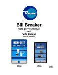
Model 400
Field Service Manual
and
Parts Catalog
For all models
Model
400RL
Rear Load
Model
400FL
Front Load
22190007
January, 2012
RevC
Rowe
400 Field Service Manual & Parts Catalog
Intentionally Left Blank
22190007
Page 2 of 33
Rowe
400 Field Service Manual & Parts Catalog
Table of Contents
Rowe Technical Support and Contact Information................... ..................... .....................
3
Warranty ........ .......................................... ..................... ..................... .....................
6
Mounting Specifications (Dimensions, Weights, Electrical) ....... ..................... .....................
7
Power Cord, Toggle Switches, ON/OFF, and Fuse Locations...... ..................... .....................
8
Changer Installation to meet ADA Requirements .................... ..................... .....................
9
Installing a Rear Load .................................. ..................... ..................... .....................
10
Installing a Front Load ................................. ..................... ..................... .....................
11
Set Up/General Operation............................. ..................... ..................... .....................
12
Switch Descriptions ..................................... ..................... ..................... .....................
13
Programming... .......................................... ..................... ..................... .....................
14
Fast Reconciliation (Fast Recon) .................... ..................... ..................... .....................
15
Reconciliation (Recon).................................. ..................... ..................... .....................
15
Program Reset . .......................................... ..................... ..................... .....................
17
Out of Coin” Message Coin Load / Reconciliation .................... ..................... .....................
18
Configuration Print ...................................... ..................... ..................... .....................
19
Help Code Chart.......................................... ..................... ..................... .....................
20
Status Report .. .......................................... ..................... ..................... .....................
21
Voltage Test Points ...................................... ..................... ..................... .....................
22
Mars Bill Acceptor........................................ ..................... ..................... .....................
New Bill Design Updates
DIP Switch Settings
Cleaning
For More Information
MEI VN2700R – Bill Recycler ......................... ..................... ..................... .....................
Loading Bills
Unloading Bills
New Bill Updates
DIP Switch Settings
Cleaning
For More Information
Coin Hoppers ... .......................................... ..................... ..................... .....................
United States dimes (10¢) and dime sized tokens
Optional Hopper Extensions
Cleaning
For More Information
23
22190007
24
27
Page 4 of 33
Rowe
400 Field Service Manual & Parts Catalog
Parts Catalog ......................................... ..................... ..................... .....................
400RL .. .....................Rear Load, 1-MEI VNR Recycler, 1 MEI 2611 Bill Accepter,
2 coin hoppers......................... ..................... ..................... .....................
400FL .. .....................Front Load, 1-MEI VNR Recycler, 1 MEI 2611 Bill Accepter,
2 coin hoppers, ........................ ..................... ..................... .....................
Printer ............ .......................................... ..................... ..................... .....................
22190007
29
30
31
33
Page 5 of 33
Rowe
400 Field Service Manual & Parts Catalog
Warranty
Rowe extends the original operator of this equipment the following warranty:
All parts are guaranteed to be free of defects in material and workmanship for the specific periods
that follow. Rowe agrees to repair, without charge during such period, any part that proves
defective upon examination by Rowe. All costs of shipping an allegedly defective part to Rowe’s
offices shall be borne by the original operator. Rowe will pay the shipping costs for the replacement
of defective parts.
MEI Bill Acceptor
Changer Electrical Circuit Boards
Changer Electrical and Mechanical Parts
2 years from date of purchase
1 year from date of purchase
1 year from date of purchase
In the case of parts supplied to Rowe as components, Rowe extends the same warranty period as
extended by the original manufacturer.
The above warranty applies provided that all parts of the product have been serviced properly as
directed in the service manual, and provided the alleged defective part, upon examination by
Rowe, shall prove to be thus defective. Under no circumstances shall Rowe be liable for any
incidental, consequential, or special damages, losses or expenses arising from or in connection with
the use of, or the inability to use, the product for any purpose. Rowe reserves the right to make
any changes or improvements in products theretofore manufactured or sold.
This warranty will not apply to any part that has been subjected to accident, abuse, or misuse.
ROWE EXTENDS NO WARRANTY, EXPRESSED OR IMPLIED, TO PURCHASERS OR USERS OF
ITS PRODUCTS EXCEPT AS HEREIN SET FORTH, WHETHER BY OPERATION OF LAW OR
OTHERWISE.
22190007
Page 6 of 33
Rowe
400 Field Service Manual & Parts Catalog
Mounting Specifications
Model:
Type:
Cabinet Dimensions
- Width:
- Depth:
- Height:
Face Plate (DxWxH):
Approx. Shipping Weight:
Power*
- Line Voltage:
- Idle:
- Active:
400
(Front Load)
400 RL
(Rear Load)
Front Load
Rear Load
12.06 in.
18.00 in.
38.62 in.
12.06 in.
18.00 in.
38.62 in.
n/a
.125”D x 18”W x 44.62”H
115 lbs.
130 lbs.
115 VAC, 95-125 VAC
115 VAC, 95-125 VAC
110/115 AC; 60Hz, 130w/1.5A
110/115 AC; 60Hz, 130w/1.5A
110/115 VAC; 60Hz,
230w / 3.5A
110/115 VAC; 60Hz,
230w / 3.5A
*No more than three (3) Bill Breaker units may be connected to a single 15 amp circuit.
Rowe reserves the right to make improvements and changes at any time.
22190007
Page 7 of 33
Rowe
400 Field Service Manual & Parts Catalog
On/Off Switch, Toggle Switches, and Fuses
Fuse
61 NM 250V
5A Slow blow
On/Off
Resume
Status
Recon
Printer outlet
Power Cord
Figure 1
Figure 2
Power Cord
See Figure 1 for Power Cord location.
On/Off Switch, Toggle Switches and Fuses
On/Off, Resume, Status, Recon Switches are shown in Figure 2.
Fuse Locations
There are two fuses used.
1) Fuse, 61 NM, 250V 5A slow blow: Located in the power module above the on/off switch of
the toggle switch box (shown above in Figure 1).
2) Fuse F3.15AH, 250v slow blow: Located on the power supply assembly (see figure below).
IMPORTANT NOTE
Plugging any device (such as drill, vacuum, etc.)
into the printer power receptacle may cause a
blown fuse.
Fuse F3.15AH,250 V
Slow Blow
Power Supply Assembly
22190007
Page 8 of 33
Rowe
400 Field Service Manual & Parts Catalog
Changer Installation to Meet ADA Requirements
The American Disabilities Act requires unobstructed access to equipment. It is to be no
lower than 15 inches and no higher than 54 inches from the ground. This requirement
must be met whether a changer is installed on a base, on a table, or in the wall.
Wall
Bill Acceptor
Model 400
Bill Changer
Max 54”
Max 28 inches
FLOOR
22190007
Page 9 of 33
Rowe
400 Field Service Manual & Parts Catalog
Installing a Rear Load Model 400
General
For all methods of installation, locate a convenient power source and be sure that the bill
changer is mounted level.
The Rear Load Changer is primarily designed to be flush mounted on a wall with the
cabinet itself protruding through a hole (or cutout) in the wall. The cutout should be
determined by the cabinet dimensions shown on page 7. The faceplate, attached to the
cabinet, is mounted tight (or flush) against the outside surface of the wall and secured
with two angle braces (one on each side of the bill changer). See below for an illustration
of this mounting technique. The wall should be flat and vertical so that when the changer
is mounted to the wall, no gap exists between the wall and the stainless steel panel. If the
changer is mounted on an outside wall, apply a liberal bead of sealant or caulking to the
backside of the panel near the four outside edges to ensure a good weather seal and
discourage prying.
Typical Wall Mounting
1. Refer to page 6 for cabinet dimensions and then make an opening in the wall just
large enough for the changer cabinet. (Determine the bill changer mounting height
before you start cutting into the wall.)
2. Depending on the wall thickness, locate and drill three ¼-inch diameter (or larger)
holes in each side of the cabinet as shown below. Drill the holes in the angle-iron
to match the holes in the cabinet.
3. Set the bill changer in the opening in the wall and apply a bead of sealant or
caulking to the back side of the faceplate. Position the faceplate tight against the
wall and fasten the angle braces to the sides of the bill changer with ¼-inch
diameter screws or screws that match the holes drilled in Step#2. Make sure that
the faceplate is tight against the wall.
22190007
Page 10 of 33
Rowe
400 Field Service Manual & Parts Catalog
Installing a Front Load Model 400
IMPORTANT NOTE:
Do not position the rear side of the mounting base flush with a
wall. The rear side of the cabinet must hang over the rear side
of the base by 1/2 inch to allow for the power cord to exit from
the underside rear corner of the cabinet.
1. Position the changer on the base, then mark the mounting hole locations on the floor
and/or wall.
2. Mount the base to the floor leaving at least ½ inch clearance between the rear base
panel and the wall.
NOTE: A spacer may be needed between the rear base panel
and the wall.
3. Place the Model 400 Changer on top of the base.
4. Square up the cabinet to the base and install the two (2) 1/4x20 screws with ½”x1 ¼”
spacers in the two (2) front holes as shown in Figure 1. Use the screws, spacers and
Allen wrench provided.
5. Remove the coin hoppers from the cabinet.
6. Install the other four (4) 1/4x20 screws and spacers along the left and right side of the
cabinet.
7. For extra security, additional screws can be inserted through the rear cabinet panel
into the wall.
Use Allen Wrench
and hardware
provided
Figure 1
22190007
Page 11 of 33
Rowe
400 Field Service Manual & Parts Catalog
Set Up/General Operation
When you first receive your new Changer, it may need to be configured for your use.
Some options may be factory set but they are generic and may need to be reset. Refer
to Program Reset on page 16.
There are three toggle switches on the side of the main board, located in the upper right
side of the cabinet. (See below)
22190007
Page 12 of 33
Rowe
400 Field Service Manual & Parts Catalog
Switch Descriptions:
Resume:
Brings you to the next part of the program.
Pressing the resume switch confirms and enters the data
Status:
Moves the cursor on the display during the set up procedure.
Pressing the status switch moves the cursor through the data fields
from left to right.
Displays reconciliation data without clearing data.
Recon:
Toggles between all yes/no questions, as well as all numeric questions.
Pressing the recon switch changes the data in the data field.
Displays reconciliation data and allow clearing of data.
Also located in this area are the connections for the internal printer, if used, a power
outlet, and the printer port connection. The main power switch (see photo) is also located
in this area. The main board can be accessed by removing the screw that secures the
control panel.
This is a good time to check any connections that may have come loose during shipping,
check that the coin hoppers are secure in mounting plate and tight against coin cup.
Remove all packing materials which maybe around the components. Check that the Mars
bill validator, harnesses, and bill box are secure.
The Changer can be mounted to a base style cabinet or installed into a wall if you have a
Rear Load model. Securely bolt down the Bill Breaker whether on a base or in a wall. The
power required is 110 volts with a 15-amp surge.
22190007
Page 13 of 33
Rowe
400 Field Service Manual & Parts Catalog
Programming – 400 Front Load and Rear Load
Switches
Results
Resume
Brings you to the next line of the program.
Status
Moves the cursor on the Display during the setup procedures.
During operation displays reconciliation data and rests all totals to zero
balances.
Recon
Toggles between all yes and no questions and is used for all number
entries (1, 2, 3, 4, …).
Display
Function
Enter Mach #
000000
Printer Installed
Y
Coin Dispenser #1 Y/N?
y
Enter Load in # Pieces
1000
#1000 Load OK?
Y/N
Enter piece value X.XX
000
$0.25 Pieces Y/N
Y
Coin Dispenser #2 Y/N?
Y
Enter Load in # Pieces
1000
#1000 Load OK?
Y/N
Enter piece value X.XX
000
$0.25 Pieces Y/N
Y
Enable $ 1 Entry
N
# From Recycler
00
$1
# of $0.25 Coins H1
00
$1
Configuration OK Y/N
Establishes machine ID# choce # using Recon
and Status switches, then Resume
Answer Y or N using the Recon switch, then
Resume
Checks to see if coin dispenser #1 is installed.
Answer Y or N using Recon, then Resume
Enter total # of coins using Status & Recon,
then Resume
Verifies # of coins, answer Y/N using Recon,
then Resume
Using Status & Recon enter 25 then Resume
Printing Report
Printed report OK?
Ready to Accept Bill
22190007
(Press Resume switch after completing each function).
Verifies the value of the coins. Using Recon
answer Y/N, then Resume
Anser Y or N using Recon, then Resume
Enter total # of coins using Status & Recon,
then Resume
Verifies # of coins, answer Y/N using Recon,
then Resume
Using Status & Recon enter 25 then Resume
Verifies the value of the coins. Using Recon
answer Y/N, then Resume
Allows selection of $1 thru $20 bills. Using
Recon answer Y/N, then Resume
Choose the number of bill to be dispensed from
the recycler using Recon, then Resume
Choose the number of coins from Dispenser #1
using Recon, then Resume
Choose Y/N with Recon. Choose Y if correct. If
a previous Entry needs to be changed choose N.
Then Resume
Choose Y with Recon, then Resume
Changer ready to accept a bill
Page 14 of 33
Rowe
400 Field Service Manual & Parts Catalog
Fast Reconciliation (Fast Recon)
When reloading coin and/or removing bills reconciling or balancing the changer, do the
following to use a minimum number of key strokes and fastest return to operation. This
procedure will return the number of coins paid and bills accepted to $0. This procedure
will not allow a printed report of the reconciliation.
Display
Function
Fast Recon Y/N?
Ready to Accept Bill
With Recon switch, select Y, then Resume
Reconciliation (Recon)
When reloading coin and/or removing bills reconciling/balancing the changer, viewing
reconciliation data and printing the recon report, do the following. This procedure will
return the number of coins paid and bills accepted to $0.
Display
Function
Recon
With Recon switch, select Y, then Recon. At any
time click Resume switch to finish the Recon
process.
This is the machine identifier selected during set
up. Then click the Recon switch.
This is the number of bills stacked in bill boxes.
Then click the Recon switch.
This is the valud of the bills stacked in bill
boxes. Then click the Recon switch.
Number of $1 bills stacked in bill boxes. Then
click the Recon switch.
Number of $5 bills stacked in bill boxes. Then
click the Recon switch.
Number of $10 bills stacked in bill boxes. Then
click the Recon switch.
Number of $20 bills stacked in bill boxes. Then
click the Recon switch.
Total value of coins $500 loaded into Hopper
#1. Then click the Recon switch.
Total value of coins $2.50 paid from Hopper #1.
Then click the Recon switch.
Total value of coins $497.50 paid from Hopper
#1. Then click the Recon switch.
Total value of coins $500 loaded into Hopper
#1. Then click the Recon switch.
Total value of coins $2.50 paid from Hopper #1.
Then click the Recon switch.
Total value of coins $497.50 paid from Hopper
#1. Then click the Recon switch.
Machine #
Doc Stacked 1
Stacked Dollar $5
Stacked 1s
Stacked 5s
Stacked 10s
Stacked 20s
#1 Coin Load $500.00
#1 Coin Paid $2.50
#1 Coin Left $497.50
#2 Coin Load $500.00
#2 Coin Paid $2.50
#2 Coin Left $497.50
22190007
Page 15 of 33
Rowe
---------Machine Totals--------TTL Load $1000.00
TTL Paid $5.00
TTL Left $995.00
Printed Recon Data Y/N
Printed Report OK Y/N
CLR Recon Data Y/N
400 Field Service Manual & Parts Catalog
Total value of coins $1000 loaded into Hopper
#1 and Hopper #2. Then click the Recon
switch.
Total value of coins $5 paid from Hopper #1 and
Hopper #2. Then click the Recon switch.
Total value of coins $995 left in Hopper #1 and
Hopper #2. Then click the Recon switch.
Use Recon to choose Y, then Resume
Use Recon to choose Y, then Resume
Use Recon to choose Y to clear totals, then
Resume
Ready to Accept Bill
Printout Sample
RECONCILIATION RPT
DUAL VALIDATOR_B
MACHINE #- - - - 1
DOC STACKED - - 1
STACK DOLLAR
$5
STACK 1S -------- 0
STACK 5S -------- 1
STACK 10S ------- 0
STACK 20S ------- 0
#1 COIN LOAD - $500.00
#1 COIN PAID - $2.50
#1 COIN LEFT - $497.50
#2 COIN LOAD - $500.00
#2 COIN PAID - $2.50
#2 COIN LEFT - $497.50
- - - MACHINE TOTALS - - TTL LOAD $1000.00
TTL PAID $5.00
TTL LEFT $995.00
22190007
Page 16 of 33
Rowe
400 Field Service Manual & Parts Catalog
Program Reset
Important Note:
Answer “Y” to clear all program settings.
settings.
Answer “N” to change any of the program
Before starting the reset process, a reconciliation “Recon” must be completed.
Turn power OFF.
Hold down Resume switch.
While holding down Resume switch, turn power ON and hold Resume down for several
seconds. The following prompts will be displayed:
•
•
•
•
“Hold Resume To CONFG”
“Release Resume”
“Reset Machine Y/N”
Answer “Y” or “N” by cycling Recon switch
Important Note:
Answer “Y” to clear all program settings.
settings.
Answer “N” to change any of the program
Follow display prompts.
22190007
Page 17 of 33
Rowe
400 Field Service Manual & Parts Catalog
“Out of Coin” Message /Coin Load / Reconciliation
The Changer will shut down and will not accept further currency if: EITHER coin hopper
is drawn down to about 100 coins.
You must perform a reconciliation and reload the hopper with the same amount of money
that you originally started with. This preserves the "Coin Load" data in the Bill Breaker.
Press the resume switch. The display will prompt, “Print recon Y/N?”
Select “Y” and press the resume switch. The reconciliation report prints and the display
reads “printed report OK?”
Respond “Y” and press the resume switch. The display will read “? CLR recon data Y/N?”
Choose Y, then click Resume switch.
Prompts to purge coin hoppers are as follows:
• “Purge Coin Y/N”
• “Purge Coin?”
These messages repeat if a second hopper is used.
Changer will display “Ready To Accept Bills”.
IMPORTANT NOTE:
The Bill Breaker MUST BE RECONCILED BEFORE ANY EXSISTING OPTIONS ARE
CHANGED. This does not apply to initial setup, ONLY if you wish to change any preexisting options or settings.
Failure to do so will delete all bookkeeping functions and events for the current period.
22190007
Page 18 of 33
Rowe
400 Field Service Manual & Parts Catalog
Configuration Print
Make sure printer is connected and turned ON.
While power is ON, hold down the Resume switch for 10 seconds.
Release Resume switch when printing begins.
The printout will show how the Changer is configured. This print out will also be created
when settling up a unit or changing any set up setting.
Sample Configuration Report
CONFIGURATION RPT
DUAL VALIDATOR_B
MACHINE NUMBER = 1
DISPENSER #1 ENABLED
COIN LOAD=$2000
COIN VALUE=$0.25
DISPENSER #2 ENABLED
COIN LOAD=$2000
COIN VALUE=$0.25
PRINTER IS --- ENABLED
TRANSACTION DEFINITIONS
$1
IS ENABLED
-# COIN1=02/0.25
-# COIN2=02/0.25
$5
IS ENABLED
-# COIN1=10/0.25
-# COIN2=10/0.25
$10 IS ENABLED
-# COIN1=10/0.25
-# COIN2=10/0.25
$20 IS ENABLED
-# COIN1=20/0.25
-# COIN2=20/0.25
22190007
Page 19 of 33
Rowe
400 Field Service Manual & Parts Catalog
Help Code Chart
HELP CODE
DESCRIPTION/ CORRECTIVE ACTION
?Out of Coin?
Reload coin hoppers and reconcile unit, answer “Y” to
clear Recon data prompt.
Click Resume switch.
Bill acceptor is not communicating with changer.
Check the red LED flash code on the bottom rear of
the bill acceptor.
?Bill Accp Err?
22190007
Page 20 of 33
Rowe
400 Field Service Manual & Parts Catalog
Status Report
Each time the Status switch is clicked, recon data will appear. See sample below. You can
also print out all of this data for your records, if you have a printer. Print this data by
clicking Resume and follow prompts.
Choose Y or N to printing report, click Resume switch, and the Changer will return to
normal, “Ready to Accept Bill”.
Sample Report
STATUS REPORT
DUAL VALIDATOR_B
MACHINE #- - - - 1
DOC STACKED - - 4
STACK DOLLAR
$40
STACK 1S -------- 0
STACK 5S -------- 2
STACK 10S ------- 1
STACK 20S ------- 1
#1 COIN LOAD - $500.00
#1 COIN PAID - $12.50
#1 COIN LEFT - $487.50
#2 COIN LOAD - $500.00
#2 COIN PAID - $12.50
#2 COIN LEFT - $487.50
- - - MACHINE TOTALS - - TTL LOAD $1000.00
TTL PAID $25.00
TTL LEFT $975.00
22190007
Page 21 of 33
Rowe
400 Field Service Manual & Parts Catalog
Voltage Test Points
The following test points with their voltage settings are found on the main
control board shown in Figure 4.
Test Point
Action
Voltage Expected
Jumper to TP 1 & 9th pin on the
40 pin processor
Occasionally when the unit has
been turned off for long periods of
time, it is necessary to reset the
processor. The action of the unit
will be that the bill acceptor and
dispenser can be heard activating
but the display is blank. This
action puts +5 VDC to the
processor for the reset.
Power to the main logic board
Power to the processor
Power for RS 232 for dispenser
and PC interface
Power for RS 232 for dispenser
and PC interface
Ground
+5 VDC
TP1
TP 2
TP 3
TP 4
TP 5
TP1
+5 VDC
TP3
+9 to +12 VDC
TP4
-9 to -12 VDC
TP5
GROUND
TP2
+5 VDC
PIN #40
+5 VDC
+5 VDC
+ 9 VDC to +12 VDC
- 9 VDC to - 12 VDC
Ground
PIN #21
Pin #9
on processor
PIN #20
PIN #1
Figure 4
22190007
Page 22 of 33
Rowe
400 Field Service Manual & Parts Catalog
Mars Bill Acceptor
New Bill Design Updates
To update Bill Breaker to handle new bill designs, new software is downloaded into the bill
acceptor. Contact a local MEI distributor to purchase a BPM (Bill Programming Module) or
have the MEI distributor download new software into the bill acceptor. This is a simple
procedure that most operators can do themselves. There is a nominal charge for the BPM
and downloading service.
DIP Switch Settings
1-8 off………. normal operation accepting bills in 4 directions
1 on, 2 - 8 off………..accept bills in 1 direction
1-2 off, 3 on, 4 – 8 off…………..high security feature off
Cleaning
It is time to clean the bill acceptor when bills are being returned to patrons at an
unacceptable rate. Turn Changer power off. Lift chrome plated rod at the rear of the bill
acceptor pulling the bill track out toward you. See Figure 1. Using a clean cloth
dampened with warm soapy water wipe the bill track and white feed rollers removing dirt
and ink. Also wipe clean the prism at the bottom of the bill box.
Replace the bill track and bill box. Turn Changer power on.
For More Information
Contact the www.meiglobal.com for more detailed service and maintenance information.
Lift this chrome
plated rod
Figure 1
22190007
Page 23 of 33
Rowe
400 Field Service Manual & Parts Catalog
MEI VN2700R – Bill Acceptor and Bill Recycle
The model VN2712R-U5M is used to accept $1, $2, $5, $10 & $20 United States bill with a
secure narrow ½”Hx 2 ¾”W compact bezel and 500 bill box. Optional Model VN27D2RU5M is used to accept $1, $2, $5, $10, $20 United States bills with high visibility 3 ¼”W x
4 ¼”H bezel and 500 bill box.
We suggest loading ATM quality bills into the recycler for best
performance.
Mode
Select
Figure 1
22190007
Page 24 of 33
Rowe
400 Field Service Manual & Parts Catalog
Load Bills Into Recycler
Press Mode button for 2 seconds, then press select button and display flashes between
Ld
18
“Ld” load and “18” number of bills currently (in this example, 18 bills are inside the
recycler) inside the recycler. Insert bills into the bill acceptor to a maximum of 30.
30
To return to normal operation, press Mode button. With no activity for 30 seconds, the
recycler will “time out” and return to normal operation.
Unload Bills From Recycler
Press Mode button twice and then press Select button and display shows:
Ld
UL
18
Each time Select button is pressed, one more bill is moved from the recycler to the bill
box.
18
17
16
If the select button is pressed for more than 2 seconds, the recycler will continuously
move bills from the recycler into the bill box. Press the Mode button to stop bill
unloading. With no activity for 30 seconds, the recycler will “time out” and return to
normal operation.
New Bill Design Updates
To update Bill Breaker to handle new bill designs, new software is downloaded into the bill
acceptor. Contact a local MEI distributor to purchase a BPM (Bill Programming Module) or
have the MEI distributor download new software into the bill acceptor. This is a simple
procedure that most operators can do themselves. There is a nominal charge for the BPM
and downloading service.
DIP Switch Settings
1, 2, 4, 6, 7, & 8 on – 3, 5 off……….normal operation accepting bills in 4 directions
Cleaning
It is time to clean the bill acceptor when bills are being returned to patrons at an
unacceptable rate. Turn Changer power off. Remove bill box. Follow instructions in the
22190007
Page 25 of 33
Rowe
400 Field Service Manual & Parts Catalog
bill recycle module. See Figure 2. Using a clean cloth dampened with warm soapy water
wipe the bill track and white feed rollers removing dirt and ink. Also wipe clean the prism
at the bottom of the bill box.
Replace the bill track and bill box. Turn Changer power on.
For More Information
Contact the www.meiglobal.com for more detailed service and maintenance information.
Clean all 6
rollers
Push to
remove from
acceptor
Lift to access
recycle drum
Figure 2
22190007
Page 26 of 33
Rowe
400 Field Service Manual & Parts Catalog
Coin Hoppers
The SUZO-HAPP Evolution Hoppers are used to dispense coins and tokens. The standard
hopper set up will reliably dispense United States nickel to dollar sized coins and tokens.
United States dimes (10¢) and dime sized tokens
A specially designed elevator track is needed to handle the United States dime and tokens
smaller than a dime. Contact Rowe for more information.
Optional Hopper Extensions
Optional hopper extensions are available that hold 3200 quarters (Part Number
22135612) or 5600 quarters (Part Number 22135622). See Page 29-32 of Parts Catalog.
Cleaning
Periodically remove hopper by sliding hopper out of the slide plate and socket. Turn the
hopper upside down shaking out the dirt. Canned air or vacuum can also be used. Using
a clean cloth dampened with IPA (isopropyl alcohol) wipe the debris inside of the hopper.
Focus the canned air and wiping action toward the count sensor located above the coin
exit area. Also us a “scrubby” type pad to wipe away accumulated dirt on the low level
sensor plates at the bottom of the hopper.
For More Information
Contact the www.happycontrols.com for more detailed service and maintenance
information for the Evolution EVO1000 hoppers.
22190007
Page 27 of 33
Rowe
400 Field Service Manual & Parts Catalog
Intentionally Left Blank
22190007
Page 28 of 33
Rowe
400 Field Service Manual & Parts Catalog
Model 400 Parts Catalog
400 RL (Rear Load with 1-MEI VNR, 1-MEI 2611,
2 coin hoppers)
2
4
1
3
7
6
5
8
22190007
4
9
Page 29 of 33
Rowe
400 Field Service Manual & Parts Catalog
400 RL(Rear Load with 1-MEI VNR, 1-MEI 2611,
2 coin hoppers)
Ref.
Part No.
Description
Qty
Cabinet Assembly Internal View
Ref.
1
22196101
Display
1
2
22135618
VN2700R with compact bezel with 500 Bill Box
1
22135619
Optional MEI VNR with high visibility bezel with 500 Bill Box
1
3
22135607
Mars 2611 Bill Acceptor $1, 2, 5, 10, 20 with 500 Bill Box
1
4
35027809
T-Handle Assembly with Hardware
2
25223407
Lock Cylinder with 2 Keys
2
5
22199701
Power Cord
1
6
22203301
Coin Hoppers holds 1600 quarters
7
22135622
Optional Hopper extension and hopper holds 5600 quarters TOTAL
1
8
22196301
Power Supply
1
9
22196001
Logic Printed Circuit Board
1
Optional Hopper extension and hopper holds 3200 quarters
1
1 or 2
NOT SHOWN
22135621
22190007
Page 30 of 33
Rowe
400 Field Service Manual & Parts Catalog
400 FL (Front Load with 1-MEI VNR, 1-MEI 2611,
2 coin hoppers)
2
4
1
3
7
6
5
4
10
8
22190007
9
Page 31 of 33
Rowe
400 Field Service Manual & Parts Catalog
400 FL(Front Load with 1-MEI VNR, 1-MEI 2611,
2 coin hoppers)
Ref.
Part No.
Description
Qty
Cabinet Assembly Internal View
Ref.
1
22196101
Display
1
2
22135618
VN2700R with compact bezel with 500 Bill Box
1
22135619
Optional MEI VNR with high visibility bezel with 500 Bill Box
1
3
22135607
Mars 2611 Bill Acceptor $1, 2, 5, 10, 20 with 500 Bill Box
1
4
35027809
T-Handle Assembly with Hardware
2
25223407
Lock Cylinder with 2 Keys
2
5
22199701
Power Cord
1
6
22203301
Coin Hoppers holds 1600 quarters
7
22135622
Optional Hopper extension and hopper holds 5600 quarters TOTAL
1
8
22196301
Power Supply
1
9
22196001
Logic Printed Circuit Board
1
10
22200602
Optional Mounting Base
1
Optional Hopper extension and hopper holds 3200 quarters
1
1 or 2
NOT SHOWN
22135621
22190007
Page 32 of 33
Rowe
400 Field Service Manual & Parts Catalog
OPTIONAL PRINTER
1
4
2
3
Ref.
1
Part No.
Description
Qty
22199201
Printer Assembly includes all items below
22199901
Paper Roll 2.25”W x 2” Dia
1
Citizen Dot-Impact Printer (optional) with User's Manual
1
2
3
22200101
Ribbon Cassette - Black
1
4
22196301
Power Supply (Input: 120 VAC,. 60 Hz, 20 W)
1
(Output: DC 7.0 V, 1.6 A)
22190007
Page 33 of 33