1
CHAPTER 2. PATCH TESTS
14
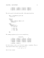
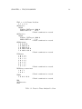
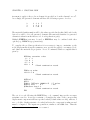
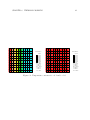
Additional commands may be used to output displacements and stresses.
7
8
9
21
16
4
6
5
22
17
2
3
24
18
25
19
11
1
20
15
6
1
23
2
12
13
14
7
8
9
3
4
10
5
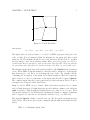
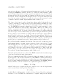
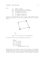
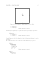
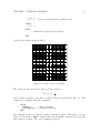
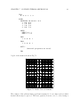
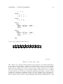
Figure 2.3: (a) 4-node mesh (b) 9-node mesh.
A rectangular region between 5 ≤ r ≤ 10 and 0 ≤ z ≤ 5 is used (Note that it is
important not to use a patch which includes a zero radius as no radial displacement is
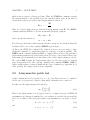
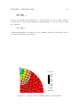
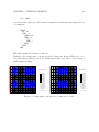
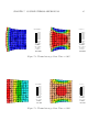
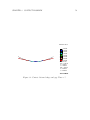
allowed there). The meshes shown in Fig. 2.3 are use for the patch tests and results for
the 9-node mesh are shown in Fig. 2.4 (results for a 4-node element are very similar).
Based on the above assessment we find that the element, as coded, passes the patch
DISPLACEMENT 1
6.00E+00
6.71E+00
7.43E+00
8.14E+00
8.86E+00
9.57E+00
1.03E+01
1.10E+01
Current View
Min = 6.00E+00
X = 5.00E+00
Y = 0.00E+00
Max = 1.10E+01
X = 1.00E+01
Y = 0.00E+00
Time = 0.00E+00
Figure 2.4: 9-node radial displacement contour.
test requirements for stability and consistency.