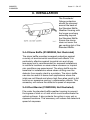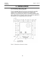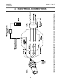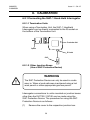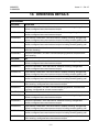
1
Operating Instructions
Searchpoint Optima Plus
Infrared Point Gas Detector
MAN0551
2108M0501
Issue 11 - 04-12
total environmental solutions
Ensure that you read and understand these Operating
Instructions BEFORE installing or operating any part of the
Searchpoint Optima Plus.
Please pay particular attention to the Safety Warnings.
Warnings
1. For installations in Europe, the Code of Practice
SELECTION, INSTALLATION AND MAINTENANCE
OF ELECTRICAL APPARATUS FOR USE IN
POTENTIALLY EXPLOSIVE ATMOSPHERES should
be strictly observed. General recommendations are
given in EN 60079-14:2008 & IEC 60079-14:2007.
Refer to EN 60079-29-2:2007 & IEC 60079-292:2007 in Europe or the appropriate local or
national regulations.
For installations in North America, the National
Electrical Code (NFPA 70 - 1990) or later issues
should be strictly observed.
Elsewhere the appropriate local or national
regulations should be used.
2. Operators must be fully aware of the action to be
taken if the gas concentration exceeds an alarm
level.
2
MAN0551
2108M0501
Issue 11 - 04-12
total environmental solutions
CAUTIONS
1. Use only approved parts and accessories with the
Searchpoint Optima equipment.
2. To maintain safety standards, a planned maintenance
programme is strongly recommended. This maintenance
programme should take account of all operational
conditions and requirements. Maintenance and service
operations should only be performed by personnel
qualified to work upon Searchpoint Optima Plus.
3. In order to maintain electrical safety, the unit must not be
operated in atmospheres with more than 21% oxygen.
IMPORTANT NOTICES
1. Honeywell Analytics Limited can take no responsibility
for installation and/or use of its equipment if this is not
done in accordance with the appropriate issue and/or
amendment of the manual.
2. The user of this manual should ensure that it is
appropriate in all details to the exact equipment to be
installed and/or operated. If in doubt, the user should
contact Honeywell Analytics Limited for advice.
3. If further details are required which do not appear in this
manual, contact Honeywell Analytics Limited or one of
their agents.
4. The Searchpoint Optima System is certified for and
intended for use in potentially hazardous areas. Install and
use the Searchpoint Optima System in accordance with
the latest regulations.
Every effort has been made to ensure the accuracy of this document,
however, Honeywell Analytics can assume no responsibility for any errors
or omissions in this document or their consequences.
Honeywell Analytics would greatly appreciate being informed of any errors
or omissions that may be found in the content of this document.
Honeywell Analytics Limited reserve the right to change or revise the
information supplied in this document without notice and without obligation
to notify any person or organisation of such revision or change.
3
MAN0551
2108M0501
Issue 11 - 04-12
CONTENTS
SectionPage
1.
INTRODUCTION
8
1.1General
8
2.
INSTALLATION VARIATIONS
12
2.1
ATEX Units
12
2.2
UL and CSA Units Only
13
3.
INSTALLATION
15
3.1Unpacking
15
3.2
Siting and Orientation
15
3.3
Installation Guide
16
3.4
Attachments and Options
20
3.4.1
General
20
3.4.2 Standard Weather Protection
20
3.4.3 Sunshade/Deluge Protection
20
3.4.4 Storm Baffle
21
3.4.5
Dust Barrier
21
3.4.6
Calibration Cap
22
3.4.7
Gassing Cover
22
3.4.8
Flow Housing
23
3.4.9 Remote Gassing Cell
24
3.4.10 Junction Box Adaptor Plate
25
3.4.11 European Duct Mounting Kit
26
3.4.12 US Duct Mounting Kit
29
4
MAN0551
2108M0501
Issue 11 - 04-12
CONTENTS
SectionPage
4.
ELECTRICAL CONNECTIONS
33
4.1General33
4.2
Analogue Connection
38
4.3
Digital Connection
38
4.4
+24V Power Connection
39
4.5
Earth Connection
39
5.COMMISSIONING
44
5.1General44
5.2
Commissioning Procedure using SHC-1
and Multimeter
45
5.2.1 Electrical Commissioning and Tests
45
5.2.2 Gas Response Testing
46
5.2.3 System Level Testing
47
5.2.4
Final Commissioning
5.3
49
Commissioning Procedure with Multimeter
Only
50
5.3.1 Electrical Commissioning and Tests
(Multimeter) Only
50
5.3.2 Gas Response Testing (Multimeter)
Only
52
5.3.3 System Level Testing
53
5.3.4 Final Commissioning (Multimeter)
54
5.4
Control System Setup
55
5.5
Functional Response Checking and
Calibration55
5
MAN0551
2108M0501
Issue 11 - 04-12
CONTENTS
SectionPage
6.CALIBRATION
57
6.1General
57
6.2
SHC-1 Hand-Held Interrogator
58
6.2.1 Connecting the Hand-Held
Interrogator
60
6.2.2 Hand-Held Interrogator Operating
Modes
62
6.2.3 Other Hand-Held Features
64
6.3
Calibrating the Controller
68
6.4
Calibrating the Sensor
71
7.
ROUTINE CHECKS
79
7.1General
79
7.2
Inspection and Functional Response Check
Procedure79
7.2.1 Response Check Using Gassing Cover
and %LEL Concentration Gas
81
7.2.2 Response Check Using Remote
Gassing Cell & High %v/v Gas
85
Inspection and Testing of Units Installed
in Ducts
90
Removal and Refitting of Flow Housing
92
7.4.1 Removal of Flow Housing
92
7.4.2 Refitting of Flow Housing
92
7.3
7.4
6
MAN0551
2108M0501
Issue 11 - 04-12
CONTENTS
SectionPage
8.
FAULT FINDING
95
8.1Troubleshooting
95
8.2
Diagnosis of Warning and Fault Messages 101
9.
REPLACEMENT OF HAND-HELD
INTERROGATOR BATTERY109
10.
ORDERING DETAILS
111
11.SPECIFICATION
115
11.1 Searchpoint Optima Plus Specification
115
11.2 Cross Interference to Other Gases and
Vapours122
11.3 Hand-Held Interrogator SHC-1
Specification
123
11.4 SHC Protection Device
124
11.5 Termination Unit DVC100 Specification
125
11.6 DX Termination Units Specification
126
12.
CERTIFICATION DETAILS
128
13.
WARRANTY
136
7
MAN0551
2108M0501
Issue 11 - 04-12
1. INTRODUCTION
1.1General
Searchpoint Optima Plus is designed for use in potentially
hazardous areas where it provides gas and vapour
detection which is free from poisoning and independent
of the presence of oxygen. The gas measuring parts of
Searchpoint Optima Plus are illustrated below.
Optical Block
Heater
Gas Measuring Path
Window
Heater
Mirror
Searchpoint Optima Plus uses the dual wavelength infrared
absorption principle to detect hydrocarbon gases and
vapours in various concentration ranges. The instrument
measures the number of molecules of the target gas in the
light path, which depends on the concentration of the target
gas. In addition to the relatively long and open measuring
chamber, Searchpoint Optima Plus can be fitted with a short
enclosed flow through-cell as part of the chassis.
This is fitted with separate inlet and outlet ports and
allows the application of high concentrations of gas for
test purposes.
8
MAN0551
2108M0501
Issue 11 - 04-12
1. INTRODUCTION
Searchpoint Optima Plus is a micro-processor controlled,
Infrared Gas Detector with comprehensive built-in selfdiagnostic and fault finding facilities. An analogue 4 to
20mA output and digital communications are provided as
standard. Full two way communication allows calibration
and advanced self checking procedures to be used. To take
advantage of these features a Hand-Held Interrogator unit
may be connected to a Termination Unit or via the SHC
Protection Device to other junction boxes.
There are several different types of termination unit available:
Termination Unit
Certification Output
DVC Type Termination Units
DVC100 (I) MK2
ATEX
Isolated 4-20mA
DVC100 (M) MK2
ATEX
Isolated 4-20mA and MODBUS
DX Type Termination Units
DVC100 (I)
UL
Isolated 4-20mA
DX100 (M)
UL
Isolated 4-20mA and MODBUS
Searchpoint Optima Plus contains no moving parts and
is available in a robust Stainless Steel explosion proof
enclosure which has a M25 (ATEX) or 3/4 NPT (UL and CSA)
mounting thread. The unit operates over a wide temperature
range and has a high degree of protection against dust
and water ingress. It is designed to operate in the most
arduous conditions and is supplied with a choice of weather
protection assemblies.
Searchpoint Optima Plus can be In-Duct Mounted, used
in Sampling Systems, is easily confidence checked and
may easily replace an existing sensor. Provided that
existing cabling has three appropriately rated cores and the
installation is correctly screened and earthed, it should not
be necessary to replace the field cables or junction boxes. (A
current to bridge converter may be required if the controller
cannot be configured to accept 4-20mA signals).
9
MAN0551
2108M0501
Issue 11 - 04-12
1. INTRODUCTION
No special tools are required for installation. Correct
function of the detector as installed can be easily confirmed
using a Hand-Held Interrogator. Maintenance amounts to
occasional cleaning, zeroing and response checking for
confidence.
10
MAN0551
2108M0501
Issue 11 - 04-12
11
MAN0551
2108M0501
Issue 11 - 04-12
2. Installation Variations
2.1ATEX Units
Existing Junction Box
Existing Cable
Optima
Replacing existing Sensor
using existing Junction Box
and Cable (where suitable).
Optima
New Junction Box.
New Installations.
Optima
DVC100
Optima
When used for calibration
and diagnostics purposes
the Hand-Held Interrogator
SHC-1 allows digital
communication with the
Optima. It is connected
to the Optima via the IS
Socket on the Termination
Unit DVC100 or via the
SHC Protection Device for
other junction boxes.
Optima
DVC Termination Unit
SHC-1
SHC-1
12
MAN0551
2108M0501
Issue 11 - 04-12
2. Installation Variations
2.2UL and CSA Units Only
3/4 NPT
Optima
UL and CSA Installations using
Explosion Proof Junction Box.
Note: The Junction Box must be suitable for the hazardous
location in which the Optima is installed, check with the
Junction Box manufacturers literature as to suitability of
the box.
Top
DX
Termination
Unit
Optima
Field
Cable /
Conduit
13
Handheld
Interrogator
Socket
MAN0551
2108M0501
Issue 11 - 04-12
14
MAN0551
2108M0501
Issue 11 - 04-12
3. INSTALLATION
WARNING
The Code of Practice regarding selection, installation
and maintenance of electrical apparatus for use in
potentially explosive atmospheres must be complied
with at all times.
Notes:1. The flying leads of the Searchpoint Optima Plus
must be mechanically protected and terminated
within a suitable terminal or junction facility.
2. When the detector is terminated in a hazardous
area a suitable UL listed enclosure must be used
(where appropriate).
3.1UNPACKING
Carefully unpack the equipment, observing any instructions
that may be printed on or contained in the packaging, and
check the contents for transit damage.
3.2 SITING AND ORIENTATION
Searchpoint Optima Plus must
be mounted horizontally, as
this greatly reduces the risk of
obscuration due to build up of
dirt and moisture on the optical
surfaces.
Ensure the area immediately
surrounding the sensor is free
from objects that could hinder
the free flow of air around it.
15
MAN0551
2108M0501
Issue 11 - 04-12
3. INSTALLATION
For monitoring lighter than air gases, Searchpoint Optima
Plus should be mounted above the area requiring protection.
For monitoring heavier than air gases it should be mounted
below the area to be protected.
When monitoring for heavier than air gases and mounting
the detector close to the floor, give consideration to the
potential of general site debris to build up on the detector.
Whether Searchpoint Optima Plus is installed in a
sheltered or an exposed location, it will require some form
of protection around the optics. The standard weather
protection combined with the sunshade/deluge protection
provides a high degree of protection of the detector, suitable
for many outdoor environments. Detectors operating in very
exposed locations where torrential rain or driven sea-spray
is routinely encountered can benefit from the additional
protection provided by the Storm Baffle (2108D0280).
In areas where a high pressure jet may be used at close
range to wash down the surrounding location, it is advisable
to fit some means of extra peripheral shielding, eg. Storm
Baffle or a shield plate.
Accessories and attachments that can be used to improve
ease-of-use, performance and reliability in particular
installations are described in Section 3.4.
3.3 INSTALLATION guide
Note: Installation of Searchpoint Optima Plus does not require
the unit to be opened. There are no user serviceable
parts inside the unit. Do not attempt to open or
dismantle the unit.
(1)
Ensure that the correct attachments and accessories
for the application have been fitted (see Section 3.4).
16
MAN0551
2108M0501
Issue 11 - 04-12
3. INSTALLATION
(2)
Check that the unit's 4-20mA current ouput is of the
correct type for the control card that it is connected to.
(Output type is on a label attached to white lead.)
Control card I/P: SINK
Control card I/P: SOURCE
(3)
Secure the junction box onto the mounting surface,
using the Junction Box Adaptor Plate if required.
Searchpoint Optima Plus must be installed with it's
long axis horizontal in order for the standard weather
protection to operate correctly and to prevent water
from settling on the optical surfaces (see below).
The Optima unit should therefore only be screwed into
a threaded entry that is in a vertical wall of the junction
box.
3
(4)
Optima O/P: SOURCE
Optima O/P: SINK
7
Feed the unit's wires carefully through the chosen
junction box entry and offer up it's threaded boss to
the entry. Screw the unit into the junction box until
it is secure and the semi-circular pattern of holes on
the front of the weather protection are on the bottom
(see below). For M25 entries, the boss should go right
through the wall and a locking nut should be fitted;
whilst for 3/4 NPT entries, the boss should lock off on
the taper. If getting the holes in the right orientation
requires more rotation than is readily achievable,
remove the weather protection and rotate it through
180 degrees.
17
MAN0551
2108M0501
Issue 11 - 04-12
3. INSTALLATION
(5)
Using a multimeter, check that the voltages on the
+24V, and 4-20mA connections with respect to 0V are
less than +32V DC and that there is no 110V or 230V
AC around.
(6)
Wire up the unit's electrical connections in
accordance with Section 4, taking note of the general
recommendations upon electrical installation.
(7)
Ensure that all cable entries are either used or plugged
in strict accordance with the relevant certification
requirements and local codes of practice.
(8)
Verify the correct installation and operation of the unit
using the SHC-1 handheld interrogator. If a Termination
Unit has been used, testing can be performed without
the need for a hot work permit. Alternatively, if a basic
junction box has been used, electrical connections can
be made to the terminals inside the box using the SHC
adaptor. This will ordinarily require a hot work permit.
CAUTION
1. Searchpoint Optima Plus is certified and specified
for operation in ambient temperatures from -40°C
to +65°C. Operation of the unit outside of this
temperature range invalidates the certification and
the warranty. The unit records a non-erasable fault
log entry if it is operated at temperatures outside of
it's certified range.
If the ambient temperature that the unit could be
exposed to is likely to go outside of the certified
range it is recommended that the unit be located
elsewhere. The use of sampling systems can be
highly effective, especially in applications where
high temperatures are involved.
18
MAN0551
2108M0501
Issue 11 - 04-12
3. INSTALLATION
2. Searchpoint Optima Plus is specified for operation
in environments where the rate of change of unit
temperature is less than 3°C / minute. Exceeding
this rate of change of temperature will cause the unit
to report a fault and may cause permanent damage.
If the conditions experienced by the unit are likely
to cause it to exceed this rate of change it is
recommended that additional preventative measures
are taken. The use of sampling systems is highly
effective; whilst shielding the unit from the prevailing
air flow can also be of benefit.
3. Searchpoint Optima Plus has been vibration tested
to the levels specified in EN60079-29-1. If the
vibration levels on the installation exceed this, the
unit's reliability and integrity of operation will be
degraded. Do not install units in locations where the
vibration exceeds this level.
4. All optical gas detectors are eventually affected by
the build up of contaminants / condensation upon
their optical surfaces, normally resulting in faults
or warnings. In order to minimise the faults and
warnings caused by this it is recommended that
detectors are located as far away as is possible
from sources of airborne contaminants and steam /
condensation. Alternatively, the fitting of shields or
the Storm Baffle (2108D0280) should be considered.
Sources of contamination / condensation that have
caused particular problems where appropriate
measures were not taken include generator / turbine
exhausts, steam lines / vents, drilling operation
(oilmist and mud spray) and unfiltered HVAC
installations. In dusty atmospheres, regularly check
for the build up of dust on the detector (refer to
section 7 Routine Checks).
19
MAN0551
2108M0501
Issue 11 - 04-12
3. INSTALLATION
3.4Attachments And options
3.4.1General
There are a number of attachments and accessories
available for use with Searchpoint Optima Plus. When
specifying Optima Plus for a particular application, it is
recommended that the user contacts Honeywell Analytics
or their representatives to determine the attachments and
accessories required. Covers, barriers and baffles provide
protection from a wide variety of environmental conditions.
Gassing covers, cells and flow housings provide the means
of applying gas to the detector. Mounting plates and remote
gassing kits enable the detector to be installed in ducts or in
places where obtaining routine access is difficult.
3.4.2Standard Weather Protection (2108D0276)
Provides the best compromise
between response time and
protection. Suitable for indoor,
outdoor and duct mounting
applications.
3.4.3Sunshade/Deluge Protection (2108D0275)
Supplied as standard
for all outside
applications. Provides
additional protection
against heavy rainfall,
wash downs and
direct sunlight.
20
MAN0551
2108M0501
Issue 11 - 04-12
3. INSTALLATION
The Sunshade/
Deluge protection
should be clamped
around the base of
the Standard Baffle
Weather Housing with
the longer overhang
extending beyond
the Standard Baffle.
Ensure the clamp
does not cover the
gas venting slot of the
Standard Baffle.
3.4.4Storm Baffle (2108D0280, Not Illustrated)
The storm baffle provides increased protection against
a variety of environmental conditions and effects. It is
particularly effective against torrential rain and driven
sea-spray and is recommended for exposed installations
in maritime locations or areas where monsoon or tropical
rain conditions are experienced. The storm baffle can be
beneficial in installations where steam drifting over the
detector from nearby plant is a problem. The storm baffle
can also be useful in some duct applications where the
inlets are not filtered and where high flow rates result in dirt
build-up or excessive cooling / condensation effects. This
accessory will reduce the detector’s speed of response.
3.4.5Dust Barrier (2108D0259, Not Illustrated)
Fits under the standard baffle weather housing to prevent
the ingress of dust or oil mist which could contaminate the
optical surfaces. It also protects the optics in very wet or
exposed locations. This accessory will reduce the detector’s
speed of response.
21
MAN0551
2108M0501
Issue 11 - 04-12
3. INSTALLATION
3.4.6Calibration Cap (2108D0272)
Used to achieve accurate
calibration of Optima Plus on the
bench. Requires all protective
covers and attachments to be
removed from the measurement
chamber except for the
dust barrier. The calibration
procedures are described in
Section 6.
CAUTION
The Calibration Cap is designed for temporary use on
Optima whilst performing calibration. If the calibration
cap is left fitted it will prevent ambient gas from reaching
the detector's measurement chamber. Ensure that
operators are aware that calibration caps must not be
left fitted. In order to reduce the likelihood of this mistake
going un-noticed, the calibration caps are coloured red.
3.4.7Gassing Cover (2108D0258)
Provides a convenient means
of applying gas to Optima Plus
units in the field. Suitable for
functional test and calibration
purposes. Fits over the standard
weather protection, covering the
gas inlet slots. Gas is introduced
into the weather protection via
an injection tube on the gassing
cover. Injected gas diffuses
through the dust barrier into the
measurement chamber.
The response check procedure
is described in Section 5.4.
22
MAN0551
2108M0501
Issue 11 - 04-12
3. INSTALLATION
CAUTION
The Gassing Cover is designed for field testing and
calibration operations. If the cover is left fitted it will
prevent ambient gas from reaching the detector's
measurement chamber. Ensure that operators are aware
that gassing covers must not be left on detectors.
Gassing covers are coloured red to reduce the likelihood
of this mistake.
3.4.8Flow Housing (2108D0282)
For use in sampling system
applications.
The Flow Housing is fabricated
from solvent resistant Anodised
Aluminium.
The nozzles on the Flow Housing
are stainless steel with an outside
diameter of 6mm.
It is advised that sample gases and vapours are sucked
(negative pressure) rather than blown (positive pressure)
through this housing and that sample flow rates do not
exceed 2 litres per minute.
It is recommended that a flow failure indicator is fitted
within the sampling system and the minimum flow rates are
suitable for the application and not less than 0.7 litres per
minute.
Note: response time will increase with a decreasing flow
rate.
The commissioning and calibration of an Optima equipped
with a flow housing is described in Sections 5 and 6.
23
MAN0551
2108M0501
Issue 11 - 04-12
3. INSTALLATION
3.4.9Remote Gassing Cell (2108B0240)
The Remote Gassing Cell (RGC) enables high
%v/v concentration gas to be applied remotely for
performing functional response checks (bump tests).
It is useful for units installed in ducts or in areas
where obtaining access is difficult. The RGC window
can be removed for cleaning.
Note:
During production, Optima Plus units are calibrated
with gas in the main measurement chamber, not in the
RGC. The RGC is not recommended for calibration
or high accuracy calibration testing purposes.
(The only exception to this is where units are being
used to measure high %v/v gases using the RGC as
a flow cell. In this instance, the units are production
calibrated with gas in the RGC.)
In order to avoid pressurisation effects, the flow rate should
be kept below 0.3 litres / minute.
The RGC option is factory fitted.
24
MAN0551
2108M0501
Issue 11 - 04-12
3. INSTALLATION
3.4.10 Junction Box Adaptor Plate (04200-A-1040)
The Junction Box Adaptor Plate provides a means of
increasing the spacing between the junction box's gland
entries and the mounting surface. This enables low gland
clearance junction boxes to be used without the Optima
Plus fouling on the wall / mounting surface. Junction boxes
which can be accommodated include the Hawke PL612 and
PJB1.
25
MAN0551
2108M0501
Issue 11 - 04-12
3. INSTALLATION
3.4.11 European Duct Mounting Kit (04200-A-1015)
This kit enables Optima Plus to be conveniently mounted
inside a duct. Electrical connections are made to the
detector via a junction box which is mounted outside of the
duct. Using this kit, test gas can be non-invasively applied to
the detector via the gassing points provided.
250
250
63
125
188
250
Note 1: Dimensions
shown in mm.
63
125
188
250
26
Note 2: The cutout
in the duct should be
230mm x 230mm.
MAN0551
2108M0501
Issue 11 - 04-12
3. INSTALLATION
Gassing
Points
Junction
Box
Searchpoint
Optima
Junction
Box
Bracket
Duct
Mounting
Plate
Notes: 1. In order to make use of the gassing points provided,
the Optima unit must be fitted with the Remote Gassing
Cell (2108B0240).
2. In offshore HVAC ducts or ducts without inlet
filtering, the use of the Storm Baffle (2108D0280) is
recommended.
3. CSA approval only applies for flow rates less than 5
m/s and does not cover the use of the Storm Baffle.
The duct mounting kit is assembled and installed onto a duct
as below:(1) Cut a square 230mm * 230mm hole in the duct wall. Drill
the holes required to attach the mounting plate to the duct
wall.
(2) Place the Optima unit on the side of the mounting plate
where the threaded bushes protrude and feed the wires
through the central hole.
27
MAN0551
2108M0501
Issue 11 - 04-12
3. INSTALLATION
(3) Locate the unit's boss in the central hole and feed the
unit's wires through the chosen cable entry on the junction
box.
(4) Screw the unit into the junction box until the assembly is
secure with the mounting plate trapped between the box and
the Optima.
(5) Cut off the seals on the ends of the gassing cell inlet
tubes.
(6) Attach the gassing tubing to the ends of the gassing cell
inlet tubes.
(7) Fasten the mounting plate to the wall of the duct,
ensuring that the seal is compressed.
(8) Wire up the unit in accordance with the electrical
connection details in Section 4.
(9) Ensure that all cable entries are either used or plugged in
strict accordance with the relevant certification requirements
and local codes of practice.
28
MAN0551
2108M0501
Issue 11 - 04-12
3. INSTALLATION
3.4.12 US Duct Mounting Kit
This kit enables Optima Plus to be conveniently mounted
inside a duct. Electrical connections are made to the
detector via a junction box which is mounted outside of the
duct. Using this kit, test gas can be non-invasively applied to
the detector via the gassing points provided.
Note 1: Dimensions shown in inches.
29
MAN0551
2108M0501
Issue 11 - 04-12
3. INSTALLATION
The duct mounting kit is assembled and installed onto a duct
as below:(1) Cut a square 6" x 6" hole in the duct wall. Drill the holes
required to attach the mounting plate to the duct wall.
(2) Remove the cover from the junction box.
30
MAN0551
2108M0501
Issue 11 - 04-12
3. INSTALLATION
(3) Feed the wires from the Searchpoint Optima Plus through
the weldment into the junction box. DO NOT SECURE THE
WIRES TO THE TERMINALS AT THIS TIME.
(4) Secure the sensor to the weldment.
(5) Attach the both tubing assemblies.
(6) Secure the mounting plate to the duct.
31
MAN0551
2108M0501
Issue 11 - 04-12
32
MAN0551
2108M0501
Issue 11 - 04-12
4. ELECTRICAL CONNECTIONS
CAUTION
The reliability and performance of instrumentation
installed at industrial and petrochemical facilities can
be strongly influenced by the design and quality of the
electrical installation. It is strongly recommended that
before designing an electrical installation for Searchpoint
Optima Plus the electrical installation design authority
reads Section 4.1.
4.1General
Searchpoint Optima Plus complies with the European
EMC requirements set out in standard EN50270. In order
to maintain compliance with these standards it is essential
that the electrical installation of Searchpoint Optima Plus is
engineered appropriately.
Electrical installation standards and practices vary for
different countries, companies and hazardous area
approvals. It is the responsibility of the electrical installation
design authority to determine the applicable standards
/ practices and ensure compliance with them. When
designing electrical installations for Searchpoint Optima
Plus it is recommended that the design authority considers
the following:a.
Ideally, the cases of units should not be connected
to electrically noisy (dirty) metalwork or conductors.
Preferably, the case (internally connected to the unit’s
green / yellow GND wire) should be connected to a
low noise instrument (clean) earth.
b.
Preferably, the field cable screen should be connected
to the unit’s green / yellow GND wire, providing a
single, continuous earth screen connected to a low
noise instrument (clean) earth. This connection must
33
MAN0551
2108M0501
Issue 11 - 04-12
4. ELECTRICAL CONNECTIONS
not be allowed to complete an earth loop or connect
instrument earth to safety earth.
c.
If armoured cable is being used it is necessary to
prevent safety (dirty) earth from becoming connected
to instrument (clean) earth via the continuity plate in
the field junction box. This is most easily achieved by
the use of insulating cable glands for the field cable
entry.
d.
For UL / CSA certified installations it is not practical to
isolate the unit’s case from safety (dirty) earth. The unit
and its junction box should be earthed in a manner
that complies with the certification requirements.
e.
Any earth / ground bonding arrangement employed
should ensure that the maximum peak voltage
between the unit’s case earth and any field cable
conductor is less than 350V. This includes conditions
where transient surge voltages are generated
by lightning or the switching of heavy electrical
plant. Surge voltages in excess of 350V can cause
permanent damage to the unit’s RFI filters and such
damage is not covered by warranty.
f.
Earthing / grounding arrangements that employ
multiple protective earths or earth grids significantly
increase the likelihood of large transient surge voltages
being generated between a unit’s case earth and the
field cable conductors.
g.
If it is suspected that the earth / ground bonding
arrangement employed will not prevent voltages
between the unit’s case earth and any field cable
conductor from exceeding 350V it is strongly
recommended that surge suppression devices be
installed close to the unit. Suitable, certified surge
suppression devices include MTL’s TP-48-I-NDI and
34
MAN0551
2108M0501
Issue 11 - 04-12
4. ELECTRICAL CONNECTIONS
Pepperl & Fuchs’ FN-LB-1. Two of these devices are
sufficient to provide protection of the +24V, 0V,
4-20mA and RS485 (A) connections to a unit.
h.
In general, correctly engineered star earthing
arrangements minimise earth current crosstalk and
noise, improving the reliability and performance of
instrumentation.
i.
Low noise instrument (clean) earth should only be
connected to safety earth (usually dirty) at a single
point on a site / installation. This connection should
be made in such a manner that it does not introduce
noise onto the instrument earth.
j.
The entire length of the field cabling connected to
a unit should be screened / shielded. This screen /
shield should be connected to a low noise instrument
(clean) earth at a single end. (The screen / shield can
be connected to the unit’s earth in the junction box,
provided that this is isolated from all other earths /
grounds.)
k.
For installations where the field cable conductors run
through conduit or armour connected to safety (dirty)
earth, the conduit or armour should not be considered
as a sufficient screen / shield. A separate cable screen
/ shield, connected to a low noise instrument earth
should be employed.
l.
The screens / shields of field cabling should not be
connected in a manner that creates earth loops or
that will result in the screens / shields carrying large
currents from heavy plant or equipment.
m.
The use of a single, screened / shielded cable for
each field device ensures good screening / shielding
and reduces crosstalk. Cabling arrangements that use
a single cable to connect a number of field devices
35
MAN0551
2108M0501
Issue 11 - 04-12
4. ELECTRICAL CONNECTIONS
compromise screening and increase the potential
for crosstalk. Such arrangements should only be
employed if the electrical installation design authority
is confident that this will not adversely affect the
reliability or performance of the system.
n.
Any electrical interference induced onto the
conductors of a 4-20mA loop by the installation must
be kept below the levels necessary to comply with
the general requirements of EN60079-29-1 or other
applicable gas detector performance requirements
/ standards. In practice, this means that peak noise
currents induced on the current loop should be no
greater than +/- 0.25mA. If peak noise currents larger
than this are induced on the current loop it is possible
that spurious gas readings, alarms and faults will be
reported by the control system monitoring the current
loop.
o.
The 0V rail of a control card / control system is often
connected directly to one side of the 4-20mA input’s
current sensing resistor. In such instances, any
electrical noise on the 0V rail can be considered to
be directly connected to the 4-20mA input. In order
to reduce the likelihood of such noise adversely
affecting the performance of a gas detection system it
is desirable to keep noise on the 0V rail to a minimum.
Safety earth / ground frequently carries a high level
of electrical noise and it is therefore advisable not to
connect the 0V rail to safety earth / ground. If the 0V
rail cannot be isolated from earth it is advisable to
either connect it to a low noise instrument (clean) earth
or through a path that presents a high impedance to
noise on the earth.
p.
For installations in Europe, all electrical equipment
connected to the system should comply with
EN50270. For non-European installations, electrical
equipment connected to the system should comply
36
MAN0551
2108M0501
Issue 11 - 04-12
4. ELECTRICAL CONNECTIONS
with applicable national or international EMC
standards.
q.
Searchpoint Optima Plus is designed to operate
correctly with supply voltages down to 18V. When
supplied with 18V, the maximum current drawn
by a single Searchpoint Optima Plus unit will be
250mA. The field cabling conductors should have
sufficient cross sectional area to ensure that when
a unit is drawing 250mA the voltage reaching it does
not fall below 18V. For a control room voltage of 24V,
the maximum round loop cable resistance must therefore be 24 Ohms. Round loop cable resistances
greater than those necessary to ensure that units always receive at least 18V may result in unreliable
operation.
r.
Ideally, the 24V supply reaching units should be free
from large transients, fluctuations or high frequency
noise. Transients or fluctuations which take the
supply voltage outside of the 18-32V range may
result in units switching off and re-booting.
s.
In order to reduce the likelihood of radio frequency
interference affecting the operation of units it is
recommended that neither units nor their cabling
are installed in close proximity to the antennae of
37
MAN0551
2108M0501
Issue 11 - 04-12
4. ELECTRICAL CONNECTIONS
high powered radio, radar or satellite communication
equipment.
4.2Analogue connection
The unit’s analogue 4-20mA output is non-isolated and
shares the 0V return (black wire) connection with the DC
supply to the unit. The 4-20mA output is factory configured
for current source or current sink. The configuration is
identified by a label on the white 4-20mA output wire. The
connections to the unit are shown in the following figures.
Note: If using Searchpoint Optima Plus to replace an existing
catalytic sensor, a Current to Bridge converter must be
used.
4.3 Digital Connection
Searchpoint Optima Plus has a built-in RS485 digital
communications link. When using Termination Units, this link
38
MAN0551
2108M0501
Issue 11 - 04-12
4. ELECTRICAL CONNECTIONS
can be connected to using the IS socket. For other junction
boxes, this link can be connected to using the SHC
Protection Device between the junction box terminals and
the SHC-1 Handheld Interrogator.
The RS485 communications link is connected to the unit’s
orange (RS485(A)) and blue (RS485(B)) wires. If not used,
these wires must be separately terminated in a suitable
terminal or junction facility.
4.4 +24V POWER CONNECTION
The +24V DC power supply feed should be connected to the
unit via the red (+24V) and black (0V return) wires.
4.5EARTH CONNECTION
An earth connection can be made to the unit in a number of
ways. When deciding how to earth the unit, consideration
should be given to the recommendations in section 4.1.
Physically, the earth connection can be made either via
the unit’s green/yellow earth wire, a metal nut between the
unit and the junction box’s earth continuity plate or a wire
connected to the unit’s external earthing point.
39
Minimum Configuration for Retrofit Application (Optional Current to Bridge Converter)
MAN0551
2108M0501
Issue 11 - 04-12
4. ELECTRICAL CONNECTIONS
40
41
SHC-1
(refer to individual Terminal Unit manuals
for specific electrical connections
Termination Unit
Configuration for Termination Unit with IS Socket and Hand-Held Interrogator
IS
Socket
Optional Modbus Output
(M version only)
MAN0551
2108M0501
Issue 11 - 04-12
4. ELECTRICAL CONNECTIONS
Standard Configuration for Retrofit Application (With SHC Protection Device and Hand-Held Interrogator Option.)
MAN0551
2108M0501
Issue 11 - 04-12
4. ELECTRICAL CONNECTIONS
42
MAN0551
2108M0501
Issue 11 - 04-12
43
MAN0551
2108M0501
Issue 11 - 04-12
5. COMMISSIONING
5.1General
Warnings
1. Alarm level signals may be intentionally generated
during the commissioning procedure. Ensure
that appropriate steps are taken to prevent the
unintended sounding of alarms or executive
actions. It is recommended that the control card
corresponding to the detector is isolated or inhibited
during the majority of the commissioning procedure.
2. In order to commission units installed with basic
junction boxes (i.e. not DVC100 or DX100), it will be
necessary to open the junction boxes under power.
This will require the appropriate safe operating
procedures to be employed.
3. The Optima Plus commissioning procedure
is best performed using an SHC-1 Handheld
Interrogator and a digital multimeter. Use of the
SHC-1 interrogator in combination with a multimeter
enables more comprehensive checks and testing
(Section 5.2). If however, an SHC-1 interrogator
is not available, basic commissioning can be
performed using just a multimeter (Section 5.3).
IMPORTANT
Searchpoint Optima Plus is supplied calibrated and
ready for use. It does not require calibration during
commissioning. Reference is made in this section to
a Gas Response Test. This is not a full calibration of
the sensor where zero and span values are set, but a
response test using a known concentration of gas to
validate the calibration of the sensor.
44
MAN0551
2108M0501
Issue 11 - 04-12
5. COMMISSIONING
5.2 COMMISSIONING PROCEDURE USING
SHC-1 AND MULTIMETER
5.2.1 Electrical Commissioning and Tests
(SHC-1 & Multimeter)
The procedure for verifying the electrical installation of the
unit is described below:(1)
Before applying power to the unit, ensure that the field
wiring is correct and all electrical connections are in
accordance with Section 4.
(2)
Check that the unit’s 4-20mA output configuration is
correct for the type of control card that it is connected
to. (Source output for sink input, sink output for source
input. Unit’s output configuration is on label attached
to white wire.)
(3)
Apply power to the control card connected to the unit
being commissioned. Wait for 1 minute to allow the
unit to initialise and stabilise. Using a multimeter set
on dc volts, measure the voltage across the red (+24V)
and black (0V return) connections. Nominally, this
voltage should be +24V. Voltages in the range +18V to
+32V are acceptable.
(4)
Using either the IS socket on the Termination Unit,
or the SHC Protection Device, connect the SHC-1
Handheld Interrogator to the unit’s RS485 comms
link.(See Section 4.2 for SHC Protection Device
connections.)
(5)
Select the DIAGNOSTICS option on the interrogator
menu and instruct the unit to display any ACTIVE
WARNINGS or ACTIVE FAULTS. (Diagnosis of FAULT /
WARNING codes is described in Section 8.)
45
MAN0551
2108M0501
Issue 11 - 04-12
5. COMMISSIONING
a. If there are any ACTIVE FAULTS, the cause(s) of
these must be identified and remedied before the
unit will become fully operational.
b. If there are any ACTIVE WARNINGS, the unit can
operate correctly despite the warning(s). However,
for reliable long term operation it is strongly
recommended that problems causing warnings are
fixed before a unit is fully commissioned.
5.2.2 Gas Response Testing (SHC-1 & Multimeter)
The procedure for testing gas response as part of the
commissioning process is described below:(1)
Select the DISPLAY mode on the SHC-1 Handheld
Interrogator. Check that the displayed gas reading
is 0.0% LEL. If the displayed gas reading is not
0.0% LEL, check that their is no background gas
concentration present, the optics are clean and free
from condensation and that the unit has been given
sufficient time to stabilise in it’s intended operating
environment. (For best results, it is recommended
that a unit is left powered up for one hour before
performing zero or span calibration / test activities.)
(2)
Using the SHC-1 interrogator, put the detector into
INHIBIT (this will prevent gas readings from being
signalled on the 4-20mA output).
(3)
Making use of either the gassing cover, or the remote
gassing cell (where fitted), perform a functional gas
test. The procedure for performing functional gas
tests is detailed in Section 5.5. For a nominal 50%
LEL test gas concentration, the displayed reading
should be between 45% LEL and 55% LEL. (If
necessary, test gas concentrations between 20%LEL
and 95%LEL can be used with the same +/- 5% LEL
test tolerance.)
46
MAN0551
2108M0501
Issue 11 - 04-12
5. COMMISSIONING
Provided the displayed gas reading falls within the +/-5%
LEL test tolerance range, the functional gas test has been
completed satisfactorily.
CAUTION
If the displayed gas reading is not as expected, do not
proceed to re-calibrate the unit immediately. Instead,
double check the unit’s zero, the test gas and the gassing
technique. (IR gas detectors do not exhibit significant
span drift and in most instances, any problem will be with
the zero or the test gas / technique.) Only consider
re-calibrating a unit when certain that the zero, test gas
and technique are correct and that the unit’s gas response
is significantly out. The calibration technique is detailed in
Section 6.3.
5.2.3 System Level Testing (SHC-1 & Multimeter)
Confirmation of correct operation of the complete gas
detection system can be done using either test gas at the
required concentrations (Option B) or by FORCEing the
unit’s 4-20mA output under control of the SHC-1 interrogator
(Option A):-
CAUTION
When performing system level tests, ensure that any
resulting alarms or executive actions will not give rise to
unintended emergency drills or loss of production /
shut-down.
Note: It is assumed that the control system has been set up
for currents of 4mA and 20mA to read 0.0% LEL and
100% LEL respectively. If necessary, the FORCE 4-20mA
option can be used for setting up the control card. Be
aware that a 10 minute timeout applies to FORCE’d
4-20mA outputs.
47
MAN0551
2108M0501
Issue 11 - 04-12
5. COMMISSIONING
Option A) System Test Using FORCE’d 4-20mA
(1)
The easiest way of performing system level functional
tests is to use the SHC-1 interrogator to FORCE the
4-20mA output to currents that are just above the
relevant alarm thresholds.
(2)
The FORCE 4-20mA option is available from the
CALIBRATE menu. Using this option, FORCE the
4-20mA output to a current just above the A1 alarm
threshold. For example, with an A1 of 20% LEL, a
current of 7.5mA should suffice. Verify that the system
reports and responds as intended to this A1 signal.
(3)
FORCE the 4-20mA output to a current just above the
A2 alarm threshold. With an A2 of 60% LEL, a current
of 14mA should suffice. Verify that the system reports
and responds correctly to this A2 signal.
(4)
RELEASE the 4-20mA output. Confirm that the
system returns to normal, with no active alarms or
faults.
Option B) System Test Using Gas
If system level functional tests must be performed using gas,
test gas concentrations at least 5% LEL (ideally 10% LEL)
above each alarm threshold are required in order to allow for
system tolerances.
(1)
Using either the gassing cover or the remote
gassing cell, apply test gas to the detector at the
concentration required to reliably exceed the A1
alarm threshold. For example, with an A1 alarm
threshold of 20% LEL, the minimum nominal test gas
concentration should be 25% LEL (ideally 30% LEL).
Verify that the system responds as intended to an A1
signal generated in this manner.
48
MAN0551
2108M0501
Issue 11 - 04-12
5. COMMISSIONING
(2)
Apply test gas at the concentration required to reliably
exceed the A2 alarm threshold. With an A2 alarm
threshold of 60% LEL, the minimum nominal test gas
concentration should be 65% LEL (ideally 70%LEL).
Verify that the system responds correctly to an A2
signal generated in this manner.
5.2.4 Final Commissioning (SHC-1 & Multimeter)
The commissioning process is finished off as described
below:(1)
Remove or disconnect any gas testing equipment
from the unit.
(2)
Ensure that any test gas used is fully vented from the
measurement chamber or gassing cell. Verify that the
displayed gas reading returns to zero. (If the remote
gassing cell has been used, ensure that once vented,
it’s inlet tubes are sealed with the protective caps
provided (or a suitable alternative).)
(3)
If required, remove the detector from INHIBIT.
(4)
Select DIAGNOSTIC mode and verify that the unit has
no ACTIVE FAULTs or ACTIVE WARNINGs.
(5)
Disconnect the SHC-1 interrogator. Replace the
junction box lid (where removed).
(6)
When all of the relevant steps above are completed
satisfactorily, the unit has been commissioned and is
ready for operational use.
49
MAN0551
2108M0501
Issue 11 - 04-12
5. COMMISSIONING
5.3 COMMISSIONING PROCEDURE WITH
MULTIMETER ONLY
5.3.1Electrical Commissioning and Tests
(Multimeter) Only
The procedure for verifying the electrical installation of the
unit is described below:(1)
Before applying power to the unit, ensure that the
field wiring is correct and in accordance with
Section 4.
(2)
Check that the unit’s 4-20mA output configuration
is correct for the type of control card that the unit
is connected to. (Source output for sink input,
sink output for source input. The unit’s output
configuration is on a label attached to the white wire.)
(3)
Apply power to the control card connected to the unit
being commissioned. Wait for 1 minute to allow the
unit to initialise and stabilise. Using the multimeter
set on dc volts, measure the voltage across the red
(+24V) and black (0V return) connections. Nominally,
this voltage should be +24V. Voltages in the range
+18V to +32V are acceptable.
(4)
Remove power from the unit.
(5)
Insert the multimeter set to read current (mA) in series
with the 4-20mA loop as follows:-
a. Current Sink Output
Remove the unit’s white 4-20mA output wire from
the terminal for the 4-20mA loop connection.
Connect the multimeter’s negative probe to the
white 4-20mA wire. Connect the multimeter’s
positive probe to either the +24V terminal or the
4-20mA loop terminal.
50
MAN0551
2108M0501
Issue 11 - 04-12
5. COMMISSIONING
b. Current Source Output
Remove the unit’s white 4-20mA output wire from
the terminal for the 4-20mA loop connection.
Connect the multimeter’s positive probe to the
white 4-20mA wire. Connect the multimeter’s
negative probe to either the 0V terminal or the
4-20mA loop terminal.
(6)
Apply power to the unit and monitor it’s 4-20mA
output to confirm that it executes the correct powerup sequence as below:-
a. Output current of 0.0mA (0.0 to 0.5mA) for a period
of approximately seven seconds.
b. Output current of 2mA (INHIBIT current, 1.8 to
2.2mA) for a period of up to one minute whilst the
unit initialises and stabilises.
c. Output current of 4mA (ACTIVE zero gas current,
3.8mA to 4.2mA), which indicates that the unit is
operational and reading 0.0% LEL gas.
Note: If the unit is powered up in a non-zero
gas concentration, it will output a signal
corresponding to the gas concentration.
51
MAN0551
2108M0501
Issue 11 - 04-12
5. COMMISSIONING
5.3.2Gas Response Testing (Multimeter) Only
CAUTION
Without the SHC-1 interrogator it is not possible to
INHIBIT the gas detector. To avoid unintended executive
actions or alarms, it is recommended to either isolate
the detector itself or inhibit / isolate the corresponding
control card.
Functional gas testing can be performed using the
multimeter to monitor the 4-20mA output:(1)
Isolate the detector by disconnecting the 4-20mA
output from the loop terminal and connecting the
multimeter to measure the 4-20mA current to either
the +24V (for current sink) or 0V (for current source).
Alternatively, if the control card has been isolated /
inhibited, connect the multimeter in series with the
4-20mA loop.
(2)
Making use of either the gassing cover, or the remote
gassing cell (where fitted), perform a functional gas
test as detailed in Section 5.5.
CAUTION
If the 4-20mA current is not as expected, double check
the unit’s zero, the test gas and the gassing technique.
(IR gas detectors do not exhibit significant span drift and
in most instances the problem is with the zero or the
test gas / technique.) Only consider re-calibrating a unit
when certain that the zero, test gas and technique are
correct and that the unit’s gas response is significantly
out. The calibration procedure is detailed in Section 6.3.
52
MAN0551
2108M0501
Issue 11 - 04-12
5. COMMISSIONING
For a nominal 50% LEL test gas concentration, the
4-20mA output current should be between 11mA and 13mA.
If the measured current falls within the correct range, the
functional gas test has been completed satisfactorily.
Note: Zeroing and calibration activities require use of the
SHC-1 interrogator.
5.3.3System Level Testing (Multimeter)
If it is necessary to confirm the correct operation of the
complete gas detection system during commissioning
(without an SHC-1 interrogator), this can only be done using
test gases at concentrations which are at least 5% LEL
(ideally 10% LEL) above the relevant alarm thresholds.
(1)
Remove power from the unit. Reconnect the unit’s
4-20mA output to the appropriate loop terminal (the
multimeter should still be in series to measure current).
(2)
Making use of either the gassing cover, or the
remote gassing cell (where fitted), introduce gas at
the required A1 test concentration into the unit. For
example, with an A1 alarm threshold of 20% LEL, the
minimum test gas concentration required is 25% LEL.
The corresponding 4-20mA output current should be
between 7.2mA and 8.8mA. Confirm that the correct
current and system responses are observed when the
A1 test gas is introduced into the unit.
(3)
Introduce gas at the required A2 test concentration
into the unit. With an A2 alarm threshold of 60% LEL,
the minimum test gas concentration required is 65%
LEL. The corresponding 4-20mA output current should
be between 13mA & 15mA. Confirm that the correct
current and system responses are observed when the
A2 test gas is introduced into the unit.
53
MAN0551
2108M0501
Issue 11 - 04-12
5. COMMISSIONING
5.3.4Final Commissioning (Multimeter)
The commissioning process is finished off as described
below:(1)
Remove or disconnect any gas testing equipment
from the unit.
(2)
Ensure that any test gas used is fully vented from the
measurement chamber or gassing cell. (If the remote
gassing cell has been used, ensure that once vented,
it’s inlet tubes are sealed with the protective caps
provided (or a suitable alternative)).
(3)
Verify that after the initialisation and stabilisation
period (approximately 1 minute), the 4-20mA output
returns to 4mA nominal (between 3.8mA and 4.2mA).
(4)
Remove power from the unit and disconnect the
multimeter from the 4-20mA loop. Connect the white
4-20mA wire back directly to the loop terminal.
Re-apply power to the unit.
(5)
Verify that the unit returns to ACTIVE status and that
the gas reading displayed on the control card is
0.0% LEL.
(6)
Replace the junction box lid.
(7)
When all of the relevant steps above are completed
satisfactorily, the unit has been commissioned and is
ready for operational use.
54
MAN0551
2108M0501
Issue 11 - 04-12
5. COMMISSIONING
5.4 Control system setup
If the controller is in need of setting up, ie. for a 4 to 20mA
signal to show an equivalent reading eg. 0 - 100% fsd, this
may be done in two ways:
i)
By using the Hand-Held Interrogator to FORCE the
required signal to the controller (see Section 6.3 of
this manual)
or
ii)
With calibration gas applied to the sensor.
In each of these cases, a known signal is sent to the
controller, and the controller is set to show the equivalent
signal.
5.5 Functional Response Checking and
Calibration
Searchpoint Optima Plus is supplied factory calibrated and
when commissioning a unit, all that should be required to
verify correct operation is a functional response check.
The procedure for functional response checking is described
in Section 7 Routine Checks.
Where local regulations or working practices require gas
detectors to be calibrated when they are commissioned,
this should be performed in accordance with the procedure
described in Section 6 Calibration.
55
MAN0551
2108M0501
Issue 11 - 04-12
56
MAN0551
2108M0501
Issue 11 - 04-12
6. Calibration
6.1general
Searchpoint Optima Plus is supplied factory calibrated for
a particular hydrocarbon gas (approximately 100 different
gas calibrations are currently available). Properly installed
and maintained, Optima Plus does not require routine
calibration. This operational benefit is made possible
by the inherent stability of the IR absorption process
and the fully compensated optical configuration used.
In order to maintain confidence in the continued correct
operation of fielded Optima Plus units it is recommended
that a functional gas test is incorporated into the planned
maintenance procedure for the unit. In most applications
and installations, a planned maintenance / service interval
of 1 year is appropriate, although this will depend upon site
conditions and requirements. EN60079-29-2 and national
regulations should be observed.
Where site operating procedures or regulations require
routine calibration of gas detectors, this is possible using
the SHC-1 Handheld Interrogator and the gassing cover.
Care needs to be taken in order to ensure that routine
field calibrations do not reduce the calibration accuracy
compared to the original factory calibration. (Factory
calibration is performed in more controlled conditions than
are readily achievable in the field.)
Functional gas testing and calibration are made considerably
easier by use of the SHC-1 Handheld Interrogator. If an
SHC-1 is not available, basic functional gas testing can be
performed using just a multimeter to monitor the 4-20mA of
the unit being tested.
CAUTION
Searchpoint Optima Plus is a robust, flammable gas
detector, it is not an analyser. Where the performance or
features of an analyser are required, an analyser should
be used.
57
MAN0551
2108M0501
Issue 11 - 04-12
6. Calibration
6.2 SHC-1 HANDHELD INTERROGATOR
The SHC-1 Handheld Interrogator is a portable, Intrinsically
Safe (IS) device which can be used to calibrate, test and
commission all of Honeywell Analytics Searchpoint and
Searchline optical gas detection products. The SHC-1
interrogator communicates with detectors via a digital RS485
link. Electrically, this link can be made either by using the IS
socket on the DVC100 / DX100 or by connecting the flying
leads on the SHC Protection Device (04230-A-1025) to the
appropriate junction box terminals.
WARNING
The IS certification of the SHC-1 Handheld Interrogator
only remains valid if it is used in conjunction with the
Termination Unit or the SHC Protection Device. Do not
attempt to connect the SHC-1 interrogator directly to
units, always use either the Termination Unit or the SHC
Protection Device.
Press ↵ and hold for three
seconds to switch on.
LCD Display
Push Buttons
Hand-Held
Interrogator
Type SHC-1
58
Press ↵ and esc together
and hold to switch off.
Unit powers down
auto-matically after
10 minutes to prolong
battery life.
MAN0551
2108M0501
Issue 11 - 04-12
6. Calibration
6.2.1Connecting the SHC-1 Hand-Held Interrogator
6.2.1.1 Termination Units
When using a Termination Unit, the SHC-1 Handheld
Interrogator can be directly connected to the IS socket on
the bottom of the Termination Unit.
Termination Unit
Optima
IS Socket
SHC1
6.2.1.2 Other Junction Boxes
(Use of SHC Protection Device)
Warning
The SHC Protection Device can only be used in a safe
area. ie. When a local safe area is achieved using a hot
work permit or other appropriate gas free permit.
Interrogator connections to units mounted on junction boxes
other than the DVC100 / DX100 can be made using the
SHC Protection Device. The procedure for using the SHC
Protection Device is as follows:(1)
Remove the cover to the respective junction box.
59
MAN0551
2108M0501
Issue 11 - 04-12
6. Calibration
(2)
Connect the brown lead of the SHC Protection Device
to the orange lead of the Optima communications link.
(3)
Connect the blue lead of the SHC Protection Device to
the blue lead of the Optima communications link.
(4)
Connect the Hand-Held Interrogator SHC-1 to the
SHC Protection Device connector.
Note: When transporting the SHC Protection Device in a
hazardous area, the SHC Protection Device must be
disconnected from the Hand-Held Interrogator.
To Optima
Communications
Link Connections
in Junction Box
brown
To Hand-Held
Interrogator
SHC-1
blue
SHC Protection Device
6.2.2Hand-Held Interrogator Operating Modes
The Hand-Held Interrogator version 4v0 is compatible
with Searchpoint Optima, Searchpoint Optima Plus and
Searchline Excel. To work with a specific product the correct
operating mode has to be selected as follows:
(1)Press ↵ to switch on the power.
(2)
The display will first show a title screen:
Z - SHC 1 Optima
Interrogator 4v0
The current operating mode is shown in the top right
of the display.
(3)Press esc and the display will show:
Z - SHC 1 Optima +
Interrogator 4v0
60
MAN0551
2108M0501
Issue 11 - 04-12
6. Calibration
(4)Press esc again and the display will show:
Z - SHC 1 Excel
Interrogator 4v0
If esc is pressed again the operating mode will
change to Optima and the different modes can be
stepped through again.
(5)
When the display shows Optima + as the operating
mode wait three seconds for the main menu to be
displayed:
Main
Display
Note: 1. The current operating mode is remembered when
the Hand-Held is switched off.
2. The operating mode can also be changed by
selecting the change mode option on the main menu.
(6)Press
(7)Press
(8)Press
and the display will show:
Main
Calibrate
and the display will show:
Main
Diagnose
and the display will show:
Main
Gas Tables
61
MAN0551
2108M0501
Issue 11 - 04-12
6. Calibration
(9)Press
(10)Press
(11)Press
and the display will show:
Main
Configure and the display will show:
Main
Change Mode
and the display will show:
Main
62
Power Off
Main
Display
Interrogator 4v0
Z- SHC1 Optima +
Calibrate
63
Select Gas
Gas Tables
Show Library
Gas Tables
Show Gas
Gas Tables
Gas Tables
Main
Change Mode
Main
Configure Main
Power Off
Main
This diagram shows all the Hand-held Interrogator
Software features. Use of the and keys to display
the individual menu options. The options are selected
by pressing ↵ and exited by press esc.
Soft Reset
Diagnose
Self Test
Diagnose
Active Warns
Diagnose
Active Faults
Diagnose
Diagnose
Main
SHC-1 Hand-held Calibrator Menu Structure
Normal 4-20
Calibrate
Force 4-20
Calibrate
Cal Sensor
Calibrate
Display
Calibrate
Main
MAN0551
2108M0501
Issue 11 - 04-12
6. Calibration
MAN0551
2108M0501
Issue 11 - 04-12
6. Calibration
6.2.3Other Hand-Held Features
6.2.3.1Display
Selecting this option from the main menu displays:
Optima + Methane
xx.x % LEL
The display shows the gas type, the gas reading and in the
bottom right a status indicator:
F
indicates an active fault condition.
W
indicates an active warning.
Rotating bar indicates a healthy active unit.
A
indicates a gas concentration in excess of the units internal alarm threshold
O
indicates an active overrange.
I
indicates inhibit condition.
Pressing
or ↵ changes the display to show:
Optima + S/W
4v0
The version of software currently installed within the
Searchpoint Optima Plus unit.
Pressing
,
or ↵ will return the display to showing the
current gas reading.
Pressing esc exits the display option to the main menu.
64
MAN0551
2108M0501
Issue 11 - 04-12
6. Calibration
6.2.3.2Calibrate
Display
The Display option on the Calibrate menu provides the same
information as the Display option on the Main menu except
the analogue output will be inhibited. This function is useful
if a response check is to be carried out and you do not wish
the gas reading to be reported on the analogue output.
Note: The rotating bar will not be shown on the gas reading
display when the analogue output is inhibited.
Normal 4-20
This action releases the analogue output. It should be
used if a communication error occurs while performing an
operation with the Hand-Held which Inhibited the analogue
output.
Note: The unit will release its analogue output automatically 10
minutes after it was Inhibited if no digital communication
occurs.
6.2.3.3Diagnostics
Active Faults/Active Warning
Selecting one of these actions displays any fault or warning
conditions which are present in the unit. If more than one
condition is simultaneously present, these may be scrolled
through by pressing the
or
keys.
FAULT conditions prevent the unit from working as a gas
detector and are always signalled on the analogue output as
0mA.
65
MAN0551
2108M0501
Issue 11 - 04-12
6. Calibration
WARNING conditions indicate that the unit is operating
close to the limits of its specified operating envelope. The
unit may go into fault in the near future. If a fault condition
is present in the unit while the active warnings are being
displayed, the top line of the display will show Fault Present.
Correct the Fault condition first.
A list of fault and warning conditions and the actions
which should be taken to correct the problem are given
in section 8.
Self Test
This action instructs the unit to complete a self test cycle. If
a fault or warning condition was found in the unit, the HandHeld display will show:
Error 13
Error in Unit
Details of the fault or warning can be viewed by selecting
the Active Fault/Active Warning menu option.
Soft Reset
Selecting this option forces the unit to reboot. It is
equivalent to switching the power to the unit off and
then on.
6.2.3.4Gas Table
The Show Gas menu option displays the current gas type.
The Show Library action displays the part number and issue
of the data base within the unit which contains the details of
the diferent gasses which can be detected.
The Select Gas menu option allows the gas type of the unit
to be changed. The gas types available on the standard
unit are listed in Section 11.1.
The unit is inhibited while this action is performed. The unit
should be calibrated after the gas type is changed.
66
MAN0551
2108M0501
Issue 11 - 04-12
6. Calibration
6.2.3.5Config
The Show Config option on the Config menu shows the
values of a number of key paramaters in the Searchpoint
Optima Plus. These may be scrolled through by pressing the
or
keys.
Optima Plus Configuration Parameters
Configuration
Parameters
Parameter
Title
Purpose
Auto Zero
Zero
Tracking
Enables automatic zero tracking
function within the unit. Used only
in specialist applications, function
is normally disabled.
Alarm
Threshold
Alarm
Threshold
Sets a gas concentration threshold (adjustable over the range
10% to 50% full scale, default
25%) beyond which the unit
considers a dangerous level of
gas is present. A fault will be
signaled if the output current can
not be driven to a value in excess
of this threshold.
Inhibit
Current
Inhibit mA
Defines the output current for
Inhibit condition.
Warning
Current
Warning mA
Defines the output current when a
warning is present.
Overrange
Current
Overrange mA
Defines the output current when
the gas concentration exceeds
full scale.
Protocol
Address
Digital
Address
Defines the protocol address of
the unit when connected into a
multi-drop digital network.
Used only in specialist
applications.
6.2.3.6Power Off
Entering this menu and pressing ↵ turns off the Hand-held
Interrogator to preserve battery life.
67
MAN0551
2108M0501
Issue 11 - 04-12
6. Calibration
6.3 Calibrating the controller
This procedure allows the user to calibrate the controller by
FORCE’ing a known current out of the unit’s 4-20mA output.
Use of this technique enables calibration of the controller’s
0-100% fsd scale without the need for gas. The output can
be forced in the range 1.0 to 21mA (0.1mA resolution).
It is recommended that calibration of the controller is
performed at two points, ideally 4mA (0.0% fsd) and 12mA
(50% fsd). Provided that no background gas concentration
is present, the unit’s 4mA (0.0% fsd) output can be used to
calibrate the control cards zero point. The span calibration
of the controller can then be calibrated by FORCE’ing the
required current as follows:(1)
Connect the Hand-Held Interrogator to the unit.
(2)Press ↵ to switch the power on, ensure the Hand-held
is in Optima + mode and wait five seconds.
The display will show:
(3)Press
Main
Display
and the display will show:
Main
Calibrate
(4)Press ↵ and the display will show:
Calibrate
Display
68
MAN0551
2108M0501
Issue 11 - 04-12
6. Calibration
(5)Press
and the display will show:
Calibrate
Cal Sensor
(6)Press
and the display will show:
Calibrate
Force 4-20
This selects the FORCE'd 4-20mA routine which can
be used to calibrate the controller.
(7)Press ↵ and the display will show:
O/P 4-20 current
4.0 mA
(8)Press or
to change the displayed mA value in
0.1mA steps:
O/P 4-20 current
12.0 mA
Choose the desired value.
(9)Press ↵ and the display will show:
Fixed: nn.nn mA
Press enter
where nn.nn is the current measured by the Optima
Plus diagnostic function. The analogue output is now
set to the selected value set in step (8). Specified
accuracy is ±1% FS (±0.2mA).
69
MAN0551
2108M0501
Issue 11 - 04-12
6. Calibration
(10) Calibrate the controller to display the correct reading
for the current being FORCE'd on the 4-20mA output.
(11)Press ↵ and the display will show:
Press Enter To
Release 4 - 20
Note: The unit will return to normal operation after 10 minutes
if no key is pressed.
(12)Press ↵ and the display will show for 3 seconds:
4 - 20 Released
(13)
The analogue output has now returned to normal
operation.
Wait and the display will show:
Calibrate
Force 4-20
Returns to the Calibrate Menu.
(14)Press esc twice to return to the Main Menu:
Main
Display
(15) The Hand-Held Interrogator may be switched off by
pressing esc and ↵ together.
70
MAN0551
2108M0501
Issue 11 - 04-12
6. Calibration
6.4 CALIBRATING THE SENSOR
CAUTIONS
1. Searchpoint Optima Plus is supplied factory
calibrated for a particular hydrocarbon gas and
should not require routine gas calibration. In general,
this factory calibration will be more accurate than
what can be achieved in the field. Only perform gas
calibration if this is required by local regulations or
if there is clear evidence of a significant calibration
error. In most instances, the zeroing and functional
testing procedure described in Section 7 should be
sufficient to maintain a unit’s performance without
the need for gas re-calibration.
2. Ensure that the correct calibration gas and
concentration are used. The concentration of
calibration gas should be known to be accurate to
within +/-2.5% of the value declared on the cylinder
/ bottle.
3. It is important to present the calibration gas correctly
to the detector. Only use Searchpoint Optima Plus
gassing accessories as directed.
4. Searchpoint Optima, in common with other IR gas
detectors, measures the total number of target
gas molecules in it’s beam and hence readings
are directly related to the gas pressure in the
measurement path. Avoid pressurising calibration
gas inside the unit’s measurement path by keeping
gas flow rates below the maximum recommended
levels and ensuring that gas can freely vent to
atmospheric pressure. The maximum recommended
flow rates are 0.3 l / min for the remote gassing cell,
2 l / min for the gassing cover and 2 l / min for the
flow housing.
71
MAN0551
2108M0501
Issue 11 - 04-12
6. Calibration
5. Do not attempt to perform calibration during
periods of exceptionally low or high atmospheric
pressure. (Normally associated with unusual or
extreme weather conditions. Calibration is not
recommended during storms, very strong winds or
highly changeable weather conditions.)
6. Ordinarily, during production Optima Plus units
are calibrated with gas in the main measurement
chamber, which is where they will detect gas in
operational service. The response in the RGC
is not production calibrated. The RGC is not
recommended for calibration or for high accuracy
calibration testing. (The only exception to this is
where units are being used to measure high %v/v
gases using the RGC as a flow cell. In this instance,
the units are production calibrated with gas in the
RGC.)
7. Always allow unit’s to stabilise in the operating
environment for at least 30 minutes (ideally 1 hour)
before performing gas calibration.
Equipment Required:
Gassing Cover
Instrument Air (if a zero in ambient air cannot be guaranteed)
Calibration Span Gas (i.e. 2.2% v/v methane for 50% LEL
output if working in accordance with EN60079-20-1)
SHC-1 Handheld Interrogator
72
MAN0551
2108M0501
Issue 11 - 04-12
6. Calibration
To calibrate the sensor, proceed as follows:
(1)
Connect the Hand-Held SHC-1, press ↵ to switch on
the power, check the Hand-held is in Optima + mode,
wait five seconds and the display will show:
Main
Display
(2)Press
and the display will show:
Main
Calibrate
(3)Press ↵ and the display will show:
Calibrate
Display
(4)Press
(5)
and the display will show:
Calibrate
Cal Sensor
Press ↵ and the display will show:
Inhibiting 4 - 20
Please Wait
This sets the analogue output to the inhibit level
(default 2mA) for the duration of the calibration
sequence.
(6)
Remove weather protection and dust barrier. Check
that the optics are clean and dry. Clean / dry optics
if necessary. Refit the dust barrier and weather
protection.
73
MAN0551
2108M0501
Issue 11 - 04-12
6. Calibration
(7)
Wait and the display will show:
Ensure Zero Gas
Press Enter
Note: If at this stage the zero reading in ambient air cannot
be guaranteed, fit the gassing cover over the weather
protection and apply instrument air at one litre/minute
for 30 seconds.
(8)Press ↵ and the display will show:
Processing Data
Please wait
After 10s the display will show:
Zero Calibrated
The new baseline (zero) is now set.
(9)
Wait and the display will show:
Cal Span, Enter
Exit Cal, ESC
(10)Either:
a.press esc to end the calibration sequence without
carrying out a span calibration, or
b.press ↵ and the display will show:
Press Enter To
Select Gas Conc.
74
MAN0551
2108M0501
Issue 11 - 04-12
6. Calibration
This means set the gas concentration (ie. 50% LEL:
for 2.2% methane if working in accordance with
EN60079-20-1).
(11)Press ↵ and the display will show:
Span Gas
50.0 % LEL
(12)Press
or
to change the displayed gas value
between 30 and 125%LEL (1% steps) to the value
being applied.
(13)Press ↵ and the display will show:
Press Enter when
Stable: xx.x
(14) Fit the gassing cover over the weather protection of
the Searchpoint Optima.
(15) Apply span calibration gas at a rate of one litre/
minute and wait for reading to stabilise. This will take
approximately 30 seconds to 1 minute, depending
upon flow rate.
Press Enter when
Stable: xx.x
(16)Press ↵ and the display will show:
Processing Data
Please wait . . . .
After 10s the display will show:
Span Calibrated
75
MAN0551
2108M0501
Issue 11 - 04-12
6. Calibration
(17)
Wait and the display will show:
Remove gas, Press
Enter: xx.x
(18) Remove the gassing cover from the weather
protection. Ensure the reading has returned to 00.0%
LEL.
(19)Press ↵ and the display will show:
Press Enter To
Release 4 - 20
Releases the analog output from 2mA (inhibit signal)
to normal operation (4mA).
(20)Press ↵ and the display will show for 3 seconds:
4 - 20 released
The analogue output has now returned to normal
operation.
(21) Wait and the display will show:
Calibrate
Cal Sensor
Returns to the Calibrate Menu.
(22)
Press esc twice to return to the Main Menu:
Main
Display
76
MAN0551
2108M0501
Issue 11 - 04-12
6. Calibration
(23) The Hand-Held Interrogator may be switched off by
pressing esc and ↵ together.
Gassing Cover Fitted Over Weather Protection
77
MAN0551
2108M0501
Issue 11 - 04-12
78
MAN0551
2108M0501
Issue 11 - 04-12
7. ROUTINE checks
7.1GENERAL
Searchpoint Optima Plus is designed to require minimal
routine maintenance and testing during use. Installed and
operated correctly, the only maintenance actions required
should be occasional cleaning and re-zeroing.
Continuous self-diagnostics ensure that if a unit develops a
problem, this is reported as a FAULT or WARNING. Warnings
are reported by a default signal of 3 mA (configurable).
Provided that a unit is reporting 4mA (or a configured
WARNING signal) it is an active gas detector.
Inspection and maintenance intervals vary depending
upon local regulations and requirements. EN60079-292 and national regulations should be observed. If no
specific requirements exist, it is recommended that units
are inspected and functionally tested at twelve monthly
intervals. Details of the recommended routine inspection and
functional test procedure are presented in Section 7.2
7.2
Inspection and Functional
Response Check Procedure
The recommended procedure for inspecting and functionally
testing Searchpoint Optima Plus units is detailed below:Equipment Required:Gassing Cover (or Calibration Cap)
Test Gas (normally equivalent to 50% fsd)
SHC-1 Handheld Interrogator
Cleaning materials (soft cloth or cotton buds, mild detergent
or window cleaner)
(1)
Inspect the Searchpoint Optima Plus unit, it’s junction
box and cabling for any signs of physical damage.
79
MAN0551
2108M0501
Issue 11 - 04-12
7. ROUTINE checks
(2)
Connect the SHC-1 interrogator to the unit.
(3)
INHIBIT the unit by selecting the DISPLAY option in
the CALIBRATE menu.
(4)
Unscrew the two retaining nuts and remove the
Standard Weather Protection. Inspect the Standard
Weather Protection for damage or build up of debris
/ contaminants. If required, clean or replace weather
protection.
(5)
Inspect the Dust Barrier and clean or replace if
required.
(6)
Remove the Dust Barrier and inspect the optics.
(7)
Clean any dust or contaminants from the optics using
mild detergent or window cleaner and a soft cloth or
cotton bud.
Note: If a remote gassing cell is fitted, the cell window can be
unscrewed and removed for cleaning purposes where
necessary. When replacing, ensure that the cell window
is fully screwed home (the effective thickness of the
gassing cell is reliant upon this).
CAUTIONS
1. Do not attempt to clean the optics using abrasive or
corrosive materials.
2. Do not attempt to clean the unit using a sand-blaster
or similar equipment.
3. Do not use concentrated organic solvents to clean
the unit. These substances contain hydrocarbons
which may give rise to gas readings when they
evaporate.
80
MAN0551
2108M0501
Issue 11 - 04-12
7. ROUTINE checks
(8)
Refit or replace the Dust Barrier and Standard Weather
Protection.
(9)
Verify that there are no ACTIVE FAULTs or WARNINGs
by checking that the ‘/’ line is present on the right
side of the CALIBRATE / DISPLAY screen. If there are
FAULTs or WARNINGs, the ‘/’ will be replaced with
either an F or a W.
(10) If ACTIVE FAULTs or WARNINGs are present,
investigate these by using the DIAGNOSTIC menu
options. Wherever possible, correct any ACTIVE
FAULTs or WARNINGs before proceeding to the next
stage.
Having completed the above steps, you are now ready to
perform a functional response check. Functional response
checks can either be performed using the Gassing Cover and
%LEL concentration gas or using the Remote Gassing Cell
and high %v/v gas. The procedures for performing functional
response checks are described in the following sections.
7.2.1Response Check Using Gassing Cover and
%LEL Concentration Gas
Note: For best results when performing functional response
checks it is important to re-ZERO a unit before the
response check.
(1)
For best results, allow the sensor to remain under
power for one hour prior to performing response check.
This allows the unit's temperature to stabilise in the
operating environment.
(2)
Fit the Gassing Cover over the weather housing,
ensuring the gas entry slot at the base of the standard
weather protection is covered.
81
MAN0551
2108M0501
Issue 11 - 04-12
7. ROUTINE checks
(3)
Ensure that there is a suitable zero gas inside the
unit’s main measurement chamber and the remote
gassing cell (if fitted). Suitable zero gases include
fume/vapour-free atmospheric air, instrument air
and nitrogen. (In most outdoor or well ventilated
installations, atmospheric air will suffice for zeroing.
Instrument air or nitrogen should only be necessary
for poorly ventilated installations or where a significant
hydrocarbon background is present or expected.)
(4)
Select the CALIBRATE / CAL SENSOR menu option
and re-zero the unit. (Do not re-calibrate the unit’s
span gas response.)
(5)
Select the CALIBRATE / DISPLAY menu option.
(6)
Using the Gassing Cover, apply test gas to the unit.
Allow approximately 30 seconds to 1 minute for the
gas concentration in the measurement chamber to
stabilise.
(7)
Monitor the DISPLAY’ed gas reading and confirm that
it is within +/-5% LEL of the anticipated reading. If the
reading is within +/- 5% LEL of what is anticipated, the
unit is definitely operating correctly. Do not consider
re-calibrating units with apparent “calibration errors”
less than +/- 5% LEL. Be aware that field calibration
82
MAN0551
2108M0501
Issue 11 - 04-12
7. ROUTINE checks
and response checking techniques are not sufficiently
accurate to determine whether such small “errors” are
genuine, or to correct them.
(8)
If the DISPLAY’ed gas reading is within +/-10% fsd of
the anticipated reading, it is possible that there might
be a calibration error but it is still more likely that the
error will be due to the prevailing conditions or test
gas / technique. Before considering re-calibration,
double-check the following:-
a. The optics are clean and un-contaminated.
b. The unit has been correctly zeroed in a genuine
zero gas background.
c. The correct test gas and concentration are being
used for the range being tested.
d. The tolerance on the test gas concentration is
significantly less than the apparent reading error.
e. There is adequate test gas in the cylinder.
(Cylinders that are nearly empty tend to read on
the low side.)
f. The test gas in the measurement chamber /
remote gassing cell is not being pressurised due to
high flow rates or blockages / restrictions.
g. The atmospheric pressure is not unusually high
or low.
h. The unit has had sufficient time to stabilise in it’s
operating environment. (At least 30 minutes, ideally
1 hour after any significant change or power-up.)
i. An approved, Honeywell Analytics supplied
gas testing accessory is being used. (Either the
gassing cover, calibration cap or the remote
gassing cell.)
83
MAN0551
2108M0501
Issue 11 - 04-12
7. ROUTINE checks
If after checking the above, the error remains,
consider re-calibrating the unit in accordance with the
procedure detailed in Section 6.4.
(9)
Errors in the DISPLAY’ed gas reading larger than +/10% fsd are rare. Where encountered, they are more
likely to be associated with the considerations listed
in (8) for double-checking than errors in the actual
unit's calibration. Ensure that all of the considerations
are fully checked before re-calibrating. If the apparent
calibration error is larger than +/-15% fsd, contact
Honeywell Analytics or their representatives for advice
before attempting re-calibration.
(10) Before releasing the detector from INHIBIT, ensure that
any test gas inside the unit’s measurement chamber
has been fully removed. This can be achieved either
by blowing instrument air / nitrogen through the
Gassing Cover, or by removing the Gassing Cover and
allowing the test gas to escape (this takes around 30
seconds).
(11) Release the detector from INHIBIT by selecting the
MAIN DISPLAY menu option.
(12) Provided that on the MAIN DISPLAY, the unit is
reading 0.0% LEL and the ‘/’ line is rotating, the unit
is operating normally and all tests and maintenance
activities have been completed.
If the ‘/’ line has been replaced by a W, there is an
ACTIVE WARNING in the unit, which should be
investigated and where possible cleared before leaving
the unit for operational use.
If the ‘/’ line is not rotating or has been replaced by an
F, there is an ACTIVE FAULT. The unit will not operate
with an ACTIVE FAULT. Use the DIAGNOSTICS menu
option to identify the cause of the FAULT and remedy
where possible.
84
MAN0551
2108M0501
Issue 11 - 04-12
7. ROUTINE checks
(13) Disconnect the SHC-1 interrogator from the unit.
(14) The functional response check has been completed
7.2.2Response Check Using Remote Gassing Cell &
High %v/v Gas
Note: 1. This only applies if the optional Remote Gassing Cell
has been selected and fitted.
2. The Remote Gassing Cell is designed to facilitate
functional response checking of units installed in
positions where obtaining access is difficult. The
RGC is not recommended for calibration or for high
accuracy calibration testing. During production,
Optima Plus units are calibrated with gas in the
main measurement chamber, which is where they
will detect gas in operational service. The response
in the RGC is not production calibrated. (The only
exception to this is where units are being used
to measure high %v/v gases using the RGC as a
flow cell. In this instance, the units are production
calibrated with gas in the RGC.)
3. The functional response check limits recommended
for this procedure include reasonable allowances
for the effects of atmospheric pressure, test gas
tolerances and test repeatability. These functional
response check limits are representative of what
the user should expect to achieve under typical field
conditions.
4. This procedure assumes the Searchpoint Optima
Plus has been calibrated for 0 - 100% LEL methane.
85
MAN0551
2108M0501
Issue 11 - 04-12
7. ROUTINE checks
Cautions
1. In order to avoid pressurisation, gas should flow
through the remote gassing cell at no more than
0.3 litre/min.
2. Ensure that the exhaust pipe is not blocked since
this may pressurise the flow through the cell and
may cause permanent damage to the unit.
3. Never blow air from the lungs directly into the
remote gassing cell since the presence of any
foreign substances within the cell will adversely
affect the operation of the unit.
4. Always use a Flow Filter on the inlet of the remote
gassing cell when a remote gassing pipe is
permanently installed.
5. For other gases, contact Honeywell Analytics
Limited.
86
MAN0551
2108M0501
Issue 11 - 04-12
7. ROUTINE checks
High Concentration
(V/V cell) Nozzles
Flow Through Gas Cell
Dust Caps
Equipment Required:
Flow Through Cell Gassing Kit, consisting of:
Lengths of plastic tube with In Line Particle Filter.
Cylinder of 50% v/v Methane.
Cylinder of nitrogen (zero gas).
Exhaust Pipe (at least one metre of plastic tube).
Multimeter.
(1)
Remove the dust caps from the two pipes / tubes
leading to the Remote Gassing Cell Nozzles. (Whilst
the RGC is not being used for response checking, the
pipes / tubes leading to the RGC should be sealed
to prevent dirt / moisture ingress into the RGC. It is
assumed that the dust caps supplied fitted to the
gassing cell nozzles will be used for this purpose.)
(2) Connect the outlet from the zero gas cylinder to the
pipe / tube leading to the RGC.
(3)
Ensure that the exhaust pipe / tube coming from
the RGC is clear and that it vents well away from
the Searchpoint Optima. (If concentrated %v/v gas
leaving the exhaust pipe / tube gets into the main
measurement chamber it will significantly affect the
readings obtained when using the RGC.)
87
MAN0551
2108M0501
Issue 11 - 04-12
7. ROUTINE checks
(4)
Flush the RGC with zero gas for at least 30 seconds.
(5)
Select the CALIBRATE / CAL SENSOR menu option
and re-ZERO the unit. (Do not re-calibrate the unit’s
span gas response.)
(6) Disconnect the zero gas and connect the high
concentration %v/v span test gas to the pipe / tube
leading to the RGC.
(7)
Apply 50%v/v methane to the RGC at a flow rate of
0.3 litres / minute.
(8)
Allow approximately 30 seconds to 1 minute for the
gas concentration in the RGC to stabilise.
(9)
Monitor the DISPLAY’ed gas reading and confirm
that it is within +/-10% LEL of the anticipated reading
(57.5%LEL +/- 10%LEL for 50%v/v methane in the
RGC.). If the reading is within +/- 10% LEL of what
is anticipated, the unit is operating correctly. Do not
consider re-calibrating units with apparent errors less
than +/- 10% LEL. Be aware that field calibration and
response checking techniques using the RGC are not
sufficiently accurate to determine whether such errors
are genuine, or to correct them.
(10) If the DISPLAY’ed gas reading differs from the
anticipated reading by more than +/- 10% LEL, it is
possible that there might be a calibration error but
it is still more likely that any errors will be due to the
prevailing conditions, test gas or gassing technique.
Before considering re-calibration, double-check the
following:
a. The optics are clean and un-contaminated.
b. The unit has been correctly zeroed in a genuine
zero gas background.
88
MAN0551
2108M0501
Issue 11 - 04-12
7. ROUTINE checks
c. The correct test gas and concentration are being
used for the range being tested.
d. The tolerance on the test gas concentration is
significantly less than the apparent reading error.
e. There is adequate test gas in the cylinder.
(Cylinders that are nearly empty tend to read on
the low side.)
f. The test gas in the measurement chamber / remote
gassing cell is not being pressurised due to high
flow rates or blockages / restrictions.
g. The atmospheric pressure is not unusually high
or low.
h. The unit has had sufficient time to stabilise in it’s
operating environment. (At least 30 minutes, ideally
1 hour after any significant change or power-up.)
i. An approved, Honeywell Analytics supplied gas
testing accessory is being used. (Either the gassing
cover, calibration cap or the remote gassing cell.)
If after checking the above, the error remains,
consider re-calibrating the unit in accordance with the
procedure detailed in Section 6.4.
(11) Before releasing the detector from INHIBIT, ensure
that any test gas inside the unit’s RGC has been fully
removed. This can be achieved by blowing instrument
air / nitrogen through the RGC for approximately
1 minute.
(12) Re-seal the pipes / tubes leading to the RGC using
the dust caps provided (or a suitable alternative).
(13) Release the detector from INHIBIT by selecting the
MAIN DISPLAY menu option.
89
MAN0551
2108M0501
Issue 11 - 04-12
7. ROUTINE checks
(14) Provided that on the MAIN DISPLAY, the unit is
reading 0.0% LEL and the ‘/’ line is rotating, the unit
is operating normally and all tests and maintenance
activities have been completed.
If the ‘/’ line has been replaced by a W, there is an
ACTIVE WARNING in the unit, which should be
investigated and where possible cleared before leaving
the unit for operational use.
If the ‘/’ line is not rotating or has been replaced by an
F, there is an ACTIVE FAULT. The unit will not operate
with an ACTIVE FAULT. Use the DIAGNOSTICS menu
option to identify the cause of the FAULT and remedy
where possible.
(15) Disconnect the SHC-1 interrogator from the unit.
(16) The functional response check has been completed.
7.3 INSPECTION AND TESTING OF UNITS
INSTALLED IN DUCTS
Obtaining access to units mounted in ducts can be more
difficult than for units in open installations. Ideally, one would
wish to perform all inspection and testing activities without
removing units or their mounting plates from the duct wall.
90
MAN0551
2108M0501
Issue 11 - 04-12
7. ROUTINE checks
The duct mounting kit makes it possible to interrogate
and functionally gas test units in-situ, which covers most
recommended maintenance and testing activities. However,
it is not possible to inspect or clean a unit whilst it is inside
the duct. The requirement to inspect and clean a unit varies
depending upon the conditions inside the duct:a.
Clean / Dry Ducts: Where the conditions inside a duct
are clean and dry, the likelihood of contaminant or
condensation build-up on the dust barrier or optics
is relatively low. Provided that a unit is not reporting
any FAULTs or WARNINGs, it should not be necessary
to physically inspect it. Typical clean / dry duct
installations include filtered, onshore HVAC inlets and
outlets from clean plant / building areas.
b.
Dirty / Damp Ducts: Where the conditions inside a
duct are dirty or damp, the likelihood of contaminant
or condensation build-up on the dust barrier or optics
is significantly increased. It is therefore strongly
recommended that units are temporarily de-mounted
from the duct in order to perform inspection and
cleaning. Typical dirty / damp duct installations
include offshore HVAC inlets and un-filtered plant /
building inlets.
The procedure for testing and inspection of units installed
in ducts is essentially the same as that described in
Section 7.2.
91
MAN0551
2108M0501
Issue 11 - 04-12
7. ROUTINE checks
7.4Removal and Refitting of Flow
Housing
7.4 1Removal of Flow Housing
Before the inspection check can be carried out on a
Searchpoint Optima Unit fitted with a Flow Housing, the Flow
Housing must be removed as follows:
(1)
Disconnect any pipework attached to the flow
housing.
(2) Using a ½ inch A/F open ended spanner, remove the
two black nuts which retain the flow housing. Keep
the O-ring seals which are below the retaining nuts.
(3) Slide the flow housing off the Optima. NB: This may
require some force due to the friction of the O ring.
(4) The window and mirror can now be inspected and
cleaned if necessary.
7.4.2Refitting of Flow Housing
To refit the flow housing, proceed as follows:
(1) Check the window and mirror are free from contamination.
(2) Ensure that the large sealing O ring, in the body of
the flow housing, and the two small O rings, which go below the retaining nuts, are clean and in good condition. Replace if in doubt.
(3) Slide the flow housing over the end of the
Searchpoint Optima and push until the flow housing
is firmly seated.
92
MAN0551
2108M0501
Issue 11 - 04-12
7. ROUTINE checks
(4) Place the small O-rings on the threaded pipes which
are used to secure the flow housing. Fit the retaining
nuts to the threaded pipes and tighten them down.
(5) Ensure that the main seal and the seals below the
retaining nuts are fully compressed and providing a
good seal.
(6) Reconnect any pipework that was attached to the
flow housing.
93
MAN0551
2108M0501
Issue 11 - 04-12
94
MAN0551
2108M0501
Issue 11 - 04-12
8.
FAULT FINDING
8.1Troubleshooting
The table below describes some possible faults and problems that can
be encountered and their most likely causes and remedies. The user
should be aware that there are often significant differences between what
appears to be the problem and the actual problem when fully diagnosed.
Experience has shown that a methodical, whole-system orientated
approach is the most effective for solving problems with gas detection
systems and installations.
Cause / Remedy
Fault / Problem
Output is 0mA
Cause:
Unit is in FAULT condition
Remedy: Connect SHC-1 interrogator to unit
and use DIAGNOSTIC menu options to
ascertain reason for FAULT report.
Cause:
Electrical installation problem.
Remedy: (1)
Cause:
Check +24V power supply to unit.
(2)
Check cables and connections,
especially 4-20mA loop connections.
(3)
Check that unit has correct 4-20mA
output configuration for use with the
controller.
Optical surfaces are obscured by dirt /
contaminants.
Remedy: Clean optical surfaces.
Cause:
Unit’s zero position has negative offset.
Remedy: Check that optics are clean and dry.
Re-zero unit.
95
MAN0551
2108M0501
Issue 11 - 04-12
8.
FAULT FINDING
Fault / Problem
Output is 0mA
Cause / Remedy
Cause:
Unit has developed an electrical fault.
Remedy: Most electrical faults result from damage
caused by site / installation problems.
Check for correct wiring, voltage spikes
/ transients, power surges and earthing
problems.
Unit fails to
respond to
SHC-1 Handheld
Interrogator
Cause:
Incorrect connection of interrogator’s
communication link.
Remedy:
Check that the SHC-1 is correctly plugged
into IS socket or that SHC Protection
Device leads are connected to the right
junction box terminals.
Cause:
Incorrect software version in Handheld
Interrogator.
Remedy:
Optima Plus only works with version 3V0
interrogator software and above. Check
interrogator software version.
Cause:
No power applied to Optima Plus unit.
Remedy:
Check +24V power supply to unit.
Cause:
Incorrect mode selected on interrogator.
Remedy:
Select Optima + mode on interrogator.
Cause:
Battery failed in Handheld Interrogator.
Remedy: Check / replace interrogator battery.
96
MAN0551
2108M0501
Issue 11 - 04-12
8.
FAULT FINDING
Fault / Problem
Unit does not
respond to test
gas.
Unit does
not produce
the predicted
response to test
gas.
Cause / Remedy
Cause:
If unit is sending 4mA (active), this is more
likely to be a problem with the test gas or
gassing technique than with the unit.
Remedy:
(1)
Check that the functional gas test
procedure is being performed
correctly. (See Section 7.2)
(2)
Check that correct test gas and
concentration are being used.
(3)
Check that the gas cylinder is not
empty.
(4)
Check that any gas tubing or
inlet pipes used are not broken or
blocked.
(5)
Check that the unit is not in FAULT
(0mA) or FORCE’d to a particular
4-20mA output current.
Cause:
Problem with test gas or gassing
technique.
Remedy:
(1)
Check that the functional gas test
procedure is being performed
correctly. See Section 7.2, paying
particular attention to items 15)
to 17). (Also see Section 6.4
CAUTIONS.)
(2)
Check that the correct test gas and
concentration are being used.
Cause:
Calibration error or span drift.
Remedy: If certain that the gas and gassing
technique are correct and that any
discrepancy is due to the unit’s calibration,
re-calibrate the unit in accordance with
Section 6.4.
97
MAN0551
2108M0501
Issue 11 - 04-12
8.
Fault / Problem
Unit’s output
appears to be
drifting.
FAULT FINDING
Cause / Remedy
Cause:
Correct response to genuine, low level
fluctuations in gas concentration where
the unit is installed.
Remedy: A commonly misinterpreted problem
which is resolved when the source of the
fluctuating gas leak is finally identified.
If a unit is transmitting a gas reading,
double-check the gas concentration at
the exact point where the detector is
installed using a sensitive portable gas
detector that has been carefully zeroed.
(Do not use a standard catalytic detector
on a 0-100% LEL range, they are not
sensitive enough to reliably detect low %
LEL concentrations.)
Cause:
Build-up of contaminants on optics,
especially oil-mist, exhaust fumes, grease
and solvents.
Remedy: Check that dust barrier is fitted correctly,
clean and intact. Closely inspect the
optics to be sure that nothing is building
up on them. Clean and re-zero unit if
necessary.
Cause:
Exposure of unit to extreme
temperatures.
Remedy: Check unit’s FAULT / WARNING log
to see if it has records of Temp Lim
Exceded. If temperature problems are
confirmed, either relocate or shield the
detector or consider use of a sampling
system.
98
MAN0551
2108M0501
Issue 11 - 04-12
8.
Fault / Problem
FAULT FINDING
Cause / Remedy
Cause:
Electrical interference being directly
Unit’s output
introduced onto 4-20mA cabling.
appears unstable
and erratic.
Remedy: Connect an oscilloscope between the
4-20mA input and the 0V at the control
card and look for noise on the signal.
(A Technical Note is available describing
the measurement and interpretation of
noise on 4-20mA cabling.) Be aware that
where present, this noise does not come
from the unit, nor as a result of electrical
interference effecting the unit, it is being
introduced directly onto the cabling.
Causes of electrical interference in
industrial and commercial installations
vary widely. Section 4. details precautions
and recommendations that should be
taken into account when engineering
the electrical installation for a gas
detection system. Provided that these are
adequately addressed, electrical noise on
the 4-20mA cabling should not be
a problem.
If an installation is noisy but cannot
be improved due to safety regulations
or cost, some improvements can be
achieved by paying attention to control
card filtering and signal processing.
For gas detection applications, 4-20mA
bandwidths should be filtered down to
a few Hertz and signal averaging and
transient rejection algorithms should be
used.
99
MAN0551
2108M0501
Issue 11 - 04-12
8.
FAULT FINDING
Fault / Problem
Cause / Remedy
Unit’s output
appears unstable
and erratic.
(cont.)
Note: These filtering and processing
measures are not typically taken on
standard PLC inputs / systems and
this has led to problems when such
systems are used for gas detection
applications.)
Cause:
Unit has developed an electrical fault.
Remedy:
Most electrical faults result from damage
caused by site / installation problems.
Check for correct wiring, voltage
spikes / transients, power surges and
earthing problems. Correct any electrical
installation problems. Return unit to
Honeywell Analytics for repair.
Cause:
Unit is experiencing an intermittent
fault or is fluctuating about the FAULT
/ WARNING threshold for a particular
diagnostic test.
Remedy: (1)
Check the unit’s FAULT / WARNING
log to find clues as to what might
be causing the intermittent or
fluctuating fault condition.
(2)
Check that the optics are clean
and dry and that no foreign objects
are moving in the measurement
chamber.
(3)
If no cause for the intermittent
behaviour can be identified, return
the unit to Honeywell Analytics for
further investigation and / or repair. 100
MAN0551
2108M0501
Issue 11 - 04-12
8.
FAULT FINDING
8.2 DIAGNOSIS OF WARNING AND FAULT MESSAGES
The table below describes the WARNING and FAULT messages which can
be reported by a unit when the DIAGNOSTIC menu options are used on
the Handheld Interrogator. Where possible, appropriate remedial actions
to clear these WARNINGS and FAULTS are identified. Note: If the remedial
action is successful, the warning or fault will automatically clear.
SHC-1
Handheld Text
Description
Remedial Action(s)
W-See Inst Guide WARNING:
Temp Lim
Exceded
(1) Relocate the unit
away from any intense
sources of heat or cold.
Specified operating
temperature limits nearly
exceeded. (High or low.) (2) Shield the unit from
intense sources of heat
or cold.
(3) Install the unit in a
sampling system.
FAULT:
Specified operating
temperature limits have
been exceeded.
(High or low.)
Once the unit has been
operated outside of it’s
specified and certified
operating temperature
range, it’s certification and
warranty are invalidated.
Remove the unit from
service and permanently
dispose of it. (Honeywell
Analytics cannot repair or
re-work equipment that has
been exposed to conditions
outside of it’s certified
range.)
Employ suitable measures
to ensure that this problem
does not recur. See (1) to
(3) above.
101
MAN0551
2108M0501
Issue 11 - 04-12
8.
SHC-1
Handheld Text
W-See Inst
Guide
Bad 24V Supply
FAULT FINDING
Description
Remedial Action(s)
WARNING:
(1) Check the 0V and
24V connections and
The 24V supply voltage
cabling to the unit.
is just outside of the
specified limits. (18V
(2) Verify that the roundto 32V)
trip resistance of the
supply cable is less
than 25.5 ohms.
(3) Check that the
supply voltage at the
controller is at least
24V.
(4) Take appropriate
measures to ensure
that the supply voltage
reaching unit is
between 18V and 32V.
See (1) to (4) above.
FAULT:
The 24V supply voltage
is well outside of the
specified limits.
(<16V or >34V)
W-See Inst
Guide
Bad 4-20mA
Loop
WARNING:
The 4-20mA
monitoring system
has detected a current
error greater than +/0.5mA.
102
(1) Check the 4-20mA
loop connections and
cabling.
(2) Check that the loop
resistance is less than
600 Ohms.
MAN0551
2108M0501
Issue 11 - 04-12
8.
SHC-1
Handheld Text
W-See Inst
Guide
Bad 4-20mA
Loop
W-See Ops
Guide
Lamp Output
FAULT FINDING
Description
Remedial Action(s)
FAULT:
The unit is unable to
transmit a current
which represents a gas
concentration in excess
of the units internal
alarm threshold
WARNING:
One of the lamps’
output has been
diagnosed as being
close to the minimum
operating limit.
(3) Check the 4-20mA
output of the unit as
described in Section
5.2
In addition to the above,
check that the unit’s
4-20mA output is correctly
configured for the
controller input.
(1) Clean the optics. If
this WARNING does
not clear, the unit’s
diagnosis of low lamp
output is probably
correct.
(2) If convenient, replace
the Optima Plus
unit with a spare
and return it to
Honeywell Analytics
for service or repair.
Alternatively, wait for
the lamp output to fall
below the minimum
operating limit, at
which point the unit
will signal a FAULT.
(This will probably
happen within the
following 12 months.)
103
MAN0551
2108M0501
Issue 11 - 04-12
8.
SHC-1
Handheld Text
W-See Ops
Guide
Lamp Output
FAULT FINDING
Description
FAULT:
The lamp output
has fallen below the
minimum operating limit.
WARNING:
W-See Ops
Foreign objects or
Guide
Obscured Optics contaminants are
present in the optical
path.
W-See Ops
Guide
Neg Gas
Reading
Remedial Action(s)
Replace the Optima Plus
unit with a spare and return
it to Honeywell Analytics
for service or repair.
(1) Remove the weather
protection and dust
barrier.
(2) Clean the optics and
remove any foreign
objects from the
measurement path.
See (1) & (2) above.
FAULT:
The optical path
has become heavily
obscured by
contaminants or foreign
objects.
(1) The main cause
WARNING:
of negative offsets
There is a small negative
is moisture /
offset on the unit’s zero
condensation on the
gas reading.
optics. Check that
the optics are clean
and dry. If the units
is in an environment
where very damp
/ condensing
conditions are
prevalent, consider
FAULT:
additional protection.
There is a significant
(Fitting of Storm Baffle
negative offset on the
or use of sampling
unit’s zero gas reading.
system.)
104
MAN0551
2108M0501
Issue 11 - 04-12
8.
SHC-1
Handheld Text
FAULT FINDING
Description
(2) Zero offsets can
also be caused by
exposing the unit to
extreme temperatures.
Check log for Temp
Lim Exceded entries.
(3) Provided that optics
are clean and dry,
re-zero unit. (See
Section 7.2)
W-See Ops
Guide
Neg Gas
Reading
W-See Ops
Guide
Zero Track Limit
Remedial Action(s)
WARNING (ONLY):
Only possible on units with
The smart zero tracking this option enabled (the
routine has reached it’s default setting is ‘disabled’).
compensation limit.
(1) Check that optics are
clean and dry.
(2) Check log to see that
unit has not been
exposed to extreme
temperatures.
(3) Re-zero unit.
W-See Ops
Guide
Signal Quality
FAULT (ONLY):
The optical signals
being measured inside
the unit are too low,
noisy or unstable to
produce accurate gas
readings.
105
(1) Check that the optics
are clean and dry.
If this clears the
problem, re-zero the
unit.
(2) Check that there are
no foreign objects
or substances
moving inside
the measurement
chamber.
MAN0551
2108M0501
Issue 11 - 04-12
8.
SHC-1
Handheld Text
FAULT FINDING
Description
W-See Ops
Guide
Signal Quality
Remedial Action(s)
(3) Check that the unit is
not being exposed to
excessive vibration or
temperatures.
(4) Check that the 24V
power supply to
the unit is relatively
stable and free from
transients, interruptions
and surges.
(5) Ensure that the unit is
adequately protected
from thermal shock.
(Rates of change
greater than 3 degrees
centigrade per minute
can cause problems.)
(6) Attempt to restart the
unit by either switching
the power off and on
again or selecting
the DIAGNOSTIC >
SOFTWARE RESET
option on the SHC-1.
(7) If the above checks
/ actions do not
resolve the problem,
the unit has probably
developed a hardware
fault. Return the unit to
Honeywell Analytics for
repair.
106
MAN0551
2108M0501
Issue 11 - 04-12
8.
SHC-1
Handheld Text
W-See Ops
Guide
Internal Failure
FAULT FINDING
Description
FAULT (ONLY):
An internal hardware
fault has been
diagnosed.
Remedial Action(s)
(1) Attempt to restart
the unit by switching
the power off and on
again or selecting
the DIAGNOSTIC >
SOFTWARE RESET
option on the SHC-1.
(2) If the problem
persists, return the
unit to Honeywell
Analytics for repair /
replacement.
W-Informative
Alarm
WARNING (ONLY):
The unit is or has
detected a gas level
that exceeds the alarm
threshold.
107
Provided for
establishing
whether genuine
alarm signals have
been generated by
the unit. Minimum
alarm threshold is
10%.
MAN0551
2108M0501
Issue 11 - 04-12
108
MAN0551
2108M0501
Issue 11 - 04-12
9. Replacement of Hand-Held Interrogator Battery
Caution
Only use batteries specified below.
Replace the battery only in a Safe Area.
To replace the battery in the Hand-Held Interrogator SHC-1
proceed as follows:
OLDER NON ATEX VERSION CERT. NO BASEX95C2005
ONLY USE DURACELL MN1604 TYPE 6LR61 OR VARTA
4022,6LR61
LATER ATEX VERSIONS CERT NO. BAS03ATEX0073
ONLY USE DURACELL MN1604 TYPE 6LR61
(1)
Remove the Interrogator from its protective pouch.
(2)
Using a 2.5mm allen hexagonal key, loosen the four
screws on the rear cover of the Interrogator.
(3)
Carefully lift the front half of the Interrogator away
from the rear cover, ensuring the flexible connector
connecting the key pad to the electronics module is
not damaged.
(4)
Unclip the old battery and fit the new battery in
position. Re-use the protective sleeve.
(5)
Carefully replace the front half of the Interrogator back
into the rear cover, ensuring the flexible connector lies
flat.
(6)
Using a 2.5mm allen hexagonal key, tighten the four
screws on the rear cover of the Interrogator.
When the battery reaches end of life, take it to a collection
point designated by local authorities.
109
MAN0551
2108M0501
Issue 11 - 04-12
110
MAN0551
2108M0501
Issue 11 - 04-12
10. ORDERING DETAILS
INSTRUMENT
Certified:
ATEX/SAA
2108N4000
Hydrocarbon calibration, with dust barrier, weather housing, deluge/heat
shade, configured as current source output
2108N4001
Ethylene calibration, with dust barrier, weather housing, deluge/heat
shade, configured as current source output
2108N4010
Hydrocarbon calibration, with dust barrier, weather housing, deluge/heat
shade, configured as current source output including remote gassing cell
2108N4011
Ethylene calibration with dust barrier, weather housing, deluge/heat
shade, configured as current source output including remote gassing cell
2108N5000
Hydrocarbon calibration, for use in remote sampling systems complete
with flow housing
2108N5001
Ethylene calibration, for use in remote sampling systems complete with
flow housing
Certified:
UL
2108N4100
Hydrocarbon calibration, with dust barrier, weather housing, deluge/heat
shade, configured as current source output
2108N4101
Ethylene calibration, with dust barrier, weather housing, deluge/heat
shade, configured as current source output
2108N4110
Hydrocarbon calibration, with dust barrier, weather housing, deluge/heat
shade, configured as current source output including remote gassing cell
2108N4111
Ethylene calibration with dust barrier, weather housing, deluge/heat
shade, configured as current source output including remote gassing cell
2108N5100
Hydrocarbon calibration, for use in remote sampling systems, includes
flow housing, configured as current source output
2108N5101
Ethylene calibration, for use in remote sampling systems, includes flow
housing, configured as current source output
Certified:
CSA
2108N4200
Hydrocarbon calibration, with dust barrier, weather housing, deluge/heat
shade, configured as current source output
2108N4201
Ethylene calibration, with dust barrier, weather housing, deluge/heat
shade, configured as current source output
2108N4210
Hydrocarbon calibration, with dust barrier, weather housing, deluge/heat
shade, configured as current source output including remote gassing cell
2108N4211
Ethylene calibration with dust barrier, weather housing, deluge/heat
shade, configured as current source output including remote gassing cell
2108N5200
Hydrocarbon calibration, for use in remote sampling systems, includes
flow housing, configured as current source output
111
MAN0551
2108M0501
Issue 11 - 04-12
10. ORDERING DETAILS
2108N5201
Ethylene calibration, for use in remote sampling systems, includes flow
housing, configured as current source output
ACCESSORIES
2108B0259
Dust Barrier
2108B0276
Weather housing labyrinth
2108B0280
Storm Baffle (ATEX)
2108B0282
Optima Plus Flow Housing
2108D0258
Optima Plus Gassing Cover (used for calibration)
2108B0272
Optima Plus Calibration Cap
2108D0275
Optima Plus Deluge / Heat Shade
04200-A-1201
Optima 4-20mA To Bridge Converter
2104B2381
DX100i XP Termination Unit UL with IS barrier
2104B2382
DX100M XP Termination Unit UL with MODBUS capability
2104B6211
DVC100i MK2 Termination Unit ATEX
2104B6212
DVC100M MK2 Termination Unit ATEX with MODBUS capability
2104B6205
DVC100i Termination Unit SAA
2104B6206
DVC100M Termination Unit SAA with MODBUS capability
04230-A-1001
Hand Held Interrogator ATEX Certified (4V0 software) for Optima, Optima
Plus and Excel
2104B2351
Hand Held Interrogator UL Certified (4V0 software) for Optima, Optima
Plus and Excel
2104B2354
Hand Held Interrogator CSA Certified (4V1 software) for Optima, Optima
Plus and Excel
04230-A-1010
Hand Held Interrogator SAA Certified (4V0 software) for Optima, Optima
Plus and Excel
2108B1455
Hand Held EEPROM upgrade (4V0)
04230-A-1025
SHC protection device module and lead
2104B6250
SHC Calibrator Connector System 10m
2441-0022
6 wire Junction Box (UL certified)
00780-A-0100
Term Hsg-Bartec DE1155 With Continuity Plate 1x25mm- 3x20mm Entries (ATEX certified)
112
MAN0551
2108M0501
Issue 11 - 04-12
10. ORDERING DETAILS
04200-A-1040
Optima Junction Box Adaptor Plate
2442-0016
Universal Duct Mounting Kit
2104B0349
Optima Duct Mounting Kit MK2
04200-N-9002 Fit 2 Cable Glands To Optima DVC100
2441-0001
Stainless Steel Tag, 3.0" x 0.5", #10 (M5) screw
2992-0038
Adapter M25 female to 3/4 NPT male Stainless Steel
157-001-074
Adapter 3/4 NPT female to M25 male Stainless Steel
157-001-075
Adapter M20 male to 3/4 NPT female Stainless Steel
SPARES
2108B2001
Hydrocarbon Optima Plus, ATEX/SAA
2108B2003
Ethylene Optima Plus, ATEX/SAA
2108B2101
Hydrocarbon Optima Plus, UL
2108B2103
Ethylene Optima Plus, UL
2108B2201
Hydrocarbon Optima Plus, CSA
2108B2203
Ethylene Optima Plus, CSA
MANUALS (HARD COPY)
Note: Electronic copies of the manuals are supplied on CD with each instrument
2108M0509
Optima Plus Installation Guide (English)
2108M0501
Optima Plus Operating Instructions (English)
2104M0701
DX100 Series Termination Units Technical Handbook (English)
2104M0408
DVC100(I) MK2 Termination Unit Quick Start Guide (English)
2104M0409
DVC100(M) MK2 Termination Unit Quick Start Guide Guide (English)
2104M0412
DVC100(I) SAA Termination Unit Quick Start Guide (English)
2104M0413
DVC100(M) SAA Termination Unit Quick Start Guide Guide (English)
113
MAN0551
2108M0501
Issue 11 - 04-12
114
MAN0551
2108M0501
Issue 11 - 04-12
11. SPECIFICATION
11.1 Searchpoint Optima Plus Specification
MEASUREMENT RANGE:
0 to 100% LEL
DETECTABLE GASES
GAS TABLES FOR USE WITH THE HYDROCARBON VERSION OF OPTIMA PLUS
CALIBRATED AGAINST EN50054 LEL VALUES
Special Gases
Standard
Gases
Table
No.
Table Name
Full Scale
LEL (%v/v)
EXAM
Approved
D3001
Methane
100%LEL
5
Y
D3002
Ethane
100%LEL
3
D3004
Propane
100%LEL
2
Y
D3005
Butane
100%LEL
1.5
Y
D3006
Propene
100%LEL
2
D3012
Acetone
100%LEL
2.15
D3018
Butan-1-ol
100%LEL
1.4
D3020
Butyl acetate
100%LEL
1.2
D3022
Butanone
100%LEL
1.8
D3024
Cyclohexane
100%LEL
1.2
D3026
Cyclohexanone
100%LEL
1.3
D3028
Ethanol
100%LEL
3.3
D3030
Ethyl acetate
100%LEL
2.1
D3032
Heptane
100%LEL
1.1
D3034
Hexane
100%LEL
1.2
D3040
Methanol
100%LEL
5.5
D3042
Toluene
100%LEL
1.2
D3044
o-Xylene
100%LEL
1
D3048
Diethyl ether
100%LEL
1.7
D3054
p-Xylene
100%LEL
1
D3056
Pentanes
100%LEL
1.4
D3059
Dimethyl ether
100%LEL
3
D3064
N,N-Dimethyl formamide (DMF)
100%LEL
2.2
D3073
Propane
100%LEL
2.0
115
Y
MAN0551
2108M0501
Issue 11 - 04-12
11. SPECIFICATION
CALIBRATED AGAINST EN61779 LEL VALUES
Special Gases
Standard
Gases
Table
No.
Table Name
Full Scale
LEL (%v/v)
EXAM
Approved
D3170
Methane
100%LEL
4.4
Y
D3171
Ethane
100%LEL
2.5
D3172
Propane
100%LEL
1.7
Y
D3173
Butane
100%LEL
1.4
Y
D3013
Acetone
100%LEL
2.5
Y
D3019
Butan-1-ol
100%LEL
1.7
Y
D3021
Butyl acetate
100%LEL
1.3
Y
D3023
Butanone
100%LEL
1.8
Y
D3025
Cyclohexane
100%LEL
1.2
D3027
Cyclohexanone
100%LEL
1
Y
D3029
Ethanol
100%LEL
3.1
Y
D3031
Ethyl acetate
100%LEL
2.2
Y
D3033
Heptane
100%LEL
1.1
Y
D3035
Hexane
100%LEL
1
Y
D3037
Propan-2-ol
100%LEL
2
Y
D3039
Propyl acetate
100%LEL
1.7
D3041
Methanol
100%LEL
5.5
Y
D3043
Toluene
100%LEL
1.1
Y
D3045
o-Xylene
100%LEL
1
Y
D3049
Diethyl ether
100%LEL
1.7
D3055
p-Xylene
100%LEL
1
D3056
Pentanes
100%LEL
1.4
D3062
Octane
100%LEL
0.8
D3070
Isobutane
100%LEL
1.3
D3078
i-Propyl Acetate
100%LEL
1.8
D3084
Chloroethane
100%LEL
3.6
Y
D3085
Propan-1-ol
100%LEL
2.2
D3090
1,2-Dichloroethane
100%LEL
6.2
D3098
Dimethyl ether
100%LEL
2.7
Y
D3174
Propene
100%LEL
2
Y
116
MAN0551
2108M0501
Issue 11 - 04-12
11. SPECIFICATION
Special Gases
ADDITIONAL RANGES OFFERED
Table
No.
Table Name
Full Scale
LEL (%v/v)
D3017
Hexamethytrisiloxane (HMDS)
100%LEL
1.3
D3036
Propan-2-ol
100%LEL
2
D3038
Propyl acetate
100%LEL
1.8
D3047
Benzin 60/95
100%LEL
1
D3050
Methane V/V
100%v/v
NA
D3058
AVTUR JP8
100%LEL
0.8
D3060
Decamethytetrasiloxane (DCMTS)
100%LEL
0.9
D3061
Octane
100%LEL
1
D3063
Octamethyltetrasiloxane (OMTS)
100%LEL
0.9
D3067
JP1
100%LEL
0.6
D3068
Methyl isobutyl Ketone (MIBK)
100%LEL
1.4
D3069
Isobutane
100%LEL
1.8
D3077
1-Pentene
100%LEL
1.4
D3081
1-Octene
100%LEL
0.7
EXAM
Approved
Y
D3083
1-Hexene
100%LEL
1.2
D3087
Methane 100k
100k ppm
NA
D3088
Ethylene 100k
100k ppm
NA
D3089
Propane 100k
100k ppm
NA
D3092
Propene 50k
50k ppm
NA
D3093
1-Methoxy-2-Propanol
100%LEL
1.8
D3094
3-Ethoxy-1-Propanol
100%LEL
1.3
D3095
Benzin 80/110
100%LEL
0.9
Y
D3096
Propane 10k
10k ppm
NA
Y
D3097
Propane 5k
5k ppm
NA
Y
D3100
Propane 400k
400k ppm
NA
D3101
Propylene Glycol Methyl Ether Acet
100%LEL
1.3
D3102
Propane 600k
600k ppm
NA
D3105
Propane 20k
20k ppm
NA
D3107
Butane 18k
18k ppm
NA
D3108
Methy I amyl Ketone (MIAK)
100%LEL
1.3
D3111
1-Ethoxy-2-Propanol
100%LEL
1.3
D3150
Band A
100%LEL
NA
D3151
Band B
100%LEL
NA
D3152
Band C
100%LEL
NA
D3153
Band D
100%LEL
NA
D3175
Propane 5k
5k ppm
NA
117
Y
Y
Y
MAN0551
2108M0501
Issue 11 - 04-12
11. SPECIFICATION
GAS TABLES FOR USE WITH THE ETHYLENE VERSION OF
OPTIMA PLUS
CALIBRATED AGAINST EN50054 LEL VALUES
Standard
Gases
Special
Gases
Table
No.
Table Name
Full Scale
LEL (%v/v)
EXAM
Approved
D3225
Ethylene
100%LEL
2.7
Y
D3227
Benzene
100%LEL
1.2
D3228
Styrene
100%LEL
1.1
D3229
Buta-1,3-diene
100%LEL
1.4
CALIBRATED AGAINST EN61779 LEL VALUES
Standard
Gases
Special
Gases
Table
No.
Table Name
Full Scale
LEL (%v/v)
EXAM
Approved
D3240
Ethylene
100%LEL
2.3
Y
D3227
Benzene
100%LEL
1.2
D3228
Styrene
100%LEL
1.1
D3229
Buta-1,3-diene
100%LEL
1.4
Note: For other gases, solvents and vapours, contact Honeywell Analytics.
Note: The choice of LEL value should be in accordance with local regulations.
ACCURACY
OPTIMA PLUS (HC):
Baseline < +/- 1% LEL,
50% FSD < +/- 2% LEL
OPTIMA PLUS (ET):
Baseline < +/- 2% LEL,
50% FSD < +/- 3% LEL
REPEATABILITY:
< +/- 2% LEL @ 50% FSD
LINEARITY:
< +/- 5% FSD
RESPONSE TIME:
T50 < 4.5 seconds,
T90 < 6.5 seconds
(For methane, weather protection fitted.)
T50 < 3 seconds, T90
< 5 seconds (Raw response.)
118
MAN0551
2108M0501
Issue 11 - 04-12
11. SPECIFICATION
OPERATIONAL AND CERTIFIED
TEMPERATURE RANGE*:
-40°C to +65°C
*GOST version certified temperature range -60°C to +65°C
DRIFT OVER TIME OR
TEMPERATURE RANGE:
Baseline < +/- 2% LEL,
50% FSD < +/- 4% LEL
OPERATING HUMIDITY:
0 to 99% RH (non-condensing)
PRESSURE RANGE:
900 to 1100 mbar (non-compensated)
PRESSURE COEFFICIENT:
< 0.1% of reading per mbar
STORAGE CONDITIONS:
-40°C to +65°C, 0 to 99% RH
(non-condensing), 900 to 1100 mbar
POWER SUPPLY:
18 to 32V (24V nominal)
POWER CONSUMPTION:
< 4.5W max
CURRENT DEMAND:
< 235mA at 18V
< 190 mA at 24V
< 155mA at 32V
STABILISATION TIME:
1 hour, nominal.
OUTPUTS
ANALOGUE:
4-20mA, non-isolated, current source or
sink. (Default configuration is current
source.)
MAXIMUM 4-20mA
LOOP RESISTANCE:
600 Ohms.
DIGITAL:
RS485 (Two way, point to point.)
119
MAN0551
2108M0501
Issue 11 - 04-12
11. SPECIFICATION
OUTPUT SIGNALS:
MEASURING RANGE:
4-20mA
(0-100% FSD)
INHIBIT:
1 to 3mA (Default 2mA)
WARNING:
0 to 6mA (Default 3mA*)
FAULT:0mA
OVER-RANGE:
20 to 21mA (Default 21mA)
CERTIFICATION APPROVALS:
ATEX:
II 2 GD T100°C A21 ExtD IP66/67
(Tamb -40°C to +55°C)
E x d IIC T135°C A21 ExtD
IP66/67 (Tamb -40°C to +65°C)
UL:
Class 1, Groups B, C and D
(Amb -40°C to +65°C)
Vmax=32Vdc Pmax=8W
CSA:Class 1, Div 1, Groups B, C and D T5
Ex d IIC T5
(Amb -40°C to +65°C)
Vmax=32Vdc Pmax=8W
PERFORMANCE
APPROVALS:
DEKRA EXAM, BVS 03 ATEX G 016 X.
See DETECTABLE GASES (section11.1)
for table of approved gases. Approval only
valid for 4-20mA output
EMC COMPLIANCE:
EN50270
ENVIRONMENTAL
PROTECTION:
IP66 and IP67
VIBRATION:
10 Hz to 30 Hz, 1,0 mm total
excursion; 31 Hz to 150 Hz, 2 g
acceleration peak.
*Note for ATEX compliance the warning value should not be
set between 3 and 5mA
120
MAN0551
2108M0501
Issue 11 - 04-12
11. SPECIFICATION
DIMENSIONS:Length: 165mm
Diameter: 73mm
WEIGHT:1.6kg.
MATERIAL:
316 stainless steel.
121
MAN0551
2108M0501
Issue 11 - 04-12
11. SPECIFICATION
11.2Cross Interference to Other Gases
and Vapours
Searchpoint Optima is despatched pre-calibrated and ready for
installation. The signal output configuration, gas and range for which the
unit is calibrated are indicated on a label attached to the main housing.
THE FOLLOWING IS Only applicable when detecting
Hydrocarbons:
A Searchpoint Optima Plus Unit calibrated for a particular hydrocarbon will
have a response to most other hydrocarbon gases. The cross-sensitivity
figures below are approximate and are for guidance only:
Concentration v/v:
2.5% methane
0.4%ethane
0.3%propane
0.2%butane
0.3%pentane
0.3%hexane
0.3%heptane
0.3%octane
0.8%propylene
2.7% ethylene
Approximate amount of gas
required to give an output equal to
50% LEL methane, on Searchpoint
Optima calibrated for 100% LEL
(fsd) methane.
Note: - For gas calibrations other
than standard hydrocarbon, the
response time may be slower than
specified.
122
MAN0551
2108M0501
Issue 11 - 04-12
11. SPECIFICATION
11.3Hand-Held Interrogator SHC-1 Specification
CERTIFICATION:BASEEFA 03 ATEX 0073
IECEx BAS 09.0120
II 2 G Ex ia IIC T4 Gb
(Tamb. -40°C to +40°C)
OPERATING
TEMPERATURE RANGE:
0oC to +40oC.
STORAGE
TEMPERATURE RANGE:
-10°C to +40°C.
OPERATING HUMIDITY:
0 to 99% RH.
DIMENSIONS:Long:190mm.
Depth:
40mm.
Width:80mm.
WEIGHT: 0.5kg.
MATERIAL:
Stainless Steel ANSI 316.
Manufacturer's trademark
Product name
Honeywell Analytics Ltd
Poole BH17 0RZ UK
EXPLOSIVE ATMOSPHERES MARK
AND ATEX CATEGORY CODES
Certification codes
Certified ambient
temperature
Certificate no.
CE mark and identification
mark of ATEX notified body
Mod state
Year of manufacture
AND SERIAL NO.
123
MAN0551
2108M0501
Issue 11 - 04-12
11. SPECIFICATION
11.4SHC Protection Device
Warning
Not Certified for use in hazardous areas.
OPERATING
TEMPERATURE RANGE:
-40oC to +65o C.
STORAGE TEMPERATURE RANGE:
-40°C to +65°C.
OPERATING HUMIDITY:
0 to 99% RH.
DIMENSIONS:
Lead Length:Long:670mm
Box Dimensions:Long:78mm.
Depth:39mm.
Width:59mm.
WEIGHT: 0.2kg.
124
MAN0551
2108M0501
Issue 11 - 04-12
11. SPECIFICATION
MATERIAL:
High Impact ABS.
11.5Termination Unit DVC100 Specification
CERTIFICATION:ATEX and IECEx
II 2G Ex e mb ia IIC T5
(-40°C ≤ Ta ≤ +65°C)
(I and M versions)
OPERATING TEMPERATURE: -40oC to +65o C.
INGRESS PROTECTION: IP67 to EN 60529
Storage Temperature:
-10°C to +40°C).
OPERATING HUMIDITY:
0 to 99% RH.
DIMENSIONS:
W160 x W160 x D94mm
(6 ¼ x 6 ¼ x 3 ¾ inches)
WEIGHT: 2.1kg.
MATERIAL:
DMC reinforced polyester.
EMC COMPLIANCE:
EN 50270 (ATEX approved I and M
versions)
125
MAN0551
2108M0501
Issue 11 - 04-12
11. SPECIFICATION
Refer to individual manuals for detailed specification.
11.6 DX TERMINATION UNITS SPECIFICATION
CERTIFICATION: UL and CSA CLASS I,
Div 1 GROUPS B, C, D.
OPERATING TEMPERATURE: UL: -25°C to +40°C
(-40°F to +104°F)
CSA: -55°C to +40°C
(-67°F to +104°F)
INGRESS PROTECTION: IP66 to EN 60529
STORAGE TEMPERATURE: -10°C to +40°C
(14°F to +104°F)
OPERATING HUMIDITY: 0 TO 99% RH
DIMENSIONS: W212 x H152.4 x D117.5mm
(8.35 x 6 x 4.625 inches)
WEIGHT: 2.5kg (5lbs 8oz.)
MATERIAL: Aluminum
Refer to individual manuals for detailed specification.
126
MAN0551
2108M0501
Issue 11 - 04-12
127
MAN0551
2108M0501
Issue 11 - 04-12
12. Certification Details
ATEX
CERTIFICATION LABEL DETAILS
An explanation of the information shown on the equipment certification
label is shown below:
Manufacturer's
Trademark &
Address
Product
Name
Certification Code
Explosion Protection
Mark & Equipment
Group Category
Test House Trade Mark
Serial Number &
Year of
Manufacture
MOD State
Ident Number of
ATEX Notified Body
Certified Ambient
Temperature Range
Certification
Number
Warning
CE Mark - Conforms to
all applicable
European Directives
Special conditions for safe use according to BAS99ATEX2259X
The following special properties have to be considered at operation of the
device:
- The integral supply cables must be mechanically protected and
terminated in suitable terminal or junction facility.
- For replacement purposes the cover fixing screws shall be grade
A4-80 minimum.
128
MAN0551
2108M0501
Issue 11 - 04-12
12. Certification Details
Special conditions for safe use according to
BVS 03 ATEX G 016 X
The following special properties have to be considered at operation of the
device:
- When interconnected with a control unit the specifications of the
interface shall be observed. It shall be ensured that the control unit
is able to interpret the status signals of the device below 4mA and
above 20mA correctly.
- The parameter “warning” shall not be set to values between 3mA
and 5mA.
- The advices in the instruction manual concerning the tolerable
exposure to vibrations and the specified range of ambient
pressure at operation shall be observed.
129
MAN0551
2108M0501
Issue 11 - 04-12
12. Certification Details
ATEX
Searchpoint Optima Plus
II 2 GD T100°C A21 ExtD IP66/67 (Tamb -40°C to +55°C)
Ex d IIC T135°C A21 ExtD IP66/67 (Tamb -40°C to +65°C)
BAS 99ATEX2259X Vmax=32Vdc Pmax=8W
DVC100 MK2 (I)
II 2G Ex e mb ia IIC T5 -40°C ≤Ta ≤ +65°C
Baseefa 03ATEX0261
IECEx BAS 09.0124
V MAX 32V
DVC100 MK2 (M)
II 2G Ex e mb ia IIC T5 -40°C ≤Ta ≤ +65°C
Baseefa 03ATEX0287
IECEx BAS 09.0125
V MAX 32V
Cable Gland M20/M25
Sensor Entry up to 40.65mm diameter
IS Cable
Length 15m Maximum
Hand Held Interrogator SHC1
CALIBRATOR TYPE SHC 1
II 2 G Ex ia IIC T4 Gb (Tamb -40°C to +40°C)
Baseefa03ATEX0073
IECEx BAS 09.0120
Standard Configuration
130
MAN0551
2108M0501
Issue 11 - 04-12
12. Certification Details
ATEX
DVC100 MK2 (I)
II 2G Ex e mb ia IIC T5 -40°C ≤Ta ≤ +65°C
Baseefa 03ATEX0261
IECEx BAS 09.0124
V MAX 32V
DVC100 MK2 (M)
II 2G Ex e mb ia IIC T5 -40°C ≤Ta ≤ +65°C
Baseefa 03ATEX0287
IECEx BAS 09.0125
V MAX 32V
Cable Gland M20/M25
Sensor Entry up to 40.65mm diameter
Searchpoint Optima Plus
II 2 GD T100°C A21 ExtD IP66/67 (Tamb -40°C to +55°C)
Ex d IIC T135°C A21 ExtD IP66/67 (Tamb -40°C to +65°C)
BAS 99ATEX2259X Vmax=32Vdc Pmax=8W
Standard Junction Box
Ex e, Ex d
1.5km
Ex e Cable
Ex e or Ex d Glands
IS Cable
Length 15m
Maximum
Either Supply
or Blank Plugs
Hand Held Interrogator SHC1
CALIBRATOR TYPE SHC 1
II 2 G Ex ia IIC T4 Gb (Tamb -40°C to +40°C)
Baseefa03ATEX0073
IECEx BAS 09.0120
Alternative Configuration
131
MAN0551
2108M0501
Issue 11 - 04-12
12. Certification Details
UL certification details
132
MAN0551
2108M0501
Issue 11 - 04-12
12. Certification Details
UL
Searchpoint Optima Plus
Class 1, Groups B, C, and D.
(-40°C to +65°C)
Termination Unit DX100
Class 1, Div 1, Groups B, C, and D.
(-25°C to +40°C)
Top
DX100
Optima
Field
Cable /
Conduit
133
Handheld
Interrogator
Socket
MAN0551
2108M0501
Issue 11 - 04-12
12. Certification Details
CSA CERTIFICATION LABEL DETAILS
134
MAN0551
2108M0501
Issue 11 - 04-12
135
MAN0551
2108M0501
Issue 11 - 04-12
13. WARRANTY SUMMARY
Honeywell Analytics warrants the Searchpoint Optima Plus against
defective parts and workmanship and will repair or (at its option) replace
any instruments which are or may become defective under proper use
within 36 months from date of shipment from Honeywell Analytics.
This warranty does not cover consumable items, normal wear and tear
or damage caused by accident, abuse, improper installation, poisons,
contaminants or abnormal operating conditions. Under no circumstances
shall Honeywell Analytics liability exceed the original purchase price paid
by the buyer for the product.
Any claim under the Honeywell Analytics Product Warranty must be made
within the warranty period and as soon as reasonably possible after a
defect is discovered. In the event of a warranty claim please contact your
local Honeywell Analytics Service representative.
This is a summary, for full warranty terms please refer to the Honeywell
Analytics “General Statement of Limited Product Warranty” available upon
request.
136
MAN0551
2108M0501
Issue 11 - 04-12
Notes
137
MAN0551
2108M0501
Issue 11 - 04-12
Notes
138
MAN0551
2108M0501
Issue 11 - 04-12
Find out more
www.honeywellanalytics.com
Contact Honeywell Analytics:
Europe, Middle East, Africa, India
Life Safety Distribution AG
Weiherallee 11a
CH-8610 Uster
Switzerland
Tel: +41 (0)44 943 4300
Fax: +41 (0)44 943 4398
India Tel: +91 124 4752700
[email protected]
Americas
Honeywell Analytics Inc.
405 Barclay Blvd.
Lincolnshire, IL 60069
USA
Tel: +1 847 955 8200
Toll free: +1 800 538 0363
Fax: +1 847 955 8210
[email protected]
Asia Pacific
Honeywell Analytics Asia Pacific
#508, Kolon Science Valley (I)
187-10 Guro-Dong, Guro-Gu
Seoul, 152-050
Korea
Tel: +82 (0)2 6909 0300
Fax: +82 (0)2 2025 0329
[email protected]
Please Note:
While every effort has been made to ensure accuracy in this publication,
no responsibility can be accepted for errors or omissions. Data may change,
as well as legislation and you are strongly advised to obtain copies of the most
recently issued regulations, standards and guidelines. This publication is not
intended to form the basis of a contract.
www.honeywell.com
Issue 11 – 04/2012 A03688
H_MAN0551_2108M0501_EMEAI
139
© 2012
Honeywell Analytics
11066
Technical Services
EMEAI: [email protected]
US:
[email protected]
AP:
[email protected]