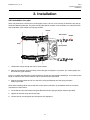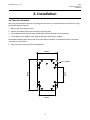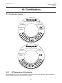
1
Operating Instructions
HALO
MAN0906_Issue 3_11/13
HALO
Operating Instructions
2308M5001
1. Safety Warnings and Information
1 Safety Warnings and Information
WARNINGS
1.
Installation must be in accordance with the recognized standards of the appropriate authority in
the country concerned. For Europe see EN 60079-14 and EN 60079-29-2.
2.
Do not open the enclosure when energised or when an explosive atmosphere may be present.
(The blanking cap / magnet may be removed)
3.
Operators should be fully aware of the action to be taken if the gas concentration exceeds the
alarm level.
4.
Do not modify or alter the construction of the product as essential safety and certification
requirements may be invalidated.
5.
Assessed under ATEX only for ignition hazards.
6.
Access to the interior of the product, when carrying out any work, must be conducted only by
trained personnel.
7.
The terminals under the blanking cap / magnet are IS protected. Refer to the entity parameters.
Only connect appropriately certified ATEX / IECEx apparatus. Apparatus must not be permanently
connected to the IS terminals.
8. Do not use the HALO light ring status indication for safety-related purposes.
9.
Do not leave off the blanking cap / magnet.
10. In order to maintain electrical safety, the unit must not be operated in atmospheres of more than 21% oxygen.
Special Conditions for Safe Use – Terminals
In order to comply with the ATEX Certification, the following special conditions of use must be adhered
to: 1.
Not more than one single or multiple strand lead shall be connected into either side of any terminal,
unless multiple conductors have been joined in a suitable manner, e.g. two conductors into a single
insulated crimped boot lace ferrule.
2.
Leads connected to the terminals shall be insulated for the appropriate voltage and this insulation
shall extend to within 1 mm of the terminal throat.
3.
All terminal screws, used and unused, shall be tightened down to between 0.5 N m and 0.7 N m.
4.
The terminals shall only be installed and wired with cable in an ambient temperature of -10 °C
to +80 °C.
1.2Disposal
Dispose of the product in accordance with local regulations. The materials used are: Enclosure Lid Glass filled polyester with stainless steel inserts
Glass filled polyester containing polyurethane encapsulated printed circuit boards
Continuity plate
Zinc plated steel
2
MAN0906_Issue 3_11/13
HALO
Operating Instructions
2308M5001
1. Safety Warnings and Information
1.3Waste Electrical and Electronic Equipment (WEEE) Directive
This symbol indicates that this product and/or parts of the product may not be treated as household or municipal waste. Waste electrical products (end of life) should be recovered/recycled
where suitable specialist WEEE disposal facilities exist. For more information about recycling of
this product, contact your local authority, our agent/distributor or the manufacturer.
1.4Important Information
This manual is for use with the HALO junction box only.
Honeywell Analytics can take no responsibility for installation and/or use of its equipment if not done so in
accordance with the appropriate issue and/or amendment of the Operating Instructions.
The reader of these Operating Instructions should ensure that it is appropriate in all details for the exact
equipment to be installed and/or operated. If in doubt, contact Honeywell Analytics for advice.
The following types of notices are used throughout these Operating Instructions:
WARNING
Identifies a hazardous or unsafe practice which could result in severe injury or death to personnel.
Caution: Identifies a hazardous or unsafe practice which could result in minor injury to personnel, or
product or property damage.
Note: Identifies useful/additional information.
Every effort has been made to ensure the accuracy of this document, however, Honeywell Analytics can
assume no responsibility for any errors or omissions in this document or their consequences.
Honeywell Analytics would greatly appreciate being informed of any errors or omissions that may be found
in the content of this document.
For information not covered in this document, or if there is a requirement to send comments/corrections
about this document, please contact Honeywell Analytics using the contact details given on the back page.
Honeywell Analytics reserve the right to change or revise the information supplied in this document
without notice and without obligation to notify any person or organization of such revision or change.
If information is required that does not appear in this document, contact the local distributor/agent
or Honeywell Analytics.
3
MAN0906_Issue 3_11/13
HALO
Operating Instructions
2308M5001
Contents
Section
Page
1
Safety Warnings and Information2
1.1 Warnings
2
1.2 Disposal
2
1.3
Waste Electrical and Electronic Equipment (WEEE) Directive
3
1.4
Important Information
3
2
Overview
5
2.1
Optional accessories
6
2.1.1
Adaptor Plate Kit (2308B0930)
6
2.1.2
Pipe Mounting Bracket Kit (2308B0923)
6
2.1.3
Sunshade (2308B0934)
6
3
Installation
7
3.1Siting
7
3.2
Mechanical Installation
7
3.2.1
Installation to a flat surface
7
3.2.2
Installation to a pipe
8
3.2.3
Retrofit installation
9
3.2.4
Sunshade Installation
10
3.3
Remote Sensor Installation
11
3.4
Electrical Installation
11
4
Electrical connections12
4.1
Power supply
13
4.1.1 Example Cable Length Calculation
13
4.2
Cabling recommendations
14
4.3
Earth regimes
14
5
Configuration
15
5.1 General
15
5.2
Configuration process
15
6
Operation
17
6.1
Light Ring
17
6.1.1Start-up
17
6.1.2
Normal operation
17
17
6.2HART® Interface (Optional)
6.3
Alternative communications
18
7
Maintenance
19
7.1 General
19
7.2
Lid Replacement
19
7.3
Enclosure Gasket Replacement
19
8
Problem solving
21
9
Specifications
22
10 Certification
23
10.1 Certification Label
23
10.2 EC Declaration of Conformity
23
11 Ordering Information24
12 Appendix
25
12.1 Wiring Diagram - HALO with Searchpoint Optima Plus
25
12.2 Recommended Tool Kit
26
12.3 Recommended Torque Settings
26
4
MAN0906_Issue 3_11/13
HALO
Operating Instructions
2308M5001
2. Overview
HALO is an ATEX certified Ex e junction box for use with sensors that feature a 4-20 mA output. It provides
a local visual status indication, and an optional intrinsically safe non-intrusive HART® interface for sensors
that support HART® communication. HALO is ATEX approved for use in either Zone 1 (gas) or Zone 21
(dust) hazardous areas.
HALO has three M20 cable entries and one M25 sensor entry. It is supplied with two M20 Ex e certified
blanking plugs. Transport plugs are fitted to the M25 and one of the M20 entries, which must be replaced
with a sensor, suitable cable glands or blanking plugs before use.
Internally, the box has a continuity plate with two earth connection points, and a 12-way terminal block.
Two locking rings are provided (one M20, one M25) to connect to the continuity plate.
The box lid features a three-colour light ring (green, yellow and red), and optional connections for a HART®
handheld device. In operation, the light ring provides a status indication as follows:
• Green – Normal operation or Warning
• Yellow – Fault or Inhibit
• Red – Alarm (level is configurable)
WARNING
Do not use the light ring status indication for safety-related purposes.
The box is configured using a magnetic switch. A magnet is incorporated into the blanking cap which
screws into the middle of the box lid when not in use. The following parameters can be configured:
• Threshold for local alarm indication (red lights)
• Brightness of green lights
M20 entries
HART® connection
(optional)
Earth points
M5 stud with
8 mm A/F nut
Light ring
Blanking cap /
Magnet
Enclosure
M25 entry
Lid
Continuity plate
Lanyard
Magnetic switch
5
MAN0906_Issue 3_11/13
HALO
Operating Instructions
2308M5001
2. Overview
2.1Optional accessories
2.1.1 Adaptor Plate Kit (2308B0930)
For retrofit applications, the optional adaptor plate kit enables HALO
to be mounted in place of an existing DVC100 or Honeywell Analytics
Junction Box. The plate has mounting holes corresponding to the
hole centres of the DVC100 series and the Honeywell Analytics
Junction Box.
The plate has mounting points for the sunshade. The plate is
stainless steel 316. Fixings for the HALO are supplied. Wall mounting
fixings are not supplied.
2.1.2 Pipe Mounting Bracket Kit (2308B0923)
HALO may be fixed to a horizontal or vertical pipe
of 50 to 150 mm (2 to 6 inches) in diameter using
the optional Pipe Mounting Bracket.
The pipe mounting bracket kit consists of two
brackets, two clamps and fixings for the HALO.
The brackets are stainless steel 316.
2.1.3 Sunshade (2308B0934)
An optional sunshade is available which covers
the HALO and can extend over either side to also
protect a sensor.
The sunshade slots over the HALO mounting
bolts so no additional fixings are required. The
sunshade is stainless steel 316.
Use the sunshade to reduce the effects of direct
solar heating.
6
MAN0906_Issue 3_11/13
HALO
Operating Instructions
2308M5001
3. Installation
3.1Siting
The placement of gas detectors should be determined following the advice of:
• experts having specialist knowledge of gas dispersion
• experts having knowledge of the process plant system and equipment involved
• safety personnel
• engineering personnel
The agreement reached on the location of detectors should be recorded.
Guidance on the positioning of gas detectors to provide the best detection coverage is contained in IEC/EN
60079-29-2 and other national Codes of Practice. It is recommended that the installation designer consults
these Codes of Practice when determining where detectors are to be located.
3.2Mechanical Installation
HALO has integral mounting points consisting of four mounting holes in the body, suitable for M6 or
M8 bolts.
HALO may be fixed directly to a suitable flat surface, or to a horizontal or vertical pipe, 50 to 150 mm
(2 to 6 inches) in diameter. The Pipe Mounting Bracket Kit (optional) may be used for this purpose.
The Adaptor Plate Kit (optional) may be used to retrofit HALO to the mounting points of an existing DVC100,
DVC100 MkII, or Honeywell Analytics Junction Box.
3.2.1 Installation to a flat surface
HALO may be fixed directly to a suitable flat surface, using the integral mounting points (dimensions shown
below).
Note: When installing HALO ensure that the correct sensor orientation is considered. Refer to the sensor
manufacturer’s instructions.
Ensure that mounting bolts are fully tightened and suitable locking washers are used.
88mm
124mm
182mm
158mm
4 x Ø 8.75mm
130mm
7
50mm
MAN0906_Issue 3_11/13
HALO
Operating Instructions
2308M5001
3. Installation
3.2.2 Installation to a pipe
HALO may be fixed to a horizontal or vertical pipe of 50 to 150 mm (2 to 6 inches) in diameter using the optional Pipe Mounting Bracket. The pipe mounting bracket kit consists of two brackets, two clamps and four
sets of M6 bolts, plain washers and spring washers.
Bracket
Plain washer
M6 Bolt
Clamp
Spring washer
1. Thread each clamp through the slots in each bracket.
2. Take the first bracket, pass the clamp around the pipe and tighten it in position. (For vertical pipes, this
should be the upper bracket)
Note: For smaller pipe diameters it will be helpful to shorten the clamp before installation. Cut off the excess
length as required, and use the retention clip to secure the end of the band.
3. Take the second bracket and fix it to the HALO using the M6 bolts and the spring and plain
washers provided.
Note: When installing HALO ensure that the correct sensor orientation is considered. Refer to the sensor
manufacturer’s instructions.
4. Fix the HALO to the first bracket using the M6 bolts and the spring and plain washers provided. 5. Tighten the second clamp around the pipe.
6. Ensure that all mounting bolts and clamps are fully tightened.
8
MAN0906_Issue 3_11/13
HALO
Operating Instructions
2308M5001
3. Installation
3.2.3 Retrofit installation
HALO may be retrofitted in place of an existing DVC100 series or Honeywell Analytics Junction Box using
the optional Adaptor Plate Kit.
1. Remove the existing junction box.
2. Position the Adaptor Plate over the existing mounting holes.
3. Fix the Adaptor Plate in place using suitable bolts and locking washers (not supplied).
4. Fix the HALO to the Adaptor Plate using the M6 bolts and washers supplied.
Note: When installing HALO ensure that the correct sensor orientation is considered. Refer to the sensor
manufacturer’s instructions.
5. Ensure that all mounting bolts are fully tightened.
130mm
102mm
200mm
10 x Ø 7 Slots
102mm
9
MAN0906_Issue 3_11/13
HALO
Operating Instructions
2308M5001
3. Installation
3.2.4 Sunshade Installation
The sunshade can be installed offset to the right or left of the HALO. The offset can be chosen to protect a
sensor, or to provide the maximum amount of shade during the course of the day.
The sunshade has a M6 threaded earth stud which can be used to connect it to protective earth.
Note: Fit the earth wire to the sunshade prior to installation.
Earthing stud
1. Slightly loosen the upper mounting bolts of the HALO.
2. Slot the sunshade onto the mounting bolts.
Note: Fit the sunshade in front of the HALO, between the HALO and the washers.
HALO
Sunshade
Bolt
Washers
3. Ensure that the mounting bolts are fully re-tightened, using the long ball-end 5 mm hex wrench supplied
with the sunshade.
10
MAN0906_Issue 3_11/13
HALO
Operating Instructions
2308M5001
3. Installation
3.3Remote Sensor Installation
The sensor may be mounted remotely from the HALO. For example, the HALO can be mounted at a convenient position for access to the optional HART® connection.
Refer to individual sensor manuals for sensor specific limits on remote mounting distances.
The remote mounting distance to the sensor must fall within the overall cable length restrictions to ensure
that the minimum required supply voltage is present at the sensor.
For sensors equipped with HART® communications there are no additional cabling considerations.
3.4Electrical Installation
Caution: HALO has internal cabling between the terminals and the lid. Before removing the lid, ensure that the blanking cap / magnet is screwed in place so that the lid is supported on the lanyard.
1. Ensure that the blanking cap / magnet is screwed in place in the centre of the lid. Do not over-tighten.
2. Unscrew the four captive M6 screws and carefully remove the lid. The lid should be supported on
the lanyard with no strain on the internal cables.
3. Fit a suitable approved Ex e cable gland to the required cable entry for the field cable. Use sealing
washers where necessary to maintain the ingress protection rating (IP66/67). Use one of the supplied
locking rings to connect to the earth continuity plate.
4. Fit a sensor to a suitable entry. (Refer to sensor manual for specific information). Use sealing washers
where necessary to maintain the ingress protection rating (IP66/67). Use one of the supplied locking
rings to connect to the earth continuity plate.
5. Fit approved Ex e blanking plugs to all unused cable entries. Use sealing washers where necessary to
maintain the ingress protection rating (IP66/67).
Caution: Ensure that all red transport plugs have been replaced with the correct blanking plugs, sensor or cable glands.
6. Make electrical connections (see Chapter 4).
7. Carefully replace the lid and fully tighten the four captive M6 screws.
Caution: Take care to avoid trapping cables when replacing the lid.
11
MAN0906_Issue 3_11/13
HALO
Operating Instructions
2308M5001
+V
4-20mA
0V
EARTH
+24V
4-20mA
0V
SENSOR
RED +24V
WHITE mA
WHITE mA
BLACK
0V
LID
4. Electrical Connections
To Controller
Terminal Number
Description
1
2
3
4
5
6
7
8
9
10
11
12
Earth
spare
+V supply
+V supply
mA loop
mA loop
-V supply
-V supply
spare
spare
spare
spare
spare
Field Wiring
Sensor Wiring
Lid Wiring
+24 V
+24 V (red)
mA output
mA (white)
mA (white)
0 V (black)
+24 V
mA output
0V
0V
Earth (if applicable)
Caution: Do not remove factory fitted links
Note: HALO is reverse polarity protected.
Spare conductors must be terminated in a spare terminal. Wiring must be in accordance with local, national
and/or company regulations. Bare conductors must be avoided.
Refer to individual sensor manuals for sensor wiring details. Specific wiring diagrams for some commonly
used sensors are provided in the Appendix.
The mA loop voltage must not exceed 30 Vdc.
12
MAN0906_Issue 3_11/13
HALO
Operating Instructions
2308M5001
4. Electrical Connections
4.1Power supply
HALO requires a voltage supply of 18 - 32 Vdc (nominal 24 Vdc). Power consumption is 1 W maximum.
Refer to individual sensor manuals for sensor specific limits and power consumption.
Ensure that the minimum required supply voltage is present at the sensor, taking into account the voltage
drop due to cable resistance.
Note: Make allowance for the insertion loss resistance.
The maximum loop resistance in the field cable is calculated as follows:
R loop = (V controller – V detector min) / I detector
4.1.1 Example Cable Length Calculation
Example – HALO with Searchpoint Optima Plus:
Searchpoint Optima Plus requires a voltage supply of 18 – 32 Vdc. Its power consumption is 5 W. Therefore
total power consumption including HALO is 6 W maximum.
The controller is supplying a nominal 24 Vdc (V controller) and the detector minimum allowable voltage is
18 Vdc (V detector min), therefore the maximum allowable voltage drop between the controller and detector is
6 Vdc; this means a voltage drop of 3 V in each core (+ve core and -ve core).
Power consumption of the detector is 6 W. The current required to drive the detector at the minimum voltage is (I = P / V), 6 / 18 = 333 mA (I detector).
So, the maximum field cable loop resistance (R loop) = 6 / 0.333 = 18 Ω, or 9 Ω per core.
The following tables show the maximum cable distances between the controller and HALO with Searchpoint
Optima Plus for different cable options, assuming a voltage drop of 3 V in each core. The tables are examples only and actual cable parameters and source power supply voltage for the application should be used
to calculate the maximum cable distance allowed at the installation site.
Maximum cable length for the example calculation above
Typical cable data
Cable size
(cross sectional area)
0.5 mm2 (20 AWG*)
1.0 mm2 (17 AWG*)
1.5 mm2 (16 AWG*)
2.0 mm2 (14 AWG*)
2.5 mm2 (13 AWG*)
*nearest equivalent
Maximum cable length (L)
Cable resistance
Ω/km (Ω/mile)
36.8 (59.2)
19.5 (31.4)
12.7 (20.4)
10.1 (16.3)
8.0 (12.9)
Note: Sufficient operational margins should be allowed
13
Metres
Feet
245
462
709
891
1125
808
1516
2326
2923
3691
MAN0906_Issue 3_11/13
HALO
Operating Instructions
2308M5001
4. Electrical Connections
4.2Cabling recommendations
The cable used must be appropriate for the hazardous area classification and meet local, national and/or
company regulations. The use of industrial grade, screened field cable is recommended.
For example, three-core copper cable with screen (minimum 90% coverage) and suitable mechanical protection (e.g. steel wire armour) to suit M20 gland entry.
The conductor size for the terminals is 0.5 - 4 mm2 (20 - 11 AWG).
Ensure the cable gland is installed correctly and fully tightened. All unused cable/conduit entries must be
sealed with a suitable certified blanking plug.
4.3Earth regimes
Caution: Any earthing regime employed must avoid earth loops.
The following information is provided to assist with proper earthing of HALO:
• HALO has a continuity plate which is in contact with the internal earth points provided (see Electrical
Connections). This is to facilitate connection of the sensor to protective earth.
• Locking rings are supplied which can be used to connect a sensor body or cable gland to the continuity
plate where necessary.
• Field cable screens should be connected to instrument earth at the control room. The other end of
the field cable screen may be terminated in a spare terminal of HALO. It should not be connected to
the continuity plate.
14
MAN0906_Issue 3_11/13
HALO
Operating Instructions
2308M5001
5. Configuration
5.1 General
HALO has two configurable parameters, which are set using the magnetic switch. These are the threshold
for local alarm indication and the brightness of the green lights.
1. Threshold for local alarm indication
The gas reading at which HALO indicates an alarm (flashing red lights) can be set between 10 and
65 %FSD, adjustable in 5 %FSD increments. The default setting is 20 %FSD.
Note: This setting is local to HALO and applies only to the red lights in the box lid. Changing the level will
have no effect on alarm levels configured in the sensor, or in the control room.
2. Brightness of green lights
The green lights indicating normal operation can be set to Full Brightness, Half Brightness or Off.
The default setting is Full Brightness.
WARNING
Do not use the light ring status indication for safety-related purposes.
5.2Configuration process
Note: Configuration mode is indicated by a short yellow flash approximately once per second. HALO will exit
configuration mode after 60 seconds of inactivity and will retain its previous settings, i.e. changed settings
will be discarded.
Note: To activate the magnetic switch, the blanking cap / magnet must be held in place for the required time
and then removed. The switch is only activated as the magnet is removed.
1. Unscrew the blanking cap / magnet from its position in the centre of the lid.
2. Hold the blanking cap / magnet over the (
) marking (magnetic switch) for 3 seconds and remove.
HALO enters configuration mode, indicated by a short yellow flash. A number of red lights are lit
corresponding to the alarm level.
A steady red light means 10 %FSD, a flashing red light means 5 %FSD. For example, two steady lights and
one flashing light indicate 25 %FSD.
15
MAN0906_Issue 3_11/13
HALO
Operating Instructions
2308M5001
5. Configuration
Magnetic switch
3. Hold the blanking cap / magnet over the ( ) marking (magnetic switch) for 1 second and remove to
increase the alarm level by 5 %FSD. Repeat until the required alarm level is reached. (After 65 %FSD
the level will cycle back to 10 %FSD).
4. Hold the blanking cap / magnet over the ( ) marking (magnetic switch) for 3 seconds and remove
to save.
HALO is now in the green lights configuration mode indicated by a short yellow flash. The green lights may
be on or off.
5. Hold the blanking cap / magnet over the ( ) marking (magnetic switch) for 1 second and remove to
change the brightness of the green lights. Repeat until the required setting is reached. (The lights will
cycle through Full Brightness, Half Brightness and Off).
6. Hold the blanking cap / magnet over the ( ) marking (magnetic switch) for 3 seconds and remove to
save and exit configuration.
HALO returns to normal operation. The lights correspond to the current status of the sensor output.
Note: If the yellow lights are still flashing indicating configuration mode, then the save operation has not
been done. Repeat step 6.
Note: If the new settings are not saved, HALO will exit configuration after 60 seconds, and will retain its
previous settings.
7. Replace the blanking cap / magnet . Ensure that the o-ring is in place and screw it into position in the
centre of the lid. Do not over-tighten.
16
MAN0906_Issue 3_11/13
HALO
Operating Instructions
2308M5001
6. Operation
6.1Light Ring
6.1.1 Start-up
HALO’s start-up sequence takes approximately 10 seconds. During this time the lights will flash in rotation.
After the start-up period the lights will indicate the sensor output status.
Note: Depending on the duration of the sensor start up routine, the sensor may still be initialising. Therefore
HALO may indicate Fault or Inhibit for a short time before indicating Normal status.
6.1.2 Normal operation
During normal operation, the light ring provides an indication of the sensor status based on the sensor
4-20 mA output as follows:
Sensor Output
Light Ring
Typical Status
Less than 1.5 mA
Flashing Yellow
Fault
1.5 to less than 2.5 mA
Steady Yellow
Inhibit
2.5 to less than 3.5 mA
Flashing Green
Warning
3.5 mA to less than Alarm Threshold*
Steady Green**
Normal
Greater than or equal to Alarm Threshold* Flashing Red
Hazardous Gas Concentration
* Configurable between 10 and 65 %FSD (5.6 mA to 14.4 mA)
** Configurable to Full Brightness, Half Brightness or Off
Note: the tolerance on the switching thresholds is ±0.3 mA
Configuration mode is indicated by flashing yellow that is slower (1 Hz) and shorter than Fault status (2 Hz).
For details of configuration see Chapter 5.
Note: The visual output of HALO is dependent on the sensor 4-20 mA output only. Use the HART® or RS485
communications to the sensor (where supported) to gain further diagnostic information.
6.2Intrinsically Safe (IS) HART® Interface (Optional)
HALO features an optional intrinsically safe HART® interface that allows local, non-intrusive connection of a
HART® handheld device to a sensor that supports HART® communication.
The HART® connection is accessed by unscrewing the blanking cap / magnet in the centre of the lid.
Refer to the individual sensor manual for HART® communication information.
Note: The HART® communication is directly with the sensor, not with HALO.
Note: HALO is compatible with the HART® Point-to-Point mode of operation only.
17
MAN0906_Issue 3_11/13
HALO
Operating Instructions
2308M5001
6. Operation
6.3Alternative communications
If the sensor features an RS485 interface (i.e. Honeywell Analytics optical products) this can be accessed
using the Honeywell Analytics SHC1 Handheld Interrogator and the SHC Protection Device, by direct
connection to the terminals inside the HALO.
Caution: Do not connect the SHC1 Handheld Interrogator and/or the SHC Protection Device to the
intrinsically safe HART® terminals on the HALO lid.
Note: A hot work permit may be required for this procedure.
Refer to the individual sensor manual for details of how to use the SHC1 Handheld Interrogator.
18
MAN0906_Issue 3_11/13
HALO
Operating Instructions
2308M5001
7. Maintenance
7.1 General
Periodically inspect HALO and cabling for signs of physical damage. Clean the light ring with a damp cloth.
Do not use solvents or abrasive cleaners.
HALO has no user serviceable parts. Honeywell Analytics recommend that the unit’s configuration and
operation are checked annually.
The gas detectors connected to HALO should be checked and if necessary zero and span calibrated by
following the procedures detailed in their operating instructions.
Note: A Service Spares Kit is available (part number 2308B0969) containing an enclosure gasket, an o-ring
for the blanking cap / magnet and a set of replacement lid screws.
7.2 Lid Replacement
The lid assembly can be replaced, for example in the event of failure of the light ring.
1. Unscrew the four captive M6 screws and carefully remove the lid. The lid should be supported on the
lanyard with no strain on the internal cables.
2. Disconnect the lid wires from the terminal block (one red, one black and two white wires)
Caution: Do not remove factory fitted links.
3. It is recommended to make a note of the original serial number of HALO and mark the serial number
inside the enclosure. Retain a record of the original serial number in the maintenance record for the
installation (refer to IEC/EN 60079-29-2).
4. Unscrew the blanking cap / magnet from the centre of the lid.
5. Screw the blanking cap / magnet in place in the centre of the replacement lid. Do not over-tighten.
6. Connect the replacement lid wires to the terminal block in accordance with Chapter 4 Electrical
Connections.
7. Carefully replace the lid and fully tighten the four captive M6 screws.
Caution: Take care to avoid trapping cables when replacing the lid.
Note: The replacement lid will have default settings for the threshold for local alarm indication and the
brightness of the green lights. It may be necessary to re-program the configuration.
7.3 Enclosure Gasket Replacement
The main enclosure gasket can be replaced if it has become damaged. A replacement gasket is contained
in the Service Spares Kit (part number 2308B0969).
Caution: HALO has internal cabling between the terminals and the lid. Before removing the lid,
ensure that the blanking cap / magnet is screwed in place so that the lid is supported on the lanyard.
1. Ensure that the blanking cap / magnet is screwed in place in the centre of the lid. Do not over-tighten.
2. Unscrew the four captive M6 screws and carefully remove the lid. The lid should be supported on the
lanyard with no strain on the internal cables.
19
MAN0906_Issue 3_11/13
HALO
Operating Instructions
2308M5001
7. Maintenance
3. Remove the gasket, ensuring that lid surfaces are not damaged in the process.
4. Unscrew the blanking cap / magnet. Support the lid to avoid putting strain on the internal cabling
between the terminals and the lid.
5. Pass the replacement gasket over the lid, taking care not to stretch it.
6. Screw the blanking cap/ magnet back in place in the centre of the lid. Do not over-tighten.
7. Starting at one corner, gently push the replacement gasket into the groove. Work round the groove until
the gasket is fully fitted. Take care not to stretch or twist the gasket.
8. Carefully replace the lid and fully tighten the four captive M6 screws.
Caution: Take care to avoid trapping cables when replacing the lid.
20
MAN0906_Issue 3_11/13
HALO
Operating Instructions
2308M5001
8. Problem solving
Fault / Problem
Remedial Action
Lights do not work
1. Check if the green brightness is configured to “Off” (see Configuration)
2. Check the lid wiring connections
3. Check that the wires have not been trapped in the lid and damaged
4. If necessary, replace the lid assembly
An individual light does not work
1. An LED has failed, replace the lid assembly.
Incorrect / unexpected light operation
1. HALO may have been wrongly connected. Check all connections.
2. If connections were wrong, power off the unit, wait 1 minute, then apply
power again.
Lights are not bright enough
1. Check the light ring for build-up of contamination and clean with a damp
cloth if necessary
2. Check the configuration – if the green brightness is set to “Half Brightness”
it can be changed to “Full Brightness” (see Configuration)
No HART® communications
Note: HART® communications is directly with the sensor, not with
HALO
1. Check that sensor supports HART® communications
2. Check that the HART® handheld device is connected properly
3. Check that the HART® handheld device has the correct Device Description
files for the sensor (refer to sensor manual)
Cannot configure the unit
1. Ensure that the blanking cap / magnet is being held in the correct position
over the ( ) marking (magnetic switch)
2. Ensure that the magnet is being held in place and then removed to activate
the switch
3. Ensure that the blanking cap / magnet is being held in place for 3 seconds
and then removed to enter configuration mode. Configuration mode is
indicated by a short yellow flash
4. Try an alternative blanking cap / magnet
After configuration the unit does not have the
correct settings
1. After configuration, hold the blanking cap / magnet over the magnetic
switch for 3 seconds and remove to save the new settings. If this is not done,
HALO will exit configuration mode after a time out, and will retain its previous
settings
21
MAN0906_Issue 3_11/13
HALO
Operating Instructions
2308M5001
9. Specifications
Operating and storage temperature
-40 °C to 65 °C
Operating and storage pressure
80 to 120 kPa
Operating and storage humidity
0 to 99 %RH (non-condensing)
Supply voltage
18 to 32 Vdc
Power consumption
1 W maximum
Ingress Protection
IP66/67
Weight
1.7 kg
Material
Glass filled polyester, static dissipative
IS Entity Parameters (optional HART interface
connection only)
®
Output Parameters
Input Parameters
Uo = 8 V
Io = 135 mA
Po = 270 mW
Co = 4 µF
Lo = 1 mH
Ui = 15 V
Ii = 20 mA
Pi = 20 mW
Ci = 0
Li = 20 µH
mA Loop voltage
30 Vdc maximum
mA Loop current
30 mA maximum
mA Loop insertion loss
25 Ω maximum
Dielectric Strength
HALO conforms with the dielectric strength requirement of EN 60079-11
EMC
EN 50270, EN 60945
RoHS
HALO is RoHS compliant
22
AND MUST ONLY BE UPDATED BY C.A.D.
MAN0906_Issue 3_11/13
HALO
Operating Instructions
2308M5001
10. Certification
10.1 Certification Labels
HALO JUNCTION BOX - HART
Part No:
2308B09XX
R
Serial No:
Z123456789012
Vmax:32 V dc
Pmax:1 W
IP66/67
0518
Entity Parameters
See Manual
LABEL ARTWORK
HALO
HALO JUNCTION BOX
Part No:
2308B09XX
LABEL
Serial No:
Z123456789012
Vmax:32 V dc
Pmax:1 W
IP66/67
Ø67 REF
0518
TAINLESS STEEL, MIN THICKNESS 0.3 ATTACHED
DHESIVE.
ARTWORK TO BE INDELIBLY MARKED BY LASER
T MARKING,
OR PRINTING.
10.2 ETCHING
EC Declaration
of Conformity
ER TO BE UNIQUE NUMBER CONTAINING YEAR
EC declaration of conformity is available on the CD accompanying the product. This document lists
TURE. AthefullEuropean
Standards with which the HALO complies.
NSIONS
INGS AND ADDITIONAL CERTIFICATION APPROVALS
D IN ADDITION TO MARKINGS SHOWN.
23
MAN0906_Issue 3_11/13
HALO
Operating Instructions
2308M5001
11. Ordering Information
Part Number
Description
2308B0903
HALO junction box ATEX/IECEx
2308B0941
HALO junction box Inmetro*
2308B0947
HALO junction box GOST*
2308B0953
HALO junction box CCCF*
2308B0900
HALO junction box with HART® connection ATEX/IECEx
2308B0940
HALO junction box with HART® connection Inmetro*
2308B0946
HALO junction box with HART® connection GOST*
2308B0952
HALO junction box with HART® connection CCCF*
2308B0970
Lid assembly – HALO ATEX/IECEx
2308B0971
Lid assembly – HALO Inmetro*
2308B0972
Lid assembly – HALO GOST*
2308B0973
Lid assembly – HALO CCCF*
2308B0974
Lid assembly – HALO with HART® connection ATEX/IECEx
2308B0975
Lid assembly – HALO with HART® connection Inmetro*
2308B0976
Lid assembly – HALO with HART® connection GOST*
2308B0977
Lid assembly – HALO with HART® connection CCCF*
2308B0978
Blanking cap / magnet assembly including lanyard
2308B0924
Terminal block spares assembly
2308B0934
HALO Sunshade
2308B0930
Adaptor Plate Kit
2308B0923
Pipe Mounting Bracket Kit
2308B0969
Service Spares Kit
* Contact Honeywell Analytics for availability
Additional copies of this manual, in English and various other languages, may be downloaded from our
website. Navigate to www.honeywellanalytics.com and select Technical Services & Support, then Technical
Library.
24
MAN0906_Issue 3_11/13
HALO
Operating Instructions
2308M5001
12. Appendix
12.1 Wiring Diagram - HALO with Searchpoint Optima Plus
25
MAN0906_Issue 3_11/13
HALO
Operating Instructions
2308M5001
12. Appendix
12.2 Recommended Tool Kit
Tool
Operation
5 mm A/F Hexagon Key
M6 Lid Screw Removal & Replacement
3 mm Flat Blade Screwdriver
Terminal Block Wiring / Blanking Cap / Magnet
Removal & Replacement
8 mm A/F Socket
M5 Earth Terminal Nut Removal & Replacement
10 mm A/F Hexagon Key
Ex e Blanking Plug Removal & Replacement
No.2 Pozidriv Screwdriver
Lanyard Removal & Replacement
No.1 Pozidriv Screwdriver
Terminal Block Removal & Replacement
Adjustable Pliers / Hammer & Punch
Locking Ring Removal & Replacement
12.3 Recommended Torque Settings
Fixings
Torque Setting
Terminal Screws
0.5 – 0.7 N m
Lid Screws
4Nm
26
Find out more
www.honeywellanalytics.com
Contact Honeywell Analytics:
Europe, Middle East, Africa, India
Life Safety Distribution AG
Javastrasse 2
8604 Hegnau
Switzerland
Tel: +41 (0)44 943 4300
Fax: +41 (0)44 943 4398
India Tel: +91 124 4752700
[email protected]
Americas
Honeywell Analytics Inc.
405 Barclay Blvd.
Lincolnshire, IL 60069
USA
Tel: +1 847 955 8200
Toll free: +1 800 538 0363
Fax: +1 847 955 8210
[email protected]
Technical Services
EMEAI: [email protected]
US:
[email protected]
AP:
[email protected]
www.honeywell.com
Please Note:
While every effort has been made to ensure accuracy in this publication,
no responsibility can be accepted for errors or omissions. Data may change,
as well as legislation and you are strongly advised to obtain copies of the most
recently issued regulations, standards and guidelines. This publication is not
intended to form the basis of a contract.
Issue 3_11/2013
H_MAN0906_EMEAI
2308M5001_ECO A04175
© 2013 Honeywell Analytics
12835
Asia Pacific
Honeywell Analytics Asia Pacific
#701 Kolon Science Valley (1)
43 Digital-Ro 34-Gil, Guro-Gu
Seoul 152-729
Korea
Tel: +82 (0)2 6909 0300
Fax: +82 (0)2 2025 0328
[email protected]