1
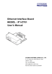
Ethernet Interface Board MODEL : IF2-ET01 User’s Manual Ver.1.00 CITIZEN SYSTEMS JAPAN CO., LTD. 6-1-12, Tanashi-cho, Nishi-Tokyo-shi, Tokyo, 188-8511, Japan TEL: +81-424-68-4608 [email protected] http://www.citizen-systems.co.jp/english/ Contents Contents ......................................................................................................................... 2 Read before using ......................................................................................................... 3 Safety Instructions ........................................................................................................ 4 1. Introduction ............................................................................................................. 9 1-1. Specifications ......................................................................................................................... 9 1-2. Part Names and Functions ................................................................................................. 10 1-3. LED Functions..................................................................................................................... 11 1-4. Using the Panel Button ...................................................................................................... 12 1-4-1. 1-4-2. 1-5. Printing the Ethernet Interface Board Configuration ..................................................... 12 Returning the Ethernet Interface Board Configuration to Factory Default Settings ... 13 Print Server ......................................................................................................................... 14 1-5-1. 1-5-2. Accessing Print Server Configuration screen ................................................................... 14 Checking or Changing Ethernet Interface Board Configuration .................................... 15 2. Network Settings ................................................................................................... 17 2-1. Using the Print Servers Configuration Screen ................................................................. 17 2-1-1. Setting the IP Address ....................................................................................................... 17 2-1-3. Checking the Ethernet Interface Board Version Information ......................................... 18 2-1-2. 2-2. Checking the Operational Status of Printer..................................................................... 17 Network Seeker ................................................................................................................... 19 2-2-1. 2-2-2. Starting Network Seeker ................................................................................................... 19 Changing Settings .............................................................................................................. 21 3. Installing Ethernet Interface board and LAN cable ............................................ 22 2 Read before using Be sure to read this manual carefully before using the product. After you read it, store it in a safe place so that you can reread it when necessary. Contents of this manual may be changed without notice. Reproducing and/or copying the contents of this manual by any means without permission are prohibited. We will not be responsible for any adverse occurrence that results from the use of this manual, regardless if it contains omissions, errors/misprints, etc. Note that we will not be responsible for (a) loss caused by improper operation or mishandling of the device by the user, or (b) loss due to operational environment. Data etc., are basically impermanent; long time or permanent storing/saving of data by the device is not possible. Note that we will not be responsible for any loss or loss of profits owing to loss of data due to breakdown, repairs, inspections, etc. Please contact us if there are omissions, errors, ambiguities, etc. in this manual. Refer to this document along with the user manual of the printer. This product operates by setting up a wireless connection between itself and other wireless LAN equipment for data transmission. Therefore, other wireless LAN equipment is required to use this product. While we have confirmed the operation of this product with certain wireless LAN equipment, operation with all types of wireless LAN equipment is not guaranteed. Carry out a sufficient evaluation before using this product. Trademarks ・ Microsoft, Windows XP, Windows Vista, Windows 7 and Windows 8 are registered trademarks of Microsoft Corporation U.S.A. ・ Other company names and product names mentioned here are trademarks or registered trademarks of those companies. 3 Safety Instructions Before handling the product (removing from packaging, etc.), discharge static electricity by touching metal, etc. Do not spill liquid onto the device. Do not place the device in a humid place. Do not step on, or subject the network cable connected to the device to rough treatment. Do not connect a telephone line to the RJ45 connector on the device. Be sure to connect STP cable (category 5 or higher). Connect the product only to devices that operate on SELV voltage (safety extra-low voltage). Be sure to use the device inserted in the interface board slot of the printer. Do not use the device when it is not inserted in the interface board slot. 4 Safety Instructions Declaration of Conformity The printers using this WLAN interface board conform to the following Standards: The Low Voltage Directive 2006/95/EC, the EMC Directive 2004/108/EC, the RoHS Directive 2002/95/EC, and the WEEE Directive 2002/96/EC. LVD : EN60950-1 EMC: EN55022 Class A EN61000-3-2 EN61000-3-3 EN55024 This declaration applies only to the 230-V model. IMPORTANT: This equipment generates, uses, and can radiate radio frequency energy and if not installed and used in accordance with the instruction manual, may cause interference to radio communications. It has been tested and found to comply with the limits for a Class A computing device pursuant to Subpart J of Part 15 of FCC Rules, which are designed to provide reasonable protection against such interference when operated in a commercial environment. Operation of this equipment in a residential area is likely to cause interference, in which case the user at his own expense will be required to take whatever measures may be necessary to correct the interference. CAUTION: Use shielded cable for this equipment. 5 Safety Instructions Sicherheitshinweis Die Steckdose zum Anschluß dieses Druckers muß nahe dem Gerät angebracht und leicht zugänglich sein. For Uses in Canada This Class A digital apparatus complies with Canadian ICES-003. This digital apparatus does not exceed the Class A limits for radio noise emissions from digital apparatus, as set out in the radio interference regulations of the Canadian department of communications. Pour L’utilisateurs Canadiens Cet appareil numérique de la Classe A est conforme à la norme NMB-003 du Canada. Cet appareil numérique ne dépasse pas les limites de carégorie a pour les émissions de bruit radio émanant d’appareils numériques, tel que prévu dans les réglements sur l’interférence radio du départment Canadien des communications. 6 Safety Instructions GENERAL PRECAUTIONS Before using this product, be sure to read through this manual. After having read this manual, keep it in a safe, readily accessible place for future reference. The information contained herein is subject to change without prior notice. Reproduction or transfer of part or all of this document in any means is prohibited without permission from Citizen Systems. Note that Citizen Systems is not responsible for any operation results regardless of omissions, errors, or misprints in this manual. Note that Citizen Systems is not responsible for any trouble caused as a result of using options or consumables that are not specified in this manual. Except explained elsewhere in this manual, do not attempt to service, disassemble, or repair this product. Note that Citizen Systems is not responsible for any damage attributable to incorrect operation/handling or improper operating environments that are not specified in this manual. Data is basically for temporary use and not stored for an extended period of time or permanently. Please note that Citizen Systems is not responsible for damage or lost profit resulting from the loss of data caused by accidents, repairs, tests or other occurrences. If you find omissions, errors, or have questions, please contact your Citizen Systems dealer. If you find any pages missing or out of order, contact your Citizen Systems dealer for a replacement. 7 Safety Instructions Important FCC Radiation Exposure Statement The radiation exposure from this equipment is within the FCC RF radiation exposure limits for an uncontrolled environment. It is recommended that you install and operate this equipment with a minimum of 20 cm between the radiator and your body. CE Mark Warning This equipment is classified as a Class B product and may cause radio interference in a home environment. In such cases, the user is requested to take the necessary countermeasures to resolve the interference. Restrictions by Country Frequency range: 2400.0 to 2483.5 MHz Country Bulgaria Restrictions None France Outdoor use is limited to 10 mW e.i.r.p. within the band 2,454 to 2,483.5 MHz Italy None Luxembourg None Norway Implemented Russian Federation None Note: Do not use this equipment outdoors in France. 8 Notes Outdoor use and public service require general authorization. Used for military radiolocation. The 2.4 GHz band is being reformed to relax the current regulations. Full implementation is planned by 2012. Outdoor use requires general authorization. Network and service supply (not for spectrum) require general authorization. The geographical area within a radius of 20 km from the center of Ny-Ålesund is excluded from this subsection. For indoor use only. 1. Introduction Thank you for purchasing the Citizen IF2-ET01 Ethernet interface board. IF2-ET01 Ethernet Interface Board is compatible with the Line Thermal Printer CT-S251 series. Connecting the IF2-ET01 to a printer enables you to relay data between a network of multiple computers and the printer. In addition, the computers and printer are able to communicate with each other: the operational status, print settings, and other information about the printer can be checked from computers on the network. 1-1. Specifications Compatible printers CT-S251 Series Operation panel LED: 2 (RJ45 connector) Button: 1 (on panel) Network Interface Auto-Negotiation (100Base-TX/10-Base-T) AUTO-MDIX (Straight/Cross cable auto detection) Connection to the printer SPI IP Version IPv4 Network protocols TCP, UDP, HTTP, SNMP, ICMP, DHCP Port number for printing TCP 9100 (Default) Configuration changes Yes from the browser Interactive communication Yes (only when CITIZEN TCP/IP port driver is used) External dimensions 80 mm (W) x 70 mm (D) x 25 mm (H) (including connector protuberance) Weight Approx. 75 g Operating environment 0 to 40°C, 10 to 90% RH (condensation free) Storage environment -20 to 90°C, 10 to 91% RH (condensation free) Safety standards VCCI Class B 9 Introduction 1-2. Part Names and Functions Ethernet interface board unit ① ② ③ ④ ⑤ ① USB connector Works as standard USB connector ② RJ45 connector (compatible with 10Base-T/100Base-TX) Connection for LAN cable. ③ Green LED Shows network transmission speed with steady/blinking light. ④ Yellow LED Shows network connection status (disconnected, receiving data, etc.) ⑤ Panel button Used to operate the IF2-ET01. 10 Introduction 1-3. LED Functions The following charts show what each LED indicator indicates. ① ② ① Network transmission speed Transmission speed LED (green) 100 Mbps On 10 Mbps / disconnected Off ② Link status with network Link status LED (yellow) Connected On Disconnected Off Transmitting data Flashing 11 Introduction 1-4. Using the Panel Button The panel button on the operation panel is used to operate the IF2-ET01. You can use it to print settings information and restore factory default settings. Panel button 1-4-1. Printing the Ethernet Interface Board Configuration Press the panel button to print out the IF2-ET01 configuration. ① I/F Board Information ② Firm Ver. ③ Current Status IP Addr. : 192.168.11.4 Subnet : 255.255.255.0 Gateway : 192.168.11.1 ④ User Configuration Host Name : no name MAC : 00:01:02:0a:0b:0c IP Addr. : 169.254.1.10 Subnet : 255.255.0.0 Gateway : 0.0.0.0 DHCP : ON PrintPort : 9100 Timeout : 60 ■ Configuration items that are printed ① Title of the printout. ② Firmware version of printer.. ③ Network settings such as the IP address currently being used. When the network is not connected, the IP address is “0.0.0.0”. ④ Same data as configuration settings on the Print Server Configuration screen. *** If panel button is pressed within 60 seconds after power on with DHCP enabled settings, IP address may not be obtained yet. In such case, IP address is shown as 0.0.0.0. 12 : EM00-0000X Introduction 1-4-2. Returning the Ethernet Interface Board Configuration to Factory Default Settings 1) Press and hold the panel button. 2) When you hear the beep, press and hold the panel button again within 3 seconds. The following message is printed, and the IF2-ET01 returns to factory default settings. I/F Board Information ] --!Caution!-Printer will automatically restart. Warning When the operation is complete, the IF2-ET01 restarts automatically. When the IF2-ET01 is set to automatically obtain the IP address from the DHCP server, the IP address assigned may be different from the previous one. 13 Introduction 1-5. Print Server Using a Web browser, you can go to the Print Server Configuration screen to view or change the network settings. 1-5-1. Accessing Print Server Configuration screen 1) Launch your browser and go to the URL of the Print Server Configuration screen. For the URL, enter the IP address assigned to the printer. (For example, if the IP address is “169.254.1.10”, enter “http://169.254.1.10”.) 2) Print Server Configuration page to show current settings appears. 3) By clicking “Edit” button, screen move to the page to change the settings. 14 Introduction 1-5-2. Changing the Print Server Configuration By clicking “Edit” button, screen is changed for the page to change the network settings. [Back] button: The page moves back to the page to check the current network settings. [Cancel] button: The entry data on this page is canceled. [Save] button: The entry data on this page is saved and move the page below then the printer reboots after few seconds. Warning When the operation is complete, the IF2-ET01 restarts automatically. When the IF2-ET01 is set to automatically obtain the IP address from the DHCP server, the IP address assigned may be different from the previous one. 15 Introduction ■ List of network setting items Classification Item Network setting Host name Description Name to identifying the printer Changeable Yes “no name” (factory default) Available character for the host name is ASCII code 0x20 to 0x7E and 0 to 31 characters. TCP/IP settings MAC address IP address from DHCP IP address Subnet mask Print settings MAC address Setting to obtain IP address from DHCP server Enable: ON (factory default) Disable: OFF Static IP address 169.254.1.10 (factory default) Subnet mask 255.255.0.0 (factory default) Gateway IP address Gateway IP address 0.0.0.0 (factory default) Print port number Time out duration for print data Print port number used for TCP 9100 (factory default) Time-out duration of connection to host machines (0 to 65535 seconds). “0” means no time-out. 60 (factory default) ・ We recommend setting the time-out duration for at least 30 seconds. 16 No Yes Yes Only when “IP address from DHCP” is “Disable” Only when “IP address from DHCP” is “Disable” Yes Yes 2. Network Settings 2-1. Network settings from the browser 2-1-1. Accessing the Print Server configuration screen The followings are examples of the PC/printer preparation to access the print server. Example 1: Setting the static IP address from browser on directly connected PC Press panel button to check IP address of the printer. Connect the printer and the PC via LAN cable directly. On the TCP/IP setting of the PC, set the IP address of the same network as the printer. You can access the print server function from the browser by entering IP address as URL (If IP address of the printer is 169.254.1.10, IP address of PC should be like 169.254.1.11 and URL on the browser should be http://169.254.1.10) Example 2: Setting static IP address from browser using DHCP server Connect the printer to the network that DHCP server is working. As IP address is supposed to be assigned from DHCP sever, check IP address by pressing panel button after 60 seconds. You can access the print server function from the browser of the PC that is in the same network as the printer by entering printer IP address as URL. (If IP address assigned to the printer is 192.168.1.100, URL is like http://192.168.1.100) 2-1-2. Setting the IP address Network communication is based on the IP addresses assigned to each network devices. IP address setting of this board is either by automatic assignment from DHCP server or by setting static IP address manually. Default setting is automatic assignment by DHCP server. ■ Setting to get IP address from DHCP server automatically 1) Using the Web browser, access the Print Server Configuration screen. (Refer to “1-5. Print Server” for the setting screen access method. 2) In “TCP/IP settings” group, set “IP address from DHCP” to “Enable”. 3) Click “Save” to save the changes. (Printer will reboot with new network settings.) 4) Switch on the printer. After the printer is switched on, the printer automatically obtains the IP address from the DHCP server within 60 seconds. If IP address cannot be obtained in 60 seconds, default IP address (169.254.1.10) will be assigned. (If you check IP address during obtaining IP address, the address will be shown as 0.0.0.0) 17 Network Settings ■ Setting the IP address manually 1) Using the Web browser, access the Print Server Configuration screen. (Refer to “1-5. Print Server” for the setting screen access method. 2) In “TCP/IP settings” group, set “IP address from DHCP” to “Disable” and enter the necessary IP address to the “IP address”. 3) Click “Save” to save the changes. (Printer will reboot with new network settings.) 2-1-3. Changing other settings If necessary, change the other settings than IP address. The way to change setting is same as IP address settings. For the details of changeable setting, refer to List of network setting items in section 1-5-2 “Changing Print Server Configuration” 18 Network Settings 2-2. Network Seeker By using “CITIZEN Network Seeker”, utility software that runs on Windows, you can check and change the Ethernet interface board settings. 2-2-1. Starting Network Seeker After obtaining the program “NetSeeker.exe” from the CD-ROM or our website, double click the program. A dialog box appears. Click “Seek” to start a LAN IF search. ① ② ④ ③ ⑤ ⑧ ⑥ 19 ⑦ Network Settings ① “Seek” button Start a search for Ethernet interface boards on the network. The search function waits for a response for the duration set for ⑦. ② “Edit config” button Change the settings of the selected board. ③ Board information list A list of discovered boards. ④ Board information Single click to select a board and double click to change settings. ⑤ Configuration display section View the settings of the selected board. ⑥ Client condition display When “Busy” is displayed, operations to search, change settings, and so on are prohibited. If you click “Stop”, the “Busy” status is cleared forcibly. ⑦ Communication timeout You can configure the time-out duration for searches and other operations. ⑧ Status log View the status of the utility. 20 Network Settings 2-2-2. Changing Settings You can configure an Ethernet interface board by selecting it at the main dialog box, and then clicking “Edit config”. ① ② ① These are unalterable parameters. These parameters are for display purposes only. ② These are changeable parameters. Users can change these parameters. 21 3. Installing Ethernet Interface board and LAN cable ■ Connecting to the Printer 1) Switch off the power and remove the power cord from the printer. 2) If another interface board is installed in the printer, remove it. 3) Insert the IF2-ET01 into the interface slot of the printer. 4) Fix the IF2-ET01 in place with screws. Warning ・ Malfunctions may occur if the IF2-ET01 is removed or re-inserted. ・ To install the IF2-ET01, please contact your dealer or service person. ・ If you work on your own, consider static electricity and other factors carefully, and then install IF2-ET01 at your own responsibility. ■ Connecting to the Network Connect the LAN cable to the RJ45 connector. 22