1
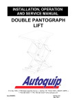
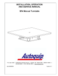
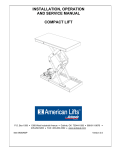
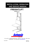
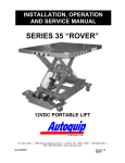
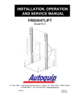
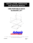
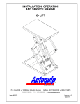
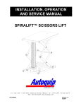
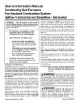
GATE & ENCLOSURE
INSTALLATION MANUAL
SWING GATES
P.O. Box 1058 • 1058 West Industrial Avenue • Guthrie, OK 73044-1058 • 888-811-9876 •
405-282-5200 • FAX: 405-282-3302 • www.autoquip.com
Item # 830SG
Version 2.0
01/2008
TABLE OF CONTENTS
Introduction
3
Inspection and Identification
4
Pre-Installation Site Visit
5
Responsibility of Owners/Users
6
Safety Signal Words
7
Safety Practices
8
Label Placement
10
Gate Installation Instructions
13
Enclosure Installation Instructions
33
Routine Maintenance
36
Replacement Parts List
37
Warranty
38
IMPORTANT
Please read and understand this manual prior to operation. If any questions should
arise, call a local representative or Autoquip Corporation at 1-888-811-9876 or 405-2825200.
PLANNED MAINTENANCE PROGRAM
A local Autoquip representative provides a Planned Maintenance Program (PMP) for
this equipment using factory-trained personnel. Call a local representative or Autoquip
Corporation at 1-888-811-9876 or 405-282-5200 for more information.
2
INTRODUCTION
Autoquip Corporation has designed and manufactured these gates and enclosures to
conform to ANSI Standard B20.1b in order to provide personnel protection from moving
loads on the lift and to ensure safe access to the lift at every operating level. They have
been built to provide many years of dependable service and proper installation of this
equipment is vital to personnel safety. It is vital for the installers to read and
understand this manual! These instructions have been prepared and organized to
assist the installers and it is important for these individuals to carefully follow the steps
in the order they are presented!
Situations may arise which are not covered in these installation instructions. If you have
questions, please call Autoquip Customer Service at (405) 282-5200 or 1-888-8119876.
NOTE: Unless otherwise stated, mechanical installation does not include
unloading, permits, seismic calculations, or extensive acceptance testing. The
requirements of each contract should be carefully reviewed for possible conflicts
of interpretation.
3
INSPECTION & IDENTIFICATION
The following items are typically shipped loose within each manually operated Vertical
Gate order:
A.
B.
C.
D.
E.
Gate with posts, header, and expanded metal panel(s)
Interlock Kits
Misc. Gate Mounting Hardware, Manual, and Signs/Labels
Varies – Expanded Metal Enclosure Panels per General Arrangement Drawing
Varies – Enclosure Panel Mounting Tek-Screws, Top Caps, Corner Angles
NOTE: The “Bill of Lading” will state the number of pieces shipped. TWO ITEMS
MAY BE BANDED TOGETHER AND COUNT AS ONE PIECE.
Upon receipt of the shipment, check for exposed damage or shortages and make note
of it on the trucking company Bill of Lading or the Shipping Papers. Reports of
concealed damage to items contained in crates must be reported within 48 hours. DO
NOT destroy the crating while opening it to inspect the contents. If damage is
suspected or found, report it directly to the carrier. DO NOT contact Autoquip
Corporation!! All shipments are FOB from the Autoquip plant. Any claims for damage
must be filed with the carrier. Any parts shipped from Autoquip that are intended
to replace damaged or lost items will be invoiced to the ordering party.
Assuming no damage has occurred to the crate, check the components against the
packing list. This will provide assurance that every item shipped has been received.
Everything needed for the installation should be available. If not, report any shortages to
Autoquip Corporation within 10 days. (Autoquip is not responsible for parts lost, stolen
or damaged during transportation, storage, installation, or during any other
circumstances or conditions that may be beyond corporate control.)
Before beginning the installation process, look at the skid that the gates and enclosures
arrived on. Check for any damage and compare the packing list to the gates and
enclosures to ensure that everything is on hand. If there are any missing pieces,
contact Autoquip Product Support Team at (405) 282-5200.
4
PRE-INSTALLATION SITE VISIT
SITE CONDITIONS
Whenever possible, make a pre-installation visit or call someone at the site. Installers
must be familiar with everything relative to proper installation of this equipment. Some
concerns are listed below, though listing every affecting contingency is impossible. It is
the installer’s responsibility to check the site for problems and work out solutions with
the appropriate people. Some of the areas of concern are:
1.
Is the site accessible?
2.
Can the equipment get through the existing doorways, halls, and shaft openings?
3.
How will the unit be raised, set into position, and accessed?
4.
Can a chain fall be hooked to an available overhead support?
5.
Is there a forklift available?
6.
Is bracing required?
7.
Look for problem areas such as bracing and overhead interference from ducts,
joists, and pipes.
It is always best to be prepared, so do as much pre-planning as possible before the
installation procedure actually begins. Learn about the site, the equipment, and the
installation process.
5
RESPONSIBILTY OF OWNERS/USERS
CODE COMPLIANCE
Ultimate responsibility for gaining state and local code approval is the responsibility of
the buyer of the VRC. Please acquaint yourself with the permitting and/or licensing
expenses and requirements of the local regulatory agencies in the installation area.
.
INSPECTION & MAINTENANCE
The gates & enclosures shall be inspected & maintained in proper working order in
accordance with Autoquip’s operating/maintenance (O&M) manual and with other
applicable safe operating practices.
REMOVAL FROM SERVICE
Any gate not in safe operating condition such as, but not limited to, missing parts or
fasteners, any bent or cracked structural members, cut or frayed electric lines, damaged
or malfunctioning controls or safety devices, etc. shall be removed from service until it is
repaired to the original manufacturer’s standards.
REPAIRS
All repairs shall be made by qualified personnel in conformance with Autoquip’s
instructions.
OPERATORS
Only trained and authorized personnel shall be permitted to operate the lift and gate.
BEFORE OPERATION
Before using the lift and gate, the operator shall have:
• Read and/or had explained, and understood, the manufacturer’s operating
instructions and safety rules.
• Inspected the lift for proper operation and condition. Any suspect item shall be
carefully examined and a determination made by a qualified person as to
whether it constitutes a hazard. All items not in conformance with Autoquip’s
specification shall be corrected before further use of the lift.
DURING OPERATION
The lift and gate shall only be used in accordance with Autoquip’s O&M manual.
• Do not overload the lift.
• Ensure that all safety devices are operational and in place.
MODIFICATIONS OR ALTERATIONS
Modifications or alterations to this equipment shall be made only with written permission
of Autoquip. Autoquip does not foresee and does not anticipate unauthorized
modifications, and these changes or alterations are grounds for voiding all warranties.
6
SAFETY SIGNAL WORDS
SAFETY ALERTS (Required Reading!)
The following SAFETY ALERTS are intended to create awareness of owners, operators,
and maintenance personnel of the potential safety hazards and the steps that must be
taken to avoid accidents. These same alerts are inserted throughout this manual to
identify specific hazards that may endanger uninformed personnel. Identification of
every conceivable hazardous situation is impossible. Therefore, all personnel have the
responsibility to diligently exercise safe practices whenever exposed to this equipment.
____________________________________________________________
DANGER!
Identifies a hazardous situation which, if not avoided, will result in death or
severe personal injury.
_____________________________________________________________
WARNING!
Identifies a hazardous situation which, if not avoided, could result in death
or serious personal injury.
CAUTION!
Identifies a hazardous situation which, if not avoided, may result in minor or
moderate personal injury.
_____________________________________________________________
CAUTION!
Caution used without the safety alert symbol indicates a potentially
hazardous situation which, if not avoided, may result in property or equipment
damage.
7
SAFETY PRACTICES
DANGER!
High voltage! May cause personal injury or death. Repairs should only
be performed by a qualified service/control technician!!
DANGER!
Qualified
personnel
only!!
Only qualified
personnel should perform procedures labeled as “dangerous”!
service
DANGER!
Be sure of equipment
stability! To avoid personal injury or
death, check for stability. If the supports seem unstable, do not operate!
Contact Autoquip immediately!
DANGER!
Turn off power!
To
avoid personal injury or death, be sure
the power is off and is locked out per OSHA Lock-Out, Tag-Out
procedures!
DANGER!
Practice field safety procedures! To avoid personal injury or death,
utilize all applicable precautions for steel erection and equipment assembly
in addition to OSHA regulations for lock-out, tag-out, etc.!
8
SAFETY PRACTICES
WARNING!
Support all posts and components! Illustrations in this manual may show
them unsupported. This is done in order to make the equipment and its
installation clearly understood. Be sure to properly secure all gate posts
and panels to ensure a safe and stable installation.
WARNING!
Never run the unit with the gates or doors open! The gates must not
open when the lift is in operation or when the platform is not present.
Should this condition exist, the interlock is not functioning properly due to
incorrect installation or damage. This condition must be corrected
immediately. Failure to correct this condition may result in serious injury or
death.
WARNING!
Never operate unit when parts are defective! Do not operate this
equipment when substandard or defective parts are in use! Contact an
Autoquip Service Representative to rectify all such situations.
9
LABEL PLACEMENT
36405690
36402680
36405680
36405670
36403210
Figure 1 - Label Placement
Figure 2 – 36405695
10
LABEL PLACEMENT
Additional 36405680
Decal installed on the
Gate Post, Same side
as the Push-Button
Station
Decal Plates shown in
Figure 1 should be
attached to gate in
this area with
hardware provided
Figure 3a – Bi-Part Gate Label Placement
11
LABEL PLACEMENT
Additional 36405680
Decal installed on the
Gate Post, Same side
as the Push-Button
Station
Decal Plates shown in
Figure 1 should be
attached to gate in
this area with
hardware provided
Figure 3b – Single Swing Gate Label Placement
12
INSTALLATION INSTRUCTIONS
ITEMS TO BE SUPPLIED BY THE INSTALLER
•
•
•
3/8” x 3 ½” (minimum) Anchor Bolts (8 per gate)
3/8” x 3 ½” (minimum) Anchor Bolts (number will depend on arrangement) (20
per level)
Miscellaneous support bracing (angle or channel) as required
TOOL REQUIREMENTS
safety glasses
hard hat (if job requires)
Allen wrenches to 3/8”
screws
5/16” hex head driver bit for TEK
hammer
“C” clamps
hammer drill
carpenter square
4’ level
chalk line
25’ tape measure
4” angle grinder
slip joint pliers
drift punches
open end wrench set to 3/4"
drill bits to 3/8”
screw driver sets (flat and Phillips)
electric drill
socket set, 1/4” and 3/8” drives
hack saw (or port-a-band)
taps and tap wrench to 3/8”
extension cords
welding equipment
Other items to consider are:
•
Cables/chain with 1000 lb lifting capacity
•
Chain fall or come-a-long
•
Fork lift
•
Sledge hammer
13
INSTALLATION INSTRUCTIONS
GATE INSTALLATION
SINGLE SWING GATE INSTALLATION
1. Position the gate on the floor in front of the lift. Make sure that the post foot plates
are toward the lift and that the gate handles are toward the floor (see Figure 4).
2. Secure the gate closed with a strap or clamp to prevent it from opening when it is
raised into position. Clamp or tack a temporary brace across the base plates and
header angle to maintain the overall width (see Figure 5).
3. Locate the center of the lift platform using a carpenters square and mark a center
line on the floor. Mark the centerline for a distance of at least 9 inches out from the
face of the platform. From each corner of the platform, mark a line out the same
distance. Snap a reference chalk line from point to point (see Figure 6).
4. Locate the center of the gate panel and mark it.
5. Snap a chalk line in front of the platform at the distance the gate panel will be from
the face of the lift platform.
NOTE: The location of the gate depends on the type of interlock that is used.
However, under normal conditions, this should not exceed 6 inches from the front
edge of the carriage.
6. Carefully raise the gate assembly with the door handle facing away from the lift
platform. Move it into position.
WARNING!
Gates are heavy. Use caution when raising them into position.
7.
Plumb each post.
8.
Verify gate post positions. Square the gate posts to the header angle and square
the gate panel to the header angle. Anchor each post with four 3/8” concrete
anchors at least 3 ½” long. The installer supplies these bolts.
14
INSTALLATION INSTRUCTIONS
9.
Install the interlocks according to the Interlock Installation instructions in the next
section.
10. Verify that the gate is operating properly. Do this by opening and closing the gate.
It should move easily and smoothly and the interlock should function without
binding or rubbing.
11. After determining proper operation, weld additional support bracing in place and
complete the anchoring of the gate posts.
NOTE: Make sure that the supports do no interfere with any portion of the lift
platform, wheel blocks, or means of lifting.
12. If using solenoid interlocks, attach the gate status switch(s) to the switch mounting
plate (see Figure 8). Assure that the magnet latch holds the panel in position until
the interlock engages. Verify that the switch lever arm contacts the gate panel to
assure the closure of the switch contacts.
13. Install the enclosure panels, if required (see Enclosure Installation Instructions).
14. If not already installed, affix the warning labels to the mounting plate and attach the
mounting plate to the gate panel in the most visible location using the wraps or
tack welding (see Label Placement section for instructions).
15. Touch up the paint as necessary.
CAUTION!
Make sure that the gate panels are secured in the closed
position. Failure to do so could result in the gate panel opening
unexpectedly, causing equipment damage or personal injury.
15
INSTALLATION INSTRUCTIONS
Post Foot Plate
Figure 4 – Gate Installation
Temporary Brace
Figure 5 – Temporary Brace
16
INSTALLATION INSTRUCTIONS
Figure 6 Gate Components
17
INSTALLATION INSTRUCTIONS
BI-PART SWING GATE INSTALLATION
Installation for a bi-part gate is the same as a single swing. The only difference is there
will be two gate panels. Follow the same instructions a for a single swing gate.
Remove the shipping strap that is welded across the front of the gate after the gate is
erected and braced. The strap can be removed by using a wrench to break the weld off
by bending the angle up. Grind the weld smooth and then touch up the area that is not
painted.
RAMP OPTION
1. When a ramp is used, the gate will have additional space from the bottom of the
gate panel to the floor in order for the ramp to clear.
2. Position the front edge (highest edge) of the ramp 1” from the edge of the lift
platform.
3. Secure the ramp in position using concrete anchor bolts (expansion) at each
mounting tab. The installer supplies these bolts.
Figure 7 – Ramp Clearance
18
INSTALLATION INSTRUCTIONS
INTERLOCK INSTALLATION INSTRUCTIONS
There are two kinds of interlocks that can be used on swing gates, depending on the
application and or local codes. Determine which style of interlock that will be installed
before proceeding further.
SOLENOID INTERLOCK
WARNING!
Never run the unit with the gates or doors open! The gates must
not open when the lift is in operation or when the platform is not
present. Should this condition exist, the interlock is not
functioning properly due to incorrect installation or damage.
This condition must be corrected immediately. Failure to correct
this condition may result in serious injury or death.
DANGER!
Qualified
personnel only!!
Only qualified
service personnel should perform procedures labeled as
“dangerous”!
The solenoid interlock can be used on both single and bi-parting swing gates.
Installation of the interlock and the gate status switch are to be accomplished after the
gate has been erected and secured in position. The following instructions are for both
left and right lock single panel gates as well as for the bi-parting gates.
Solenoid type interlocks will require the installation of a gate status switch. The purpose
of this switch is to “prove” that the gate is closed and in a position to accept the inter
lock bolt in the striker. Single swing gates require a single switch (see Figure 8).
Bi-parting gates require two switches, one for each panel (see Figure 9).
19
INSTALLATION INSTRUCTIONS
All solenoid interlocks must be fail-secure. This means that in the event of a
power failure, the gate must remain locked until the power is restored and lift
platform is at the same level as the gate.
1. After checking the gate for proper operation, attach the solenoid mounting bracket to
the mounting pad on the gate header angle with four ¼” –20 UNC screws that have
been supplied (see Figure 8 and 9).
2. Make sure that the solenoid is secure in the set collar, being seated fully against the
shoulder of the bracket.
CAUTION!
Do not over tighten.
operation.
Over tightening the set screw will inhibit bolt
3. Install the solenoid cover over the solenoid.
4. Using the two 6-32 screws that have been supplied, mount the gate status switch to
the status switch mounting plate on the header angle (see Figures 8 and 9).
5. Adjust the gate status limit switch so that the lift will not operate if the gate is opened
more than one inch. At final check out, make sure the lift will not run if the interlock
is not engaged.
NOTE: The solenoid interlock “bolt” has a ½” throw. Adjustment is critical.
20
INSTALLATION INSTRUCTIONS
Status Switch
Mounting Bracket
Set Screw
Solenoid Interlock
Figure 8 – Single Swing Solenoid Interlocks
Status Switch
Mounting Bracket
Set Screw
Solenoid Interlock
Figure 9 – Bi-Part Swing Solenoid Interlocks
21
INSTALLATION INSTRUCTIONS
WIRING INFORMATION FOR SOLENOID
•
The solenoid requires 24-volt DC power. Applications of other power sources will
result in sever damage to the interlock.
•
The DC power is obtained through the use of a rectifier that is supplied in the
electrical control enclosure.
•
The proper solenoid connections for 24-volt DC operation are to connect the
RED and WHITE leads from the solenoid to the correct terminals in the electrical
control enclosure.
•
The BLACK and BLUE leads of the solenoid must be wired together.
•
See Figure 10 for wiring diagram.
DANGER!
Qualified personnel only!! Only qualified service personnel
should perform procedures labeled as “dangerous”!
Figure 10 – Interlock Wiring
22
INSTALLATION INSTRUCTIONS
G.A.L. INTERLOCK (TYPE SM) – Single Swing Gates
The G.A.L. Type SM interlock is used on single swing gates only. Installation of the
interlock is done after the gate has been erected and secured in position. The following
instructions will apply to either left or right hand swing gates, and to either the lower or
upper levels.
The G.A.L. interlock is a “self-contained” device with the gate status switch located
within the interlock body. In operation, the striker, which is mounted to the gate panel,
is used to complete the electrical circuit when the gate is closed. The completion of this
circuit allows the lift motor to run and move the carriage away. When the platform has
moved away, the actuating arm returns to its normal position and captures the strike to
prevent the gate from being opened.
1. Determine the correct interlock to be used on each gate. Gates are identified as
either lock left or lock right. A lock left gate has the interlock and the handle on the
left side. The hinge blocks would be on the right hand side. A lock right gate will be
just the opposite.
NOTE: When determining right or left hand, stand outside of the gate and face the
platform.
NOTE: The right and left hand designations are for the lower level only. On the upper
level gates, the interlock is mounted upside down and used on the opposite side
from their designations (see Figure 11).
2. With the hardware provided (packaged in the interlock housing), mount the interlock
to the mounting pad welded to the gate post (see Figure 12).
3. Using the ¼”-20 UNC hardware supplied, bolt the strike to the mounting pad on the
gate panel (see Figure 12).
4. Adjust the actuator arm to be parallel with the floor and tighten the set screw and
bolt (see Figure 12).
5. Latch the gate by rotating the actuator arm, closing the gate and releasing the
actuator. The gate must now be locked.
6. Clamp the actuating cam to the carriage railing or other suitable member so that the
actuator arm is rotated down when the carriage is at the lower level.
7. Verify operation to assure locking when the platform is moved away from this
level and that the lock releases when the platform is returned.
23
INSTALLATION INSTRUCTIONS
8. Verify operation of the upper level gate.
NOTE: The cam must rotate the actuator arm in the upward direction at the upper
level and rotate down on the lower level.
9. When the cam location has been verified, weld it to the carriage.
NOTE: With the G.A.L. interlock, it may be necessary to extend the roller arm out to the
strike. It may not be possible to extend the strike out because of floor clearance.
The only option is to extend the roller mount out to meet the strike. This can be
done with a piece of ½” x 1” bar cut and drilled for the length needed.
NOTE: The lift MUST NOT operate unless the gate(s) are closed and the MUST NOT
operate unless the lift is at the same floor level as the gate which is to be opened.
WARNING!
Never run the unit with the gates or doors open! The gates must
not open when the lift is in operation or when the platform is not
present. Should this condition exist, the interlock is not
functioning properly due to incorrect installation or damage.
This condition must be corrected immediately. Failure to correct
this condition may result in serious injury or death.
G.A.L. SM WIRING INFORMATION
•
The contact clock is wired in series between the terminals specified on the
electrical schematic.
DANGER!
Qualified personnel only!! Only qualified service personnel
should perform procedures labeled as “dangerous”!
24
INSTALLATION INSTRUCTIONS
Figure 11 – GAL Interlock (Type SM)
25
INSTALLATION INSTRUCTIONS
Gate Post
Strike Mounting Pad
Actuator Arm
Interlock Mounting Pad
Strike
Interlock
Figure 12 – GAL Interlock Attachment (Type SM)
(Upper Level Lock-Right Shown)
26
INSTALLATION INSTRUCTIONS
G.A.L. INTERLOCK (TYPE SDM) – Bi-Part Swing Gates
The G.A.L. Type SDM interlock is used on bi-part swing gates only. Installation of the
interlock is done after the gate has been erected and secured in position. The following
instructions will apply to all bi-part swing gates, and to either the lower or upper levels.
The G.A.L. interlock is a “self-contained” device with the gate status switch located
within the interlock body. In operation, the striker, which is mounted to the gate panel,
is used to complete the electrical circuit when the gate is closed. The completion of this
circuit allows the lift motor to run and move the carriage away. When the platform has
moved away, the actuating arm returns to its normal position and captures the strike to
prevent the gate from being opened.
1. With the hardware provided, mount the interlock to the mounting pad welded to the
gate header (see Figure 14).
2. Using the ¼”-20 UNC hardware supplied, bolt the strike to the mounting pad on each
gate panel (see Figure 14).
3. Install the actuator shaft into the interlock with the hardware provided. The shaft will
need to be cut off ½” longer than the corner linkage after it is installed (see Figure
13).
4. Install the corner linkage to the gate post (see Figure 15).
5. Install the mid-position linkage to the gate post (see Figure 16). The actuator arm
is rotated down when the platform is at the lower level, and up when the platform is
at the upper level. The linkage position will need to be selected depending on which
level the gate is installed (see Figures 17 & 18).
6. Verify operation to assure locking when the platform is moved away from this
level and that the lock releases when the platform is returned.
7. Verify operation of the upper level gate.
NOTE: The cam must rotate the actuator arm in the upward direction at the upper
level and rotate down on the lower level.
8. When the cam location has been verified, weld it to the platform.
27
INSTALLATION INSTRUCTIONS
WARNING!
Never run the unit with the gates or doors open! The gates must
not open when the lift is in operation or when the platform is not
present. Should this condition exist, the interlock is not
functioning properly due to incorrect installation or damage.
This condition must be corrected immediately. Failure to correct
this condition may result in serious injury or death.
NOTE: With the G.A.L. interlock, it may be necessary to extend the roller arm out to
the strike. It may not be possible to extend the strike out because of floor clearance.
The only option is to extend the roller mount out to meet the strike. This can be
done with a piece of ½” x 1” bar cut and drilled for the length needed.
NOTE: The lift MUST NOT operate unless the gate(s) are closed and the MUST
NOT operate unless the lift is at the same floor level as the gate which is to be
opened.
G.A.L. SDM WIRING INFORMATION
•
The contact blocks are wired in series between the terminals specified on the
electrical schematic.
DANGER!
Qualified personnel only!! Only qualified service personnel
should perform procedures labeled as “dangerous”!
28
INSTALLATION INSTRUCTIONS
GAL Interlock (Type SDM)
Actuator Shaft
Corner Linkage
Long Arm
Mid-Position Linkage
Figure 13 – GAL Interlock (Type SDM)
29
INSTALLATION INSTRUCTIONS
GAL Interlock
Strike
Strike Mounting Pad
Interlock Mounting Pad
Figure 14 – Interlock and Strike
30
INSTALLATION INSTRUCTIONS
Short Arm
3/8” Socket Head
Shoulder Screw
Actuator Shaft
Set Screw
Long Arm
Figure 15 – Corner Linkage
Long Arm
1/4” Socket Head
Shoulder Bolt
Wheel
Actuator Arm
3/8” Socket Head
Shoulder Bolt
Figure 16 – Mid-Position Linkage
(Upper Level Application Shown)
31
Lower Level
application requires
long arm to be bolted
in this location
INSTALLATION INSTRUCTIONS
Actuation Cam
Handrail or
Stanchion
Actuator Arm
Figure 17 – Lower Level Cam Actuation
Actuation Cam
Handrail or
Stanchion
Actuator Arm
Figure 18 – Upper Level Cam Actuation
32
INSTALLATION INSTRUCTIONS
ENCLOSURE PANELS
Look at the plan views on the lift General Arrangement drawing to see the basic layout
of the panels. Compare the enclosure panel length measurement to the drawing. If the
lift approval drawing calls for full height enclosures, follow these drawings for assembly
of the full height enclosures.
The easiest way to assemble the enclosure panels is to start at one side of the gate and
work around the lift. NOTE: If space allows, assemble a side first, and then stand the
completed side up.
NOTE: The enclosure panels that attach to the floor will have “feet” for lagging them to
the floor. For ease of installation, do not lag the enclosures until all of the enclosures
have been assembled.
1. Find the first panel that goes on the right side of the gate. This will most likely be a
filler panel. Use TEK screws to attach the panel to the gate post angle clips.
2. The next panel will connect to the first panel. In most cases, this will be a corner.
Use three 3” long corner angles and TEK screws to attach panels at the corner (see
Figure 19).
3. Butt the panels together on the sides and attach through the enclosure angles, using
TEK screws.
4. Continue around the lift until the enclosures have been completed.
5. Mount the 12” long stiffener angle across the top of the enclosure panel and attach
using TEK screws (see Figure 20).
6. Brace the enclosure back to the lift. The installer supplies this bracing. When
installing the bracing, make sure that it does not interfere with any moving
components of the lift or gates.
7. Lag all of the mounting feet on the enclosures to the floor.
8. Mount the interlocks according to the instructions (see Interlock Installation section).
33
INSTALLATION INSTRUCTIONS
Corner Angle
Figure 19 – Corner Angle
34
INSTALLATION INSTRUCTIONS
Top Cap Splice
Figure 20 – Top Cap Splice
35
ROUTINE MAINTENANCE
DANGER!
To avoid personal injury or death, all maintenance procedures
described in this section should only be performed by qualified
service personnel.
DANGER!
To avoid personal injury or death, do not operate this equipment
with substandard, defective, or missing parts. Contact a local
FREIGHTLIFT service representative if a deficiency is found.
WARNING!
To avoid serious injury or death, GUARDS, INTERLOCKS, and
SAFETY DEVICES must be restored to correct operation when
installing parts or making repairs.
1. Listen for unusual noises. Isolate and check for the cause. Repair if required.
2. Check that the platform carriage is hitting the upper limits. Make sure that the
platform carriage is lined up with the upper floor. Adjust the stop bolts, if required.
3. Check proper functionality of gate status switches and adjust if needed.
4. Check for proper functionality of interlock and adjust if needed.
5. Check for broken or cracked welds.
5. Check that all anchors are in place and secure.
36
REPLACEMENT PARTS LIST
Specific part numbers vary from job to job, depending on the model and options chosen
for the application. Call the Autoquip Service Department at (405) 282-5200 or 1-888811-9876 with the serial number of the specific FREIGHTLIFT equipment to order the
appropriate parts.
37
LIMITED WARRANTY
The user is solely responsible for using this equipment in a safe manner and observing all of the safety
guidelines provided in the Owner’s Manual and on the warning labels provided with the lift. If you are
unable to locate either the manual or the warning labels, please contact Autoquip or access
www.autoquip.com for replacement downloads or information.
Autoquip Corporation expressly warrants that this product will be free from defects in material and
workmanship under normal, intended use for a period of One (1) Year for all electrical, mechanical, and
hydraulic components, parts or devices. Ninety (90) days Labor warranty, extended to One (1) year with a
Planned Maintenance Contract in place. Autoquip Corporation also warrants the structure of the lift
against breakage or failure for a period of Five (5) years. The warranty period begins from the date of
shipment. When making a claim, immediately send your dealer or Autoquip notice of your claim. All
claims must be received by Autoquip within the warranty time period. The maximum liability of Autoquip,
under this Limited Warranty, is limited to the replacement of the equipment.
This warranty shall not apply to any Autoquip lift or parts of Autoquip lift that have been damaged or
broken in transit/shipping, or due directly or indirectly to misuse, abuse, vehicle impact, negligence, faulty
installation, fire, floods, acts of God, accidents, or that have been used in a manner contrary to the
manufacturer’s limitations or recommendations as stated in the manual, or that have been repaired,
altered or modified in any manner outside of Autoquip Corp’s manufacturing facility or which have not
been expressly authorized by Autoquip.
Autoquip Corporation makes no warranty or representation with respect to the compliance of any
equipment with state or local safety or product standard codes, and any failure to comply with such codes
shall not be considered a defect of material or workmanship under this warranty. Autoquip Corporation
shall not be liable for any direct or consequential damages resulting from such noncompliance.
Autoquip Corporation’s obligation under this warranty is limited to the replacement or repair of defective
components at its factory or another location at Autoquip Corp’s discretion at no cost to the owner. This is
owner’s sole remedy. Replacement parts (with exception of electrical components) will be warranted for
a period of ninety (90) days. Except as stated herein, Autoquip Corporation will not be liable for any loss,
injury, or damage to persons or property, nor for direct, indirect, or consequential damage of any kind,
resulting from failure or defective operation of said equipment. All parts used to replace defective
material must be genuine Autoquip parts in order to be covered by this Limited Warranty.
.
AUTOQUIP CORP
P.O. Box 1058, Guthrie, OK 73044-1058
Telephone: (888) 811-9876 · (405) 282-5200
Fax: (405) 282-8105
www.autoquip.com
38