1
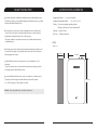
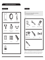
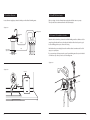
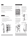
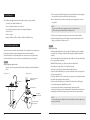
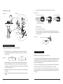
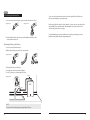
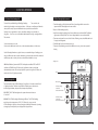
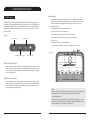
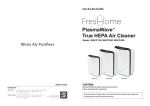
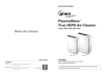
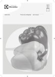
Please contact your dealer for questions regarding your
product and to purchase WINIX Replacement Filters.
2013.02.28
TABLE OF CONTENTS
1.0 WARRANTY
1.0 Warranty
2
2 . 0 S a f e t y I n s t r u ct i o n s
3
3 . 0 S p e ci f i ca t i o n & D i m e n s i o n s
4
4 . 0 I n s t a l l a t i o n I n s t r u ct i o n s
5
4 . 1 Pack age contents
5
4 . 2 Tools needed
6
4 . 3 Installation overview
7
4 . 4 Turn of f w ater supply
8
4 . 5 Determine the installation location
8
4.6 Drilling
9
4 . 7 Faucet mounting
9
4 . 8 4 . 8 M ounting Brack et System Installation
10
4 . 9 Install batteries
11
4 . 1 0 C old w ater supply f itting
11
4 . 1 1 M ak ing tubing connections
13
4. 1 2 C onnect w ater lines
14
4 . 1 3 A ttaching the Diverter V alve
15
5 . 0 Fi l t e r C a r t r i d g e
17
5 . 2 UF C artridge Lif e
17
5 . 3 Filter C artridge Replacement
6 . 0 R e p l a ce m e n t I n d i ca t o r
6 . 1 FC SPU1 Indicator
7. 0 T r o u ble sh o o t in g
1
17
5 . 1 C arbon Filter C artridge Lif e
18
19
19
21
ONE YEAR LIMITED WARRANTY ON FINECEL WATER FILTRATION SYSTEM
[EXCLUDING FILTER CARTRIDGES]
Warrantor: Winix Inc., 120 Prairie Lake Rd Unit E, East Dundee, IL 60118
Warrantor guarantees, to the original owner, that the FINECEL Water Filtration System, when
installed and maintained in accordance with the instructions, will be free from defects in
materials and workmanship for a period of one year from date of installation. If, within the first
year, a part proves, after inspection, to be defective, Warrantor will, at its sole option, either
replace or repair the part without charge except normal shipping and installation charges. Labor
to maintain the equipment is not part of the warranty. Filters, which are expendable, are not
covered by the warranty.
TO OBTAIN WARRANTY PARTS, SIMPLY CALL 1-877-MY-WINIX (699-4649), Monday - Friday,
8 am - 5 pm CST, for assistance. This warranty applies only while this product is in use in the
United States or Canada.
General Provisions
The above warranties are effective provided the FINECEL Water Filtration System is operated at
water pressures not exceeding 100 psi, and at water temperatures not exceeding 100 ℉
provided further that the FINECEL Water Filtration System is not subject to abuse, misuse,
alteration, neglect, freezing, accident or negligence; and provided further that the FINECEL
Water Filtration System is not damaged as the result of any unusual force of nature such as, but
not limited to, flood, hurricane, tornado or earthquake.
Warrantor is excused if failure to perform its warranty obligations is the result of strikes,
government regulation, materials shortages, or other circumstances beyond its control.
*THERE ARE NO WARRANTIES ON THE FINECEL WATER FILTRATION SYSTEM BEYOND THOSE
SPECIFICALLY DESCRIBED ABOVE. ALL IMPLIED WARRANTIES, INCLUDING ANY IMPLIED
WARRANTY OF MERCHANTABILITY OR OF FITNESS FOR A PARTICULAR PURPOSE, ARE
DISCLAIMED TO THE EXTENT THEY MIGHT EXTEND BEYOND THE ABOVE PERIODS. THE SOLE
OBLIGATION OF WARRANTOR UNDER THESE WARRANTIES IS TO REPLACE OR REPAIR THE
COMPONENT OR PART WHICH PROVES TO BE DEFECTIVE WITHIN THE SPECIFIED TIME PERIOD,
AND WARRANTOR IS NOT LIABLE FOR CONSEQUENTIAL OR INCIDENTAL DAMAGES. NO
WARRANTOR DEALER, AGENT, REPRESENTATIVE, OR OTHER PERSON IS AUTHORIZED TO
EXTEND OR EXPAND THE WARRANTIES EXPRESSLY DESCRIBED ABOVE.
Some states do not allow limitations on how long an implied warranty lasts or exclusions or
limitations of incidental or consequential damage, so the limitations and exclusions in this
warranty may not apply to you. This warranty gives you specific legal rights, and you may have
other rights which vary from state to state. This warranty applies to consumer-owned
installations only.
2
2.0 SAFETY INSTRUCTIONS
3.0 SPECIFICATIONS & DIMENSIONS
Read all steps and guides carefully before installing and using your Water Filtration System.
Supply water Pressure :
Follow all steps exactly to correctly install. Reading this manual will also help you to get all the
Supply water temperature limits :
benefits from the Water Filtration System.
20~100 psi (140~689kPa)
33 ~100 F (0.6 ~38℃ )
Tubing : 1/4” quick connect fittings and tubing included
(Tubing is not Performance Tested or Certified by NSF)
Do not attempt to use this product to make safe drinking water from non-potable water
Capacity : 400 gal (1513 liters)
sources. Do not use the system on microbiologically unsafe water, or water of unknown
Flow rate : 0.5 GPM (1.89 liters/min)
quality without adequate disinfection before or after the system.
This system is certified for cyst reduction and may be used on disinfected water that may
contain filterable cysts.
FCSPU1
<Figure 3.0.1>
Check with your state and local public works department for plumbing and sanitation codes.
You must follow their guides as you install the system. Follow your local codes if they may
differ with guides in this manual.
4.13 Inches
11.97 Inches
The Water Filtration System works on water pressures of 20 psi (minimum) to 100 psi
(maximum).
If your house water pressure is over the maximum, install a pressure reducing valve in the
water supply pipe to the Water Filtration System.
Do not install the Water Filtration System outside, or in extreme hot or cold temperatures.
Temperature of the water supply to the Water Filtration System must be between
16.40 Inches
33 ~100 F(0.6-38 degrees C). Do not install on hot water.
WARNING : When using Saddle Valves, check with local ordinances.
3
4
4.0 INSTALLATION INSTRUCTIONS
4.1 Package Contents
4.2 Tools Needed
<Figure 4.1.1>
NOTE
Gather the required tools before starting installation. Read and follow the
instructions provided with any tools listed here.
<Figure 4.2.1>
Water Filtration System
3/8” Adapter Valve
1/4” Tubing
Faucet valve for counter
-top mounting
Faucet Kit
(See Figure 4.7.1 for expanded view)
Tape Measure
Adjustable Wrench
Phillips / Slotted Screwdrivers
Drill & Drill Bits, if required
Cutter
Leveler
bracket / screws
1/2”
1/4”
Batteries
Locking clip
Saddle Valve
Marking pen
Brasscap
5
IMPORTANT: To avoid damaging the sink or counter, consult a qualified plumber or installer
for drilling procedures in porcelain, stainless steel, granite, quartz or some other special material.
WINIX is not responsible for any damage that occurs due to improper installation of the unit.
6
4.3 Installation Overview
4.4 Turn Off The Water Supply
Locate cold water supply pipe, under the sink that you wish to filter for drinking water.
Before you begin, close the cold water/water supply valve that feeds water to your tap.
Then open the faucet to drain water from the sink cold water pipe.
<Figure 4.3.1>
Aux (Refrigerator)
Filtered Water
Faucet
4.5 Determine The Installation Location
Sink
Determine the location where you intend to install the drinking water faucet. Make sure it is far
enough away from the main faucet so that they don’t interfere with each other-yet in a good
location for filling pitchers or pots of water for cooking.
Outlet
Hot
Most kitchens have a pre-existing hole near the main faucet that is sometimes used for a dish
sprayer, or soap dispenser.
Inlet
Water supply
adaptor valve
Cold
If you are removing a dish sprayer to make room for your drinking water faucet, we’ve included
a 1/4 inch brass cap so that you can close off the existing stem.
<Figure 4.5.1>
<Figure 4.3.2>
Tie Strap
Inlet
Outlet
Brasscap
Hot
7
Cold
8
4.8 Mounting Bracket System Installation
4.6 Drilling
If you need to drill a new hole for your drinking water system, take the base cover off the faucet
and place it where you want to install the drinking water faucet, and then mark the location.
To avoid damaging the sink or counter, consult a qualified plumber or installer for drilling
procedures in porcelain, stainless steel, granite, quartz or some other special material. WINIX is
not responsible for any damage that occurs due to improper installation of the unit.
1. Remove plastic panel on back at
perforation with slotted screwdriver
<Figure 4.8.1>
Before drilling, check for obstructions underneath the sink where the hole will be drilled. Make
sure it is clear and safe to drill.
Use a 1/2inch drill bit to drill the hole
2. Measure proper dimensions for bracket
placement. Do not place bracket closer
than 5 inches to front or back of cabinet
wall, 8 inches from countertop or 12 inches
from cabinet floor. For best results install
on the side of the cold water source.
Mark holes for bracket and drill
(if necessary) and attach brackets with
screws provided with a phillips
screwdriver.
<Figure 4.8.2>
4.7 Faucet Mounting
IMPORTANT: When using a flat tip
screwdriver break each tab individually
with a prying action.
(Faucet is not Performance Tested or Certified by NSF)
1. Insert Base, Rubber washer and Gasket onto mounting bolt on faucet.
2. Insert mounting bolt through the drilled hole in fixture.
3. Place Lock Washer Fixing Nut onto mounting bolt, position faucet on fixture, then
tighten nut securely Make sure the faucet is properly positioned on the counter top.
4. Connect flexible hoses to supply stops.
<Figure 4.7.1>
3. Place unit above bracket and slowly set into
place, aligning hooks on the bracket to the
slots on the case. Push down slightly to fit
securely. You may need to tilt the bottom
of unit forward slightly when placing on
bracket. The unit is secured when it no
longer shifts from left to right.
4. To remove filter and case simply tilt the
bottom of the case forward and lift up.
<Figure 4.8.3>
Base Cover
<Figure 4.8.4>
Gasket
Mounting Surface
Washer
Lock Washer
Fixing Nut
NOTE
The unit is designed to function when not mounted. Mounting is optional but recommended.
9
10
1. Close the water shut off valve/angle stop that is immediately in front of the supply tube
and open the faucet to drain water from the sink cold water pipe.
4.9 Install Batteries
2. Remove the nut that connects the cold water faucet to the supply tube. Some water
may spill out.
These will power the lights and other alerts that tell you when to change your filters
1. Push the ”open” button of the filter case.
2. Press and slide open battery cover in red circle
NOTES
Be sure to turn off the water supply and open a faucet to drain the pipe.
Make sure the gasket is installed in the 3/8” Adapter Valve.
3. Insert batteries with proper positive(+) and negative(-) alignment
4. Close the cover
Power on sequence
3. Thread the 3/8” adapter valve onto pipe and reconnect nut to bottom of fitting.
Battery in->LED1 on->LED2 on->LED3 on->LED4 on->LED all off->Beep
4. Install 1/4” tubing. Make sure that 1/4” tubing is securely inserted into quick connect
fittings. You should not be able to remove it.
4.10 Cold Water Supply Fitting
Option 2
Install saddle valve
There are two options to install a cold water feed line. The method that we recommended is to
use the angle stop adaptor valve to simply divert water from the cold water line.
The other method is to use self piercing saddle valve, however, prior to using this method,
we recommend that you check to ensure its use is permitted under your local ordinances.
Option 1
A typical connection using the included adapter valve fitting is shown in the illustration
below.
2. If installing on iron pipe, drill a 1/8” hole for the piercing pin.
3. Clean the section of the pipe that the saddle valve will be placed on.
4. Turn the valve handle all the way out. (counter-clockwise) Be sure the piercing pin does
not stick out beyond the seal.
<F i g u r e 4 . 1 0 . 2 >
Cold Water Faucet Stud/
Flexible Tubing
Filtered Water
Faucet
5. Place the saddle valve on the cold-water pipe over the cleaned area, Tighten the bottom
bolt until the valve is firmly mounted on the pipe.
6. Turn the valve handle all the way in. (clockwise) This will pierce the wall of the pipe.
7. Connect the tubing to the fitting like below picture.
3/8" Adapter Valve
Sink
1. Review and familiarize yourself with all parts of the saddle valve. This valve will self-tap a
hole in copper tubing or plastic pipe.
IMPORTANT: Before starting, close the hot and cold water shutoff valves.
Install angle stop adaptor valve.
<F i g u r e 4 . 1 0 . 1 >
This fitting will be installed on the cold water pipe. The fitting must provide a leak-tight
connection to the 1/4” tubing. Complete the following steps to install the saddle valve
assembly.
8. Open the water shutoff valve(s) and start turning the saddle valve handle
counterclockwise until you see water running from the attached tubing. Control the flow
by turning the valve handle. After testing, close the valve and work on your appliance.
1/4” Tubing to
Water Filter Inlet
Hot
11
Cold
Cold Water Shutoff/
Angle Stop Valve
NOTE
Once the saddle valve is installed, the nut near the handle may need to be tightened to
prevent possible leaks.
12
Saddle Valve Connections
6. Insert plastic tab to ensure quick connect fitting cannot come as done.
<Figure 4.11.2-4>
<Figure 4.10.4>
<Figure 4.10.3>
Tubing correctly cut and connected
Filtered Water
Faucet
Bottom
bolt
Incorrect partial engagement
Nut
1/4”tubing
Ferrule
(Plastic)
Sink
Insert
Valve
Nut-tighten
if necessary
Hot
Cold
Handle
use to connect
tubing
end of tubing round and smooth.
with no cuts, nicks or flat spots
correct full 3/4”
To Disconnect Tubing :
1. Remove plastic tab from fitting
2. Push the collet inward and hold with a finger while pulling the tubing out. Make sure
the collet is pushed evenly on all sides. If only one side is pushed the tubing will not be
able to be removed.
<Figure 4.11.5>
collet (depress to remove tubing)
tubing
4.11 Making Tubing Connections
(Tubing is not Performance Tested or Certified by NSF)
1. Measure 3/4” from the end of each remaining piece of tubing (faucet end and inlet
end) and mark with a pencil (Check for roundness, smoothness, cuts, nicks, flat spots
and sharp edges.)
CORRECT
INCORRECT
<Figure 4.11.1>
2. Push the tubing firmly into each fitting on the manifold until the line is flush with the
fitting collar. (If the tubing is removed, re-cut the end, measure, mark and re-insert).
Tubing must be fully inserted to avoid leaks (To remove tubing, depress and hold white
collet; pull tubing out to remove.)
4. Pull out slightly on tubing to ensure a good seal. Do no pull too hard or it may damage
related parts.
5. Install the other end of the tubing from the inlet side of the manifold to the feed water
adapter.
13
4.12 Connect Water Lines
IMPORTANT:
Remove plastic plugs from water line inserts.
To connect the water lines, begin by taking the plastic supply line form the angle stop or saddle
valve and firmly connect it to the left most quick connect the on the top of the Fincel system
labeled “In”, Push the water line in completely and gently pull back out until it stops. Then
insert a blue locking clip to secure it.
Take the second feed line and repeat the process with the middle quick connect labeled "Out".
Leave the auxiliary cap in if you’re not using it to supply another faucet or appliance.
Take the free end of the second “Out” feed line and firmly attach it to the quick connect at the
base of the drinking faucet stem. Assure it’s properly connected like before and attach a blue
locking clip
14
Option 3
4.13 Attaching the Diverter Valve
1. Unscrew to remove the aerator(wire screen) and washer from the end of faucet.
<Figure 4.13.1>
<Figure 4.13.2>
You are now ready to turn the water main back on. As the system fills, check for leaks and
make sure that everything is connected properly.
Run the water to flush the system for about 2 minutes. You may notice some carbon dust in the
water initially. This is normal and harmless. After flushing the system you should be able to
check for clarity of the water in a clear glass
2. Position the Diverter Valve onto the faucet and hand tighten the textured collar
counterclockwise until secure.
Your Fincel drinking water system from Winix is now ready for use;providing you and your
family with clean, healthy and great tasting drinking water.
Attaching the Tubing to the Diverter
1. Unscrew to remove the textured nuts.
2. With the threads facing out, push the nuts onto the tubes.
<Figure 4.13.3-5>
Inlet
Outlet
3. Firmly push the tubes onto the barbs.
4. Screw the nuts onto the barbs and hand tighten.
5. Use the Tie Straps to secure the tubing to the faucet.
Tie Strap
<Figure 4.13.6>
Inlet
Outlet
NOTE
Do not run hot water through system damage to filters will occur.
15
16
5.0 FILTER CARTRIDGE
5.1 Carbon Filter Cartridge Life
5.3 Filter Cartridge Replacement
Taste and Odor, and Microbiological Purifying Cartridges:
Taste and odor, and
microbiological cartridges contain activated carbon . When new, a small amount of harmless
carbon particles may be present in the filtered water. Open the faucet and flush for
2 minutes. It is recommended to replace carbon filter cartridges every six months or
400 gallons of use. There are several variables that determine how long a cartridge will last.
These include:
1. Turn filter cartridge to left (clockwise) until “Insert” arrow aligns with the arrow on the
system manifold. Pull straight down to remove filter.*
1. How much water you use, and
5. Flush filter unit for at least 2 minutes prior to use.
2. How much sediment, taste and/or odor, or other unwanted substance, is in the water.
* Turn water off at plumbing connection first. While not necessary, it can reduce potential
leaking
2. Dispose of filter cartridge properly.
3. Install new cartridge by aligning “Insert” arrow with the arrow on the manifold. Turn filter to
right (counter clockwise) until “Lock” arrow is aligned with the arrow on the manifold.
4. Turn water and system faucet on to check for leaks. If leaking occurs, reinstall filter and check
for proper arrow alignment.
Use the following information as a guide. However, no matter which type of cartridge you are
using, you will know it is time to replace them when you first notice the return of the unwanted
sediment, taste and/or odor in your water, or when the flow diminishes or stops.
<Figure 5.3.1>
WINIX Water Filtration System model FCSPU1 with replacement filters SPCF1 and SPUF1
conforms to NSF/ANSI 42 and 53 for the specific performance claims as verified and
substantiated by test data. The rated capacity for this system is 400 gallons (1513 liters) at a
rated service flow of 0.5 gallons per minute.
Head
5.2 UF Cartridge Life
Filter cartridge
The rated capacity for the UF Filter Cartridge is 1200 gallons or 18 months at a rated flow of
0.5 gallons per minute. This filter is responsible for a filtration process that removes:
microbiological pollutants, heavy metals, and many other pollutants.
IMPORTANT: The UF Filter Cartridge must be operate when water is between
33° and 100° F.
WARNING: The UF Filter Cartridge will be damaged if frozen. The UF Filter Cartridge
must be kept above temperatures of 32°F (0°C). Failure to do so may cause the
UF Filter Cartridge to dry, freeze, become damaged, and will void all warranties. Operating
a damaged system may lead to personal injury and/or physical harm.
17
Turn filter cartridge
to the left to
remove from manifold
Turn filter cartridge
to the right to
attach to head manifold
Filter
A
Filter
B
Filter
C
18
6.0 REPLACEMENT INDICATOR
Battery Indicator
6.1 FCSPU1 Indicator
The FINECEL Water Filtration System is equipped with a replacement indicator that measures
both total flow of water AND the length of time each filter has been in use. There will be both a
visual and audible signal to alert you to when each filter's life has been reached and when the
total system is nearing the recommended capacity of 400 gallons for carbon filters and 1200
gallons for UF filter.
When the timer reaches approximately 18 months of use, it will flash. At this time it is
recommended to replace battery. When the batteries are installed for the first time, the
indicator display will beep and flash all indicator lights to ensure the user they are
functioning correctly.
To change the battery, complete the following steps.
1. Push the “Open” button top of the filter case.
2. Press and slide open battery cover in red circle (shown below).
<Figure 6.1.1>
Pre Filter Indicator
Post Filter Indicator
3. Insert batteries with proper positive(+) and negative(-) alignment.
4. Close the cover.
5. Push the reset button “B” to reinitialize indicator.
(you can see the small hole around “B”, push it with fine wire for 3 seconds)
<Figure 6.1.2>
UF Membrane Filter Indicator
Low Battery Indicator
Pre Filter/ Post Filter Indicator
It is recommended to replace pre filter and post filter cartridges at least every 6 months of
product water use. When the timer reaches 6 months, the LED indicator will turn on under
A and C on readout and the unit will beep intermittently. Indicator will be automatically
reset after replacing filter.
Whole system
reset button
UF Membrane Filter Indicator
It is recommended to replace Ultra Filtration Membrane filter cartridge at least every 18
months of product water use. When the timer reaches 18 months, the LED indicator will
turn on under B on the readout and the unit will beep intermittently. Indicator will be
automatically reset after replacing filter.
NOTE
If filters are replaced before the indicator light is activated, you must manually reset the
filter indicator lights. To do this insert a paperclip into the hole next to the
corresponding filter letter.
The large hole located to the far left of the indicator display is a full system reset. This
hole will be used if all three filters are changed before their indicator lights are active.
This allows for the user to reset all sensors simultaneously.
19
20
7.0 TROUBLESHOOTING
Problem: Chlorine taste and/or odor in the filtered water.
Problem: Water leaks at push connect fittings.
Cause: The level of chlorine in your water supply exceeds maximum limits, and has
Cause: Tubing not pushed in all the way.
destroyed the Ultra Filtration membrane.
Correction: Push tubing in all the way into fittings.
Correction: If the water supply contains more than 2.0 ppm of chlorine, additional
filtering of the water supply to the UF is needed. Correct this condition before doing
maintenance on the Ultra Filtration system.
Cause: The pre filter is no longer reducing chlorine from the water supply.
Correction: Replace the pre filter, post filter and Ultra Filtration membrane cartridges.
Cause: Tubing not cut square.
Correction: Cut tubing square.
Cause: Tubing nicked.
Correction: Remove nicked portion, reinsert tubing into fitting.
Cause: Outer tubing surface not smooth.
Problem: No water or decreased water flow.
Correction: Remove rough portion, reinsert tubing into fitting.
Cause: Pre-Filter A is clogged.
Correction: Replace Pre-Filter A.
Cause: Flow through the microbiological purifying filter will decrease and eventually clog
when exposed to an excess of microbiological loading materials in the water.
Problem: Tubing does not connect to water filtration system.
Cause: Black plugs are still connected to the unit.
Correction: Remove black plugs and insert tubing into fitting.
This failsafe feature reduces the chance of product use beyond its intended life, and will
shut down the filter when it is exposed to contaminated water.
Correction: Replace all filter cartridges.
Problem: Taste and/or Odor.
Cause: Filter cartridges exhausted.
Correction: Replace all filter cartridges.
Cause: System contaminated.
Correction: Sanitize system. Call location of purchase for instructions.
Problem: FCSPU1 LED indicator light does not function after battery change.
Cause: Battery dead.
Correction: Replace with new battery.
Cause: Battery installed incorrectly.
Correction: Install battery correctly.
21
22