1
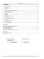
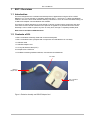
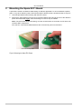
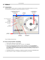
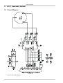
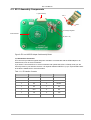
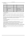
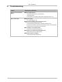
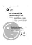
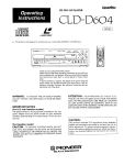
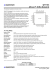
LQ
w w w . q p r o x . c o m
E511
User Manual
The New Vision of Touch
TM
E511 User Manual
Contents
1
E511 Overview........................................................................................................................3
1.1
1.2
Introduction ....................................................................................................................................................................................3
Contents of Kit ...............................................................................................................................................................................3
2
Mounting the Spare E511 Board ...........................................................................................4
3
Setting Up the E511 ...............................................................................................................5
4
QWheel ...................................................................................................................................6
4.1
4.2
4.3
Introduction ....................................................................................................................................................................................6
How to Use the E511 Assembly ....................................................................................................................................................6
QWheel Parameters ......................................................................................................................................................................7
5
E511 Assembly Details ..........................................................................................................8
5.1
5.2
Circuit Diagram ..............................................................................................................................................................................8
E511 Assembly Components.........................................................................................................................................................9
6
Troubleshooting...................................................................................................................11
List of Figures
Figure 1: Evaluation Assembly and USB-SPI Adapter Card............................................................................................................................................3
Figure 2: Mounting the Spare E511 Board.......................................................................................................................................................................4
Figure 3: E511 and USB Connectors...............................................................................................................................................................................5
Figure 4: QWheel Information Areas................................................................................................................................................................................6
Figure 5: E511 Circuit Diagram ........................................................................................................................................................................................8
Figure 6: E511 and USB-SPI Adapter Card Assembly Details ........................................................................................................................................9
List of Tables
Table 1: J1, SPI Interface Connector ...............................................................................................................................................................................9
Table 2: UI (QT511 IC)...................................................................................................................................................................................................10
Corporate Headquarters
North America
1 Mitchell Point
Ensign Way, Hamble
Southampton SO31 4RF
United Kingdom
651 Holiday Drive Bldg. 5 / 300
Pittsburgh, PA 15220
USA
Tel
Fax
Tel
Fax
+44 (0)23 8056 5600
+44 (0)23 8045 3939
2 of 12
412-391-7367
412-291-1015
E511 User Manual
1
E511 Overview
1.1 Introduction
This kit is designed for the evaluation and development of applications using the QT511-ISSG
QWheel™ IC. The kit includes an evaluation assembly (E511 – see Figure 1), cables and QWheel
software. The E511 has a serial interface allowing connection to a PC for control and data viewing via
a USB to SPI adapter card and QWheel PC software.
This unique IC allows designers to create speed or volume controls using a wheel/rotor and other
more exotic forms of human interface on the panel of an appliance or personal electronic device.
Generally it can be used to replace any form of rotary knob, through a completely sealed panel.
Refer also to the QT511-ISSG datasheet.
1.2 Contents of Kit
1 x E511 evaluation assembly, fitted with conductive backplate
1 x E511 evaluation board (complete with components and self-adhesive on one side)
1 x USB-PC cable
1 x USB-SPI adapter card
1 x 14-way flat flexible cable (FFC)
2 x sample QT511-ISSG ICs
1 x CD-ROM containing QWheel software, User Manual and Datasheet
FFC cable
USB-SPI
adapter card
E511 evaluation
assembly
Figure 1: Evaluation Assembly and USB-SPI Adapter Card
3 of 12
E511 User Manual
2
Mounting the Spare E511 Board
A spare E511 board is included to allow testing on different applications. It can be adhered to plastic,
glass, or any other dielectric panel. Follow these steps to attach the E511 board and refer to Figure 2:
1. Use ESD precautions when working with the E511 board.
2. Remove the paper backing from the E511 board and adhere the board to the rear of the dielectric
panel. Bend the board slightly, while smoothing it to remove any air bubbles.
Note: The board does allow some flexing, but care must be taken not to bend it too far as this can
crack the SMT components.
Also, the four corner M3 threaded fasteners are connected to ground on the board.
remove the backing paper
bend the board slightly
Figure 2: Mounting the Spare E511 Board
4 of 12
E511 User Manual
3
Setting Up the E511
To prepare the E511 for use, proceed as follows:
1. Using the flat flexible cable (FFC) provided, connect the E511 assembly to the USB-SPI adapter
card, ensuring correct orientation of the FFC. With the E511 connector lock open (Figure 3),
carefully insert the end of the cable into the connector. Once fully inserted, push the connector
lock tabs to close them. Check that they are fully engaged. Repeat for the USB-SPI adapter card.
2. Using the USB cable provided, connect the USB-SPI adapter card to the PC. LED 1 lights
constantly to indicate that there is power to the card.
3. Install the software; either method is acceptable:
a. Put the supplied CD in the CD drive of the PC. Copy the contents of the CD to your PC.
Double-click the QWheel software to open it.
OR
b. Go to www.qprox.com, point to the Support tab and click Download Archive. Click Software
and then the QWheel link. A dialog box appears asking if you want to run or save the file that
you are about to download. Click Run. This automatically downloads the software.
If a dialog box appears saying “The publisher could not be verified. Are you sure you want to
run this software?” click Run.
4. QWheel software is displayed on the PC screen. LED 1 now flickers continuously to indicate that
QWheel is communicating with the E511 assembly. Refer to Section 4.2, Page 6 about using the
E511.
connector lock
engaged
connector lock
open
E511 assembly – connector lock open
E511 assembly – connector lock engaged
connector lock
engaged
connector lock
open
USB card – connector lock open
USB card – connector lock engaged
LED 1
USB card
USB cable to PC
Connections between USB card and PC
Figure 3: E511 and USB Connectors
5 of 12
E511 User Manual
4
QWheel
4.1 Introduction
QWheel software is used for the E511 evaluation assembly. With QWheel software you can send
commands and monitor signals in real time (see Sections 4.2 and 4.3).
Connected/Disconnected indicator
Shows when the E511 is
connected to the PC
(see Page 7)
Threshold
(see Page 7)
Wheel indicator
Shows the last reported
touch position
(see Page 7)
Drift Compensation Rate
(see Page 7)
Detection
(see Page 7)
Signal Error indicator
(see Page 7)
Calibrate
(see Page 7)
Status Bar
(see Page 7)
Output Ratio
(see Page 7)
Command Return
(see Page 7)
Figure 4: QWheel Information Areas
4.2 How to Use the E511 Assembly
1. Place the E511 assembly on a level surface.
2. At the start of each session, keeping clear of the E511, click Calibrate.
3. Move your finger around the wheel area of the E511 assembly. As you do so the Detection
indicator lights, Output Ratio shows the numerical wheel position and Command Return gives
the hexadecimal equivalent. When you remove your finger, the last position touched will be locked
on the display. LED 2 on the USB card lights every time the E511 assembly is touched, for the
duration of the touch.
4. If the QWheel software is not detecting, or detection is sporadic, decrease the Threshold slightly.
5. Refer to Section 4.3, Page 7 for details of which parameters you can change.
6 of 12
E511 User Manual
4.3 QWheel Parameters
Refer to Figure 4, Page 6 to see the parameter areas of the QWheel software.
(refer to the QT511-ISSG datasheet for more information)
Connected/Disconnected indicator is alight all the time that the E511 is connected to the PC but
goes out when the E511 is disconnected from the PC.
Threshold sets the amount of signal change which will cause the E511 to register touch detection.
The default = 25. Click the Threshold arrow and select a new threshold, if required.
Drift Compensation Rate sets the adaptive drift compensation rate. The numbers represent seconds
per reference level. The default = 5. Click the Drift Compensation Rate arrow and select a new rate,
if required.
Detection indicator lights when a touch is detected on the E511 assembly and goes out when the
touch is removed.
Wheel indicator moves as you move your finger around the E511 wheel. When the touch is removed
the wheel indicator shows the last reported touch position. The indicator does not move when only
proximity is detected.
Note: if Threshold is set to a very low level, the indicator may move if the user’s hand is in close
proximity.
Signal Error indicates that the signal has the wrong polarity, usually due to E511 assembly
movement. Clicking Calibrate will resolve the error.
Calibrate - calibration should be performed with the E511 assembly in the position in which it will be
used, with hands at a distance, to get a valid reference level. Once positioned, click Calibrate to
calibrate the E511 assembly.
Note: if the conductive backplate has been removed, recalibrate the E511 every time that the board is
moved.
Output Ratio shows the numerical wheel position, with touch, from 0 to 127. This changes in real time
as the position of touch on the E511 wheel changes.
Command Return represents the QT511’s response status byte in hexadecimal. This is useful for
diagnostic purposes. It changes in real time as the position of touch on the E511 wheel changes.
The Status Bar indicates if the USB is connected and also which version of QWheel software is
present.
7 of 12
E511 User Manual
5
E511 Assembly Details
QT511-ISSG
5.1 Circuit Diagram
Figure 5: E511 Circuit Diagram
8 of 12
E511 User Manual
5.2 E511 Assembly Components
J1 (SPI Interface)
LED 1
LED 2
U2 Voltage Regulator
Wheel Element
UI (QT511 IC)
Figure 6: E511 and USB-SPI Adapter Card Assembly Details
J1, SPI Interface Connector
This connector provides all signals and power needed to communicate with the USB adapter or an
external host, such as a microcontroller.
If you wish to connect the E511 to a microcontroller and operate the QT511 in Sleep mode you will
need to provide in your interface circuit a 1nF capacitor between DETECT (J1 pin 10) and GND. Refer
to the QT511 datasheet for more information.
Table 1: J1, SPI Interface Connector
Pin
Name
Pin
Name
1
N/C
8
SDI
2
N/C
9
DRDY
3
N/C
10
DETECT
4
N/C
11
N/C
5
SDO
12
N/C
6
/SS
13
VSS
7
SCLK
14
VIN
9 of 12
E511 User Manual
U1, QT511 IC
Table 2: UI (QT511 IC)
Pin
Name
Pin
Name
1
VDD
8
SNS2A
2
SDO - serial data (output)
9
SNS1B
3
/SS - slave select (input)
10
SNS1A
4
SCLK - serial clock (input)
11
SDI - serial data (input)
5
SNS3B
12
DETECT - active high (output)
6
SNS3A
13
DRDY - data ready (output)
7
SNS2B
14
VSS
U2, Voltage Regulator
The E511 uses a Low Dropout (LDO) regulator to regulate the 5V coming from the USB adapter card
down to 3.3V.
Resistor R25 is not usually fitted to the Quantum evaluation board because the Quantum-provided
regulator is very stable. However, in certain circumstances if other regulators are used, R25 may be
fitted.
Since the QT511 works on a lower voltage (3.3V) than the USB card (5.0V), the signals from the USB
card to the E511 must be level-shifted down. This is done using resistive dividers R20, R21 and R22,
plus a set of resistors placed in series with the signal lines on the USB card.
Wheel Element
The wheel element is resistorless and consists of etched copper electrodes. For more information
refer to the QT511 datasheet.
Sampling Capacitors
C1, C2 and C5 are the Cs sampling capacitors. Increasing their value will increase sensitivity and
resolution of measurement, but will also tend to make the response time slower.
Conductive Backplate – this is fitted to allow the E511 assembly to be picked up without false
detections occurring and without having to recalibrate every time it is moved. If the backplate is
removed, the E511 assembly cannot be picked up without these happening.
LED 1 (on USB card) – before the QWheel software is running, LED 1 will be on constantly, to indicate
that the USB card is connected to the PC and has power (see Figure 6). Once the QWheel software is
running, LED 1 flickers continuously to indicate that the software is communicating with the E511
assembly.
LED 2 (on USB card) – stays on when the E511 assembly is touched, for the duration of the touch
(see Figure 6).
10 of 12
E511 User Manual
6
Troubleshooting
Problem
Potential Cause and Solution
Software will not communicate
with PC
! Bad SPI or USB connection
Check that the USB cables are connected properly.
Check/replace cables
Ensure that the E511 assembly is getting power and the USB card LED 1 is on
Noisy or erratic signal
! Noisy power supply
Try a different USB port or PC
! Cables or E511 assembly too close to strong noise source
(such as a power line or switching noise source)
Increase the distance between the E511 assembly and the noise source
Ensure that the backplate is fitted and securely screwed to the four corner M3 threaded
fasteners (these are connected to ground on the board)
! E511 assembly is not mechanically stable
Prevent E511 assembly from moving around
! Strong RFI from a transmitter or adjacent digital product
Remove the noise source or shield against it
! USB cable connected via a USB hub
Connect the USB cable directly to the PC
11 of 12
LQ
Development Team
w w w . q p r o x . c o m
Martin Simmons, Keith Britton, Matthew Trend
Corporate Headquarters
North America
1 Mitchell Point
Ensign Way, Hamble
Southampton SO31 4RF
United Kingdom
651 Holiday Drive Bldg. 5 / 300
Pittsburgh, PA 15220
USA
Tel
Fax
Tel
Fax
+44 (0)23 8056 5600
+44 (0)23 8045 3939
Copyright © 2006-2007 QRG Ltd
All rights reserved
Patented and patents pending
412-391-7367
412-291-1015
REV 200.0107