1
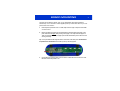
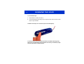
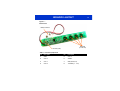
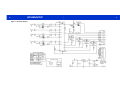
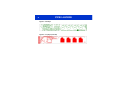
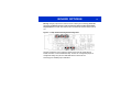
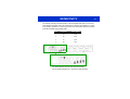
13
E240
User Manual
The New Vision of Touch™
E240
16
User Manual
OVERVIEW
The E240 is designed to let you evaluate and develop with the QT240 4 key QTouch™ IC. It
includes four independent touch sensitive electrodes with corresponding LEDs to indicate
touch. Connections are provided for external interfacing. The E240 is powered from an
external 7V to 12V DC source (such as a common 9V battery).
For more detailed information about this product please refer to the latest QT240
datasheet at www.qprox.com/datasheets.
Materials Provided:
1 x Clear plastic panel
1 x E240 self-adhesive eval board with battery clip
1 x 9V battery
4 x Rubber feet
2 x Sample QT240-ISS chips
1 x QRG product CD-ROM (with QT240 datasheet but check website for latest)
1 x User guide
BOARD MOUNTING
The E240 can be adhered to plastic, glass, or any other dielectric panel with its peel-back
adhesive strip. You do not have to use the supplied panel if you would rather stick it on your own
panel. Here’s how to mount it:
1
Place the plastic panel face down on a table; tape down the edges of the panel to the table
so it cannot move.
2
Remove the peel-back paper from the E240 PCB and adhere the E240 to the back of the
panel. Flex the E240 slightly while pressing down lightly on it to help eliminate trapped air.
Take care to flex the board only slightly to prevent the delicate SMT parts on the board from
cracking and failing.
Tip: Line up the PCB with the alignment marks on the back of the slider panel. The PCB must
be positioned as shown below so that the keys line up with the graphics.
3
Un-tape the board from the table, and mount the four rubber feet as shown above to make
the E240 mechanically stable in use.
1
RUNNING THE E240
2
To run the E240, simply:
1
Place the E240 on a table, touch side up.
2
Connect the 9V battery while making sure your fingers are clear of the touch areas to allow
proper no-signal calibration.
The E240 is now ready to use! Touch the keys to see the LEDs light up.
A continuous touch of 10 seconds will cause the key to recalibrate. Releasing the key
after such an event and waiting a few seconds will cause the key to recalibrate yet again,
and the key will function normally thereafter.
THEORY OF OPERATION
The E240 scans the keys using bursts of charge-transfer pulses. Immediately after power up, the
signals from these bursts are used to calibrate the baseline reference values of the keys. This
makes the device highly adaptive to mechanical differences (i.e. varying panel thicknesses). The
QT240 chip also performs drift compensation on a continuous basis, so that the signals are
constantly being adjusted at a slow rate to accommodate drift.
The calibration process (done at power-up) should be performed in a ‘not disturbed’
neutral condition, i.e. all fingers away from the keys and with the board situated in the
location where it will be used. Changes in location can alter the amount of signal coupling
from the board back to the local environment and thereby change the sensitivity of the
keys. If the calibrations are in error, just leaving the board alone for up to 30 seconds will
allow the drift calibration process to settle the keys into the correct calibration values.
The QT240 features spread-spectrum pulse modulation which heavily suppresses external noise
effects, while also suppressing radiated emissions. This powerful feature provides for highly
reliable, compliant operation under a wide variety of operating conditions.
The QT240 chip also uses a ‘Detect Integrator’ to protect against false detection reporting by
verifying that a key is reporting touch for 6 bursts in a row; if the device fails to detect a touch
during any of these 6 signal samples the chip will refuse to report a key touch on an Out pin.
Combined with spread-spectrum operation, the detect integration process provides a powerful
mechanism to suppress false detections from external noise sources.
If a key is touched for longer than 10 seconds, the key is flagged as a ‘stuck key’ and the QT240
recalibrates it so that the corresponding LED will go out, and the key will operate again normally
while suppressing the object (ie, a touch) that caused the prolonged detection. Only the ‘stuck
key’ is recalibrated, as all electrodes operate independently. The 10s timeout can be changed to
60s or infinite with jumpers; see page 10 for details.
3
4
BOARD DETAILS
The E240 is a simple double-sided PCB on industry standard FR4 material. All parts are
standard surface mount types. Here is a brief description of some of the parts and features.
Keys — Keys consists of capacitive electrodes formed using copper areas on the E240 which
project a capacitive field through the overlying dielectric panel material.
Electrodes — Copper areas on the PCB which define the touch keys.
LEDs — The board has one ‘Power’ LED which remains on as long as the board is powered,
plus one LED per key to indicate touch.
Connector CN1 — The main interface connector is located at one end of the E240 board. The
pinout of this connector is shown in Table 1 (next page). The pin functions are as follows:
[1] SYNC — Not used in fast mode (the default setting). SYNC is available in slow mode
only and is used to synchronize the E240 burst with an external falling edge signal,
usually derived from a 50 or 60Hz source to suppress mains interference, or to allow
two or more QT240 chips to synchronize to to each other, to prevent cross-interference
effects between the adjacent keys of different chips.
[2..5] OUT ‘A’ ~ OUT ’D’ — OUT pins are low when the corresponding key is inactive and
high when active, and are controlled by the QT240 chip. These lines also control the
LEDs.
[6] /RESET — Can be left floating, as the board has its own internal reset circuit. To reset
the E240 externally (for example to force all keys to recalibrate), connect RESET to
GND for at least 1ms, then release it; the board will restart, recalibrate and be ready to
detect touches again after about 180ms.
[7, 8] +POWER, GND — Use +7 to +12VDC connected between the +POWER and GND to
power the E240 board. The battery snap feeds the same two connections, and can also
be used for power input.
BOARD LAYOUT
5
Figure 1 —
Board Layout
Battery Connector
Electrodes
(on user side)
Connector (CN1)
Table 1 — Connector (CN1) Pinout
Pin
Description
Pin
Description
1
SYNC
5
OUT ‘A’
2
OUT ‘D’
6
/RESET
3
OUT ‘C’
7
GND (Ground, 0V)
4
OUT ‘B’
8
+POWER (+7 .. +12V)
6
SCHEMATIC
Figure 2 — Schematic Diagram
7
PCB LAYERS
8
Figure 3 — Silk Layer
Figure 4 — Top Layer (user side)
BOARD OPTIONS
Warning: Changing components on the board involves soldering and unsoldering; please take
care not to overheat the board or to leave excessive flux which can affect signal stability
and performance. If in doubt, clean the board with a commercial flux remover and dry it prior to
use.
Figure 5 — Jumper Positions Showing Default Configuration
The E240 as shipped is factory configured to operate in fast mode with spread spectrum
enabled, and with a 10-second recalibration delay. The user can re-configure the jumpers to
change these settings using zero-ohm 0603 SMD resistors or bits of fine wire.
See next page for available jumper combinations.
9
OPTION JUMPERS
10
Jumpers 1, 2 and 3 set the mode to Fast (40msec response) or Slow (110msec response),
Spread Spectrum, and external sync.
Table 2 — Jumpers 1, 2, 3: Fast, Slow, Spread Spectrum Modes
Description
JMP 1
JMP 2
JMP 3
Fast Mode & Spread Spectrum
B
Yes
B
Fast Mode Only
None
None
B
Slow Mode Only
None
None
A
Slow Mode & External Sync
A
None
A
Factory
Default
Jumpers 4 and 5 set Normal or Toggle mode, and max on-duration time (delay to recal after
prolonged detection).
Table 3 — Jumpers 4, 5: Toggle, Max On-Duration Settings
Output
Mode
Max OnDuration*
JMP 4
JMP 5
Normal
10 secs
B
A
Normal
60 secs
A
B
Normal
Infinite
B
B
Toggle mode
10 secs
A
A
Factory
Default
* Max On-Duration is the amount of continuous detection time before the key auto-recalibrates.
SENSITIVITY
11
The sensitivity of the keys has been tailored to match the supplied plastic panel. To make a key
more sensitive, increase the value of its corresponding Cs capacitor (see chart below). To make
it less sensitive, decrease it’s Cs value. Only use 5% or 10% X7R ceramic capacitors; most other
types will be unstable and give erratic results.
Key #
Cs Capacitor
Factory Default
1
C5
22nF
2
C6
22nF
3
C7
22nF
4
C8
22nF
C9 = Spread Spectrum Capacitor (see next page for details)
C5~C8 = Sample Capacitors (Cs) - increase to increase sensitivity
12
SPREAD SPECTRUM
With Spread Spectrum enabled (factory default configuration), a sawtooth voltage signal is
generated on pin 9 (SYNC/SS) of the QT240; this is used to modulate the QT240’s burst
frequency. As pin 9 ramps up, the sample burst frequency increases. The effect of Spread
Spectrum operation is twofold:
- Peak EMC emissions are reduced by up to 10dB, and,
- The E240’s susceptibility to external interference is reduced by a similar amount.
These benefits are highly significant in all applications. The burst and spread modulation
waveforms are as shown:
The burst frequency centers at ~100KHz. The 2V SPREAD sawtooth causes the oscillator to
sweep about ±7% around the center frequency. If the burst length is adjusted (e.g. by changing
the Cs sample capacitors), the SPREAD signal may need to be tweaked to maintain the ±7%
sweep. The easiest way to do this is to change C9. For longer burst lengths, increase C9
(factory default value is 22nF, X7R type) to maintain a ~2V peak amplitude on the SPREAD
waveform.
TROUBLESHOOTER
15
Does Not
Work
` Power supply too low or connected backwards
Keys Not
Sensitive
Enough
` Keys not calibrated properly
B Recalibrate or let stand for up to 30 seconds to let drift compensation work
on the references
` Cs values need to be adjusted higher (ie, if the panel is too thick etc)
` Power supply problem
Noisy or
Erratic
Operation
` Noisy or unstable power supply
` Supply voltage is too low
` Cables or board too close to a strong noise source (ie, a power line or switcher)
B Increase the distance from the noise source
B Place a grounded shield between the noise source and the E240
` E240 is not mechanically stable
B Prevent board from moving around
14
Development Team:
w w w . q p r o x . c o m
Luben Hristov, Peter Dennis, Matthew Trend
Corporate Headquarters
North America
1 Mitchell Point
Ensign Way, Hamble
Southampton SO31 4RF
United Kingdom
651 Holiday Drive Bldg. 5 / 300
Pittsburgh, PA 15220
USA
Tel
Fax
+44 (0)23 8056 5600
+44 (0)23 8045 3939
Email [email protected]
Tel
Fax
412-391-7367
412-291-1015
Copyright © 2004 QRG Ltd
All rights reserved
Patented and patents pending
REV 201.220904