
1
!"#$%&'$()
*+,- )./0.1
!"#$%& '%"()*%'%#+ "#! ,-#+*-&
./012/34 +5671
'73078 97:2 #0;<5: =>?@@@>A@B
(/C2D7:5 E5:1F/3 #0;<5: =G@
*5HF1F/3 I
(5J25;<5: K@@@
DANIEL
LLLLLLLLLLLLLLLLLLLLLLLLLLLLLLLLLLLLLLLLLLLLLLLLLLLLLLLLLLLLLLLLLLLLLLLLLLLLLLLLLLLLLLLLL
!"#$ %&&& '#$$#()!
+M5 ,/;J73N :5J:515321 73O D7::7321 2M72 P/;J025: J:/Q:7;1 F3 73N
;5OF0;4 1/C2D7:54 CF:;D7:5 73O P/;<F372F/31 2M5:5/C RS!58FH5:7<851ST
;730C7P20:5O <N 2M5 ,/;J73N 73O F3P/:J/:725O F32/ /: 10JJ8F5O <N 2M5
,/;J73N C/: 015 DF2M Q//O1 ;730C7P20:5O <N 2M5 ,/;J73N DF884 03O5:
3/:;78 015 73O P7:5U
FT :5P/Q3FV5 73O 7PP5J2 O7251 C788F3Q /3 /: 7C25: A W7307:N K@@@X
FFT :5P/Q3FV5 73O 7PP5J2 2M5 N57: K@@@ 73O 5H5:N 10PP55OF3Q C/0:2M
N57: 71 857J N57:1X
FFFT :5P/Q3FV5 73O 7PP5J2 K? Y5<:07:N F3 2M5 N57: K@@@ 73O 5H5:N
10PP55OF3Q C/0:2M N57:X
FHT :5P/:O4 12/:54 J:/P5114 15Z053P54 J:51532 73O /02J02 P7853O7: O7251
73O O727 :58725O 2/ O7251 C788F3Q /3 /: 7C25: A W7307:N K@@@4 F3 2M5
17;5 ;7335: 73O DF2M 2M5 17;5 C03P2F/378F2N 71 2M5N O/ /3 /:
<5C/:5 =A !5P5;<5: A??? 73O DF2M/02 5::/:1 /: /;F11F/31X 73O
HT 8/15 3/ C03P2F/378F2N DF2M :51J5P2 2/ 2M5 F32:/O0P2F/3 F32/ 2M5; /C
O7251 /: O727 :58725O 2/ O7251 C788F3Q /3 /: 7C25: A W7307:N K@@@X
J:/HFO5O 2M724 F3 2M5 P715 /C 73N 3/3>P/3C/:;F3Q !58FH5:7<851 2M72 7:5
:520:35O 2/ 2M5 ,/;J73N J:/;J28N C/88/DF3Q OF1P/H5:N /C 2M5 3/3>
P/3C/:;F2N4 2M5 ,/;J73N DF884 72 F21 /J2F/3 73O P/124 :5J7F: /: :5J87P5
10PM !58FH5:7<85 /: :5C03O 2/ 2M5 90:PM715: 2M5 J0:PM715 J:FP5 2M5:5C/:G
+MF1 1M788 <5 2M5 90:PM715:[1 1/85 73O 56P801FH5 :5;5ON C/: <:57PM /C 2M5
C/:5Q/F3Q D7::732NG
#/2DF2M1273OF3Q 2M5 C/:5Q/F3Q4 2M5 ,/;J73N 1M788 3/24 03O5: 73N
PF:P0;1273P51 DM721/5H5:4 <5 8F7<85 C/: 73N O5C5P21 /: 5::/:1 P7015O <NU
;725:F781 /: D/:\;731MFJ ;7O54 C0:3F1M5O /: 1J5PFCF5O <N 2M5 90:PM715:X
3/3>P/;J8F73P5 DF2M 2M5 ,/;J73N[1 F31278872F/3 /: /J5:72F/3
:5Z0F:5;5321X C7F80:5 2/ F312788 73N :5HF1F/31 73O]/: 0JQ:7O51 2/ 2M5
!58FH5:7<851 O55;5O ;73O72/:N <N 2M5 ,/;J73NX 73N ;/OFCFP72F/31 2/
!58FH5:7<851 3/2 J:5HF/018N 702M/:FV5O <N 2M5 ,/;J73N F3 D:F2F3QX 2M5 015
<N 2M5 90:PM715: /C 73N 3/3>702M/:FV5O 1J7:5 /: :5J87P5;532 J7:21 F3
P/335P2F/3 DF2M 2M5 Q//O1 015O F3 P/3^03P2F/3 DF2M 2M5 !58FH5:7<851X /:
2M5 015 /C 2M5 !58FH5:7<851 DF2M 73N M7:OD7:5 /: 1/C2D7:5 3/2 10JJ8F5O <N
LLLLLLLLLLLLLLLLLLLLLLLLLLLLLLLLLLLLLLLLLLLLLLLLLLLLLLLLLLLLLLLLLLLLLLLLLLLLLLLLLLLLLLLLL
LLLLLLLLLLLLLLLLLLLLLLLLLLLLLLLLLLLLLLLLLLLLLLLLLLLLLLLLLLLLLLLLLLLLLLLLLLLLLLLLLLLLLLLLLL
2M5 ,/;J73NG +M5 90:PM715: 1M788 72 788 2F;51 :5;7F3 1/858N :51J/31F<85 C/:
2M5 7O5Z07PN 73O 7PP0:7PN /C 788 F3C/:;72F/3 10JJ8F5O <N F2G "3N 2MF:O
J7:2N P/32532 F3 !58FH5:7<851 1M788 P7::N /38N 2M5 D7::732N 56253O5O <N 2M5
/:FQF378 ;730C7P20:5:G
+.% Y-*%_-$#_ ,-#(+$+)+%( +.% ,-'9"#`[( (-&% "#!
%a,&)($E% b"**"#+` $# *%&"+$-# +- +.% 9%*Y-*'"#,% -Y +.%
!%&$E%*"I&%( "( $+ *%&"+%( +- +.% ,."#_% Y*-' `%"* A??? +`%"* K@@@ -* +.% -,,)**%#,% -Y &%"9 `%"*( +.%*%"Y+%*4 "#!
+.% 9)*,."(%*[( %a,&)($E% *%'%!` Y-* I*%",. +.%*%-YG $# #%E%#+ b$&& +.% ,-'9"#` I% &$"I&% Y-* $#!$*%,+4
,-#(%c)%#+$"&4 $#,$!%#+"& -* (9%,$"& !"'"_%(4 $#,&)!$#_
&-(( -Y )(%4 I)($#%(( $#+%**)9+$-# -* &-(( -Y 9*-Y$+(4
$**%(9%,+$E% -Y b.%+.%* +.% ,-'9"#` ."! #-+$,% -Y +.%
9-(($I$&$+` -Y (),. !"'"_%(G
+M5 C/:5Q/F3Q D7::732N 1M788 :5;7F3 H78FO 032F8 2M5 8725: /C !5P5;<5: =A4
A??? /: /35 N57: 7C25: 2M5 O725 2M72 2M5 !58FH5:7<85 D71 1MFJJ5OG
LLLLLLLLLLLLLLLLLLLLLLLLLLLLLLLLLLLLLLLLLLLLLLLLLLLLLLLLLLLLLLLLLLLLLLLLLLLLLLLLLLLLLLLLLL
LLLLLLLLLLLLLLLLLLLLLLLLLLLLLLLLLLLLLLLLLLLLLLLLLLLLLLLLLLLLLLLLLLLLLLLLLLLLLLLLLLLLLLLLL
*+,-./0123 45,/ 607809
!73F58 $3O012:F514 $3PG
(:);1"
!73F58 $3O012:F514 $3PG 73O !73F58 '5710:5;532 73O ,/32:/8 RS!73F58ST 1M788
3/2 <5 8F7<85 C/: 25PM3FP78 /: 5OF2/:F78 5::/:1 F3 2MF1 ;73078 /: /;F11F/31
C:/; 2MF1 ;73078G <07=,9 30>,5 72 ?0//07.=,5@ ,A+/,55 2/ =3+9=,B@
=7-98B=7C .D, =3+9=,B ?0//07.=,5 2E 3,/-D07.0F=9=.G 07B E=.7,55 E2/ 0
+0/.=-890/ +8/+25, ?=.D /,5+,-. .2 .D=5 307809 07B@ =7 72 ,H,7.@ 5D099
B07=,9 F, 9=0F9, E2/ 07G 5+,-=09 2/ -275,I8,7.=09 B030C,5 =7-98B=7C@ F8. 72.
9=3=.,B .2@ 9255 2E +/2B8-.=27@ 9255 2E +/2E=.5@ ,.-J
9:/O0P2 37;51 015O M5:5F3 7:5 C/: ;730C7P20:5: /: 10JJ8F5: FO532FCFP72F/3
/38N 73O ;7N <5 2:7O5;7:\1]:5QF125:5O 2:7O5;7:\1 /C 2M515 P/;J73F51G
,/JN:FQM2 d K@@@ <N !73F58 '5710:5;532 73O ,/32:/84 ./012/34 +56714 )G(G"G
!"" #$%&'( #)()#*)+, -. /0#' .1 '&$( 2.#3 405 6) #)/#.+78)+ .# 8./$)+ $9 095 1.#4
.# 65 095 4)09( : %#0/&$8; )")8'#.9$8; .# 4)8&09$80" : 2$'&.7' 1$#(' #)8)$*$9%
'&) 2#$'')9 /)#4$(($.9 .1 <09$)" =)0(7#)4)9' 09+ >.9'#."; ?.7('.9; @)A0(; B,C,!,
LLLLLLLLLLLLLLLLLLLLLLLLLLLLLLLLLLLLLLLLLLLLLLLLLLLLLLLLLLLLLLLLLLLLLLLLLLLLLLLLLLLLLLLLL
LLLLLLLLLLLLLLLLLLLLLLLLLLLLLLLLLLLLLLLLLLLLLLLLLLLLLLLLLLLLLLLLLLLLLLLLLLLLLLLLLLLLLLLLLL
'#$$#()!
!73F58 '5710:5;532 73O ,/32:/8 RS!73F58ST D7::7321 788 5Z0FJ;532
;730C7P20:5O <N F2 2/ <5 C:55 C:/; O5C5P21 F3 D/:\;731MFJ 73O ;725:F784
J:/HFO5O 2M72 10PM 5Z0FJ;532 D71 J:/J5:8N 1585P25O C/: 2M5 15:HFP5
F3253O5O4 J:/J5:8N F3127885O4 73O 3/2 ;F1015OG %Z0FJ;532 DMFPM F1
:520:35O4 2:731J/:272F/3 J:5J7FO 2/ !73F58 DF2MF3 2D58H5 RAKT ;/32M1 /C
2M5 O725 /C 1MFJ;532 R5FQM2553 RAeT ;/32M1 C:/; O725 /C 1MFJ;532 C/:
O512F372F/31 /021FO5 /C 2M5 )3F25O (27251T4 DMFPM F1 C/03O 7C25: F31J5P2F/3
<N !73F58 2/ <5 O5C5P2FH5 F3 D/:\;731MFJ /: ;725:F784 DF88 <5 :5J7F:5O /:
:5J87P5O 72 !73F58[1 1/85 /J2F/34 C:55 /C PM7:Q54 73O :520:3>1MFJJ5O 72
8/D512 P/12 2:731J/:272F/3G "88 2:731J/:272F/3 PM7:Q51 73O 56J/:2 C551 DF88
<5 <F885O 2/ 2M5 P012/;5:G b7::732F51 /3 O5HFP51 J0:PM715O C:/; 2MF:O
J7:2N ;730C7P20:5:1 3/2 <57:F3Q 7 !73F58 87<58 1M788 M7H5 2M5 D7::732N
J:/HFO5O <N 2M5 2MF:O J7:2N ;730C7P20:5:G
DA')9+)+ 20##09'5 E =.+)"( FGHI; FGJI 09+ FKII 0#) 20##09')+ 1.# 0
40A$474 .1 '2)9'5E1.7# LFGM 4.9'&(, @&) <090"5N)# *0"*)( 0#)
20##09')+ 1.# '&) "$1) .1 '&) $9('#74)9' 09+ '&) 8."749( 1.# 1$*) 5)0#(,
+M5 D7::732F51 1J5PFCF5O M5:5F3 7:5 F3 8F50 /C 73N 73O 788 /2M5: D7::732F514
56J:511 /: F;J8F5O4 F3P80OF3Q 73N D7::732N /C ;5:PM7327<F8F2N /: CF23511 C/:
7 J7:2FP087: J0:J/15G
!73F58 1M788 <5 8F7<85 /38N C/: 8/11 /: O7;7Q5 OF:5P28N P7015O <N F21 1/85
35Q8FQ53P5G !73F58[1 8F7<F8F2N C/: 73N 8/11 /: O7;7Q5 7:F1F3Q /02 /C4
P/335P25O DF2M4 /: :51082F3Q C:/; 73N <:57PM M5:5/C 1M788 F3 3/ P715
56P55O 2M5 J:FP5 788/P7<85 2/ 2M5 5Z0FJ;532 /: 03F2 2M5:5/C DMFPM QFH51
:F15 2/ 2M5 P87F;G !73F58[1 8F7<F8F2N 1M788 25:;F3725 /35 N57: 7C25: 2M5
O58FH5:N /C 2M5 5Z0FJ;532 56P5J2 C/: /H5:1571 O58FH5:F51 73O 56253O5O
D7::732N J:/O0P21 71 3/25O 7</H5G
$3 3/ 5H5324 DM52M5: 71 7 :51082 /C <:57PM /C D7::732N /: 7885Q5O
35Q8FQ53P54 1M788 !73F58 <5 8F7<85 C/: 1J5PF78 /: P/315Z0532F78 O7;7Q514
F3P80OF3Q4 <02 3/2 8F;F25O 2/4 8/11 /C J:/CF21 /: :5H5305X 8/11 /C 5Z0FJ;532
/: 73N 711/PF725O 5Z0FJ;532X P/12 /C P7JF278X P/12 /C 10<12F2025
5Z0FJ;5324 C7PF8F2F51 /: 15:HFP51X O/D32F;5 P/121X /: P87F;1 /C P012/;5:1
/C 2M5 J0:PM715: C/: 10PM O7;7Q51G
LLLLLLLLLLLLLLLLLLLLLLLLLLLLLLLLLLLLLLLLLLLLLLLLLLLLLLLLLLLLLLLLLLLLLLLLLLLLLLLLLLLLLLLLLL
+"I&% -Y ,-#+%#+(
F
(J5P2:7,/; LLLLLLLLLLLLLLLLLLLLLLLLLLLLLLLLLLLLLLLLLLLLLLLLLLLLLLLLLLLLLLLLLLLLLLLLLLLLLL
!"#$% &' (&)!%)!*
;()$:<41);:(
KJK
<,5-/=+.=27 2E 607809 JJJJJJJJJJJJJJJJJJJJJJJJJJJJJJJJJJJJKLK
(5P2F/3
(5P2F/3
(5P2F/3
(5P2F/3
(5P2F/3
(5P2F/3
(5P2F/3
(5P2F/3
(5P2F/3
(5P2F/3
A f $32:/O0P2F/3 GGGGGGGGGGGGGGGGGGGGGGGGGGGGGGGGA>A
K f $31278872F/3 GGGGGGGGGGGGGGGGGGGGGGGGGGGGGGGGGGA>A
= f _522F3Q (27:25O GGGGGGGGGGGGGGGGGGGGGGGGGGGGA>K
g f -CC8F35 +//81 GGGGGGGGGGGGGGGGGGGGGGGGGGGGGGGA>K
B f ,/3CFQ0:72F/3 GGGGGGGGGGGGGGGGGGGGGGGGGGGGGGA>K
h f -J5:72F/3GGGGGGGGGGGGGGGGGGGGGGGGGGGGGGGGGGGGA>=
i f ,78F<:72F/3 GGGGGGGGGGGGGGGGGGGGGGGGGGGGGGGGGGA>=
e f )J8/7OGGGGGGGGGGGGGGGGGGGGGGGGGGGGGGGGGGGGGGGGA>=
? f )2F8F2F51 GGGGGGGGGGGGGGGGGGGGGGGGGGGGGGGGGGGGGGGA>=
A@ f !F7Q3/12FP1 GGGGGGGGGGGGGGGGGGGGGGGGGGGGGGGA>=
KJ%
*+,-./0123 *2E.?0/,JJJJJJJJJJJJJJJJJJJJJJJJJJJJJJJJJJJJKLM
AGKGA
(/C2D7:5 !51P:FJ2F/3 GGGGGGGGGGGGGGGGGGGGGGGGGGGGGGGGGGGGGA>g
%;<5OO5O (/C2D7:5 RCF:;D7:5T GGGGGGGGGGGGGGGGGGGGGGGA>g
&/P78 $325:C7P5 (/C2D7:5 GGGGGGGGGGGGGGGGGGGGGGGGGGGGGGGGA>g
./12 (/C2D7:5 GGGGGGGGGGGGGGGGGGGGGGGGGGGGGGGGGGGGGGGGGGGGGGA>B
;(*)#PP;(Q
*R"1)$#1:6
*:S)'#$"
AGKGK
(/C2D7:5 ,7J7<F8F2F51 GGGGGGGGGGGGGGGGGGGGGGGGGGGGGGGGGGGGGA>B
AGKG=
Y03P2F/3 '5301 GGGGGGGGGGGGGGGGGGGGGGGGGGGGGGGGGGGGGGGGGGGGA>h
AGKGg
!51P:FJ2F/3 /C -38F35 .58J GGGGGGGGGGGGGGGGGGGGGGGGGGGGGGA>i
KJN
#BB=.=2709 $,528/-,5 JJJJJJJJJJJJJJJJJJJJJJJJJJJJJJJJJJJJJKLO
AG=GA
)1F3Q -38F35 .58JGGGGGGGGGGGGGGGGGGGGGGGGGGGGGGGGGGGGGGGGGGA>?
%JK
R,/E2/3=7C .D, ;7=.=09 S=/3?0/, 4+C/0B, JJJJJJJJJJJ%LK
KGAGA
#/2FP5 C/: )JQ:7OF3Q C:/; HAG6 YF:;D7:5 GGGGGGGGGK>A
KGAGK
#/2FP5 C/: )JQ:7OF3Q C:/; I527 YF:;D7:5 GGGGGGGGGK>K
KGAG=
9:5J7:72F/3GGGGGGGGGGGGGGGGGGGGGGGGGGGGGGGGGGGGGGGGGGGGGGGGGGGK>K
KGAGg
)JQ:7O5 GGGGGGGGGGGGGGGGGGGGGGGGGGGGGGGGGGGGGGGGGGGGGGGGGGGGG K>A@
%J%
6=7=383 *G5.,3 $,I8=/,3,7.5 JJJJJJJJJJJJJJJJJJJJ %LKM
LLLLLLLLLLLLLLLLLLLLLLLLLLLLLLLLLLLLLLLLLLLLLLLLLLLLLLLLLLLLLLLLLLLLLLLLLLLLLLLLLLLLLLLLL
(%9 K@@@
$32:/O0P2F/3
FF
+"I&% -Y ,-#+%#+(
LLLLLLLLLLLLLLLLLLLLLLLLLLLLLLLLLLLLLLLLLLLLLLLLLLLLLLLLLLLLLLLLLLLLLLLLLLLLLL (J5P2:7,/;
Q"));(Q *)#$)"<
%JN
*2E.?0/, ;75.0990.=27 R/2-,B8/,JJJJJJJJJJJJJJJJJJJJJ %LKT
%JM
*+,-./0123 *.0/.8+ JJJJJJJJJJJJJJJJJJJJJJJJJJJJJJJJJJJJ %LKU
%JT
"5.0F9=5D=7C $,32., 1277,-.=27 JJJJJJJJJJJJJJJJJJJ %LKU
KGBGA
%127<8F1MF3Q 7 #5D ,/335P2F/3 GGGGGGGGGGGGGGGGGGGGG K>Ai
%JU
"5.0F9=5D=7C P2-09 1277,-.=27 JJJJJJJJJJJJJJJJJJJJJJJ %L%N
%JV
*G5.,3 ;75.0990.=27 123+9,.=27 1D,->9=5. JJJJJJJ %L%M
NJK
P2CC=7C :7 JJJJJJJJJJJJJJJJJJJJJJJJJJJJJJJJJJJJJJJJJJJJJJJJJJ NLK
=GAGA
YF:12 +F;5 /: "C25: ,/8O (27:2 GGGGGGGGGGGGGGGGGGGGGGGGG =>A
=GAGK
#/:;78 &/Q -3 GGGGGGGGGGGGGGGGGGGGGGGGGGGGGGGGGGGGGGGGGGGGG =>K
=GAG=
&/QQF3Q -CC GGGGGGGGGGGGGGGGGGGGGGGGGGGGGGGGGGGGGGGGGGGGGGGGGG =>=
NJ%
*,..=7C 4+ 45,/ (03,5@ R055?2/B5@
07B #--,55 P,H,95JJJJJJJJJJJJJJJJJJJJJJJJJJJJJJJJJJJJJJJJJ NLN
=GKGA
)15: #7;51 73O 9711D/:O1 GGGGGGGGGGGGGGGGGGGGGGGGGGG =>=
=GKGK
,M73QF3Q 9711D/:O1 GGGGGGGGGGGGGGGGGGGGGGGGGGGGGGGGGGGGG =>B
=GKG=
"</02 "PP511 &5H581 GGGGGGGGGGGGGGGGGGGGGGGGGGGGGGGGGGGGG =>h
=GKGg
EF5DF3Q 73O ,M73QF3Q ,0::532 "PP511
&5H58 ,/3CFQ0:72F/31 GGGGGGGGGGGGGGGGGGGGGGGGGGGGGGGGGGGGGG =>i
=GKGB
"OOF3Q 73O !5852F3Q )15:1 GGGGGGGGGGGGGGGGGGGGGGGGGGGGG =>e
NJN
*+,-./0123 :+,/0.=275 '=7B2?JJJJJJJJJJJJJJJJJJJJJ NLO
=G=GA
-J5:72F/31 bF3O/D GGGGGGGGGGGGGGGGGGGGGGGGGGGGGGGGGGGGGGG =>?
=G=GK
#7HFQ72F/3GGGGGGGGGGGGGGGGGGGGGGGGGGGGGGGGGGGGGGGGGGGGGGGGGG =>AA
=G=G=
EF5DF3Q (J5P2:7A@@ !5HFP5 $3C/:;72F/3 GGGGGGGG =>AK
NJM
:79=7, W,9+ JJJJJJJJJJJJJJJJJJJJJJJJJJJJJJJJJJJJJJJJJJJJJJJJ NLK%
NJT
'0/3 *.0/.5 07B 129B *.0/.5 "A+90=7,B JJJJJJJJJJ NLKN
=GBGA
"</02 b7:; (27:21 GGGGGGGGGGGGGGGGGGGGGGGGGGGGGGGGGGGGG =>Ag
LLLLLLLLLLLLLLLLLLLLLLLLLLLLLLLLLLLLLLLLLLLLLLLLLLLLLLLLLLLLLLLLLLLLLLLLLLLLLLLLLLLLLLLLLL
_522F3Q (27:25O
(%9 K@@@
+"I&% -Y ,-#+%#+(
FFF
(J5P2:7,/; LLLLLLLLLLLLLLLLLLLLLLLLLLLLLLLLLLLLLLLLLLLLLLLLLLLLLLLLLLLLLLLLLLLLLLLLLLLLLL
:SSP;(" )::P*
1:(S;Q4$#);:(
=GBGK
95:C/:;F3Q 7 b7:; (27:2GGGGGGGGGGGGGGGGGGGGGGGGGGGGGG =>AB
NJU
#F28. 129B *.0/.5 JJJJJJJJJJJJJJJJJJJJJJJJJJJJJJJJJJJJJJJ NLKU
=GhGA
95:C/:;F3Q 7 ,/8O (27:2GGGGGGGGGGGGGGGGGGGGGGGGGGGGGGGG =>Ah
NJV
127E=C8/0.=275 "A+90=7,B JJJJJJJJJJJJJJJJJJJJJJJJJJJJJJ NLKO
=GiGA
!5C7082 ,/3CFQ0:72F/3GGGGGGGGGGGGGGGGGGGGGGGGGGGGGGGGGGG =>A?
=GiGK
-J5:72F3Q ,/3CFQ0:72F/3 GGGGGGGGGGGGGGGGGGGGGGGGGGGGGGG =>K@
=GiG=
)15:>!5CF35O ,/3CFQ0:72F/3GGGGGGGGGGGGGGGGGGGGGGGGGGG =>K@
=GiGg
!/D38/7OF3Q 2M5 YF:;D7:5 GGGGGGGGGGGGGGGGGGGGGGGGGGG =>K@
NJO
<2?7920B=7C 0 127E=C8/0.=27 JJJJJJJJJJJJJJJJJJJJJJJJ NL%M
MJK
;3+2/. S=/3?0/, R/2C/03 E/23 S=9,JJJJJJJJJJJJJJJJJJML%
MJ%
;3+2/. 127E=C8/0.=27 E/23 S=9, JJJJJJJJJJJJJJJJJJJJJJJJMLM
MJN
S=7B *+,-./0K&& P2C S=9,5 JJJJJJJJJJJJJJJJJJJJJJJJJJJJJJMLT
MJM
"A+2/. *0H,B 127E=C8/0.=27 .2 S=9,JJJJJJJJJJJJJJJJJJJMLU
MJT
P,0/7 .2 45, *+,-./0123 ?=.D *+,-./0K&&
<,32 62B,JJJJJJJJJJJJJJJJJJJJJJJJJJJJJJJJJJJJJJJJJJJJJJJJJJMLO
MJU
X=,? *+,-./0K&& P2C5 JJJJJJJJJJJJJJJJJJJJJJJJJJJJJJJJ MLK&
MJV
<,9,., *+,-./0K&& P2C5 JJJJJJJJJJJJJJJJJJJJJJJJJJJJJJJ MLKN
MJO
"A+2/. *+,-./0K&& P2C5JJJJJJJJJJJJJJJJJJJJJJJJJJJJJJJ MLKU
TJK
185.23 127E=C8/0.=27 *,..=7C5 JJJJJJJJJJJJJJJJJJJJJJJTL%
TJ%
P2-0.=27 ;< R0/03,.,/5 JJJJJJJJJJJJJJJJJJJJJJJJJJJJJJJJJJTLN
BGKGA
(522F3Q )J &/P72F/3 97:7;525:1 GGGGGGGGGGGGGGGGGGGGGGB>=
BGKGK
,M73QF3Q &/P72F/3 (520J 97:7;525:1 GGGGGGGGGGGGGGGB>B
BGKG=
(522F3Q )J 9:5;F0; +/2781 GGGGGGGGGGGGGGGGGGGGGGGGGGGGGB>h
BGKGg
&/Q !725 73O +F;5 Y/:;72 GGGGGGGGGGGGGGGGGGGGGGGGGGG B>A@
LLLLLLLLLLLLLLLLLLLLLLLLLLLLLLLLLLLLLLLLLLLLLLLLLLLLLLLLLLLLLLLLLLLLLLLLLLLLLLLLLLLLLLLLL
(%9 K@@@
-CC8F35 +//81
FH
+"I&% -Y ,-#+%#+(
LLLLLLLLLLLLLLLLLLLLLLLLLLLLLLLLLLLLLLLLLLLLLLLLLLLLLLLLLLLLLLLLLLLLLLLLLLLLLL (J5P2:7,/;
TJN
6,.,/ ;< R0/03,.,/5JJJJJJJJJJJJJJJJJJJJJJJJJJJJJJJJJJJJ TLKK
BG=GA
(522F3Q )J '525: 97:7;525:1 GGGGGGGGGGGGGGGGGGGGGGGG B>AK
BG=GK
,M73QF3Q '525: 97:7;525:1GGGGGGGGGGGGGGGGGGGGGGGGGG B>AK
BG=G=
(27P\5O !FCC5:532F78 9:5110:5 +:731;F225:1GGGGGG B>Ag
BG=Gg
"06F8F7:N $3J02 A 73O "06F8F7:N $3J02 K GGGGGGGGGGG B>Ae
TJM
S=A,BYP=H, ;7+8.5JJJJJJJJJJJJJJJJJJJJJJJJJJJJJJJJJJJJJJJJJ TL%&
BGgGA
(522F3Q )J YF65O]&FH5 $3J02 97:7;525:1 GGGGGGGGGG B>KA
BGgGK
,M73QF3Q YF65O]&FH5 $3J02 97:7;525:1GGGGGGGGGGGG B>KK
TJT
#90/35JJJJJJJJJJJJJJJJJJJJJJJJJJJJJJJJJJJJJJJJJJJJJJJJJJJJJJJ TL%M
BGBGA
(522F3Q )J "87:; 97:7;525:1GGGGGGGGGGGGGGGGGGGGGGGG B>Kg
BGBGK
,M73QF3Q "87:; 97:7;525:1GGGGGGGGGGGGGGGGGGGGGGGGGG B>KB
TJU
#F28. Q05 1D/230.2C/0+D ;7.,/E0-,
R0/03,.,/5 JJJJJJJJJJJJJJJJJJJJJJJJJJJJJJJJJJJJJJJJJJJJJJJJJ TL%O
BGhGA
,/3CFQ0:F3Q _71 ,/;J/1F2F/3 97:7;525:1 GGGGGGG B>==
BGhGK
,M73QF3Q _71 ,/;J/1F2F/3 97:7;525:1 GGGGGGGGGG B>=g
TJV
<=C=.09 127./295 JJJJJJJJJJJJJJJJJJJJJJJJJJJJJJJJJJJJJJJJJJJ TLNU
BGiGA
,/3CFQ0:F3Q !FQF278 ,/32:/81 GGGGGGGGGGGGGGGGGGGGGGGGGG B>=h
BGiGK
,M73QF3Q !FQF278 ,/32:/8 E/80;5
90815 -02J02 97:7;525:1 GGGGGGGGGGGGGGGGGGGGGGGGGGGGGG B>=i
BGiG=
,/3CFQ0:F3Q (PM5O085O *7OF/
,/;;03FP72F/31 GGGGGGGGGGGGGGGGGGGGGGGGGGGGGGGGGGGGGGGGG B>g@
BGiGg
,/3CFQ0:F3Q !FQF278 ,/32:/8 "87:; -021GGGGGGGGGGG B>gg
BGiGB
,/3CFQ0:F3Q %625:378 +:731;F225: 9/D5:
,/32:/8 GGGGGGGGGGGGGGGGGGGGGGGGGGGGGGGGGGGGGGGGGGGGGGGGGGGGGG B>gi
BGiGh
,/3CFQ0:F3Q 9:5;F0; A 73O 9:5;F0; K
(27201 GGGGGGGGGGGGGGGGGGGGGGGGGGGGGGGGGGGGGGGGGGGGGGGGGGGGGGG B>g?
LLLLLLLLLLLLLLLLLLLLLLLLLLLLLLLLLLLLLLLLLLLLLLLLLLLLLLLLLLLLLLLLLLLLLLLLLLLLLLLLLLLLLLLLLL
,/3CFQ0:72F/3
(%9 K@@@
+"I&% -Y ,-#+%#+(
H
(J5P2:7,/; LLLLLLLLLLLLLLLLLLLLLLLLLLLLLLLLLLLLLLLLLLLLLLLLLLLLLLLLLLLLLLLLLLLLLLLLLLLLLL
TJO
BGeGA
#F28. .D, (=7, R2=7. 60./=A JJJJJJJJJJJJJJJJJJJJJJJJJ TLT&
,/3CFQ0:F3Q 2M5 #F35 9/F32 '72:F6 GGGGGGGGGGGGGGGGG B>BK
TJZ
*,/=09 123387=-0.=275JJJJJJJJJJJJJJJJJJJJJJJJJJJJJJJJJ TLTM
BG?GA
9:F;7:N 9/:2 R,-' KT GGGGGGGGGGGGGGGGGGGGGGGGGGGGGGGGGG B>Bh
BG?GK
(5P/3O7:N 9/:2 R,-' AT GGGGGGGGGGGGGGGGGGGGGGGGGGGGGG B>Be
BG?G=
,/335P2F3Q 2M5 '/O58 Kg '/O5;GGGGGGGGGGGGGGGGGG B>Be
BG?Gg
!F17<8F3Q !(* *5Z0F:5;532 GGGGGGGGGGGGGGGGGGGGGGGGGG B>hK
BG?GB
,/335P2F3Q 2M5 Y:55b7H5 (J:57O
(J5P2:0; *7OF/ GGGGGGGGGGGGGGGGGGGGGGGGGGGGGGGGGGGGGGGGGG B>hK
BG?Gh
,/3CFQ0:F3Q (5:F78 ,/;;03FP72F/31
97:7;525:1 GGGGGGGGGGGGGGGGGGGGGGGGGGGGGGGGGGGGGGGGGGGGGGGGG B>h=
BG?Gi
,M73QF3Q (5:F78 ,/;;03FP72F/31
97:7;525:1 GGGGGGGGGGGGGGGGGGGGGGGGGGGGGGGGGGGGGGGGGGGGGGGGG B>hg
TJK&
P2-09 <=5+90G JJJJJJJJJJJJJJJJJJJJJJJJJJJJJJJJJJJJJJJJJJJJJJ TLUU
BGA@GA ,/3CFQ0:F3Q &/P78 !F1J87N (522F3Q1GGGGGGGGGGGGGGGGG B>hh
BGA@GK ,M73QF3Q &/P78 !F1J87N (522F3Q1GGGGGGGGGGGGGGGGGGGG B>hi
TJKK
62BF85 $,C=5.,/5 #55=C73,7.5JJJJJJJJJJJJJJJJJJJJJ TLUZ
BGAAGA ,/3CFQ0:F3Q '/O<01 "11FQ3;5321 GGGGGGGGGGGGGGGGG B>h?
BGAAGK ,M73QF3Q '/O<01 *5QF125:1 "11FQ3;5321GGGGGGG B>i@
TJK%
127./0-. P2C 127E=C8/0.=27JJJJJJJJJJJJJJJJJJJJJJJJJJJ TLVK
BGAKGA ,/3CFQ0:F3Q ,/32:7P2 &/Q1 GGGGGGGGGGGGGGGGGGGGGGGGGGGG B>iA
BGAKGK ,M73QF3Q ,/32:7P2 &/Q ,/3CFQ0:72F/31 GGGGGGGGGGG B>iK
TJKN
)=3,B P2C 127E=C8/0.=27 JJJJJJJJJJJJJJJJJJJJJJJJJJJJJJ TLVT
BGA=GA ,/3CFQ0:F3Q +F;5O &/Q1 GGGGGGGGGGGGGGGGGGGGGGGGGGGGGGG B>iB
BGA=GK ,M73QF3Q +F;5O &/Q ,/3CFQ0:72F/31GGGGGGGGGGGGGGG B>ih
TJKM
45,/ (03,5 07B R055?2/B5JJJJJJJJJJJJJJJJJJJJJJJJJJ TLVZ
LLLLLLLLLLLLLLLLLLLLLLLLLLLLLLLLLLLLLLLLLLLLLLLLLLLLLLLLLLLLLLLLLLLLLLLLLLLLLLLLLLLLLLLLL
(%9 K@@@
,/3CFQ0:72F/3
HF
+"I&% -Y ,-#+%#+(
LLLLLLLLLLLLLLLLLLLLLLLLLLLLLLLLLLLLLLLLLLLLLLLLLLLLLLLLLLLLLLLLLLLLLLLLLLLLLL (J5P2:7,/;
TJKT
<0.,Y)=3, 127E=C8/0.=27 JJJJJJJJJJJJJJJJJJJJJJJJJJJJJJ TLVZ
BGABGA "PP511F3Q !725]+F;5 (522F3Q1 GGGGGGGGGGGGGGGGGGGGGG B>e@
BGABGK ,M73QF3Q !725]+F;5 ,/3CFQ0:72F/31GGGGGGGGGGGGGGG B>e@
1#P;[$#);:(
:R"$#);:(
TJKU
127E=C8/=7C *,752/ *03+9=7C JJJJJJJJJJJJJJJJJJJJJJJJ TLOK
UJK
109=F/0.=7C 0 *,752/ 2/ )/075B8-,/ JJJJJJJJJJJJJJJJJJ ULK
hGAGA
'082F>9/F32 ,78F<:72F/31 GGGGGGGGGGGGGGGGGGGGGGGGGGGGGGGGGG h>A
hGAGK
-CC152 ,78F<:72F/31 GGGGGGGGGGGGGGGGGGGGGGGGGGGGGGGGGGGGGGGG h>B
hGAG=
(P78F3Q GGGGGGGGGGGGGGGGGGGGGGGGGGGGGGGGGGGGGGGGGGGGGGGGGGGGGGGG h>i
hGAGg
*+! (531/: RB@@Ω) .............................................. 6−9
UJ%
109=F/0.=7C 0 )8/F=7, 6,.,/
\P=7,0/=]0.=27^ JJJJJJJJJJJJJJJJJJJJJJJJJJJJJJJJJJJJJJJJJJJJJJJ ULZ
VJK
X=,?=7C S92? <0.0 *-/,,75 JJJJJJJJJJJJJJJJJJJJJJJJJJJJ VLK
iGAGA
"87:; (27201 GGGGGGGGGGGGGGGGGGGGGGGGGGGGGGGGGGGGGGGGGGGGGGGG i>A
iGAGK
!FQF2781 > $3J02]-02J02 (27201 GGGGGGGGGGGGGGGGGGGGGGGGG i>K
iGAG=
$3 )15 E78051 GGGGGGGGGGGGGGGGGGGGGGGGGGGGGGGGGGGGGGGGGGGGGGG i>=
iGAGg
"H5:7Q51 GGGGGGGGGGGGGGGGGGGGGGGGGGGGGGGGGGGGGGGGGGGGGGGGGGGGG i>g
iGAGB
,78P08725O E78051 GGGGGGGGGGGGGGGGGGGGGGGGGGGGGGGGGGGGGGGGG i>h
iGAGh
*7251]E/80;51GGGGGGGGGGGGGGGGGGGGGGGGGGGGGGGGGGGGGGGGGGGGGG i>i
iGAGi
9:5;F0; +/2781GGGGGGGGGGGGGGGGGGGGGGGGGGGGGGGGGGGGGGGGGGGGG i>e
VJ%
185.23=]=7C X=,? '=7B2?5 JJJJJJJJJJJJJJJJJJJJJJJJJJJ VLZ
iGKGA
I0F8O 7 )15:>!5CF35O '530 GGGGGGGGGGGGGGGGGGGGGGGGGGGGG i>?
iGKGK
EF5D 7 )15:>!5CF35O '530 GGGGGGGGGGGGGGGGGGGGGGGGGGG i>AK
LLLLLLLLLLLLLLLLLLLLLLLLLLLLLLLLLLLLLLLLLLLLLLLLLLLLLLLLLLLLLLLLLLLLLLLLLLLLLLLLLLLLLLLLLL
,78F<:72F/3
(%9 K@@@
+"I&% -Y ,-#+%#+(
HFF
(J5P2:7,/; LLLLLLLLLLLLLLLLLLLLLLLLLLLLLLLLLLLLLLLLLLLLLLLLLLLLLLLLLLLLLLLLLLLLLLLLLLLLLL
4RP:#<
1:(S;Q4$#);:( #(<
P:Q*
OJK
P2C S=9,5 "A+90=7,B JJJJJJJJJJJJJJJJJJJJJJJJJJJJJJJJJJJJJJJJOLK
OJ%
4+920B .2 .D, R1 #99 ;.,35 JJJJJJJJJJJJJJJJJJJJJJJJJJJJJOLN
OJN
4+B0., #99 *+,-./0K&& 127E=C8/0.=275
07B P2C5 JJJJJJJJJJJJJJJJJJJJJJJJJJJJJJJJJJJJJJJJJJJJJJJJJJJJJJOLV
OJM
4+920B .2 .D, R1 .D, *+,-./0K&&
127E=C8/0.=27JJJJJJJJJJJJJJJJJJJJJJJJJJJJJJJJJJJJJJJJJJJJJJJJOLO
OJT
4+920B .2 .D, R1 .D, *+,-./0K&& P2C5 JJJJJJJJJJJJOLZ
)J8/7OF3Q (J5PFCFP &/Q +NJ51 GGGGGGGGGGGGGGGGGGGGGGG e>AA
4);P;);"*
<;#Q(:*);1*
OJU
4+B0.=7C *+,-./0K&& P2C5 JJJJJJJJJJJJJJJJJJJJJJJJJJJ OLK%
OJV
"A03+9, *G5.,3 P2C5 JJJJJJJJJJJJJJJJJJJJJJJJJJJJJJJJJJ OLKN
ZJK
X=,? *+,-./0K&& P2C5 JJJJJJJJJJJJJJJJJJJJJJJJJJJJJJJJJJZLK
ZJ%
<,9,., *+,-./0K&& P2C5 JJJJJJJJJJJJJJJJJJJJJJJJJJJJJJJJJZLN
ZJN
"A+2/. *+,-./0K&& P2C5JJJJJJJJJJJJJJJJJJJJJJJJJJJJJJJJJZLM
K&JK
X=,? *+,-./0K&& <,H=-, ;7E2/30.=27JJJJJJJJJJJJJ K&LK
A@GAGA EF5DF3Q !5HFP5 $3C/:;72F/3 GGGGGGGGGGGGGGGGGGGGGGGGGG A@>K
K&J%
123387=-0.=275 *.0.=5.=-5 JJJJJJJJJJJJJJJJJJJJJJJJJJJ K&L%
A@GKGA EF5D (J5P2:7A@@ ,/;;03FP72F/31 (272F12FP1 GG A@>K
K&JN
$,0B "S6 6,32/G JJJJJJJJJJJJJJJJJJJJJJJJJJJJJJJJJJJJJJ K&LM
K&JM
$,+/2C/033=7C .D, S92? 123+8.,/ E/23
R/2C/03 S905D 6,32/G JJJJJJJJJJJJJJJJJJJJJJJJJJJJJJJJ K<
A@GgGA !/D38/7OF3Q ,/3CFQ0:72F/3GGGGGGGGGGGGGGGGGGGGGGGGGGG A@>i
A@GgGK !/D38/7OF3Q YF:;D7:5 GGGGGGGGGGGGGGGGGGGGGGGGGGGGGGGG A@>e
K&JT
$,+/2C/033=7C .D, S92? 123+8.,/ E/23
.D, *.0/.8+ *-/,,7 JJJJJJJJJJJJJJJJJJJJJJJJJJJJJJJJJJJJ K&LK&
LLLLLLLLLLLLLLLLLLLLLLLLLLLLLLLLLLLLLLLLLLLLLLLLLLLLLLLLLLLLLLLLLLLLLLLLLLLLLLLLLLLLLLLLL
(%9 K@@@
)J8/7O ,/3CFQ0:72F/3 73O &/Q1
HFFF
+"I&% -Y ,-#+%#+(
LLLLLLLLLLLLLLLLLLLLLLLLLLLLLLLLLLLLLLLLLLLLLLLLLLLLLLLLLLLLLLLLLLLLLLLLLLLLLL (J5P2:7,/;
@&$( /0%) $( $9')9'$.90""5 ")1' 6"093,
LLLLLLLLLLLLLLLLLLLLLLLLLLLLLLLLLLLLLLLLLLLLLLLLLLLLLLLLLLLLLLLLLLLLLLLLLLLLLLLLLLLLLLLLLL
!F7Q3/12FP1
(%9 K@@@
$#+*-!),+$-#
A>A
(J5P2:7,/; LLLLLLLLLLLLLLLLLLLLLLLLLLLLLLLLLLLLLLLLLLLLLLLLLLLLLLLLLLLLLLLLLLLLLLLLLLLLLL
+)!,&-.(!+&)
1
Welcome to the SpectraCom User Manual (PN
3-9000-105), which accompanies the
SpectraCom software.
Use this manual for installing, configuring, and
operating the SpectraCom software to interface
with the Spectra100 Flow Computer.
KJK
<"*1$;R);:( :S 6#(4#P
See the following section summaries or the
Table of Contents for more information.
Section 1 – Introduction.
• summary listing of the manual sections
• description of the Spectra100 software
program
• listing of additional resources, such as other
related manuals
Section 2 – Installation.
• minimum system requirements for
installing SpectraCom
• instructions for upgrading the firmware
• software installation and startup
procedures
• instructions for establishing local and
remote communications
• installation completion checklist
LLLLLLLLLLLLLLLLLLLLLLLLLLLLLLLLLLLLLLLLLLLLLLLLLLLLLLLLLLLLLLLLLLLLLLLLLLLLLLLLLLLLLLLLL
(%9 K@@@
!51P:FJ2F/3 /C '73078
A>K
$#+*-!),+$-#
LLLLLLLLLLLLLLLLLLLLLLLLLLLLLLLLLLLLLLLLLLLLLLLLLLLLLLLLLLLLLLLLLLLLLLLLLLLLLL (J5P2:7,/;
Section 3 – Getting Started.
• instructions on how to log on and log off
• setting up user names and passwords
• SpectraCom Operations window, user
interface and navigation
• viewing Spectra100 device information
• using online help, accessing help files, and
navigating tips
• warm and cold starts explained
• default, operating, and user defined
configurations explained
Section 4 – Offline Tools.
• instructions for importing firmware and
configuration from file
• exporting saved configuration to file
• learning to use SpectraCom with
Spectra100 Demo mode
Section 5 – Configuration.
• setting up configuration name, version, and
description
• setting up location and meter parameters
• setting up fixed/live inputs, alarms, Gas
composition, local displays, and Modbus
register assignments
• setting up Serial communication, contract
log, and timed log configuration
• setting up user names, passwords, and date/
time
LLLLLLLLLLLLLLLLLLLLLLLLLLLLLLLLLLLLLLLLLLLLLLLLLLLLLLLLLLLLLLLLLLLLLLLLLLLLLLLLLLLLLLLLLL
!51P:FJ2F/3 /C '73078
(%9 K@@@
$#+*-!),+$-#
A>=
(J5P2:7,/; LLLLLLLLLLLLLLLLLLLLLLLLLLLLLLLLLLLLLLLLLLLLLLLLLLLLLLLLLLLLLLLLLLLLLLLLLLLLLL
Section 6 – Operation.
• viewing the flow data screen, alarm status,
digital input/output
• viewing in use values, averages, calculated
values and rates/volumes
• customizing and viewing user-defined
menus
Section 7 – Calibration.
• instructions for calibrating a turbine meter
(linearization)
• instructions for calibrating a sensor or
transducer using multi-point or offset
calibration methods
Section 8 – Upload.
• instructions on how to upload to the PC all
items, Spectra100 Configurations, and
Spectra100 logs
Section 9 – Utilities.
• instructions for viewing, deleting and
exporting logs
Section 10 – Diagnostics.
• viewing Spectra100 device information
• viewing the communication statistics and
the purpose of the communications
• downloading or uploading the firmware
• performing warm and cold starts
LLLLLLLLLLLLLLLLLLLLLLLLLLLLLLLLLLLLLLLLLLLLLLLLLLLLLLLLLLLLLLLLLLLLLLLLLLLLLLLLLLLLLLLLL
(%9 K@@@
!51P:FJ2F/3 /C '73078
A>g
$#+*-!),+$-#
LLLLLLLLLLLLLLLLLLLLLLLLLLLLLLLLLLLLLLLLLLLLLLLLLLLLLLLLLLLLLLLLLLLLLLLLLLLLLL (J5P2:7,/;
KJ%
*R"1)$#1:6 *:S)'#$"
KJ%JK
*2E.?0/, <,5-/=+.=27
There are three types of software associated
with the Spectra100 Flow Computer system:
the Spectra100 embedded firmware, the local
interface software SpectraCom (included with
the Spectra100), and host software.
Embedded Software (firmware). This software
works “behind the scenes.” Its commands are
embedded into the memory circuits and
EPROMS that are integral to the Spectra100
computer system. This software does the real
work of a flow computer, which includes
performing calculations, systematically storing
data into logs or Modbus registers, and
reacting to parameter changes and alarm
conditions.
Local Interface Software. SpectraCom is the
local interface software that can be purchased
to communicate with Spectra100 unit(s).
SpectraCom runs on a portable or desktop PC
with a 32-bit Microsoft Windows operating
system (e.g., Windows 95, Windows 98, or
Windows NT). It enables you to interact with
the Spectra100 embedded software, so you can
perform common flow computer-associated
tasks. These tasks include accessing and
logging onto the Spectra100, retrieving data
and logs, adjusting calculation parameters,
responding to alarms, and performing
transducer calibrations.
LLLLLLLLLLLLLLLLLLLLLLLLLLLLLLLLLLLLLLLLLLLLLLLLLLLLLLLLLLLLLLLLLLLLLLLLLLLLLLLLLLLLLLLLLL
(J5P2:7,/; (/C2D7:5
(%9 K@@@
$#+*-!),+$-#
A>B
(J5P2:7,/; LLLLLLLLLLLLLLLLLLLLLLLLLLLLLLLLLLLLLLLLLLLLLLLLLLLLLLLLLLLLLLLLLLLLLLLLLLLLLL
Host Software. Host software can remotely
collect and organize the data or data logs being
produced by the Spectra100 (or other remote or
network-connected flow computers). It also can
perform many of the same control functions
offered by the local interface software,
SpectraCom. Host software can be purchased
from Daniel, as an option, or it can be
developed by the customer to meet specific
needs.
This manual provides instructions on how to
use the local interface software, SpectraCom,
for field operations involving the Spectra100,
such as configuration or calibration. You may
also want to investigate SpectraCom’s
extensive online help.
KJ%J%
*2E.?0/, 10+0F=9=.=,5
The local interface and embedded software
components of SpectraCom support (but are not
limited to) these capabilities:
• database organization of data
• serial port communications control
• Modbus protocol interfacing
• Modbus register organization of data
• transducer calibration
• AGA-approved flow calculations
• application parameters adjustments
• data logging parameters adjustments
• calculation adjustments
• alarm parameters adjustments
LLLLLLLLLLLLLLLLLLLLLLLLLLLLLLLLLLLLLLLLLLLLLLLLLLLLLLLLLLLLLLLLLLLLLLLLLLLLLLLLLLLLLLLLL
(%9 K@@@
(J5P2:7,/; (/C2D7:5
A>h
$#+*-!),+$-#
LLLLLLLLLLLLLLLLLLLLLLLLLLLLLLLLLLLLLLLLLLLLLLLLLLLLLLLLLLLLLLLLLLLLLLLLLLLLLL (J5P2:7,/;
KJ%JN
S87-.=27 6,785
The function menus are drop-down menus
displayed in the header of the main
SpectraCom window. These menus provide
access to all the online functions for controlling
the Spectra100 Flow Computer. The function
menus include:
• File menu
Provides an option for disconnecting, or
logging off, from a Spectra100 connection.
• Settings menu
Enables you to control how the Spectra100
uses raw data, makes calculations, displays
data, allows users to log on, places data into
Modbus registers, configures data logs, as
well as many other functions.
• Calibrate menu
Lets SpectraCom assist you while you
calibrate the transducers or a turbine meter
connected to the Spectra100.
• Operation menu
Provides windows for the output data of the
Spectra100, including alarm status, live
values, averages, calculated values, and
rates and volumes.
• User-Defined menu
Gives you the power to build and save
custom windows for displaying the
Spectra100 information you need for special
purposes.
LLLLLLLLLLLLLLLLLLLLLLLLLLLLLLLLLLLLLLLLLLLLLLLLLLLLLLLLLLLLLLLLLLLLLLLLLLLLLLLLLLLLLLLLLL
(J5P2:7,/; (/C2D7:5
(%9 K@@@
$#+*-!),+$-#
A>i
(J5P2:7,/; LLLLLLLLLLLLLLLLLLLLLLLLLLLLLLLLLLLLLLLLLLLLLLLLLLLLLLLLLLLLLLLLLLLLLLLLLLLLLL
• Upload menu
Enables you to upload, from the Spectra100
to your PC, the current configuration of the
Spectra100 and the latest Spectra100 Logs.
• Utilities
Enables you to view, delete, and export
Spectra100 logs.
• Diagnostics menu
The Diagnostics menu allows you to:
-
-
Control the Spectra100 at its most basic
levels, including warm and cold starting.
Send or receive the Spectra100 firmware
program (for flash memory reprogramming) and/or its configuration.
View the basic device information,
communications statistics, and memory
contents.
• Help menu
Lists help resources that are currently
online. The “About SpectraCom” option
provides you with the current revision of the
software and instructions on how to contact
Daniel Measurement Services (DMS).
KJ%JM
<,5-/=+.=27 2E :79=7, W,9+
Use the SpectraCom online help file to quickly
access information regarding any SpectraCom
function. See Section 3.4, Getting Started, for
more detailed information.
You can access this help file from the
SpectraCom Flow Computer Operations (main
screen) by clicking on the Help menu and
selecting User Guide or by pressing the [F1] key
on the PC keyboard.
LLLLLLLLLLLLLLLLLLLLLLLLLLLLLLLLLLLLLLLLLLLLLLLLLLLLLLLLLLLLLLLLLLLLLLLLLLLLLLLLLLLLLLLLL
(%9 K@@@
(J5P2:7,/; (/C2D7:5
A>e
$#+*-!),+$-#
LLLLLLLLLLLLLLLLLLLLLLLLLLLLLLLLLLLLLLLLLLLLLLLLLLLLLLLLLLLLLLLLLLLLLLLLLLLLLL (J5P2:7,/;
KJN
#<<;);:(#P $"*:4$1"*
Along with the Spectra100 User's Guide (PN 39000-105) (filename S100usr.hlp), there are
three other online help resources:
• Spectra100 Data Points Guide (PN 3-9006101) – this guide provides detailed
information on every data point used by the
Spectra100 Flow Computer. You can view
this help file by selecting it from the Help
menu (filename S100dat.hlp).
• Spectra100 Developer's Guide (PN 3-9000102) – this guide provides detailed
information on how the Modbus protocol is
used by the Spectra100, how the data points
system is structured, and what type of
special Modbus function codes and
messages are used to read (or write to)
Spectra100 data points and logs.
!28 ?=99 7,,B .2 D0H, .D,
#B2F, #-/2F0. /,0B,/
52E.?0/, \E/,,?0/,^
=75.099,B 27 G28/ -23+8.,/
.2 H=,? 2/ +/=7. .D,
!"#$%&'()) *#+#,-"#&./
0123#J
To access the Spectra100 Developer's Guide
use the Adobe Acrobat Reader software to
open the file S100dev.pdf in the \SpectraCom\Help directory.
• SpectraCom Startup Guide (PN 3-9006-099)
– this offline guide provides help for
SpectraCom software. It provides help for
using SpectraCom before you have logged
onto a flow computer and includes
instructions for installing and starting the
SpectraCom software. Detailed instructions
for connecting to a Spectra100 Flow
Computer and a guide to using the offline
tools of SpectraCom (filename scomstr.hlp)
are provided.
LLLLLLLLLLLLLLLLLLLLLLLLLLLLLLLLLLLLLLLLLLLLLLLLLLLLLLLLLLLLLLLLLLLLLLLLLLLLLLLLLLLLLLLLLL
"OOF2F/378 *51/0:P51
(%9 K@@@
$#+*-!),+$-#
A>?
(J5P2:7,/; LLLLLLLLLLLLLLLLLLLLLLLLLLLLLLLLLLLLLLLLLLLLLLLLLLLLLLLLLLLLLLLLLLLLLLLLLLLLLL
Nearly all of the information in the
SpectraCom Startup Guide has been
duplicated in the SpectraCom User Guide
online help file, so you can view its
information both before and after you have
connected to a Spectra100 Flow Computer.
If you can't find the answers to your questions
in either the online or printed help, contact
DMS for assistance.
KJNJK
45=7C :79=7, W,9+
• To view the table of contents for the
SpectraCom help file, or the Contents topic,
click on the
button. Another way
to view the Contents topic is to press the
[ALT] + [C] keys.
• If you need to return to the previous topic,
click on the
button or use the
back arrow button.
• If you need to find a particular item in the
help file, use the
displays an Index dialog.
button. It
• To find out the revision level of the
SpectraCom online help file,
-
Click on the help file's Help menu.
Click on Help File Revision Number.
View the displayed information or click
on the
button for a hard copy.
LLLLLLLLLLLLLLLLLLLLLLLLLLLLLLLLLLLLLLLLLLLLLLLLLLLLLLLLLLLLLLLLLLLLLLLLLLLLLLLLLLLLLLLLL
(%9 K@@@
"OOF2F/378 *51/0:P51
A>A@
$#+*-!),+$-#
LLLLLLLLLLLLLLLLLLLLLLLLLLLLLLLLLLLLLLLLLLLLLLLLLLLLLLLLLLLLLLLLLLLLLLLLLLLLLL (J5P2:7,/;
@&$( /0%) $( $9')9'$.90""5 ")1' 6"093,
LLLLLLLLLLLLLLLLLLLLLLLLLLLLLLLLLLLLLLLLLLLLLLLLLLLLLLLLLLLLLLLLLLLLLLLLLLLLLLLLLLLLLLLLLL
"OOF2F/378 *51/0:P51
(%9 K@@@
$#(+"&&$#_ (9%,+*",-' (-Y+b"*%
K>A
(J5P2:7,/; LLLLLLLLLLLLLLLLLLLLLLLLLLLLLLLLLLLLLLLLLLLLLLLLLLLLLLLLLLLLLLLLLLLLLLLLLLLLLL
+)*!"$$+)/ *0%(!,"(&1 *&'!2",%
2
SpectraCom software is included with the
Spectra100 Flow Computer system. It is a 32bit Windows based program that enables you to
interact with the Spectra100 to perform
common flow computer-associated tasks.
This section provides instructions on upgrading
the S100 firmware, installing the SpectraCom
software, and establishing communications.
%JK
R"$S:$6;(Q )W" ;(;);#P S;$6'#$"
4RQ$#<"
%JKJK
(2.=-, E2/ 4+C/0B=7C E/23 HKJA S=/3?0/,
Significant updates were made to the
SpectraCom firmware, creating a more
powerful and reliable product. However, these
revisions cause some incompatibilities between
the 1.x firmware and the SpectraCom software,
version 2.1 (or later).
)D, $)< -09=F/0.=27 B0.0
-0772. F, -27H,/.,BJ
!28 385. /,-09=F/0., .D,
$)< 0E.,/ G28 8+C/0B,
.D, E=/3?0/,J
For example, because the calibration tables
changed from the 1.x firmware to the 2.0 (or
later) firmware, SpectraCom 2.1 (or later) will
not be able to calibrate units running 1.x
firmware. Thus, it is necessary to upgrade all
flow computers with the 2.0 (or later) firmware
so that one version of SpectraCom can support
all units. SpectraCom 2.1 (or later) will allow
you to collect logs and configuration data from
the 1.x firmware unit before upgrading. The
collected configuration can then be converted
for use with the new firmware.
Future releases of firmware will not have these
incompatibilities.
LLLLLLLLLLLLLLLLLLLLLLLLLLLLLLLLLLLLLLLLLLLLLLLLLLLLLLLLLLLLLLLLLLLLLLLLLLLLLLLLLLLLLLLLL
(%9 K@@@
95:C/:;F3Q 2M5 $3F2F78 YF:;D7:5 )JQ:7O5
K>K
$#(+"&&$#_ (9%,+*",-' (-Y+b"*%
LLLLLLLLLLLLLLLLLLLLLLLLLLLLLLLLLLLLLLLLLLLLLLLLLLLLLLLLLLLLLLLLLLLLLLLLLLLLLL (J5P2:7,/;
Firmware version 2.0 (or later) now supports
alphanumeric names for data points Location
ID and Meter ID.
%JKJ%
(2.=-, E2/ 4+C/0B=7C E/23 [,.0 S=/3?0/,
SpectraCom does not support converting beta
configurations to be compatible with released
firmware. A flow computer running beta
firmware will require the deletion of its
configurations so that the unit can be cold
started with the factory defaults. Reconfigure
and recalibrate the flow computer. Attempting
to convert a beta configuration may cause the
flow computer to operate unpredictably.
%JKJN
R/,+0/0.=27
To upgrade the firmware,
1. If applicable, install the latest SpectraCom
software that came with the firmware
update. See Section 2.3 for instructions.
2. Connect your PC to the local port on the
flow computer with the Daniel serial cable
(PN 3-2900-019).
3. Start up SpectraCom (see Section 2.4
through Section 2.6 and see Section 3.1 for
more information) and click the
LLLLLLLLLLLLLLLLLLLLLLLLLLLLLLLLLLLLLLLLLLLLLLLLLLLLLLLLLLLLLLLLLLLLLLLLLLLLLLLLLLLLLLLLLL
95:C/:;F3Q 2M5 $3F2F78 YF:;D7:5 )JQ:7O5
(%9 K@@@
$#(+"&&$#_ (9%,+*",-' (-Y+b"*%
K>=
(J5P2:7,/; LLLLLLLLLLLLLLLLLLLLLLLLLLLLLLLLLLLLLLLLLLLLLLLLLLLLLLLLLLLLLLLLLLLLLLLLLLLLLL
button on the main screen. The Serial Port
Setup window appears.
4. To configure the serial port parameters,
(a) Select the PC Port to which the serial
cable is connected (i.e., “COM1”).
(b) Set the Protocol to “Modbus ASCII”.
(c) Set Baudrate, Stop Bits, and Parity
according to the local port configuration
of the flow computer.
(d) Set Flow Control to “None”.
(e) Set Timeout to “5”.
(f) Set Retries should be set to “2”.
(g) Click the
button to continue.
5. The Log On dialog appears.
LLLLLLLLLLLLLLLLLLLLLLLLLLLLLLLLLLLLLLLLLLLLLLLLLLLLLLLLLLLLLLLLLLLLLLLLLLLLLLLLLLLLLLLLL
(%9 K@@@
95:C/:;F3Q 2M5 $3F2F78 YF:;D7:5 )JQ:7O5
K>g
$#(+"&&$#_ (9%,+*",-' (-Y+b"*%
LLLLLLLLLLLLLLLLLLLLLLLLLLLLLLLLLLLLLLLLLLLLLLLLLLLLLLLLLLLLLLLLLLLLLLLLLLLLLL (J5P2:7,/;
Enter the User Name and Password for the
flow computer and click the
button.
Once SpectraCom has connected to the flow
computer, proceed to the next step.
$,3,3F,/ .D0. .D, 45,/
(03, 07B R055?2/B 0/,
-05, 5,75=.=H,J
<,E089. 5,..=7C5 0/,_
` 45,/ (03, a /22.
` R055?2/B a "S6K&&&
If SpectraCom does not connect to the flow
computer, verify the cable connections and
the port settings for the flow computer’s
local port. Go back to Step 2 and repeat the
process.
6. Collect log data for each flow computer and
save to disk.
(a) Click the Upload pull-down menu from
the tool bar on the Spectra100
Operations window.
*,, *.,+ U .2 -299,-. .D,
92C B0.0 E2/ .D, E=/3?0/,
H,/5=27 783F,/ \H%JT 2/
,0/9=,/^ 2/ \HNJ& 2/ 90.,/^ G28
0/, 85=7CJ
Move your cursor over Collect Logs,
which opens an additional menu.
(b) To collect all logs, choose the All option.
[,-085, .D, 8+C/0B,
+/2-,B8/, /,I8=/,5 G28
.2 -29B 5.0/. .D, 87=.\5^@
099 92C B0.0 ?=99 F, 925.J ;E
G28 B2 72. ?07. .2
-299,-. .D, 92C5 E/23 .D,
E92? -23+8.,/ 07B 50H,
.D,3 .2 B=5>@ 5>=+ .2
*.,+ VJ
LLLLLLLLLLLLLLLLLLLLLLLLLLLLLLLLLLLLLLLLLLLLLLLLLLLLLLLLLLLLLLLLLLLLLLLLLLLLLLLLLLLLLLLLLL
95:C/:;F3Q 2M5 $3F2F78 YF:;D7:5 )JQ:7O5
(%9 K@@@
$#(+"&&$#_ (9%,+*",-' (-Y+b"*%
K>B
(J5P2:7,/; LLLLLLLLLLLLLLLLLLLLLLLLLLLLLLLLLLLLLLLLLLLLLLLLLLLLLLLLLLLLLLLLLLLLLLLLLLLLLL
S2/ H%JT 2/ ,0/9=,/@
*+,-./0123 -/,0.,5 .D,
B,E089. E=9,703,5 FG
0++,7B=7C .D, P2-0.=27
;< 07B 6,.,/ ;< .2 .D,
.G+, 2E 92C F,=7C
-299,-.,BJ )D, ,A03+9,
B=092C F2A 0F2H, 5D2?5
.D, B,E089. E=9,703,5 E2/
0 E92? -23+8.,/ .D0. D05
0 P2-0.=27 ;< 2E b&c 07B
0 6,.,/ ;< 2E bKcJ
Using firmware version 2.5 or earlier,
a Select Log File Names dialog appears.
Import the log filenames that you want
to collect and save to disk.
Click the
upload.
button to start the
SpectraCom polls the flow computer for
the log data and displays the Collecting
Data dialog box (see the example below
for Timed logs data collection).
Or,
Click on the
button to exit.
SpectraCom displays the following
prompt:
“Do you wish to abort collection?”
Click on the
button to abort
and return to the Spectra100 Operations
window.
LLLLLLLLLLLLLLLLLLLLLLLLLLLLLLLLLLLLLLLLLLLLLLLLLLLLLLLLLLLLLLLLLLLLLLLLLLLLLLLLLLLLLLLLL
(%9 K@@@
95:C/:;F3Q 2M5 $3F2F78 YF:;D7:5 )JQ:7O5
K>h
$#(+"&&$#_ (9%,+*",-' (-Y+b"*%
LLLLLLLLLLLLLLLLLLLLLLLLLLLLLLLLLLLLLLLLLLLLLLLLLLLLLLLLLLLLLLLLLLLLLLLLLLLLLL (J5P2:7,/;
Or,
Click on the
button to
continue collecting the logs.
Using firmware version 3.0 or later,
an Enter Log File Name dialog appears.
Insert the log file name that you want to
collect and save to disk.
If more than one flow computer have
identical Location IDs and Meter IDs,
then you must either:
S2/ HNJ& 07B 90.,/
*+,-./0123 -/,0.,5 .D,
B,E089. E=9,703, FG
0++,7B=7C .D, 6,.,/ ;<
.2 .D, P2-0.=27 ;<@
E2992?,B FG 0 JK&& E=9,
,A.,75=27J )D, ,A03+9,@
"7.,/ P2C E=9, 703,
B=092C F2A@ 5D2?5 .D,
B,E089. E=9, 703, E2/ 0
E92? -23+8.,/ .D0. D05
0 P2-0.=27 ;< 2E b&c 07B
0 6,.,/ ;< 2E bKcJ
• Change at least one of the IDs.
• Change the filenames to a unique
name via this dialog box. SpectraCom
will prompt you before overwriting
existing files on the hard drive.
Click the
upload.
button to start the
SpectraCom polls the flow computer for
the log data and displays the Collecting
Data dialog box (see the example below
for Timed logs data collection).
LLLLLLLLLLLLLLLLLLLLLLLLLLLLLLLLLLLLLLLLLLLLLLLLLLLLLLLLLLLLLLLLLLLLLLLLLLLLLLLLLLLLLLLLLL
95:C/:;F3Q 2M5 $3F2F78 YF:;D7:5 )JQ:7O5
(%9 K@@@
$#(+"&&$#_ (9%,+*",-' (-Y+b"*%
K>i
(J5P2:7,/; LLLLLLLLLLLLLLLLLLLLLLLLLLLLLLLLLLLLLLLLLLLLLLLLLLLLLLLLLLLLLLLLLLLLLLLLLLLLLL
Or,
Click on the
button to exit the
log collection function. SpectraCom
displays the following prompt:
“Do you wish to abort collection?”
Click on the
button to abort
and return to the Spectra100 Operations
window.
Or,
Click on the
button to
continue collecting the logs.
;E G28 0/, 8+C/0B=7C
E/23 F,.0 E=/3?0/,@
5,, 72.=-, 0. .D,
F,C=77=7C 2E .D=5
5,-.=27J
7. Collect the configuration for each flow
computer and save to disk
(a) Click the Upload pull-down menu from
the tool bar on the Spectra100
Operations window
(b) Click on Collect Configuration.
LLLLLLLLLLLLLLLLLLLLLLLLLLLLLLLLLLLLLLLLLLLLLLLLLLLLLLLLLLLLLLLLLLLLLLLLLLLLLLLLLLLLLLLLL
(%9 K@@@
95:C/:;F3Q 2M5 $3F2F78 YF:;D7:5 )JQ:7O5
K>e
$#(+"&&$#_ (9%,+*",-' (-Y+b"*%
LLLLLLLLLLLLLLLLLLLLLLLLLLLLLLLLLLLLLLLLLLLLLLLLLLLLLLLLLLLLLLLLLLLLLLLLLLLLLL (J5P2:7,/;
SpectraCom displays the Save
Configuration As dialog box.
Enter a unique filename. Use the
Version and Description data fields to
label this configuration.
(c) Click the
button to save the
configuration to your hard drive.
SpectraCom displays the Collecting Data
dialog box
Or,
Click on the
button to exit the
Configuration collection function.
LLLLLLLLLLLLLLLLLLLLLLLLLLLLLLLLLLLLLLLLLLLLLLLLLLLLLLLLLLLLLLLLLLLLLLLLLLLLLLLLLLLLLLLLLL
95:C/:;F3Q 2M5 $3F2F78 YF:;D7:5 )JQ:7O5
(%9 K@@@
$#(+"&&$#_ (9%,+*",-' (-Y+b"*%
K>?
(J5P2:7,/; LLLLLLLLLLLLLLLLLLLLLLLLLLLLLLLLLLLLLLLLLLLLLLLLLLLLLLLLLLLLLLLLLLLLLLLLLLLLLL
SpectraCom displays the following
prompt:
“Do you wish to abort collection?”
Click on the
button to abort
and return to the Spectra100 Operations
window.
Or,
Click on the
button to
continue collecting the configuration
data.
LLLLLLLLLLLLLLLLLLLLLLLLLLLLLLLLLLLLLLLLLLLLLLLLLLLLLLLLLLLLLLLLLLLLLLLLLLLLLLLLLLLLLLLLL
(%9 K@@@
95:C/:;F3Q 2M5 $3F2F78 YF:;D7:5 )JQ:7O5
K>A@
$#(+"&&$#_ (9%,+*",-' (-Y+b"*%
LLLLLLLLLLLLLLLLLLLLLLLLLLLLLLLLLLLLLLLLLLLLLLLLLLLLLLLLLLLLLLLLLLLLLLLLLLLLLL (J5P2:7,/;
%JKJM
4+C/0B,
1. From the Spectra100 Operations window,
click on Diagnostics menu and choose the
Reprogram Flash selection.
2. SpectraCom will prompt: “Do you wish to
reprogram this unit's flash memory?”. Click
the
button.
3. Another dialog appears: “Spectra100 will
restart in about 30 seconds”. Click the
button.
4. The Serial Port Setup window displays.
Note that the protocol is now “Flash
Reprogram” and the baudrate is “38400”.
If your PC cannot operate at 38400 baud,
immediately select a lower baudrate before
clicking the
button.
5. The Program Flash Memory window
appears.
The top four buttons in the upper right
corner will be grayed and the fields at the
upper left will be blank until SpectraCom
connects to the flow computer in Flash
Reprogram mode. The connection process
requires 30 seconds to complete. Go to the
next step once SpectraCom is connected.
;E G28 D0H, ?0=.,B 2H,/
N& 5,-27B5 07B .D, E92?
-23+8.,/ D05 72.
-277,-.,B@ .D,7 G28 385.
/,5.0/. .D, E92? -23+8.,/J
)2 /,5.0/. .D, -23+8.,/
?=.D28. 92CC=7C F0-> =7.2
.D, 87=.@ 5=3+9G +/,55
5?=.-D *% 27 .D,
*+,-./0K&& 1R4 F20/BJ
)D, E92? -23+8.,/ ?=99
/,5.0/. 07B .D, *+,-./0L
123*+,-./0123
-277,-.=27 ?=99 F,
=7=.=0.,BJ
LLLLLLLLLLLLLLLLLLLLLLLLLLLLLLLLLLLLLLLLLLLLLLLLLLLLLLLLLLLLLLLLLLLLLLLLLLLLLLLLLLLLLLLLLL
95:C/:;F3Q 2M5 $3F2F78 YF:;D7:5 )JQ:7O5
(%9 K@@@
$#(+"&&$#_ (9%,+*",-' (-Y+b"*%
K>AA
(J5P2:7,/; LLLLLLLLLLLLLLLLLLLLLLLLLLLLLLLLLLLLLLLLLLLLLLLLLLLLLLLLLLLLLLLLLLLLLLLLLLLLLL
6. When the connection has completed
successfully, the Program Flash Memory
window should look similar to this:
The Firmware Version will be blank. The
Configuration Name and Configuration
Version may or may not be blank depending
on whether a user-defined configuration
was stored in FLASH memory.
;E .D, B,5=/,B E=/3?0/,
=5 72. +/,5,7. =7 .D,
9=5. .D,7 =. 385. E=/5. F,
=3+2/.,BJ 19=-> .D,
d;3+2/.d F8..27 07B
E=7B .D, S1$ E=9, 27
G28/ D0/B B/=H,J
7. Click the
button. The
Select Firmware Version to Download dialog
appears. Highlight the desired firmware
version from the list and click the
button.
If a User-Defined configuration is stored in
FLASH memory, a dialog appears stating
that the firmware is incompatible with this
configuration.
LLLLLLLLLLLLLLLLLLLLLLLLLLLLLLLLLLLLLLLLLLLLLLLLLLLLLLLLLLLLLLLLLLLLLLLLLLLLLLLLLLLLLLLLL
(%9 K@@@
95:C/:;F3Q 2M5 $3F2F78 YF:;D7:5 )JQ:7O5
K>AK
$#(+"&&$#_ (9%,+*",-' (-Y+b"*%
LLLLLLLLLLLLLLLLLLLLLLLLLLLLLLLLLLLLLLLLLLLLLLLLLLLLLLLLLLLLLLLLLLLLLLLLLLLLLL (J5P2:7,/;
Since you have collected the Operating
Configuration in Section 2.1.3, Step 7, click
on the
the download.
button to continue with
8. Once the download is complete the
Firmware Version will display the new
firmware version number (e.g., “2.000”).
9. Click on the
button.
10. The Select Configuration to Download
window appears.
;E G28 B=B 72. 8+920B 0
-27E=C8/0.=27 \*,-.=27
%JKJN@ *.,+ V^@ C2 .2
*.,+ KUJ
If the desired configuration is not listed,
click on the
button.
Use the provided directory tree to locate
and select the desired configuration file.
LLLLLLLLLLLLLLLLLLLLLLLLLLLLLLLLLLLLLLLLLLLLLLLLLLLLLLLLLLLLLLLLLLLLLLLLLLLLLLLLLLLLLLLLLL
95:C/:;F3Q 2M5 $3F2F78 YF:;D7:5 )JQ:7O5
(%9 K@@@
$#(+"&&$#_ (9%,+*",-' (-Y+b"*%
K>A=
(J5P2:7,/; LLLLLLLLLLLLLLLLLLLLLLLLLLLLLLLLLLLLLLLLLLLLLLLLLLLLLLLLLLLLLLLLLLLLLLLLLLLLLL
11. Click on the
button.
12. SpectraCom may display the following
information dialog, stating that the selected
configuration is incompatible with the
downloaded firmware.
13. Click on the
the configuration
;7-98B, .D, E=/3?0/,
H,/5=27 783F,/ =7 .D,
-27E=C8/0.=27 703, E2/
E8.8/, /,E,/,7-,J
button to convert
14. Use the Save Configuration As window to
specify the name and version number of the
converted configuration.
15. Click on the
button to both
download the converted configuration and
save the file to disk.
16. Cold Start the flow computer.
;E .D, E/27. +07,9 B=5+90G5
0 ?0/3 5.0/. 3,550C,@
.D,7 .D, /,B >,G ?05 72.
+/,55,B =7 .=3,J
KJ R/,55 5?=.-D *% 27 .D,
1R4 F20/B .2 /,5.0/.
.D, E92? -23+8.,/J
%J '0.-D .D, E/27. +07,9
B=5+90G 27 .D, E92?
-23+8.,/ 05 =. B=5+90G5
H0/=285 5.0/.8+
3,550C,5J )D,
b127E=/3 129B5./.
\R/,55 $"< >,G^c
3,550C, ?=99 B=5+90GJ
R/,55 .D, /,B >,G 0.
.D0. .=3,J
(a) Set switch S1 on the Spectra100 CPU
board to the ON position.
(b) From SpectraCom, click on the Restart
Flow Computer button.
(c) The flow computer immediately restarts
and prompts “Confirm Coldstrt (Press
RED Key)” on the front panel display.
Press the red key on the front panel.
(d) The front panel displays a new message,
“CONFIRMED! COLDSTARTING”, and
then displays “Cold Started at: Time
Date”.
Some upgrades may Cold Start the unit
without prompting you to press the red key.
If this happens, simply proceed to the next
step.
LLLLLLLLLLLLLLLLLLLLLLLLLLLLLLLLLLLLLLLLLLLLLLLLLLLLLLLLLLLLLLLLLLLLLLLLLLLLLLLLLLLLLLLLL
(%9 K@@@
95:C/:;F3Q 2M5 $3F2F78 YF:;D7:5 )JQ:7O5
K>Ag
$#(+"&&$#_ (9%,+*",-' (-Y+b"*%
LLLLLLLLLLLLLLLLLLLLLLLLLLLLLLLLLLLLLLLLLLLLLLLLLLLLLLLLLLLLLLLLLLLLLLLLLLLLLL (J5P2:7,/;
17. Once the unit is cold started, return S1 to
the OFF position.
If an existing configuration was converted and
downloaded after the new firmware upgrade,
the sensor calibration data is preserved.
Recalibration is not necessary unless desired.
127H,/.=7C HKJA -27E=C8/0.=275
/,I8=/, /,-09=F/0.=7C .D, $)<
\5,, *,-.=27 %JKJK^
%J%
6;(;646 *!*)"6 $"e4;$"6"()*
To install and operate SpectraCom, you will
need either a portable (laptop) or desktop
personal computer (PC) that meets these
minimum requirements:
• PC with a 486/66MHz or higher processor
running Microsoft Windows 95 (service pack
1 or better) or Windows NT4 (service pack 3
or better)
• 16 megabytes (MB) of RAM (32 MB or more
recommended)
• 32 MB of free hard disk space
• one VGA monitor with 800x600 resolution,
16-color or better
• one CD-ROM or one 3.5-inch floppy drive for
installation
• one free serial port for remote/local
connection to the Spectra100 Flow
Computer
S2/ '=7ZT@ 85, .D,
*,..=7C5Y127./29 R07,9Y
*G5.,3YQ,7,/09 R0C,
3,78 +0.D .2 -D,-> .D,
5G5.,3 H,/5=27
783F,/J )D, H,/5=27
783F,/ 5D289B F,
MJ&&JZT&# 2/ 90.,/J S2/
()M@ -D,-> .D, 5,/H=-,
+0-> =7E2/30.=27
B=5+90G,B 27 .D, F98,
5-/,,7 B8/=7C 5G5.,3
5.0/.8+J )D, H,/5=27
783F,/ 5D289B F,
MJ&&JKNOK@ *,/H=-,
R0-> N@ 2/ 90.,/J
• one Windows-compatible modem (for remote
connection only)
• one Windows-compatible mouse
LLLLLLLLLLLLLLLLLLLLLLLLLLLLLLLLLLLLLLLLLLLLLLLLLLLLLLLLLLLLLLLLLLLLLLLLLLLLLLLLLLLLLLLLLL
'F3F;0; (N125; *5Z0F:5;5321
(%9 K@@@
$#(+"&&$#_ (9%,+*",-' (-Y+b"*%
K>AB
(J5P2:7,/; LLLLLLLLLLLLLLLLLLLLLLLLLLLLLLLLLLLLLLLLLLLLLLLLLLLLLLLLLLLLLLLLLLLLLLLLLLLLLL
%JN
;. =5 /,-233,7B,B .D0.
G28 -925, 099 '=7B2?5
0++9=-0.=275 F,E2/,
5.0/.=7C .D, *+,-./0123
=75.0990.=27J
*:S)'#$" ;(*)#PP#);:( R$:1"<4$"
For a Win95/98/NT installation, place the
Daniel SpectraCom CD in the CD-ROM drive.
The SpectraCom Installation screen will
display immediately if your PC uses the
CD-ROM autostart feature. Follow the
instructions provided on each screen by the
Installation Wizard.
If your PC does not use the CD-ROM autostart
feature or if you are using the 3.5-inch
installation disks, follow these steps:
1. Place the Daniel SpectraCom CD in the
CD-ROM drive or insert Installation Disk 1 in
the appropriate floppy drive.
2. Click on the
taskbar).
button (see the
3. Click on Run. The Run window appears.
4. Type the path and file name (e.g., [CD-ROM
drive]:\setup or a:\setup) in the Open
data box or click on the
use a directory tree.
button to
5. After selecting the correct file, click on the
button.
6. Windows opens the setup file and the
Installation Wizard begins. Follow the
instructions provided on each screen.
LLLLLLLLLLLLLLLLLLLLLLLLLLLLLLLLLLLLLLLLLLLLLLLLLLLLLLLLLLLLLLLLLLLLLLLLLLLLLLLLLLLLLLLLL
(%9 K@@@
(/C2D7:5 $31278872F/3 9:/P5O0:5
K>Ah
$#(+"&&$#_ (9%,+*",-' (-Y+b"*%
LLLLLLLLLLLLLLLLLLLLLLLLLLLLLLLLLLLLLLLLLLLLLLLLLLLLLLLLLLLLLLLLLLLLLLLLLLLLLL (J5P2:7,/;
%JM
*R"1)$#1:6 *)#$)4R
After SpectraCom has been successfully
installed, use the Start menu (Start\Programs
menu path) to start the software.
To start SpectraCom directly from the
executable file, use the directory path you
specified when installing SpectraCom. Note
that c:\Program Files\Daniel
Industries, Inc.\Flow Computer\ was
the default setting.
)D, B,E089. 85,/
703, =5 /22.J
)D, B,E089. +055?2/B
=5 "S6K&&&J
[2.D 85,/ 703, 07B
+055?2/B 0/, -05,L
5,75=.=H,J
See Section 2.5 for establishing remote
communications and see Section 2.6 for
establishing local communications.
Refer to the online help files for more
information regarding the SpectraCom and
SpectraConfig programs (see Section 3.4).
If no activity occurs after 50 minutes,
SpectraCom automatically logs off the user.
%JT
"*)#[P;*W;(Q $"6:)" 1:(("1);:(
Use this process to configure the PC modem
and establish a remote connection to the flow
computer. For related information, refer to the
appropriate user guide furnished with your PC.
Note that you must configure the PC modem
each time you establish a new remote
connection. If you want to use a saved
configuration, follow these steps:
LLLLLLLLLLLLLLLLLLLLLLLLLLLLLLLLLLLLLLLLLLLLLLLLLLLLLLLLLLLLLLLLLLLLLLLLLLLLLLLLLLLLLLLLLL
(J5P2:7,/; (27:20J
(%9 K@@@
$#(+"&&$#_ (9%,+*",-' (-Y+b"*%
K>Ai
(J5P2:7,/; LLLLLLLLLLLLLLLLLLLLLLLLLLLLLLLLLLLLLLLLLLLLLLLLLLLLLLLLLLLLLLLLLLLLLLLLLLLLLL
1. Click on the
button to set the
related options. The Remote
Communications window appears.
2. Select the desired configuration from the
Configurations list.
3. Click on the
munications.
button to begin com-
If the modem does not connect at the proper
baud rate, see Section 2.5.1, Steps 6 and 10.
%JTJK
"5.0F9=5D=7C 0 (,? 1277,-.=27
If you want to establish a new connection,
follow these steps:
1. Click on the
button to set the
related options. The Remote
Communications window appears.
;E .D, B,5=/,B 32B,3 =5 72.
9=5.,B@ /,E,/ .2 G28/ R1
307809\5^ E2/ =75./8-.=275
27 =75.099=7C .D, 0++/2+/=0.,
32B,3 B/=H,/J
2. Use the Devices pull-down menu to select
your modem.
LLLLLLLLLLLLLLLLLLLLLLLLLLLLLLLLLLLLLLLLLLLLLLLLLLLLLLLLLLLLLLLLLLLLLLLLLLLLLLLLLLLLLLLLL
(%9 K@@@
%127<8F1MF3Q *5;/25 ,/335P2F/3
K>Ae
$#(+"&&$#_ (9%,+*",-' (-Y+b"*%
LLLLLLLLLLLLLLLLLLLLLLLLLLLLLLLLLLLLLLLLLLLLLLLLLLLLLLLLLLLLLLLLLLLLLLLLLLLLLL (J5P2:7,/;
3. Click on the
button. The Modem
Properties window appears.
4. Use the Port pull-down menu to select the
communication port this modem will be
using.
Note that Windows NT automatically
assigns a port during the modem
installation.
If you are configuring both a local and a
remote connection, use a different
communication port for each connection.
5. Set the desired Speaker volume for the
dialing and connection sounds.
LLLLLLLLLLLLLLLLLLLLLLLLLLLLLLLLLLLLLLLLLLLLLLLLLLLLLLLLLLLLLLLLLLLLLLLLLLLLLLLLLLLLLLLLLL
%127<8F1MF3Q *5;/25 ,/335P2F/3
(%9 K@@@
$#(+"&&$#_ (9%,+*",-' (-Y+b"*%
K>A?
(J5P2:7,/; LLLLLLLLLLLLLLLLLLLLLLLLLLLLLLLLLLLLLLLLLLLLLLLLLLLLLLLLLLLLLLLLLLLLLLLLLLLLLL
#992?,B F08B /0.,5 E2/
R2/.5 # 07B [ 0/,
NOM&&@ KZ%&&@ ZU&&@
MO&&@ %M&&@ K%&&J
)D, 5,9,-.,B F08B /0.,
B,+,7B5 27 .D,
-0+0F=9=.=,5 07B
5,..=7C5 2E .D, E92?
-23+8.,/ 32B,3J
6. Use the Maximum speed pull-down menu to
select the baud rate at which the flow
computer communicates.
7. Click on the Connection tab. The Modem
Connection menu appears.
)D=5 2+.=27 385. F,
5,. =E .D, R1 32B,3
?=99 F, -277,-.=7C 0. 0
F08B /0., 9,55 .D07 .D,
30A=383 F08B /0., 2E
.D, E92? -23+8.,/
32B,3J
8. Using the appropriate pull-down menus,
select the data bits, parity, and stop bits for
the selected port.
For an ASCII Modbus protocol, select 7 data
bits, Even parity, and 1 stop bit.
9. Set the Call preferences as desired.
LLLLLLLLLLLLLLLLLLLLLLLLLLLLLLLLLLLLLLLLLLLLLLLLLLLLLLLLLLLLLLLLLLLLLLLLLLLLLLLLLLLLLLLLL
(%9 K@@@
%127<8F1MF3Q *5;/25 ,/335P2F/3
K>K@
$#(+"&&$#_ (9%,+*",-' (-Y+b"*%
LLLLLLLLLLLLLLLLLLLLLLLLLLLLLLLLLLLLLLLLLLLLLLLLLLLLLLLLLLLLLLLLLLLLLLLLLLLLLL (J5P2:7,/;
10. Click on the
button. The
Advanced Connection Settings window
appears.
Ensure that Use error control and Use flow
control are not selected (i.e., “turned off”).
Set these configurations as appropriate for
the modem. Refer to the manufacturer
installation guide for more information.
Click on the
button to apply your
selections, exit this window, and return to
the Modem Connection menu.
Click on the
button to exit this
window and return to the Modem
Connection menu without applying your
selections.
;E .D, R1 32B,3 0..,3+.5 .2
-277,-. .2 .D, E92? -23+8.,/
32B,3 0. 0 F08B /0., C/,0.,/
.D07 .D, 4'52616 /"##3
5,..=7C \5,, *.,+ U^@ .D,7 07
#) -23307B 385. F,
,7.,/,B =7 .D, 75%&' /#%%289/
B0.0 F2AJ *,, .D, 32B,3
=75.0990.=27 C8=B, E2/ B,.0=95J
)2 -27E=/3 .D, -277,-.=27
F08B /0.,@ B28F9, -9=-> 27 .D,
32B,3 =-27 B=5+90G,B =7 .D,
'=7B2?5 *G5./0GJ (2., .D0.
.D=5 =-27 279G B=5+90G5 B8/=7C
.D, -277,-.=27J
LLLLLLLLLLLLLLLLLLLLLLLLLLLLLLLLLLLLLLLLLLLLLLLLLLLLLLLLLLLLLLLLLLLLLLLLLLLLLLLLLLLLLLLLLL
%127<8F1MF3Q *5;/25 ,/335P2F/3
(%9 K@@@
$#(+"&&$#_ (9%,+*",-' (-Y+b"*%
K>KA
(J5P2:7,/; LLLLLLLLLLLLLLLLLLLLLLLLLLLLLLLLLLLLLLLLLLLLLLLLLLLLLLLLLLLLLLLLLLLLLLLLLLLLLL
11. Click on the Options tab. The Modem
Options menu appears.
12. Select the desired Connection control and
Status control settings.
13. Click on the
button to apply your
selections and return to the Remote
Connections window.
Click on the
button to exit and
return to the Remote Connections window
without applying your selections.
14. Use the Devices pull-down menu to select
the desired modem.
15. Type the target phone number in the Phone
Number data box.
LLLLLLLLLLLLLLLLLLLLLLLLLLLLLLLLLLLLLLLLLLLLLLLLLLLLLLLLLLLLLLLLLLLLLLLLLLLLLLLLLLLLLLLLL
(%9 K@@@
%127<8F1MF3Q *5;/25 ,/335P2F/3
K>KK
$#(+"&&$#_ (9%,+*",-' (-Y+b"*%
LLLLLLLLLLLLLLLLLLLLLLLLLLLLLLLLLLLLLLLLLLLLLLLLLLLLLLLLLLLLLLLLLLLLLLLLLLLLLL (J5P2:7,/;
16. Use the Protocol pull-down menu to select
the required setting.The default protocol is
ASCII.
17. Type the Modbus address. The default
address is 1.
)D, +/2.2-29 5,..=7C 07B
62BF85 0BB/,55 385.
30.-D .D25, -27E=C8/,B
E2/ .D, E92? -23+8.,/J
18. Input the timeout period and number of
retries desired.
19. To save your connection settings, click on
the
button. The Save Entry
Name dialog appears.
(a) Type the desired name in the data box
provided.
(b) Click on the
button to apply
this name and return to the Remote
Connections window.
The connection configuration is saved to
disk and its name displays in the
Configurations field. To access this
configuration later, select it from the
Configurations list.
20. Click on the
munications.
button to begin com-
LLLLLLLLLLLLLLLLLLLLLLLLLLLLLLLLLLLLLLLLLLLLLLLLLLLLLLLLLLLLLLLLLLLLLLLLLLLLLLLLLLLLLLLLLL
%127<8F1MF3Q *5;/25 ,/335P2F/3
(%9 K@@@
$#(+"&&$#_ (9%,+*",-' (-Y+b"*%
K>K=
(J5P2:7,/; LLLLLLLLLLLLLLLLLLLLLLLLLLLLLLLLLLLLLLLLLLLLLLLLLLLLLLLLLLLLLLLLLLLLLLLLLLLLLL
"758/, .D0. .D,
-23387=-0.=27 -0F9, 07B
-277,-.2/5 0/, -2//,-.9G
=75.099,B F,E2/,
0..,3+.=7C 0 -277,-.=27J
*,, .D, !:/%#6 ;#<#$#
4'81', \R( NLZ&&&LK&&^
E2/ 32/, =7E2/30.=27J
#99 5,..=7C5 385.
30.-D .D, 5,/=09
-23387=-0.=275
5,..=7C5 -27E=C8/,B =7
.D, E92? -23+8.,/J
%JU
"*)#[P;*W;(Q P:1#P 1:(("1);:(
Use this process to configure and establish a
local connection to the SpectraCom via a
communication port.
1. Click on the
button to set the
related options. The Serial Port Setup
window appears.
2. Use the pull-down menus to select the
desired PC communication port, protocol,
Modbus address, and baud rate.
Item
Default
port
COM1
Modbus protocol
ASCII
Modbus address
1
LLLLLLLLLLLLLLLLLLLLLLLLLLLLLLLLLLLLLLLLLLLLLLLLLLLLLLLLLLLLLLLLLLLLLLLLLLLLLLLLLLLLLLLLL
(%9 K@@@
%127<8F1MF3Q &/P78 ,/335P2F/3
K>Kg
$#(+"&&$#_ (9%,+*",-' (-Y+b"*%
LLLLLLLLLLLLLLLLLLLLLLLLLLLLLLLLLLLLLLLLLLLLLLLLLLLLLLLLLLLLLLLLLLLLLLLLLLLLLL (J5P2:7,/;
3. Using the appropriate pull-down menus,
select the data bits, parity, and stop bits for
the selected port.
For an ASCII Modbus protocol, select 7 data
bits, Even parity, and 1 stop bit.
4. Select None for the Flow Control.
5. Click on the
button to apply your
selections. The Log On window appears (see
Section 3.1 for log on instructions). Note
that your selections are automatically
saved.
Click on the
button to cancel
your selections and return to the main
screen.
%JV
*!*)"6 ;(*)#PP#);:( 1:6RP");:(
1W"1fP;*)
After you have installed the system, ensure
that you also
• verify that all fittings and connections are
properly secured
• turn on the block valves (on the meter)
• snoop all tubing for leaks
before cold-starting the Spectra100.
LLLLLLLLLLLLLLLLLLLLLLLLLLLLLLLLLLLLLLLLLLLLLLLLLLLLLLLLLLLLLLLLLLLLLLLLLLLLLLLLLLLLLLLLLL
(N125; $31278872F/3 ,/;J852F/3 ,M5P\8F12
(%9 K@@@
_%++$#_ (+"*+%!
=>A
(J5P2:7,/; LLLLLLLLLLLLLLLLLLLLLLLLLLLLLLLLLLLLLLLLLLLLLLLLLLLLLLLLLLLLLLLLLLLLLLLLLLLLLL
/%!!+)/ *!",!%3
NJK
To log on to the flow computer from
SpectraCom, establish a remote connection (see
Section 2.5) or a local connection (see
Section 2.6).
)D, B,E089. 85,/ 703,
=5 /22.J
)D, B,E089. +055?2/B
=5 "S6K&&&J
[2.D 85,/ 703, 07B
+055?2/B 0/, -05,L
5,75=.=H,J
P:QQ;(Q :(
NJKJK
S=/5. )=3, 2/ #E.,/ 129B *.0/.
To log onto a flow computer with SpectraCom
for the first time or after a cold start,
1. Type your user name in the User Name data
box. Note that the user name is casesensitive.
The default logon user name is root.
2. Type your password in the Password data
box. Note that the password is casesensitive and displays as asterisks when
typed.
The default logon password is EFM1000.
3. Click on the
selections.
;E 0 92-09 -277,-.=27
-0772. F, ,5.0F9=5D,B@
.D, 92C27 ?=99 E0=9J
*+,-./0123 ?=99 E2/-,
G28 .2 -07-,9 28. 2E
.D, 92C27 B=092CJ
button to apply your
Once you are online, or connected to a flow
computer, the Spectra100 Operations
window appears.
LLLLLLLLLLLLLLLLLLLLLLLLLLLLLLLLLLLLLLLLLLLLLLLLLLLLLLLLLLLLLLLLLLLLLLLLLLLLLLLLLLLLLLLLL
(%9 K@@@
&/QQF3Q -3
=>K
_%++$#_ (+"*+%!
LLLLLLLLLLLLLLLLLLLLLLLLLLLLLLLLLLLLLLLLLLLLLLLLLLLLLLLLLLLLLLLLLLLLLLLLLLLLLL (J5P2:7,/;
The Spectra100 Operations window serves as
the starting point for all further SpectraCom
functions.
4. Click on the
button to cancel
your selections and return to the main
screen.
NJKJ%
(2/309 P2C :7
From the main SpectraCom screen,
1. Establish a remote connection (see
Section 2.5) or a local connection (see
Section 2.6).
2. Type User Name and Password.
3. Click on the
button.
[2.D 85,/ 703, 07B
+055?2/B 0/, -05,L
5,75=.=H,J
The Spectra100 Operations window appears
and you can make the appropriate selection
for the desired task.
LLLLLLLLLLLLLLLLLLLLLLLLLLLLLLLLLLLLLLLLLLLLLLLLLLLLLLLLLLLLLLLLLLLLLLLLLLLLLLLLLLLLLLLLLL
&/QQF3Q -3
(%9 K@@@
_%++$#_ (+"*+%!
=>=
(J5P2:7,/; LLLLLLLLLLLLLLLLLLLLLLLLLLLLLLLLLLLLLLLLLLLLLLLLLLLLLLLLLLLLLLLLLLLLLLLLLLLLLL
NJKJN
P2CC=7C :EE
To exit from a SpectraCom connection,
• From the menu bar, click on File > Exit.
• From the Spectra100 main screen, click on
the
NJ%
button.
*"));(Q 4R 4*"$ (#6"*@ R#**':$<*@
#(< #11"** P"X"P*
Use this function to define the user names and
passwords — along with associated security
levels — for the Spectra100 Flow Computer.
)D=5 E87-.=27 =5 279G
0H0=90F9, =E G28 D0H,
92CC,B 27.2 .D,
*+,-./0K&& ?=.D 0 &
0--,55 9,H,9J
The data items typically displayed for each
user have the following attributes: user name,
password, and access level.
NJ%JK
45,/ (03,5 07B R055?2/B5
To set up a user name and password:
1. Click on the Settings menu, then select
Users.
LLLLLLLLLLLLLLLLLLLLLLLLLLLLLLLLLLLLLLLLLLLLLLLLLLLLLLLLLLLLLLLLLLLLLLLLLLLLLLLLLLLLLLLLL
(%9 K@@@
(522F3Q )J )15: #7;514 9711D/:O14 73O "PP511 &5H581
=>g
_%++$#_ (+"*+%!
LLLLLLLLLLLLLLLLLLLLLLLLLLLLLLLLLLLLLLLLLLLLLLLLLLLLLLLLLLLLLLLLLLLLLLLLLLLLLL (J5P2:7,/;
2. The Users window displays and contains
the User Name, Password, and access Level
fields.
3. Add the new user to the list by placing the
cursor in the New User field,
(a) Type the user name (up to 10
characters), then press the ENTER key.
A row is added to the list (in alphabetical
order) for the new user. The cursor
moves to the Password cell.
(b) In the Password cell, type in the user
password (up to 8 characters), then press
the ENTER key.
"758/, .D,/, =5 0. 9,05. 27,
85,/ ?=.D 0 & 0--,55 9,H,9
\=J,J@ 0B3=7 85,/^J
:.D,/?=5,@ =7 2/B,/ .2 92C
27 90.,/ 05 07 0B3=7 85,/@
G28 385. -29B 5.0/. .D,
87=. 07B 85, .D, B,E089.
E=/5.L.=3, 92C27 45,/ (03,
07B R055?2/BJ *,, *,-.=27
NJU E2/ 32/, =7E2/30.=27
27 -29B 5.0/.5J
Press the RIGHT ARROW key to move the
cursor into the access Level cell.
(c) Assign an appropriate security level by
selecting the access level (0-15) from the
Level pull-down menu.
(d) To send changes to the flow computer,
click on the
*,, *,-.=27 NJ%JN
E2/ 32/, =7E2/30.=27
0F28. 0--,55 9,H,95J
button.
LLLLLLLLLLLLLLLLLLLLLLLLLLLLLLLLLLLLLLLLLLLLLLLLLLLLLLLLLLLLLLLLLLLLLLLLLLLLLLLLLLLLLLLLLL
(522F3Q )J )15: #7;514 9711D/:O14 73O "PP511 &5H581
(%9 K@@@
_%++$#_ (+"*+%!
=>B
(J5P2:7,/; LLLLLLLLLLLLLLLLLLLLLLLLLLLLLLLLLLLLLLLLLLLLLLLLLLLLLLLLLLLLLLLLLLLLLLLLLLLLLL
(e) To exit this window without applying
your changes, click on the
button.
NJ%J%
1D07C=7C R055?2/B5
To change the password for an existing user,
1. Click on the Settings menu, then select
Users.
2. The Users window displays.
3. Click on the Password field and enter the
new password (up to 10 characters).
1D07C,B 5,..=7C5
0/, 5,7. .2 .D, E92?
-23+8.,/ 07B 0
/,-2/B 2E .D,
-D07C,5 0/, 0BB,B
.2 .D, "H,7. P2C@ 05
07 2+,/0.2/ ,H,7.J
4. Click on the
changes.
button to apply the
(a) Click on the
button or press
the ESCAPE key to close the Users
window.
(b) A confirmation dialogue appears. Click
the
button to discard the
LLLLLLLLLLLLLLLLLLLLLLLLLLLLLLLLLLLLLLLLLLLLLLLLLLLLLLLLLLLLLLLLLLLLLLLLLLLLLLLLLLLLLLLLL
(%9 K@@@
(522F3Q )J )15: #7;514 9711D/:O14 73O "PP511 &5H581
=>h
_%++$#_ (+"*+%!
LLLLLLLLLLLLLLLLLLLLLLLLLLLLLLLLLLLLLLLLLLLLLLLLLLLLLLLLLLLLLLLLLLLLLLLLLLLLLL (J5P2:7,/;
changes and return to the SpectraCom
Operations window.
Click on the
to the Users window.
NJ%JN
button to return
#F28. #--,55 P,H,95
Access levels range from 0 to 15 and are
numerically representative of the user’s
authority to access specific SpectraCom
functions (such as Calibration). Level 0 has the
greatest authority and Level 15 has the least
authority.
• Level 0, Admin or Super User
-
All functionality of Level 5
View/Edit Modbus Register List
View/Edit Log Configurations
View/Edit Local Display List
Flash Reprogram Access from
SpectraCom
Cold Start from SpectraCom
• Level 5, Maintenance and Reprogramming
-
All functionality of Level 10
Read and write access to database points
in configuration
Set Date/Time
Warm Start from SpectraCom
• Level 10 User
-
All functionality of Level 15
Calibration
LLLLLLLLLLLLLLLLLLLLLLLLLLLLLLLLLLLLLLLLLLLLLLLLLLLLLLLLLLLLLLLLLLLLLLLLLLLLLLLLLLLLLLLLLL
(522F3Q )J )15: #7;514 9711D/:O14 73O "PP511 &5H581
(%9 K@@@
_%++$#_ (+"*+%!
=>i
(J5P2:7,/; LLLLLLLLLLLLLLLLLLLLLLLLLLLLLLLLLLLLLLLLLLLLLLLLLLLLLLLLLLLLLLLLLLLLLLLLLLLLLL
• Level 15 User
-
Read-only access for all database points
in configuration
Log Collection
Every data point has a read and write
access level that is at least Level 5 or
greater. To read or write to a particular data
point (provided the data point is not readonly) the user access level must be
numerically equal to or less than the data
point access level. Refer to the Spectra100
Data Points Guide (PN 3-9006-101) for more
information.
NJ%JM
X=,?=7C 07B 1D07C=7C 18//,7. #--,55 P,H,9
127E=C8/0.=275
To view the current user access level
configuration,
1. Click on the appropriate Level cell or use
the RIGHT ARROW key to select it.
2. Click on the
button. The User
Level Configuration window displays.
3. To discard changes or to exit without
applying changes,
LLLLLLLLLLLLLLLLLLLLLLLLLLLLLLLLLLLLLLLLLLLLLLLLLLLLLLLLLLLLLLLLLLLLLLLLLLLLLLLLLLLLLLLLL
(%9 K@@@
(522F3Q )J )15: #7;514 9711D/:O14 73O "PP511 &5H581
=>e
_%++$#_ (+"*+%!
LLLLLLLLLLLLLLLLLLLLLLLLLLLLLLLLLLLLLLLLLLLLLLLLLLLLLLLLLLLLLLLLLLLLLLLLLLLLLL (J5P2:7,/;
(a) Click the
button or press the
ESCAPE key to close the Users window.
(b) A confirmation dialogue appears. Click
the
button to discard the
changes and return to the SpectraCom
Operations window.
Click on the
to the Users window.
button to return
4. To apply changes, click on the
button.
NJ%JT
#BB=7C 07B <,9,.=7C 45,/5
To add a new user,
1. Type a new user name.
2. Press the ENTER key.
3. Set the appropriate access level.
4. Click on the
changes.
!28 -0772. ,B=. 07
,A=5.=7C 45,/ (03,J
1D07C,5 385. F,
30B, FG 0BB=7C 0
7,? 85,/J *,,
*,-.=27 NJ%JK E2/
32/, =7E2/30.=27J
button to apply the
To delete a user,
1. Click on the User Name and select the
button.
2. Click on the
changes.
NJN
button to apply the
*R"1)$#1:6 :R"$#);:(* ';(<:'
Use the following sections to familiarize
yourself with the SpectraCom user interface.
LLLLLLLLLLLLLLLLLLLLLLLLLLLLLLLLLLLLLLLLLLLLLLLLLLLLLLLLLLLLLLLLLLLLLLLLLLLLLLLLLLLLLLLLLL
(J5P2:7,/; -J5:72F/31 bF3O/D
(%9 K@@@
_%++$#_ (+"*+%!
=>?
(J5P2:7,/; LLLLLLLLLLLLLLLLLLLLLLLLLLLLLLLLLLLLLLLLLLLLLLLLLLLLLLLLLLLLLLLLLLLLLLLLLLLLLL
NJNJK
:+,/0.=275 '=7B2?
The SpectraCom Operations window typically
looks like this:
'530 I7:
HF5D 7:57
(A@@
)3F2 !727
$3 )15
E78051
Y8/D
!727
"P2FH5 "87:;1
• View Area Information
-
-
-
S100 Unit Configuration Data –
Identifies the firmware revision level,
the configuration in use, the flow
computer identification number, and
location ID.
In Use Values – A read-only dialog box
displays flow meter input and raw data
values (live transducers or fixed values),
used by the flow computer to derive flow
calculation results.
Flow Data – Displays the most currently
calculated flow rate and volumes.
Active Alarms – Displays all currently
active or uncleared flow computer
alarms.
LLLLLLLLLLLLLLLLLLLLLLLLLLLLLLLLLLLLLLLLLLLLLLLLLLLLLLLLLLLLLLLLLLLLLLLLLLLLLLLLLLLLLLLLL
(%9 K@@@
(J5P2:7,/; -J5:72F/31 bF3O/D
=>A@
_%++$#_ (+"*+%!
LLLLLLLLLLLLLLLLLLLLLLLLLLLLLLLLLLLLLLLLLLLLLLLLLLLLLLLLLLLLLLLLLLLLLLLLLLLLLL (J5P2:7,/;
The Operations window menu bar lists the
following SpectraCom pull-down functions that
control the Spectra100 Flow Computer:
Menu
Name
Description
File
Provides an option for disconnecting from or logging
off the Spectra100 Flow Computer.
Settings
Controls how Spectra100 uses and displays raw data,
communications parameters, and log data
Calibrate
Provides options for turbine meter linearization or
calibrating the transducer/sensor using either a
multi-point calibration or an offset calibration.
Operation
Displays the Alarm Status, the Digital Input and
Output, the In Use Values, the Calculated Values,
and the Rates/Volumes windows.
UserDefined
Displays the Data Points windows for the Spectra100
Flow Computer required for special functions. You
can design, edit, or rename existing menus and save
custom viewing windows.
LLLLLLLLLLLLLLLLLLLLLLLLLLLLLLLLLLLLLLLLLLLLLLLLLLLLLLLLLLLLLLLLLLLLLLLLLLLLLLLLLLLLLLLLLL
(J5P2:7,/; -J5:72F/31 bF3O/D
(%9 K@@@
_%++$#_ (+"*+%!
=>AA
(J5P2:7,/; LLLLLLLLLLLLLLLLLLLLLLLLLLLLLLLLLLLLLLLLLLLLLLLLLLLLLLLLLLLLLLLLLLLLLLLLLLLLLL
Menu
Name
Description
SpectraCom v2.5
Upload
Uploads the current Spectra100 configuration and
Spectra100 logs
(2., .D, 3,78
-D07C,5 E/23
*+,-./0123 H%JT .2
HNJ&J
SpectraCom v3.0
Diagnostics
Diagnostics Menu provides the means for:
• Controlling the Spectra100 at its most basic levels,
including warm and cold starts.
• Downloading or saving the Spectra100 firmware
program (for flash memory re-programming) and/
or its configuration.
• Viewing the basic device information, communications statistics, and memory contents.
Help
Lists current online help resources for the Spectra100
Flow Computer. These resources include the
Spectra100 User's Guide (PN 3-9006-100) and the
Spectra100 Data Points Guide (PN 3-9006-101). See
Section 3.4 for instructions on accessing online help.
NJNJ%
(0H=C0.=27
Use the Spectra100 menus, mouse, and
keyboard to accomplish your required task.
LLLLLLLLLLLLLLLLLLLLLLLLLLLLLLLLLLLLLLLLLLLLLLLLLLLLLLLLLLLLLLLLLLLLLLLLLLLLLLLLLLLLLLLLL
(%9 K@@@
(J5P2:7,/; -J5:72F/31 bF3O/D
=>AK
_%++$#_ (+"*+%!
LLLLLLLLLLLLLLLLLLLLLLLLLLLLLLLLLLLLLLLLLLLLLLLLLLLLLLLLLLLLLLLLLLLLLLLLLLLLLL (J5P2:7,/;
NJNJN
X=,?=7C *+,-./0K&& <,H=-, ;7E2/30.=27
The Spectra100 Flow Computer Device
Information window provides basic information
about the flow computer hardware, firmware,
and the date and time of previous warm or cold
starts.
Access the Device Information window from the
SpectraCom main window tool bar by clicking
on Diagnostics. Use the pull-down menu, then
click on Flow Computer.
The Device Information window appears.
NJM
:(P;(" W"PR
To access online help, use any of these methods:
• Press F1 on your keyboard.
• Click on the
button from the
currently active window.
• Select the desired help file from the Help
pull-down menu.
LLLLLLLLLLLLLLLLLLLLLLLLLLLLLLLLLLLLLLLLLLLLLLLLLLLLLLLLLLLLLLLLLLLLLLLLLLLLLLLLLLLLLLLLLL
-38F35 .58J
(%9 K@@@
_%++$#_ (+"*+%!
=>A=
(J5P2:7,/; LLLLLLLLLLLLLLLLLLLLLLLLLLLLLLLLLLLLLLLLLLLLLLLLLLLLLLLLLLLLLLLLLLLLLLLLLLLLLL
The following help files are available:
• Data Points Guide (s100dat.hlp) – provides
detailed information on every data point
used by the Spectra100.
• Developers Guide (s100dev.pdf) – shows how
the data points system is structured, and
what type of special Modbus function codes
and messages are used to read (or write to)
Spectra100 data points and logs.
• User Guide (s100usr.hlp) – lists detailed
information on each SpectraCom menu, and
includes hardware guides.
• Startup Guide (scomstr.hlp) – provides help
for using SpectraCom before you have
logged onto a flow computer.
It includes instructions for installing and
starting the SpectraCom software, and
describes how to connect to a Spectra100
Flow Computer. It also provides a guide to
using the SpectraCom offline tools.
NJT
)2 +/,H,7. 0--=B,7.09
9255 2E B0.0@ .D, E/27.
+07,9 B=5+90G ?=99
+/23+. .D, 85,/ .2
-27E=/3 0 -29B 5.0/. 2/
/,5,. .2.095 FG
+/,55=7C .D, /,B
F8..27J
'#$6 *)#$)* #(< 1:P< *)#$)*
"gRP#;("<
The Spectra100 board contains a configuration
switch, S1, which affects how the flow
computer restarts (see PN 3-9000-100,
Spectra100 System Reference Manual for the
switch specifications). S1-P1 (switch S1, dip
position 1) controls whether the unit cold or
warm starts. The default position is “off”, which
results in a warm start.
The implications of a cold or a warm start
depend upon the organization of the
Spectra100 memory. The Spectra100 uses two
types of memory:
LLLLLLLLLLLLLLLLLLLLLLLLLLLLLLLLLLLLLLLLLLLLLLLLLLLLLLLLLLLLLLLLLLLLLLLLLLLLLLLLLLLLLLLLL
(%9 K@@@
b7:; (27:21 73O ,/8O (27:21 %6J87F35O
=>Ag
_%++$#_ (+"*+%!
LLLLLLLLLLLLLLLLLLLLLLLLLLLLLLLLLLLLLLLLLLLLLLLLLLLLLLLLLLLLLLLLLLLLLLLLLLLLLL (J5P2:7,/;
• RAM, where data is lost when power is
removed
• FLASH, where data is not lost when power
is removed
Each memory type, RAM or FLASH, maintains
two functions:
• program memory, which stores the
sequences of operations to be performed
• configuration memory, which stores the
information specifying the data to be
operated on and the tables of information to
be displayed
A section of the RAM, backed up by the onboard lithium battery, stores all archived data.
When the flow computer is restarted in any
mode, the program memory is copied from
FLASH to RAM and subsequent operation uses
the RAM. This enables recovery from any
corruption of the program memory.
NJTJK
#F28. '0/3 *.0/.5
During a warm start, the configuration
memory is not affected. The unit continues
operating, using the data stored in the
configuration memory just before the restart
occurred. Any current accumulated values and
online changes that have not been saved into a
SpectraCom file will be preserved. This is the
“normal” method for seamlessly resuming
operation. Note that a warm start is required
when an online data change, such as a change
in baud rate, affects an operational parameter;
a warm start must be performed in order for
that change to take effect.
'D,7 0 -D07C, .D0.
/,I8=/,5 0 ?0/3 5.0/.
2--8/5@ *+,-./0123
B=5+90G5 0 ?0/7=7CJ ;E
B,5=/,B@ .D, 7,?
-27E=C8/0.=27 5D289B F,
50H,B FG *+,-./0123
07B B2?7920B,B .2 .D,
SP#*W .2 ,5.0F9=5D =.
05 .D, 7,? B,E089. E2/
0 -29B 5.0/.J
LLLLLLLLLLLLLLLLLLLLLLLLLLLLLLLLLLLLLLLLLLLLLLLLLLLLLLLLLLLLLLLLLLLLLLLLLLLLLLLLLLLLLLLLLL
b7:; (27:21 73O ,/8O (27:21 %6J87F35O
(%9 K@@@
_%++$#_ (+"*+%!
=>AB
(J5P2:7,/; LLLLLLLLLLLLLLLLLLLLLLLLLLLLLLLLLLLLLLLLLLLLLLLLLLLLLLLLLLLLLLLLLLLLLLLLLLLLLL
<=+ *?=.-D K 27 .D,
*+,-./0K&& S92?
123+8.,/ 385. F, =7
.D, B,E089. \:SS^
+25=.=27 .2 +,/E2/3 0
?0/3 5.0/.J )D, :(
+25=.=27@ D2?,H,/@
B2,5 72.
08.230.=-099G -085,
0 -29B 5.0/.J )D,
E/27. +07,9 B=5+90G
?=99 05> E2/ 0 -29B
5.0/. -27E=/30.=27J ;E
.D, /,B F8..27 =5 72.
+/,55,B .2 -27E=/3@ 0
?0/3 5.0/. ?=99
2--8/ =75.,0BJ
NJTJ%
R,/E2/3=7C 0 '0/3 *.0/.
1. Ensure that pin 1 and 2 on Switch 1 (see
flow computer board) are in the OFF
position. For more information, refer to
Spectra100 System Reference Manual
(PN 3-9000-100).
2. Click on the Diagnostics menu.
3. From the Diagnostics menu, click on Warm
Start.
4. A conformation dialog box displays:
(,H,/ +/,55 .D, /,B
B=5+90G +07,9 F8..27
2/ D=. *?=.-D % 27
.D, 30=7 -=/-8=.
F20/B B8/=7C 0
?0/3 5.0/.J
#72.D,/ ?0G .2
?0/3 5.0/. .D,
*+,-./0K&& =5 .2
.8/7 .D, +2?,/ :SS@
.D,7 :( 0C0=7J
(a) Click on the
button or press
the ENTER key.
(b) SpectraCom restarts after you log on.
LLLLLLLLLLLLLLLLLLLLLLLLLLLLLLLLLLLLLLLLLLLLLLLLLLLLLLLLLLLLLLLLLLLLLLLLLLLLLLLLLLLLLLLLL
(%9 K@@@
b7:; (27:21 73O ,/8O (27:21 %6J87F35O
=>Ah
_%++$#_ (+"*+%!
LLLLLLLLLLLLLLLLLLLLLLLLLLLLLLLLLLLLLLLLLLLLLLLLLLLLLLLLLLLLLLLLLLLLLLLLLLLLLL (J5P2:7,/;
NJU
#[:4) 1:P< *)#$)*
During a cold start, the configuration files are
copied from FLASH and replace any currently
accumulated totals as well as any online
changes made to the configuration files since
the last SpectraCom configuration download.
Therefore, a cold start is used to recover from
extreme situations, such as a faulty online
change or a corrupted database.
Occasionally, you will want to clear all internal
data such as the accumulated values, active
alarms, alarm logs, contract logs, and event
logs. This is desirable when moving a unit from
one location to another or when changing the
log configuration (otherwise, a log could contain
mixed data formats). S1-P2, when placed in the
“on” position, will clear this internal data.
NJUJK
)2 +/,H,7. 0--=B,7.09
9255 2E B0.0@ .D, E/27.
+07,9 B=5+90G ?=99
+/23+. .D, 85,/ .2
-27E=/3 0 129B *.0/. FG
+/,55=7C .D, /,B F8..27J
R,/E2/3=7C 0 129B *.0/.
Cold starts are required after downloading new
configuration or firmware files. Note that cold
starting the flow computer restores the Default
Configuration (or the User-Defined
Configuration, if that configuration exists in
the flash memory).
1. Click on the Diagnostics menu.
2. In the Diagnostics menu, choose Cold Start.
(2/3099G@ <;R *?=.-D K 27
.D, *+,-./0K&& S92?
123+8.,/ =5 85,B .2 ,70F9,
?0/3Y-29B 5.0/.=7CJ
W2?,H,/@ .D, 129B *.0/.
E,0.8/, =7 .D, *+,-./0123
52E.?0/, 2H,//=B,5 .D, <;R
*?=.-D 5,..=7C 27 .D, E92?
-23+8.,/J ;. -085,5 0 -29B
5.0/. 2E .D, E92? -23+8.,/
/,C0/B9,55 2E .D, <;R 5?=.-D
5,..=7CJ
3. A prompt is displayed, “Cold starting this
unit will cause all logs to be erased and will
overwrite current RAM configuration from
LLLLLLLLLLLLLLLLLLLLLLLLLLLLLLLLLLLLLLLLLLLLLLLLLLLLLLLLLLLLLLLLLLLLLLLLLLLLLLLLLLLLLLLLLL
"</02 ,/8O (27:21
(%9 K@@@
_%++$#_ (+"*+%!
=>Ai
(J5P2:7,/; LLLLLLLLLLLLLLLLLLLLLLLLLLLLLLLLLLLLLLLLLLLLLLLLLLLLLLLLLLLLLLLLLLLLLLLLLLLLLL
defaults in flash memory. Do you wish to
continue?”.
4. Click on the
Y key.
button or press the
5. Another prompt is displayed, “Do you first
wish to collect current configuration?".
(a) Click on the
button if you wish
to save the current Operating
Configuration. A saved configuration can
be uploaded from the PC to the flow
computer at a later time so that the
saved configuration then becomes the
User-Defined Configuration, or a new
default configuration for the computer.
(b) Click on the
button if you do
not wish to save the current Operating
Configuration.
6. Another prompt displays, "The unit is now
cold starting. You will be required to log on
again to continue."
(a) Click on the
the ENTER key.
button, or press
7. Ensure that pins 1 and 2 on Switch 1 are in
the OFF position.
LLLLLLLLLLLLLLLLLLLLLLLLLLLLLLLLLLLLLLLLLLLLLLLLLLLLLLLLLLLLLLLLLLLLLLLLLLLLLLLLLLLLLLLLL
(%9 K@@@
"</02 ,/8O (27:21
=>Ae
_%++$#_ (+"*+%!
LLLLLLLLLLLLLLLLLLLLLLLLLLLLLLLLLLLLLLLLLLLLLLLLLLLLLLLLLLLLLLLLLLLLLLLLLLLLLL (J5P2:7,/;
NJV
1:(S;Q4$#);:(* "gRP#;("<
The Flow Computer distinguishes between
three types of configurations:
1. Default Configuration – The Default
Configuration (see Section 3.7.1 for more
information) is the base configuration
stored in the Spectra100 flash memory. This
configuration is loaded into the operating
memory (to become the Operating
Configuration) only after a cold start and if
no User-Defined Configuration was found in
the flash memory firmware.
2. Operating Configuration – The Operating
Configuration (see Section 3.7.2 for more
information) is the configuration that exists
in the flow computer operating memory,
after the flow computer has been started
either from a cold start or warm start. This
configuration is ready for online
modification if necessary, through changes
you make in SpectraCom. If the flow
computer is cold started, it loads into
operating memory (from the flash memory
firmware) either a Default Configuration or
a User-Defined Configuration, which then
becomes the Operating Configuration. If the
flow computer is warm started, it uses the
Operating Configuration as found in the
flow computer operating memory.
LLLLLLLLLLLLLLLLLLLLLLLLLLLLLLLLLLLLLLLLLLLLLLLLLLLLLLLLLLLLLLLLLLLLLLLLLLLLLLLLLLLLLLLLLL
,/3CFQ0:72F/31 %6J87F35O
(%9 K@@@
_%++$#_ (+"*+%!
=>A?
(J5P2:7,/; LLLLLLLLLLLLLLLLLLLLLLLLLLLLLLLLLLLLLLLLLLLLLLLLLLLLLLLLLLLLLLLLLLLLLLLLLLLLLL
3. User-Defined Configuration – The UserDefined Configuration (see Section 3.7.3 for
more information) stores in the flow
computer flash memory firmware and it is
loaded into operating memory (to become
the Operating Configuration) only after a
cold start. When cold starting, with a UserDefined Configuration present in flash
memory, it is used in lieu of the Default
Configuration. A User-Defined
Configuration provides customized default
settings (per data point parameters), and
therefore is more useful than the Default
Configuration. It enables a cold start with
settings that are the preference of the
customer, or user, and not those settings
found in the factory Default Configuration.
The configuration used by the flow computer
depends upon whether the computer has been
warm or cold started. If the computer has been
cold started, it depends upon which
configuration has been placed in the flash
memory firmware.
NJVJK
)D, 45,/L<,E=7,B
127E=C8/0.=27 D05
+/,-,B,7-, 2H,/ .D,
<,E089. 127E=C8/0.=27J
W2?,H,/@ =E .D, E92?
-23+8.,/ =5 -29B
5.0/.,B 07B E=7B5 72
45,/L<,E=7,B
127E=C8/0.=27 +/,5,7.@
.D,7 .D, <,E089.
127E=C8/0.=27 ?=99 F,
85,BJ
<,E089. 127E=C8/0.=27
The Default Configuration is inaccessible by
the user (that is, it cannot be reprogrammed or
erased by the user, but exists in conjunction
with the embedded software program). The
Default Configuration exists so the flow
computer can always be started and behave
like a flow computer, even after a worst-case
failure.
After cold starts, the Default or User-Defined
Configuration becomes the Operating
Configuration.
LLLLLLLLLLLLLLLLLLLLLLLLLLLLLLLLLLLLLLLLLLLLLLLLLLLLLLLLLLLLLLLLLLLLLLLLLLLLLLLLLLLLLLLLL
(%9 K@@@
,/3CFQ0:72F/31 %6J87F35O
=>K@
_%++$#_ (+"*+%!
LLLLLLLLLLLLLLLLLLLLLLLLLLLLLLLLLLLLLLLLLLLLLLLLLLLLLLLLLLLLLLLLLLLLLLLLLLLLLL (J5P2:7,/;
NJVJ%
:+,/0.=7C 127E=C8/0.=27
The Operating Configuration is the
configuration that exists in the flow computer
operating memory after the flow computer has
been started, either from a cold start or warm
start.
NJVJN
45,/L<,E=7,B 127E=C8/0.=27
A user-defined configuration (per customized
data point parameters) that is used as the
default; it may exist in addition to the default
configuration. However, the User-Defined
Configuration must be placed intentionally into
the flash memory by the flow computer
technician or Daniel manufacturing. The UserDefined Configuration exists so the flow
computer can cold start with default settings
that are the preference of the customer, or user,
and not those settings found in the factory
Default Configuration.
NJVJM
<2?7920B=7C .D, S=/3?0/,
If you want to save the Operating
Configuration to disk so that you can download
it after updating the firmware, collect the
Operating Configuration via the upload
function (use the Upload > Configuration menu
path). See Section 3.8 for instructions on
downloading a configuration file.
To download a new firmware file to the
SpectraCom,
1. Access the Download Firmware function,
use the Diagnostics > Reprogram Flash
menu path from the Spectra100 Operations
window.
LLLLLLLLLLLLLLLLLLLLLLLLLLLLLLLLLLLLLLLLLLLLLLLLLLLLLLLLLLLLLLLLLLLLLLLLLLLLLLLLLLLLLLLLLL
,/3CFQ0:72F/31 %6J87F35O
(%9 K@@@
_%++$#_ (+"*+%!
=>KA
(J5P2:7,/; LLLLLLLLLLLLLLLLLLLLLLLLLLLLLLLLLLLLLLLLLLLLLLLLLLLLLLLLLLLLLLLLLLLLLLLLLLLLLL
2. SpectraCom prompts whether you want to
reprogram the flow computer flash memory.
Click on the
Y key to continue.
button or press the
3. SpectraCom informs you that the flow
computer will restart in 30 seconds. Then
the Serial Ports window appears.
4. Ensure that:
• Protocol is set to “Flash Reprogram”
• Baud rate is set as desired.
Click on the
button.
LLLLLLLLLLLLLLLLLLLLLLLLLLLLLLLLLLLLLLLLLLLLLLLLLLLLLLLLLLLLLLLLLLLLLLLLLLLLLLLLLLLLLLLLL
(%9 K@@@
,/3CFQ0:72F/31 %6J87F35O
=>KK
_%++$#_ (+"*+%!
LLLLLLLLLLLLLLLLLLLLLLLLLLLLLLLLLLLLLLLLLLLLLLLLLLLLLLLLLLLLLLLLLLLLLLLLLLLLLL (J5P2:7,/;
5. The Reprogram Flash Memory window
appears.
6. Press the
button.
7. The Select Firmware Version to Download
window appears.
LLLLLLLLLLLLLLLLLLLLLLLLLLLLLLLLLLLLLLLLLLLLLLLLLLLLLLLLLLLLLLLLLLLLLLLLLLLLLLLLLLLLLLLLLL
,/3CFQ0:72F/31 %6J87F35O
(%9 K@@@
_%++$#_ (+"*+%!
=>K=
(J5P2:7,/; LLLLLLLLLLLLLLLLLLLLLLLLLLLLLLLLLLLLLLLLLLLLLLLLLLLLLLLLLLLLLLLLLLLLLLLLLLLLLL
If the desired firmware is not listed, click
the
button.
Use the provided directory tree to locate and
select the desired firmware file.
8. Click the
button.
9. SpectraCom determines whether the
selected firmware file is compatible with the
current User-Defined configuration. If the
firmware file and the configuration are
compatible, then SpectraCom continues
with the download.
If the firmware file and the configuration
are not compatible, SpectraCom determines
whether the configuration can be converted.
If yes, SpectraCom uploads the current
configuration, converts it, and then prompts
you to save the converted configuration with
a new name. SpectraCom then downloads
the new firmware and the converted
configuration.
LLLLLLLLLLLLLLLLLLLLLLLLLLLLLLLLLLLLLLLLLLLLLLLLLLLLLLLLLLLLLLLLLLLLLLLLLLLLLLLLLLLLLLLLL
(%9 K@@@
,/3CFQ0:72F/31 %6J87F35O
=>Kg
_%++$#_ (+"*+%!
LLLLLLLLLLLLLLLLLLLLLLLLLLLLLLLLLLLLLLLLLLLLLLLLLLLLLLLLLLLLLLLLLLLLLLLLLLLLLL (J5P2:7,/;
If no, SpectraCom deletes the existing
configuration. SpectraCom then downloads
the selected firmware and defaults to the
factory configuration.
NJO
<:'(P:#<;(Q # 1:(S;Q4$#);:(
For more details about downloading new
configuration file(s) see Section 10.4.1.
;E G28 +/,H=2859G
8+920B,B .D, :+,/0.=7C
127E=C8/0.=27@ -D225, (:
.2 B,9,., .D, 45,/L<,E=7,B
127E=C8/0.=27J
)D,7 B2?7920B .D,
:+,/0.=7C 127E=C8/0.=27
5,, *,-.=27 NJO^ 05 .D,
7,? 45,/L<,E=7,B
127E=C8/0.=27J
To download a new configuration file to the
SpectraCom,
1. Access the Download Configuration function
using the Diagnostics > Reprogram Flash
menu path from the Operations window.
2. SpectraCom prompts whether you want to
reprogram the flow computer flash memory.
Click the
key to continue.
button or press the Y
LLLLLLLLLLLLLLLLLLLLLLLLLLLLLLLLLLLLLLLLLLLLLLLLLLLLLLLLLLLLLLLLLLLLLLLLLLLLLLLLLLLLLLLLLL
!/D38/7OF3Q 7 ,/3CFQ0:72F/3
(%9 K@@@
_%++$#_ (+"*+%!
=>KB
(J5P2:7,/; LLLLLLLLLLLLLLLLLLLLLLLLLLLLLLLLLLLLLLLLLLLLLLLLLLLLLLLLLLLLLLLLLLLLLLLLLLLLLL
3. SpectraCom informs you that the flow
computer will restart in 30 seconds. Then
the Serial Ports window appears.
4. Ensure that:
• Protocol is set to “Flash Reprogram”
• Baudrate is set as desired.
Click on the
button.
LLLLLLLLLLLLLLLLLLLLLLLLLLLLLLLLLLLLLLLLLLLLLLLLLLLLLLLLLLLLLLLLLLLLLLLLLLLLLLLLLLLLLLLLL
(%9 K@@@
!/D38/7OF3Q 7 ,/3CFQ0:72F/3
=>Kh
_%++$#_ (+"*+%!
LLLLLLLLLLLLLLLLLLLLLLLLLLLLLLLLLLLLLLLLLLLLLLLLLLLLLLLLLLLLLLLLLLLLLLLLLLLLLL (J5P2:7,/;
5. The Reprogram Flash Memory window
appears.
6. Click on the
button.
7. The Select Configuration to Download
window appears.
LLLLLLLLLLLLLLLLLLLLLLLLLLLLLLLLLLLLLLLLLLLLLLLLLLLLLLLLLLLLLLLLLLLLLLLLLLLLLLLLLLLLLLLLLL
!/D38/7OF3Q 7 ,/3CFQ0:72F/3
(%9 K@@@
_%++$#_ (+"*+%!
=>Ki
(J5P2:7,/; LLLLLLLLLLLLLLLLLLLLLLLLLLLLLLLLLLLLLLLLLLLLLLLLLLLLLLLLLLLLLLLLLLLLLLLLLLLLLL
If the desired configuration is not listed,
click on the
button.
Use the provided directory tree to locate and
select the desired configuration file.
8. Click on the
button.
9. SpectraCom determines whether the
selected configuration file is compatible
with the current firmware version. If the
configuration file and the firmware are
compatible, then SpectraCom continues
with the download.
If the configuration file and the firmware
are not compatible, SpectraCom will either
abort the download or allow you to convert
the configuration.
If you convert the configuration, you are
prompted to name the converted
configuration file and save it to disk.
LLLLLLLLLLLLLLLLLLLLLLLLLLLLLLLLLLLLLLLLLLLLLLLLLLLLLLLLLLLLLLLLLLLLLLLLLLLLLLLLLLLLLLLLL
(%9 K@@@
!/D38/7OF3Q 7 ,/3CFQ0:72F/3
=>Ke
_%++$#_ (+"*+%!
LLLLLLLLLLLLLLLLLLLLLLLLLLLLLLLLLLLLLLLLLLLLLLLLLLLLLLLLLLLLLLLLLLLLLLLLLLLLLL (J5P2:7,/;
@&$( /0%) $( $9')9'$.90""5 ")1' 6"093,
LLLLLLLLLLLLLLLLLLLLLLLLLLLLLLLLLLLLLLLLLLLLLLLLLLLLLLLLLLLLLLLLLLLLLLLLLLLLLLLLLLLLLLLLLL
!/D38/7OF3Q 7 ,/3CFQ0:72F/3
(%9 K@@@
-YY&$#% +--&(
g>A
(J5P2:7,/; LLLLLLLLLLLLLLLLLLLLLLLLLLLLLLLLLLLLLLLLLLLLLLLLLLLLLLLLLLLLLLLLLLLLLLLLLLLLLL
&''$+)% !&&$*
4
X=,?=7C@ <,9,.=7C@ 07B
"A+2/.=7C P2C E=9,5 -07
F, 0--,55,B H=0 .D,
*+,-./0123 =%2,2%2#/
3,78J
The Offline Tools feature enables you to
perform several useful tasks related to
importing and exporting configurations and
firmware programs, viewing, deleting and
exporting logs. It also allows you to learn how
to use SpectraCom while in Demo Mode.
To access Offline Tools,
1. Begin at the SpectraCom main screen.
2. Click on the
button.
LLLLLLLLLLLLLLLLLLLLLLLLLLLLLLLLLLLLLLLLLLLLLLLLLLLLLLLLLLLLLLLLLLLLLLLLLLLLLLLLLLLLLLLLL
(%9 K@@@
g>K
-YY&$#% +--&(
LLLLLLLLLLLLLLLLLLLLLLLLLLLLLLLLLLLLLLLLLLLLLLLLLLLLLLLLLLLLLLLLLLLLLLLLLLLLLL (J5P2:7,/;
3. The Offline Tools window displays.
4. Click on the radio button for the desired
tool,
-
Import firmware
Import Configuration
Export Configuration
Find Spectra100 Log Files
Spectra100 Demo Mode
View Spectra100 Logs
Delete Spectra100 Logs
Export Spectra100 Logs
5. Click on the
button to accept
your selection.
Click on the
button to return to
the Spectra100 Operations window.
MJK
;6R:$) S;$6'#$" R$:Q$#6 S$:6 S;P"
Import, and make ready for downloading, the
firmware program files that can be exchanged
between personal computers (PCs). The PCexchangeable firmware program files have
*.FCR filename extensions.
LLLLLLLLLLLLLLLLLLLLLLLLLLLLLLLLLLLLLLLLLLLLLLLLLLLLLLLLLLLLLLLLLLLLLLLLLLLLLLLLLLLLLLLLLL
$;J/:2 YF:;D7:5 9:/Q:7; C:/; YF85
(%9 K@@@
-YY&$#% +--&(
g>=
(J5P2:7,/; LLLLLLLLLLLLLLLLLLLLLLLLLLLLLLLLLLLLLLLLLLLLLLLLLLLLLLLLLLLLLLLLLLLLLLLLLLLLLL
From the SpectraCom main screen,
1. Select Import Firmware.
2. Click on the
button.
3. In the file selection window, specify the
appropriate directory path and select the
desired *.FCR file.
4. Click on the
button.
SpectraCom determines whether the
selected firmware is compatible with the
current User-Defined Configuration. If the
firmware file and the configuration are
compatible, then SpectraCom continues
importing the firmware file.
Click on the
button to return to
the Spectra100 Operations window.
LLLLLLLLLLLLLLLLLLLLLLLLLLLLLLLLLLLLLLLLLLLLLLLLLLLLLLLLLLLLLLLLLLLLLLLLLLLLLLLLLLLLLLLLL
(%9 K@@@
$;J/:2 YF:;D7:5 9:/Q:7; C:/; YF85
g>g
-YY&$#% +--&(
LLLLLLLLLLLLLLLLLLLLLLLLLLLLLLLLLLLLLLLLLLLLLLLLLLLLLLLLLLLLLLLLLLLLLLLLLLLLLL (J5P2:7,/;
MJ%
;6R:$) 1:(S;Q4$#);:( S$:6 S;P"
To import an existing configuration,
1. Begin at the SpectraCom main screen.
2. Click on the
button.
3. Choose Import Configuration from File.
4. Click on the
button.
5. The Select Configuration to Import window
appears.
6. Select the path, directory, and filename to
import the configuration file.
LLLLLLLLLLLLLLLLLLLLLLLLLLLLLLLLLLLLLLLLLLLLLLLLLLLLLLLLLLLLLLLLLLLLLLLLLLLLLLLLLLLLLLLLLL
$;J/:2 ,/3CFQ0:72F/3 C:/; YF85
(%9 K@@@
-YY&$#% +--&(
g>B
(J5P2:7,/; LLLLLLLLLLLLLLLLLLLLLLLLLLLLLLLLLLLLLLLLLLLLLLLLLLLLLLLLLLLLLLLLLLLLLLLLLLLLLL
7. Click on the
configuration file.
button to import the
Click on the
button to return to
the Spectra100 Operations window.
MJN
S2/ E=/3?0/, H%JT 2/
,0/9=,/@ *+,-./0123
B=/,-.9G C,7,/0.,5
"A-,9 E=9,5 .D0. 30G
F, H=,?,BJ E=9,5 E/23
.D, *+,-./0K&& 30=7
5-/,,7J
S2/ E=/3?0/, HNJ& 2/
90.,/@ *+,-./0123
B=/,-.9G C,7,/0.,5
F=70/G E=9,5 .D0. 30G
F, H=,?,B 0E.,/
"A+2/.=7C .D, E=9,5J
S;(< *R"1)$#K&& P:Q S;P"*
The Find Spectra100 Log Files feature locates
the directory and path where the SpectraCom
files are stored.
1. Click on the Offline Tools button and the
Offline Tools menu displays.
2. Select the Find Spectra100 Log Files radio
button.
LLLLLLLLLLLLLLLLLLLLLLLLLLLLLLLLLLLLLLLLLLLLLLLLLLLLLLLLLLLLLLLLLLLLLLLLLLLLLLLLLLLLLLLLL
(%9 K@@@
YF3O (J5P2:7A@@ &/Q YF851
g>h
-YY&$#% +--&(
LLLLLLLLLLLLLLLLLLLLLLLLLLLLLLLLLLLLLLLLLLLLLLLLLLLLLLLLLLLLLLLLLLLLLLLLLLLLLL (J5P2:7,/;
3. Click on the
button and Windows
displays the Spectra100 Log files’ folder.
Double click on any file with an .xls
extension to launch the program and view
the file contents.
MJM
"gR:$) *#X"< 1:(S;Q4$#);:( ): S;P"
To export a saved configuration,
1. Begin at the SpectraCom main screen.
2. Click on the
button.
3. In the Offline Tools window, select Export
Configuration.
LLLLLLLLLLLLLLLLLLLLLLLLLLLLLLLLLLLLLLLLLLLLLLLLLLLLLLLLLLLLLLLLLLLLLLLLLLLLLLLLLLLLLLLLLL
%6J/:2 (7H5O ,/3CFQ0:72F/3 2/ YF85
(%9 K@@@
-YY&$#% +--&(
g>i
(J5P2:7,/; LLLLLLLLLLLLLLLLLLLLLLLLLLLLLLLLLLLLLLLLLLLLLLLLLLLLLLLLLLLLLLLLLLLLLLLLLLLLLL
4. Click on the
button.
5. The Select Configuration to Export window
appears.
6. Select the file that you wish to export, then
click on the
button.
7. The Export Configuration As window
displays.
8. Use the provided directory tree to select the
appropriate file.
9. Click on the
the main screen.
button to return to
10. Click on the
button to exit and
return to the main screen.
LLLLLLLLLLLLLLLLLLLLLLLLLLLLLLLLLLLLLLLLLLLLLLLLLLLLLLLLLLLLLLLLLLLLLLLLLLLLLLLLLLLLLLLLL
(%9 K@@@
%6J/:2 (7H5O ,/3CFQ0:72F/3 2/ YF85
g>e
-YY&$#% +--&(
LLLLLLLLLLLLLLLLLLLLLLLLLLLLLLLLLLLLLLLLLLLLLLLLLLLLLLLLLLLLLLLLLLLLLLLLLLLLLL (J5P2:7,/;
MJT
P"#$( ): 4*" *R"1)$#1:6 ';)W
*R"1)$#K&& <"6: 6:<"
This tool enables you to operate SpectraCom so
that it simulates an online direct serial
connection to a Spectra100 Flow Computer.
This allows you to investigate the various
SpectraCom windows and software operations,
and thus how to use the software, without
worrying about connecting to or affecting a flow
computer that is in service.
Windows that simulate making a local
connection to a flow computer are displayed,
beginning with the normal log on sequence and
leaving the user in the Spectra100 Operations
window.
To access and use the Demo Mode, from the
SpectraCom main screen,
1. Click on the
button.
2. In the Offline Tools window, select
Spectra100 Demo Mode.
3. Click on the
button.
LLLLLLLLLLLLLLLLLLLLLLLLLLLLLLLLLLLLLLLLLLLLLLLLLLLLLLLLLLLLLLLLLLLLLLLLLLLLLLLLLLLLLLLLLL
&57:3 2/ )15 (J5P2:7,/; DF2M (J5P2:7A@@ !5;/ '/O5
(%9 K@@@
-YY&$#% +--&(
g>?
(J5P2:7,/; LLLLLLLLLLLLLLLLLLLLLLLLLLLLLLLLLLLLLLLLLLLLLLLLLLLLLLLLLLLLLLLLLLLLLLLLLLLLLL
4. After clicking the
button, the
Serial Port Setup window opens.
Either accept the default values or
familiarize yourself with the various options
that are available.
5. Click the
button.
6. The Log On dialog displays.
Leave the User Name and Password fields
blank.
Click the
ENTER key.
button, or press the
LLLLLLLLLLLLLLLLLLLLLLLLLLLLLLLLLLLLLLLLLLLLLLLLLLLLLLLLLLLLLLLLLLLLLLLLLLLLLLLLLLLLLLLLL
(%9 K@@@
&57:3 2/ )15 (J5P2:7,/; DF2M (J5P2:7A@@ !5;/ '/O5
g>A@
-YY&$#% +--&(
LLLLLLLLLLLLLLLLLLLLLLLLLLLLLLLLLLLLLLLLLLLLLLLLLLLLLLLLLLLLLLLLLLLLLLLLLLLLLL (J5P2:7,/;
7. The Spectra100 Operations window
displays in Demo Mode.
Familiarize yourself with the various
options that are available, and consult
online help as necessary (see Section 3.4 for
more information).
MJU
X;"' *R"1)$#K&& P:Q*
The View Spectra100 Logs feature lists all of
the log files available. The user selects the file
name and the log file types for that file are
displayed (e.g., Contract logs, Timed logs,
Event/Alarm logs, and System logs). Only one
log file type can be selected at a time. The
selected log is presented in a spreadsheet
format.
45,B 279G .2 H=,?
92C5 -299,-.,B ?=.D
E=/3?0/, HNJ& 2/
90.,/
To access the View Spectra100 &ogs from the
SpectraCom main screen via Offline Tools,
LLLLLLLLLLLLLLLLLLLLLLLLLLLLLLLLLLLLLLLLLLLLLLLLLLLLLLLLLLLLLLLLLLLLLLLLLLLLLLLLLLLLLLLLLL
EF5D (J5P2:7A@@ &/Q1
(%9 K@@@
-YY&$#% +--&(
g>AA
(J5P2:7,/; LLLLLLLLLLLLLLLLLLLLLLLLLLLLLLLLLLLLLLLLLLLLLLLLLLLLLLLLLLLLLLLLLLLLLLLLLLLLLL
1. Begin at the SpectraCom main screen.
2. Click on the
button.
3. The Offline Tools window displays.
4. Click on the View Spectra100 Logs radio
button.
LLLLLLLLLLLLLLLLLLLLLLLLLLLLLLLLLLLLLLLLLLLLLLLLLLLLLLLLLLLLLLLLLLLLLLLLLLLLLLLLLLLLLLLLL
(%9 K@@@
EF5D (J5P2:7A@@ &/Q1
g>AK
-YY&$#% +--&(
LLLLLLLLLLLLLLLLLLLLLLLLLLLLLLLLLLLLLLLLLLLLLLLLLLLLLLLLLLLLLLLLLLLLLLLLLLLLLL (J5P2:7,/;
5. Click on the
button.
6. The View Logs window apprears.
7. Click on the file name from the Log Files
field. The log types for that file are
displayed in the Log Types field.
8. Click on the log type (e.g., Contract Logs).
9. Click the
button.
LLLLLLLLLLLLLLLLLLLLLLLLLLLLLLLLLLLLLLLLLLLLLLLLLLLLLLLLLLLLLLLLLLLLLLLLLLLLLLLLLLLLLLLLLL
EF5D (J5P2:7A@@ &/Q1
(%9 K@@@
-YY&$#% +--&(
g>A=
(J5P2:7,/; LLLLLLLLLLLLLLLLLLLLLLLLLLLLLLLLLLLLLLLLLLLLLLLLLLLLLLLLLLLLLLLLLLLLLLLLLLLLLL
10. The Contract Logs window is displayed.
Data provided includes the Location ID,
Meter ID and Unit ID. The spreadsheet
format shows the Sequence Number, Action
Type, and Units of Measurement.
11. Click on the
button to return to
the View Logs window. Select another log
type (e.g. Timed logs, Event/Alarms, or
System Logs) or click on the
button to return to the SpectraCom main
screen (refer to
MJV
45,B 279G .2 B,9,.,
92C5 -299,-.,B E/23
E=/3?0/, HNJ& 2/
90.,/J
<"P")" *R"1)$#K&& P:Q*
The Delete Spectra100 Logs displays a list of
all log files available. One or more of these files
may be selected and a second list displays all
possible logs to delete (e.g., Contract Logs,
Timed Logs, Event/Alarm Logs, and System
Logs). Upon confirmation of the user's
selection, the requested logs are deleted from
the selected files.
LLLLLLLLLLLLLLLLLLLLLLLLLLLLLLLLLLLLLLLLLLLLLLLLLLLLLLLLLLLLLLLLLLLLLLLLLLLLLLLLLLLLLLLLL
(%9 K@@@
!58525 (J5P2:7A@@ &/Q1
g>Ag
-YY&$#% +--&(
LLLLLLLLLLLLLLLLLLLLLLLLLLLLLLLLLLLLLLLLLLLLLLLLLLLLLLLLLLLLLLLLLLLLLLLLLLLLLL (J5P2:7,/;
If one or more of the selected files does not
contain any records of the requested log type,
those files remain unaffected. If all logs within
any log file are deleted, that file will be deleted
and the file list will be redrawn.
To access the Delete Logs function,
1. Begin at the SpectraCom main screen.
2. Click on the
button.
LLLLLLLLLLLLLLLLLLLLLLLLLLLLLLLLLLLLLLLLLLLLLLLLLLLLLLLLLLLLLLLLLLLLLLLLLLLLLLLLLLLLLLLLLL
!58525 (J5P2:7A@@ &/Q1
(%9 K@@@
-YY&$#% +--&(
g>AB
(J5P2:7,/; LLLLLLLLLLLLLLLLLLLLLLLLLLLLLLLLLLLLLLLLLLLLLLLLLLLLLLLLLLLLLLLLLLLLLLLLLLLLLL
3. The Offline Tools menu displays.
4. Click on the Delete Spectra100 Logs radio
button.
5. Click on the
button.
6. The Delete Logs window apprears.
7. Click on the file name radio button from the
Log Files field.
LLLLLLLLLLLLLLLLLLLLLLLLLLLLLLLLLLLLLLLLLLLLLLLLLLLLLLLLLLLLLLLLLLLLLLLLLLLLLLLLLLLLLLLLL
(%9 K@@@
!58525 (J5P2:7A@@ &/Q1
g>Ah
-YY&$#% +--&(
LLLLLLLLLLLLLLLLLLLLLLLLLLLLLLLLLLLLLLLLLLLLLLLLLLLLLLLLLLLLLLLLLLLLLLLLLLLLLL (J5P2:7,/;
8. Click on the Log Type radio button (e.g.,
Contract Logs) and a red check mark
appears next to the log type that will be
deleted.
9. Click on the
selected logs.
button to delete the
10. Click on the
button to abort the
Delete Logs function and return to the
SpectraCom main screen.
MJO
"gR:$) *R"1)$#K&& P:Q*
The Export Spectra100 Logs displays a list of
all log files available. One or more of these files
may be selected and a second list displays all
possible logs to export (e.g., Contract Logs,
Timed Logs, Event/Alarm Logs, and System
Logs). Upon the user's selection, the requested
logs will be exported to tab-delimited ASCII
files with an extension of ".XLS" for easy
import into Microsoft Excel.
45,B 279G .2 ,A+2/.
92C5 -299,-.,B E/23
E=/3?0/, HNJ& 2/
90.,/J
To access the Export Log function,
LLLLLLLLLLLLLLLLLLLLLLLLLLLLLLLLLLLLLLLLLLLLLLLLLLLLLLLLLLLLLLLLLLLLLLLLLLLLLLLLLLLLLLLLLL
%6J/:2 (J5P2:7A@@ &/Q1
(%9 K@@@
-YY&$#% +--&(
g>Ai
(J5P2:7,/; LLLLLLLLLLLLLLLLLLLLLLLLLLLLLLLLLLLLLLLLLLLLLLLLLLLLLLLLLLLLLLLLLLLLLLLLLLLLLL
1. Begin at the SpectraCom main screen.
2. Click on the
button.
3. The Offline Tools menu displays.
4. Click on the Export Spectra100 Logs radio
button.
LLLLLLLLLLLLLLLLLLLLLLLLLLLLLLLLLLLLLLLLLLLLLLLLLLLLLLLLLLLLLLLLLLLLLLLLLLLLLLLLLLLLLLLLL
(%9 K@@@
%6J/:2 (J5P2:7A@@ &/Q1
g>Ae
-YY&$#% +--&(
LLLLLLLLLLLLLLLLLLLLLLLLLLLLLLLLLLLLLLLLLLLLLLLLLLLLLLLLLLLLLLLLLLLLLLLLLLLLLL (J5P2:7,/;
5. Click on the
button.
6. The Export Logs window appears.
7. Click on the file name radio button from the
Log Files field.
8. Click on the Log Type radio button (e.g.,
Contract Logs) and a red check mark
appears next to the log type that will be
exported and saved to the PC.
9. Click on the
selected logs.
button to export the
10. Click on the
button to abort the
Export Logs function and return to the
SpectraCom main screen.
LLLLLLLLLLLLLLLLLLLLLLLLLLLLLLLLLLLLLLLLLLLLLLLLLLLLLLLLLLLLLLLLLLLLLLLLLLLLLLLLLLLLLLLLLL
%6J/:2 (J5P2:7A@@ &/Q1
(%9 K@@@
,-#Y$_)*"+$-#
B>A
(J5P2:7,/; LLLLLLLLLLLLLLLLLLLLLLLLLLLLLLLLLLLLLLLLLLLLLLLLLLLLLLLLLLLLLLLLLLLLLLLLLLLLLL
(&)'+/.,"!+&)
5
The options in the SpectraCom Settings menu
enables you to control how the Spectra100 uses
raw data, makes calculations, displays data,
allows users to log on, places data into Modbus
registers, and many other functions.
You can customize the current Spectra100
configuration with an identifying label,
including a name, version, and description that
suit your needs and standards. This label for
the configuration will be stored in the
Spectra100, along with all the other settings
and parameters that comprise the current
operating configuration.
The operating configuration of a Spectra100
flow computer is retained only by warm
starting the flow computer (see Section 3.5.1
for more information about warm starts).
When the flow computer is cold started (see
Section 3.6 for more information about cold
starts), the operating configuration, along with
any name, version, and description that may
have been included, will be lost. During a cold
start, the flow computer loads a default
configuration that can be either factory default
or a User-Defined configuration (see
Section 3.7.3 for more information regarding
Default and User-Defined configurations).
LLLLLLLLLLLLLLLLLLLLLLLLLLLLLLLLLLLLLLLLLLLLLLLLLLLLLLLLLLLLLLLLLLLLLLLLLLLLLLLLLLLLLLLLL
(%9 K@@@
B>K
,-#Y$_)*"+$-#
LLLLLLLLLLLLLLLLLLLLLLLLLLLLLLLLLLLLLLLLLLLLLLLLLLLLLLLLLLLLLLLLLLLLLLLLLLLLLL (J5P2:7,/;
To ensure that a flow computer has a UserDefined configuration which will endure
through cold starts, you must save the current
configuration, or have one stored on disk as a
file, and then download that saved
configuration to the flow computer flash
memory (see Section 3.7.3 for more
information).
TJK
14*):6 1:(S;Q4$#);:( *"));(Q*
Use the following procedures to customize the
settings for the firmware Configuration Name,
Version, and Description.
1. Click on the Settings menu.
2. In the Settings pull-down menu, select
Configuration.
3. The Configuration Identification window
displays.
4. View or make changes as necessary.
LLLLLLLLLLLLLLLLLLLLLLLLLLLLLLLLLLLLLLLLLLLLLLLLLLLLLLLLLLLLLLLLLLLLLLLLLLLLLLLLLLLLLLLLLL
,012/; ,/3CFQ0:72F/3 (522F3Q1
(%9 K@@@
,-#Y$_)*"+$-#
B>=
(J5P2:7,/; LLLLLLLLLLLLLLLLLLLLLLLLLLLLLLLLLLLLLLLLLLLLLLLLLLLLLLLLLLLLLLLLLLLLLLLLLLLLLL
TJ%
P:1#);:( ;< R#$#6")"$*
From the Location Setup Parameters window,
you can configure parameters that affect the
basic, overall functions of the Spectra100, such
as application (e.g., single meter orifice),
display language, date format, meter identification, and logging intervals.
TJ%JK
*,..=7C 4+ P2-0.=27 R0/03,.,/5
1. Click on the Settings menu.
2. In the Settings menu, choose Location.
3. The Location Setup Parameters window
displays. View or make changes as
necessary.
)D=5 =5 07 ,A03+9,
9=5.J #-.809 B0.0
+2=7.5 B=5+90G,B
30G H0/G 0--2/B=7C
.2 0++9=-0.=27J
Data points typically found in this window may
include the following:
• Location ID
• Meter ID
• Unit ID
• Application
LLLLLLLLLLLLLLLLLLLLLLLLLLLLLLLLLLLLLLLLLLLLLLLLLLLLLLLLLLLLLLLLLLLLLLLLLLLLLLLLLLLLLLLLL
(%9 K@@@
&/P72F/3 $! 97:7;525:1
B>g
,-#Y$_)*"+$-#
LLLLLLLLLLLLLLLLLLLLLLLLLLLLLLLLLLLLLLLLLLLLLLLLLLLLLLLLLLLLLLLLLLLLLLLLLLLLLL (J5P2:7,/;
• Calc Cycle
• Averaging
• Premium Set Point 1
• Premium Set Point 2
• Contract Hour
• Contract Interval
• Timed Log Interval
• ELog Date Format
• Log Time Format
• System Log Header Format
• System Log Date Format
• Display Scroll
• Display Timeout
• High Speed Clock
Note that the Location ID, Meter ID and Unit
ID are not the same as the Modbus address of
the flow meter. Instead, Location ID and Meter
ID parameters provide you with a method for
developing an alphanumeric naming system for
organizing the flow meter(s). SpectraCom uses
the Location ID and Meter ID to create the
default log filenames during log collection. To
prevent SpectraCom from overwriting one unit
log with another, set each flow computer to a
unique Location ID and Meter ID. The Unit ID
is a third integer ID value that can be added to
the data logs.
P2-0.=27 ;< 07B 6,.,/ ;<
-07 -27.0=7 8+ .2 KU
-D0/0-.,/5 ,0-DJ X09=B
-D0/0-.,/5 0/, 9,..,/5@
783F,/5@ 07B 5+0-,5J
For more details about a particular data point
that displays in the Location Setup Parameters
window, make a note of the point name and
access the Data Points Guide online help file.
LLLLLLLLLLLLLLLLLLLLLLLLLLLLLLLLLLLLLLLLLLLLLLLLLLLLLLLLLLLLLLLLLLLLLLLLLLLLLLLLLLLLLLLLLL
&/P72F/3 $! 97:7;525:1
(%9 K@@@
,-#Y$_)*"+$-#
B>B
(J5P2:7,/; LLLLLLLLLLLLLLLLLLLLLLLLLLLLLLLLLLLLLLLLLLLLLLLLLLLLLLLLLLLLLLLLLLLLLLLLLLLLLL
For details on local and remote connections to
determine or set the Modbus address of a flow
meter, see Section 2.5 and Section 2.6.
TJ%J%
1D07C=7C P2-0.=27 *,.8+ R0/03,.,/5
To make changes in the Location Setup
Parameters window,
1. Select a desired field under the Current
Value column.
2. Some fields accept text or number values. In
these fields, you type an entry.
For example, a Meter ID data point can be
changed from 1 to 3 if you select its Current
Value field and type in the numeral
character 3.
3. Some fields accept a limited range of values.
In these fields, you select a value from the
pull-down menu.
For example, a Date Format data point
accepts a limited range of date formats.
Select one from the pull-down list.
LLLLLLLLLLLLLLLLLLLLLLLLLLLLLLLLLLLLLLLLLLLLLLLLLLLLLLLLLLLLLLLLLLLLLLLLLLLLLLLLLLLLLLLLL
(%9 K@@@
&/P72F/3 $! 97:7;525:1
B>h
,-#Y$_)*"+$-#
LLLLLLLLLLLLLLLLLLLLLLLLLLLLLLLLLLLLLLLLLLLLLLLLLLLLLLLLLLLLLLLLLLLLLLLLLLLLLL (J5P2:7,/;
4. A pending flag appears in the data point
Status field, when changes are entered in
the Current Value field.
5. Click on the
changes.
button to apply the
Click on the
button to retain the
current flow computer settings.
Changed settings are sent to the flow
computer and a record of the changes is
added to the Event Log, as an operator
event.
:7-, 0 -D07C, D05
F,,7 5,7. .2 .D,
E92? -23+8.,/@ =.
-07 279G F, 87B27,
FG 30.-D=7C .D,
2/=C=709@ 87-D07C,B
H098,J
Click on the
button to return to
the Spectra100 Operations window.
TJ%JN
*,..=7C 4+ R/,3=83 )2.095
For installations where it is desired to separate
volume accumulation on a "Premium" basis,
three separate sets of accumulators are
provided. The totals are maintained: Base,
Premium Level 1, and Premium Level 2. This
feature allows separate volume totalizations for
gas flowing at different instantaneous rates.
Prior to activating this feature the Spectra100
Operations Main window displays the flow as
Base Flow Rate A (see the following example)
and the Premium Totals selection via the
Operations menu is grayed out.
Activation of this feature is accomplished by
entering a non-zero setpoint for either or both
premium levels.
LLLLLLLLLLLLLLLLLLLLLLLLLLLLLLLLLLLLLLLLLLLLLLLLLLLLLLLLLLLLLLLLLLLLLLLLLLLLLLLLLLLLLLLLLL
&/P72F/3 $! 97:7;525:1
(%9 K@@@
,-#Y$_)*"+$-#
B>i
(J5P2:7,/; LLLLLLLLLLLLLLLLLLLLLLLLLLLLLLLLLLLLLLLLLLLLLLLLLLLLLLLLLLLLLLLLLLLLLLLLLLLLLL
1. Click on the Settings menu.
2. In the Settings menu, choose Location.
3. The Location Setup Parameters window
displays.
4. Click on Premium 1 Set Point to change the
flow rate set point.
5. Click on Premium 2 Set Point to change the
flow rate set point.
The example above shows Premium 1 Set
Point value at 3,600 and Premium 2 Set
Point value at 7,200.
LLLLLLLLLLLLLLLLLLLLLLLLLLLLLLLLLLLLLLLLLLLLLLLLLLLLLLLLLLLLLLLLLLLLLLLLLLLLLLLLLLLLLLLLL
(%9 K@@@
&/P72F/3 $! 97:7;525:1
B>e
,-#Y$_)*"+$-#
LLLLLLLLLLLLLLLLLLLLLLLLLLLLLLLLLLLLLLLLLLLLLLLLLLLLLLLLLLLLLLLLLLLLLLLLLLLLLL (J5P2:7,/;
Totalization is as follows:
-
-
Base Flow Rate equals all flow below the
first level set Point (e.g., flow < 3600).
Premium 1 Flow Rate is equal to all flow
above Premium 1 set point and below
Premium 2 set point, but NOT including
the Base Flow Rate
(e.g., 3600 < flow <7200).
Premium 2 Flow Rate is equal to all flow
above the Premium 2 set point., but NOT
including the Base Flow Rate or
Premium 2 Flow Rate (e.g., flow >7200).
6. Click on the
changes.
button to apply the
7. Click on the
button to return to
the Spectra100 Operations window.
With Premium Totals enabled the “Flow”
datapoints (displayed in the lower left
corner of the Spectra100 Operations
window) will show the rates and totals for
the station, base, premium 1 and premium 2
levels. Use the scroll bar to view all of the
datapoints.
LLLLLLLLLLLLLLLLLLLLLLLLLLLLLLLLLLLLLLLLLLLLLLLLLLLLLLLLLLLLLLLLLLLLLLLLLLLLLLLLLLLLLLLLLL
&/P72F/3 $! 97:7;525:1
(%9 K@@@
,-#Y$_)*"+$-#
B>?
(J5P2:7,/; LLLLLLLLLLLLLLLLLLLLLLLLLLLLLLLLLLLLLLLLLLLLLLLLLLLLLLLLLLLLLLLLLLLLLLLLLLLLLL
:79G .D/,, B0.0+2=7.5
30G F, H=,?,B 0. 27,
.=3,J 45, .D, 5-/299
F0/ .2 H=,? .D,
-23+9,., 9=5. 2E
B0.0+2=7.5J
The following is an example of what is
displayed for the “Flow” datapoints with
Premium Totals enabled:
-
Station Flow Rate
Previous Contract Station Total
Contract Station Total
Base Flow Rate A
Previous Contract Total
Contract Total
Premium 1 Flow Rate
Previous Contract Premium 1 Total
Contract Premium 1 Total
Premium 2 Flow Rate
Previous Contract Premium 2 Total
Contract Premium 2 Total
LLLLLLLLLLLLLLLLLLLLLLLLLLLLLLLLLLLLLLLLLLLLLLLLLLLLLLLLLLLLLLLLLLLLLLLLLLLLLLLLLLLLLLLLL
(%9 K@@@
&/P72F/3 $! 97:7;525:1
B>A@
,-#Y$_)*"+$-#
LLLLLLLLLLLLLLLLLLLLLLLLLLLLLLLLLLLLLLLLLLLLLLLLLLLLLLLLLLLLLLLLLLLLLLLLLLLLLL (J5P2:7,/;
8. Click on Operation and select Premium
Totals to view all of the Premium Totals
current values.
9. Click on the
button to return to
the Spectra100 Spectra100 Operations
window.
TJ%JM
P2C <0., 07B )=3, S2/30.
Modify the Event Log Date Format and Timed/
Contract Log Time Format from Settings >
Location menu path.
1. From the Location Setup Parameters
window, click on ELog Date Fmt.
Use the pull-down menu and select either
the Standard date format (MMDDYY, where
YY is the last two digits of the year.) or the
EFM date format (MMDDYY, where YY
equals the last two digits of the year - 80) for
Event Logs.
LLLLLLLLLLLLLLLLLLLLLLLLLLLLLLLLLLLLLLLLLLLLLLLLLLLLLLLLLLLLLLLLLLLLLLLLLLLLLLLLLLLLLLLLLL
&/P72F/3 $! 97:7;525:1
(%9 K@@@
,-#Y$_)*"+$-#
B>AA
(J5P2:7,/; LLLLLLLLLLLLLLLLLLLLLLLLLLLLLLLLLLLLLLLLLLLLLLLLLLLLLLLLLLLLLLLLLLLLLLLLLLLLLL
2. From the Location Setup Parameters
window, click on the Log Time Fmt.
Use the pull-down menu and select the time
format (HHMMSS) or (HHMM) for timed
and contract logs.
TJN
6")"$ ;< R#$#6")"$*
From the Meter ID Parameters window, you
can configure the basic components of the flow
computer meter applications. For example, if a
Spectra100 is configured to operate as an
orifice meter, in this window you will be able to
manipulate data points such as pipe diameter,
location of pressure taps, and orifice diameter.
)D=5 =5 07 ,A03+9,
9=5.J #-.809 B0.0
+2=7.5 B=5+90G,B
30G H0/G 0--2/B=7C
.2 0++9=-0.=27J
Data points typically found in this window may
include the following:
• Pipe Diameter
• Pipe Ref Temp
• Pressure Taps
• Pipe Material
• Orifice Diameter
• Orifice Ref Temp
• Plate Material
• Meter Taps
For more details about a particular data point
that is displayed in the Meter Setup
Parameters window, access the online Data
Points Guide. Changed settings are recorded as
an operator event and added to the Event Log.
LLLLLLLLLLLLLLLLLLLLLLLLLLLLLLLLLLLLLLLLLLLLLLLLLLLLLLLLLLLLLLLLLLLLLLLLLLLLLLLLLLLLLLLLL
(%9 K@@@
'525: $! 97:7;525:1
B>AK
,-#Y$_)*"+$-#
LLLLLLLLLLLLLLLLLLLLLLLLLLLLLLLLLLLLLLLLLLLLLLLLLLLLLLLLLLLLLLLLLLLLLLLLLLLLLL (J5P2:7,/;
TJNJK
*,..=7C 4+ 6,.,/ R0/03,.,/5
To set up meter parameters,
1. Click on the Settings menu and select Meter.
2. The Meter Setup Parameters window
displays.
3. View or make changes as defined in the
previous section (see Section 5.2.2).
TJNJ%
1D07C=7C 6,.,/ R0/03,.,/5
To make changes, log onto the Spectra100 as a
user with a proper access level to make and
send changes to the flow computer.
1. Select a desired field under the Current
Value column.
Some fields accept number or text values. In
these fields, you type in an entry.
LLLLLLLLLLLLLLLLLLLLLLLLLLLLLLLLLLLLLLLLLLLLLLLLLLLLLLLLLLLLLLLLLLLLLLLLLLLLLLLLLLLLLLLLLL
'525: $! 97:7;525:1
(%9 K@@@
,-#Y$_)*"+$-#
B>A=
(J5P2:7,/; LLLLLLLLLLLLLLLLLLLLLLLLLLLLLLLLLLLLLLLLLLLLLLLLLLLLLLLLLLLLLLLLLLLLLLLLLLLLLL
For example, a Pipe Diameter data point
can be changed from 6 to 20 if you select the
Current Value field and type in the numeral
character 20.
Some fields accept a limited range of values.
In these fields, you select a value from the
pull-down list.
For example, a Pipe Material data point will
accept a limited range of descriptions.
Choose one from the pull-down list that
appears when you have selected the Pipe
Material Current Value field (see the
Illustration above).
If you change a value in the Current Value
field, a pending flag appears in the data
point Status field.
For floating point number values, you can
use the
button to toggle the
display of the value between standard
LLLLLLLLLLLLLLLLLLLLLLLLLLLLLLLLLLLLLLLLLLLLLLLLLLLLLLLLLLLLLLLLLLLLLLLLLLLLLLLLLLLLLLLLL
(%9 K@@@
'525: $! 97:7;525:1
B>Ag
,-#Y$_)*"+$-#
LLLLLLLLLLLLLLLLLLLLLLLLLLLLLLLLLLLLLLLLLLLLLLLLLLLLLLLLLLLLLLLLLLLLLLLLLLLLLL (J5P2:7,/;
format, engineering format, or best fit
format.
2. To apply the changes, click on the
button.
Click on the
button to retain the
current flow computer settings.
TJNJN
:7-, 0 -D07C, D05
F,,7 5,7. .2 .D,
E92? -23+8.,/@ =.
-07 279G F, 87B27,
FG 30.-D=7C .D,
2/=C=709@ 87-D07C,B
H098,J
*.0->,B <=EE,/,7.=09 R/,558/, )/0753=..,/5
Spectra100 supports single or two stacked
differential pressure transmitters for orifice
applications. When using two stacked
differential pressures, the DP reading from the
lower scaled sensor is used for the DP
In Use value until it reaches 100% of the
sensor's full scale. At this point the higher
scaled sensor will be used for the DP In Use
value.
If only one DP transmitter is used, only the
DP Source needs to be defined and the
DPL Source is set to NONE. If two DP
transmitters are used, the sensor defined in the
DPL Source is used for the low scale sensor and
the sensor defined in the DP Source is used for
the high scale sensor. When two DP
transmitters are used, data is collected from
both sensors every sample period regardless
which sensor is used.
LLLLLLLLLLLLLLLLLLLLLLLLLLLLLLLLLLLLLLLLLLLLLLLLLLLLLLLLLLLLLLLLLLLLLLLLLLLLLLLLLLLLLLLLLL
'525: $! 97:7;525:1
(%9 K@@@
,-#Y$_)*"+$-#
B>AB
(J5P2:7,/; LLLLLLLLLLLLLLLLLLLLLLLLLLLLLLLLLLLLLLLLLLLLLLLLLLLLLLLLLLLLLLLLLLLLLLLLLLLLLL
If the DPL source is a Smart DP, the low scale
value is stored in Smart DP LS (low scale) and
high scale value is stored in Smart DP FS (full
scale). If the DPL source is a 1-5 input, the low
scale value is stored in 1-5(1) Val LS Out, and
high scale value is stored the 1-5(1) Val FS Out
for the first 1-5 input. The low scale value can
be read from the 1-5(2) Val LS Out and high
scale value can be read from the 1-5(2) Val FS
Out for second 1-5 input (see Section 5.16 for
Sensor Sampling configurations).
The DP In Use is determined based on the
following diagram:
The logic is that if the DPL Source is selected, if
DPL Input Value is less than DPL FS,
DP In Use takes DPL Input Value, and if
DPL Input Value is greater than or equal to
DPL FS, DP In Use takes DP Input Value.
To make changes to the sensors,
LLLLLLLLLLLLLLLLLLLLLLLLLLLLLLLLLLLLLLLLLLLLLLLLLLLLLLLLLLLLLLLLLLLLLLLLLLLLLLLLLLLLLLLLL
(%9 K@@@
'525: $! 97:7;525:1
B>Ah
,-#Y$_)*"+$-#
LLLLLLLLLLLLLLLLLLLLLLLLLLLLLLLLLLLLLLLLLLLLLLLLLLLLLLLLLLLLLLLLLLLLLLLLLLLLLL (J5P2:7,/;
1. From the Settings > Meter menu path, click
on Meter. The Meter Setup Parameters
window displays.
2. To activate the Stacked DP function from
the Current Value field, select DPL Source.
Use the pull-down menu to select the sensor
type.
3. Click on the
changes.
button to apply the
LLLLLLLLLLLLLLLLLLLLLLLLLLLLLLLLLLLLLLLLLLLLLLLLLLLLLLLLLLLLLLLLLLLLLLLLLLLLLLLLLLLLLLLLLL
'525: $! 97:7;525:1
(%9 K@@@
,-#Y$_)*"+$-#
B>Ai
(J5P2:7,/; LLLLLLLLLLLLLLLLLLLLLLLLLLLLLLLLLLLLLLLLLLLLLLLLLLLLLLLLLLLLLLLLLLLLLLLLLLLLLL
(a) SpectraCom prompts you to restart the
flow computer and the following dialog
displays.
(b) Click on the
button to apply
the changes and perform the log on
sequence.
(c) SpectraCom prompts you to restart now,
displaying the following log on dialog;
(d) Click on the
continue.
button to
The Serial Port Setup dialog displays.
Click on the
button.
(e) Enter user name and password in the
Log On dialog box,
then click on the
button to
complete the log on process.
LLLLLLLLLLLLLLLLLLLLLLLLLLLLLLLLLLLLLLLLLLLLLLLLLLLLLLLLLLLLLLLLLLLLLLLLLLLLLLLLLLLLLLLLL
(%9 K@@@
'525: $! 97:7;525:1
B>Ae
,-#Y$_)*"+$-#
LLLLLLLLLLLLLLLLLLLLLLLLLLLLLLLLLLLLLLLLLLLLLLLLLLLLLLLLLLLLLLLLLLLLLLLLLLLLLL (J5P2:7,/;
4. View the DP and DPL current values via the
Operation > In Use Values menu path.
TJNJM
#8A=9=0/G ;7+8. K 07B #8A=9=0/G ;7+8. %
Aux 1 Source and Aux 2 Source database points
(see Section 5.7.4) are used to allow any
configured sensor (see Section 5.16) to be
mapped to these auxiliaries. If any of these
auxiliaries are out of the defined auxiliary
alarm limit range, an alarm is triggered if
enabled.
)D, #8A=9=0/G 528/-,
=7+8.5 0/, 72. 85,B E2/
-09-890.=275 F8. 0/,
279G 85,B E2/ 5287B=7C
090/35 07B 92CC=7CJ
To enable the auxiliary alarms,
LLLLLLLLLLLLLLLLLLLLLLLLLLLLLLLLLLLLLLLLLLLLLLLLLLLLLLLLLLLLLLLLLLLLLLLLLLLLLLLLLLLLLLLLLL
'525: $! 97:7;525:1
(%9 K@@@
,-#Y$_)*"+$-#
B>A?
(J5P2:7,/; LLLLLLLLLLLLLLLLLLLLLLLLLLLLLLLLLLLLLLLLLLLLLLLLLLLLLLLLLLLLLLLLLLLLLLLLLLLLLL
1. Click on the Settings menu and select
Meter. The Meter Setup Parameters window
displays.
2. Click on Aux 1 Source and use the
pull-down menu to select the sensor type.
Repeat step 2 to select the sensor type for
Aux 2 Source.
3. Click on the
the changes.
button to the apply
LLLLLLLLLLLLLLLLLLLLLLLLLLLLLLLLLLLLLLLLLLLLLLLLLLLLLLLLLLLLLLLLLLLLLLLLLLLLLLLLLLLLLLLLL
(%9 K@@@
'525: $! 97:7;525:1
B>K@
,-#Y$_)*"+$-#
LLLLLLLLLLLLLLLLLLLLLLLLLLLLLLLLLLLLLLLLLLLLLLLLLLLLLLLLLLLLLLLLLLLLLLLLLLLLLL (J5P2:7,/;
(a) SpectraCom prompts you to restart the
flow computer and the following dialog
displays.
Repeat the log on sequence (see
Section 5.3.3) to restart the flow
computer.
(b) Enable the alarm settings for Aux 1 and
Aux 2 Input Sources (see Section 5.5.2
for alarm setup details) via the Settings
> Alarms menu path.
4. View the Aux 1 and Aux 2 current values
via the Operation > In Use Values menu
path. (see Section 5.3.3 for more details).
TJM
S;g"<YP;X" ;(R4)*
From the Fixed/Live Inputs window, you can
assign transducer output values as either fixed,
with a predetermined value not coming from a
transducer (the values are user-set), or live,
with values coming real-time from the output
of a connected transducer.
LLLLLLLLLLLLLLLLLLLLLLLLLLLLLLLLLLLLLLLLLLLLLLLLLLLLLLLLLLLLLLLLLLLLLLLLLLLLLLLLLLLLLLLLLL
YF65O]&FH5 $3J021
(%9 K@@@
,-#Y$_)*"+$-#
B>KA
(J5P2:7,/; LLLLLLLLLLLLLLLLLLLLLLLLLLLLLLLLLLLLLLLLLLLLLLLLLLLLLLLLLLLLLLLLLLLLLLLLLLLLLL
Data points typically found in this window may
include the following:
)D=5 =5 07 ,A03+9,
9=5.J #-.809 B0.0
+2=7.5 B=5+90G,B
30G H0/G 0--2/B=7C
.2 0++9=-0.=27J
• Static Pressure
• Fixed Pressure
• Live Pressure
• Temperature
• Fixed Temperature
• Live Temperature
TJMJK
*,..=7C 4+ S=A,BYP=H, ;7+8. R0/03,.,/5
To set up fixed/live input parameters,
1. Click on Settings then select Fixed/Live
Inputs.
2. The Fixed Input Setup Parameters window
displays.
3. View or make changes as necessary.
LLLLLLLLLLLLLLLLLLLLLLLLLLLLLLLLLLLLLLLLLLLLLLLLLLLLLLLLLLLLLLLLLLLLLLLLLLLLLLLLLLLLLLLLL
(%9 K@@@
YF65O]&FH5 $3J021
B>KK
,-#Y$_)*"+$-#
LLLLLLLLLLLLLLLLLLLLLLLLLLLLLLLLLLLLLLLLLLLLLLLLLLLLLLLLLLLLLLLLLLLLLLLLLLLLLL (J5P2:7,/;
TJMJ%
1D07C=7C S=A,BYP=H, ;7+8. R0/03,.,/5
Note the arrangement of the rows in this
window.
For each meter input, there are three rows:
• The first row, under the Point Name
column, has the name of the meter input
(labeled, for example, Fixed/Live Static
Pressure, etc.)
• Next are two supporting rows, one labeled
Fixed Pressure and one labeled Live
Pressure.
Note the function of the three rows for each
input.
• Under the Current Value column, in the
first row for each meter input, use the pulldown menu to set the operating input with
either a fixed or live value.
• Under the Current Value column, in the
second row for each meter input, type in the
number value as a fixed value in meter
calculations (in lieu of a value from a live, or
connected transducer).
• The third row is read-only and displays the
current values being returned from a live or
connected transducer.
To make changes in this window,
LLLLLLLLLLLLLLLLLLLLLLLLLLLLLLLLLLLLLLLLLLLLLLLLLLLLLLLLLLLLLLLLLLLLLLLLLLLLLLLLLLLLLLLLLL
YF65O]&FH5 $3J021
(%9 K@@@
,-#Y$_)*"+$-#
B>K=
(J5P2:7,/; LLLLLLLLLLLLLLLLLLLLLLLLLLLLLLLLLLLLLLLLLLLLLLLLLLLLLLLLLLLLLLLLLLLLLLLLLLLLLL
1. Enter a value in any of the Current Value
fields. A pending flag appears in the data
point Status field.
2. For floating point number values, you can
use the
format button to toggle
the display of the value between standard
format, engineering format, or best fit.
:7-, 0 -D07C, D05 F,,7
5,7. .2 .D, E92?
-23+8.,/@ =. -07 279G F,
87B27, FG /,5,7B=7C .D,
2/=C=709@ 87-D07C,B H098,J
3. Click on the
button to make the
pending changes effective in the flow
computer.
Click on the
button to retain the
current flow computer settings.
LLLLLLLLLLLLLLLLLLLLLLLLLLLLLLLLLLLLLLLLLLLLLLLLLLLLLLLLLLLLLLLLLLLLLLLLLLLLLLLLLLLLLLLLL
(%9 K@@@
YF65O]&FH5 $3J021
B>Kg
,-#Y$_)*"+$-#
LLLLLLLLLLLLLLLLLLLLLLLLLLLLLLLLLLLLLLLLLLLLLLLLLLLLLLLLLLLLLLLLLLLLLLLLLLLLLL (J5P2:7,/;
TJT
#P#$6*
You can set alarm parameters as either enabled
or disabled, and you can define the threshold
values for those alarms.
TJTJK
*,..=7C 4+ #90/3 R0/03,.,/5
To set up alarms parameters,
1. Click on the Settings menu and select
Alarms.
2. The Alarm Setup Parameters window
displays.
3. View or make changes as necessary.
For more information about a particular
alarm setup parameter data point, open the
Data Points Guide help file.
LLLLLLLLLLLLLLLLLLLLLLLLLLLLLLLLLLLLLLLLLLLLLLLLLLLLLLLLLLLLLLLLLLLLLLLLLLLLLLLLLLLLLLLLLL
"87:;1
(%9 K@@@
,-#Y$_)*"+$-#
B>KB
(J5P2:7,/; LLLLLLLLLLLLLLLLLLLLLLLLLLLLLLLLLLLLLLLLLLLLLLLLLLLLLLLLLLLLLLLLLLLLLLLLLLLLLL
TJTJ%
1D07C=7C #90/3 R0/03,.,/5
To make changes to the alarm parameters,
1. Note the labeling of the rows in this window.
Each alarm has two rows.
• Some of the rows, under the Point Name
column, have an alarm name, but
without the word “Alarm” or “Alrm” at
the end of the name (for example, Static
Pres H).
• Other rows have a correlating or similar
name, but with the word “Alarm” or
“Alrm” at the end of the name (for
example, High Pres Alarm).
2. Note the function of the two rows for each
alarm.
• In the row labeled without “Alarm” or
“Alrm”, use the drop-down list under the
Current Value column to enable or
disable the alarm.
• In the row labeled with “Alarm” or
“Alrm”, type the number value you want
used as the threshold value for that
alarm.
LLLLLLLLLLLLLLLLLLLLLLLLLLLLLLLLLLLLLLLLLLLLLLLLLLLLLLLLLLLLLLLLLLLLLLLLLLLLLLLLLLLLLLLLL
(%9 K@@@
"87:;1
B>Kh
,-#Y$_)*"+$-#
LLLLLLLLLLLLLLLLLLLLLLLLLLLLLLLLLLLLLLLLLLLLLLLLLLLLLLLLLLLLLLLLLLLLLLLLLLLLLL (J5P2:7,/;
3. A pending flag appears in the data point
Status field, when changes are made in any
of the current value fields.
4. For floating point number values, you can
use the
button to toggle the
display of the value between standard
format or engineering format (or best fit).
5. Click on the
pending changes.
button to apply the
6. Click on the
current settings.
button to retain the
7. Select the appropriate format, then click the
:7-, 0 -D07C, D05
F,,7 5,7. .2 .D,
E92? -23+8.,/@ =.
-07 279G F, 87B27,
FG 30.-D=7C .D,
2/=C=709@ 87-D07C,B
H098,J
button to apply changes.
Click the
button to discard
changes and return to the Alarm Setup
Parameters window.
A record of the change is added to the flow
computer Event Log, as an operator event.
LLLLLLLLLLLLLLLLLLLLLLLLLLLLLLLLLLLLLLLLLLLLLLLLLLLLLLLLLLLLLLLLLLLLLLLLLLLLLLLLLLLLLLLLLL
"87:;1
(%9 K@@@
,-#Y$_)*"+$-#
B>Ki
(J5P2:7,/; LLLLLLLLLLLLLLLLLLLLLLLLLLLLLLLLLLLLLLLLLLLLLLLLLLLLLLLLLLLLLLLLLLLLLLLLLLLLLL
To view the new alarm parameter settings:
1. Click on the Operation menu and choose
Alarm Status.
2. The Current Alarm Status window displays.
This is a view-only window for displaying
the current status of the flow computer
alarms.
LLLLLLLLLLLLLLLLLLLLLLLLLLLLLLLLLLLLLLLLLLLLLLLLLLLLLLLLLLLLLLLLLLLLLLLLLLLLLLLLLLLLLLLLL
(%9 K@@@
"87:;1
B>Ke
,-#Y$_)*"+$-#
LLLLLLLLLLLLLLLLLLLLLLLLLLLLLLLLLLLLLLLLLLLLLLLLLLLLLLLLLLLLLLLLLLLLLLLLLLLLLL (J5P2:7,/;
TJU
#[:4) Q#* 1W$:6#):Q$#RW ;()"$S#1"
R#$#6")"$*
With this function, you can set the fixed values
for gas composition that are used in gas
measurement calculations.
Spectra100 supports retrieval of gas
composition from the Daniel Gas
Chromatograph (GC) Controller Model 2251
and Model 2350 (under the simulated 2251
protocol mode) using the local serial port
(COM2). The local serial port is not a dedicated
port to use with a GC. When the GC is enabled,
the serial port is set to Master mode and is
ready to communicate with the GC. Whenever
the DSR line on the local port is asserted due to
a local connection with the PC, any pending GC
communication is aborted and the local serial
port is reset to Slave mode, awaiting
communication from the PC. Local serial port
parameters, except the Modbus address, are
used for both Master and Slave communication.
If the RTS/CTS handshaking is already
enabled when the GC interface is enabled,
handshaking will be used. (If handshaking is
disabled, handshaking will not be used.) Thus,
if the handshaking is enabled before the GC is
polled, the Spectra100 raises RTS and waits to
receive CTS. If the CTS signal is not active, the
Spectra100 will abort the polling cycle and
retry at a later time. If DSR is asserted while
the GC interface is enabled, the GC Master
mode is disabled and a local Slave mode is
enabled. The RTS/CTS handshaking is disabled
in this mode.
LLLLLLLLLLLLLLLLLLLLLLLLLLLLLLLLLLLLLLLLLLLLLLLLLLLLLLLLLLLLLLLLLLLLLLLLLLLLLLLLLLLLLLLLLL
"</02 _71 ,M:/;72/Q:7JM $325:C7P5 97:7;525:1
(%9 K@@@
,-#Y$_)*"+$-#
B>K?
(J5P2:7,/; LLLLLLLLLLLLLLLLLLLLLLLLLLLLLLLLLLLLLLLLLLLLLLLLLLLLLLLLLLLLLLLLLLLLLLLLLLLLLL
*,, .D, !"#$%&'()) !:/%#6
;#<#$# 4'81',
\R( NLZ&&&LK&&^ E2/ B,.0=9,B
=75./8-.=275 27 D0/B?0/,
-277,-.=275 07B 52E.?0/,
-27E=C8/0.=27J
Use the Gas Composition function (see
Section 5.6.1) to set up this interface. To enable
the GC interface, set Chromatograph to the
ENABLE state. Set the Chrom Addr and the
Chrom Stream parameters to configure the GC
Modbus address and the desired
chromatograph stream number(s).
Three separate fixed/live flags are provided to
determine whether the Spectra100 will use the
fixed/live component data (all 21 components
required for an AGA8 detailed calculation),
specific gravity, and BTU. Chrom Units is also
provided to indicate whether the data retrieved
from the GC is in English or Metric units.
The Spectra100 will poll a GC unit about once
every four minutes. Each poll of the GC is made
up of the series of Modbus queries for
chromatograph data. If any query fails, the poll
sequence is aborted. If the poll is not successful,
the Spectra100 will retry every 20 seconds
until either the poll succeeds or the attempts
have failed for six consecutive minutes. At that
point, a GC communication error bit will be set.
The Poll Sequence includes:
• time of the current analysis
• current stream number
If the stream number does not match the
user programmed stream number; the poll
sequence is ended to be retried in four
minutes.
• btu content and Specific Gravity
• component code for Component Index
entries 1 to 16
LLLLLLLLLLLLLLLLLLLLLLLLLLLLLLLLLLLLLLLLLLLLLLLLLLLLLLLLLLLLLLLLLLLLLLLLLLLLLLLLLLLLLLLLL
(%9 K@@@
"</02 _71 ,M:/;72/Q:7JM $325:C7P5 97:7;525:1
B>=@
,-#Y$_)*"+$-#
LLLLLLLLLLLLLLLLLLLLLLLLLLLLLLLLLLLLLLLLLLLLLLLLLLLLLLLLLLLLLLLLLLLLLLLLLLLLLL (J5P2:7,/;
• mol percent of 11 components supported by
the GC (C6+, Propane, I-Butane, Butane,
Neo-Pentane, I-Pentane, Pentane, Nitrogen,
Methane, CO2, Ethane)
• chromatograph alarms and analysis time
If the alarm values for registers 3046 and
3047 are non-zero, the analysis time does
not match that of the first poll, or certain
values are out of range (e.g., SG > 2.0, SG <
0.4, N2 >50, BTU > 2000 or BTU < 400), the
sequence is aborted and the GC analysis is
discarded. Otherwise, data is processed and
saved for calculation. If the GC analysis is
discarded due to invalid data, a composition
error bit should be set, and the last set of
good data should be used.
Note that the AGA8 equations do not support
Neo-Pentane or C6+ as a single component; if
Neo-Pentane is present, add the Neo-Pentane
to the I-Pentane component. Any C6+ values
reported are separated into the following
fractions before being saved (these values will
be fixed).
C6+ Fixed Values
Hexane (C6)
0.47466
Heptane (C7)
0.3534
Octane
0.17194
(C8)
LLLLLLLLLLLLLLLLLLLLLLLLLLLLLLLLLLLLLLLLLLLLLLLLLLLLLLLLLLLLLLLLLLLLLLLLLLLLLLLLLLLLLLLLLL
"</02 _71 ,M:/;72/Q:7JM $325:C7P5 97:7;525:1
(%9 K@@@
,-#Y$_)*"+$-#
B>=A
(J5P2:7,/; LLLLLLLLLLLLLLLLLLLLLLLLLLLLLLLLLLLLLLLLLLLLLLLLLLLLLLLLLLLLLLLLLLLLLLLLLLLLLL
These values are Mol fractions for the C6+
entry (component code 108) in the Component
Data Table:
Configuration Options
Settings
Chromatograph*
GC control switch
ON = GC enabled
OFF = GC disabled
Chrom Addr*
GC Modbus address
Chrom Unit
GC data unit
0=English/Imperial
1=Metric/Standard
Fixed/Live Gas Component
Live/Fixed
Fixed/Live Specific Gravity
Live/Fixed
Fixed/Live BTU
Live/Fixed
* A changed value will force a system restart
(reconfigure serial port).
LLLLLLLLLLLLLLLLLLLLLLLLLLLLLLLLLLLLLLLLLLLLLLLLLLLLLLLLLLLLLLLLLLLLLLLLLLLLLLLLLLLLLLLLL
(%9 K@@@
"</02 _71 ,M:/;72/Q:7JM $325:C7P5 97:7;525:1
B>=K
,-#Y$_)*"+$-#
LLLLLLLLLLLLLLLLLLLLLLLLLLLLLLLLLLLLLLLLLLLLLLLLLLLLLLLLLLLLLLLLLLLLLLLLLLLLLL (J5P2:7,/;
Status:
Status
Description
Chrom Status
0 = not ready
Bit 0 set = GC is enabled and local port is available.
Bit 1 set = GC is enabled but local port is not available.
Bit 2 set = GC is enabled but COM error detected.
Bit 7 set = GC is disabled.
Chrom Error
0 = no problem
Bit 0 set = COM error
Bit 1 set = stream number mismatch
Bit 2 set = analysis time mismatch
Bit 3 set = GC alarms detected
Bit 4 set = invalid BTU
Bit 5 set = invalid Specific Gravity
Bit 6 set = invalid component
Chrom Poll Xmit
Number of query packet to GC has been transmitted.
Chrom Poll Rcv
Number of response packet from GC has been received.
SIM_2251 Register List data read from the GC
and the associated MODBUS register numbers
are:
Modbus Number
GC Data
3001 - 3016
component code for Component Index
entry 1 to 16
3034
current stream
3045
analysis time (minutes)
3046
alarm bit map
3047
alarm bit map
7001-7016
Mol percent of Component 1 to
Component 16
7033
BTU dry
Unit = BTU/SCF, MJ/M3
7035
Specific Gravity
LLLLLLLLLLLLLLLLLLLLLLLLLLLLLLLLLLLLLLLLLLLLLLLLLLLLLLLLLLLLLLLLLLLLLLLLLLLLLLLLLLLLLLLLLL
"</02 _71 ,M:/;72/Q:7JM $325:C7P5 97:7;525:1
(%9 K@@@
,-#Y$_)*"+$-#
B>==
(J5P2:7,/; LLLLLLLLLLLLLLLLLLLLLLLLLLLLLLLLLLLLLLLLLLLLLLLLLLLLLLLLLLLLLLLLLLLLLLLLLLLLLL
The following components will be read from the
GC. They will be mapped between SIM_2251
register 7001 through 7016. Exact mapping can
be found in register 3001 through 3016.
TJUJK
Modbus Number
GC Data
7001
C6+
7002
Propane
7003
I-Butane
7004
Butane
7005
Neo-Pentane
7006
I-Pentane
7007
Pentane
7008
Nitrogen
7009
Methane
7010
CO2
7011
Ethane
127E=C8/=7C Q05 123+25=.=27 R0/03,.,/5
To configure the gas composition parameters,
1. Click on Settings, then select Gas
Composition.
LLLLLLLLLLLLLLLLLLLLLLLLLLLLLLLLLLLLLLLLLLLLLLLLLLLLLLLLLLLLLLLLLLLLLLLLLLLLLLLLLLLLLLLLL
(%9 K@@@
"</02 _71 ,M:/;72/Q:7JM $325:C7P5 97:7;525:1
B>=g
,-#Y$_)*"+$-#
LLLLLLLLLLLLLLLLLLLLLLLLLLLLLLLLLLLLLLLLLLLLLLLLLLLLLLLLLLLLLLLLLLLLLLLLLLLLLL (J5P2:7,/;
The Gas Composition Setup Parameters
window appears.
2. View or make changes as necessary.
Data points typically found in this screen
may include the following:
• Fixed BTU
• Fixed CO2
• Fixed N2
TJUJ%
)D=5 =5 07 ,A03+9,
9=5.J #-.809 B0.0
+2=7.5 B=5+90G,B
30G H0/G 0--2/B=7C
.2 0++9=-0.=27
1D07C=7C Q05 123+25=.=27 R0/03,.,/5
1. Double click on any field in the Current
Value column to change the value.
A pending flag appears in the data point
Status field.
LLLLLLLLLLLLLLLLLLLLLLLLLLLLLLLLLLLLLLLLLLLLLLLLLLLLLLLLLLLLLLLLLLLLLLLLLLLLLLLLLLLLLLLLLL
"</02 _71 ,M:/;72/Q:7JM $325:C7P5 97:7;525:1
(%9 K@@@
,-#Y$_)*"+$-#
B>=B
(J5P2:7,/; LLLLLLLLLLLLLLLLLLLLLLLLLLLLLLLLLLLLLLLLLLLLLLLLLLLLLLLLLLLLLLLLLLLLLLLLLLLLLL
2. For floating point number values, click on
the
button to toggle display of
the value between Standard format or
Engineering format (or Best Fit).
3. Select the appropriate format, then click the
to apply changes.
:7-, 0 -D07C, D05
F,,7 5,7. .2 .D,
E92? -23+8.,/@ =.
-07 279G F, 87B27,
FG 30.-D=7C .D,
2/=C=709@ 87-D07C,B
H098,J
4. Click on the
pending changes.
Click on the
current settings.
button to apply the
button to retain the
Click on the
button to return to
the Spectra100 Operations window without
applying any changes.
Click the
button to discard
changes and return to the Gas Composition
Parameters window.
LLLLLLLLLLLLLLLLLLLLLLLLLLLLLLLLLLLLLLLLLLLLLLLLLLLLLLLLLLLLLLLLLLLLLLLLLLLLLLLLLLLLLLLLL
(%9 K@@@
"</02 _71 ,M:/;72/Q:7JM $325:C7P5 97:7;525:1
B>=h
,-#Y$_)*"+$-#
LLLLLLLLLLLLLLLLLLLLLLLLLLLLLLLLLLLLLLLLLLLLLLLLLLLLLLLLLLLLLLLLLLLLLLLLLLLLLL (J5P2:7,/;
TJV
<;Q;)#P 1:()$:P*
Spectra100 has up to four digital outputs. The
SpectraCom software provides four digital
output status data points (Digital Output 1 to
Digital Output 4) for monitoring and four
digital outputs control data points
(DOUT1CTRL to DOUT4CTRL) for assignment
selection. Each status represents off (0) and
on (1) output states. Each control can be
assigned to one of the following functions:
TJVJK
Control
Function
OPEN
Off
CLOSE
On
VOLPULOUT
Volume pulse output
SCHEDCOMM
Scheduled radio communication
ALARMS
Alarms
TRANSPOWERCTRL
External transmitter power
supply control
PREMIUM 1 STATUS
Status of Premium 1 Total
PREMIUM 2 STATUS
Status of Premium 2 Total
127E=C8/=7C <=C=.09 127./295
To configure the digital output status
parameters,
1. Click on Settings, then select Digital
Control.
LLLLLLLLLLLLLLLLLLLLLLLLLLLLLLLLLLLLLLLLLLLLLLLLLLLLLLLLLLLLLLLLLLLLLLLLLLLLLLLLLLLLLLLLLL
!FQF278 ,/32:/81
(%9 K@@@
,-#Y$_)*"+$-#
B>=i
(J5P2:7,/; LLLLLLLLLLLLLLLLLLLLLLLLLLLLLLLLLLLLLLLLLLLLLLLLLLLLLLLLLLLLLLLLLLLLLLLLLLLLLL
2. The Digital Control window appears.
3. Use the pull-down menu and configure the
digital controls settings (e.g., Premium
Status 1 and Premium Status 2).
4. Click on the
pending changes.
:7-, 0 -D07C, D05
F,,7 5,7. .2 .D,
E92? -23+8.,/@ =.
-07 279G F, 87B27,
FG 30.-D=7C .D,
2/=C=709@ 87-D07C,B
H098,J
5. Click the
button to discard
changes and return to the Spectra100 main
screen.
TJVJ%
)D, H2983, 0--83890.2/
07B 099 .D, .2.09=],/5 85,B
E2/ .D, H2983, +895,
28.+8. /,5,. 8+27
,70F9=7CYB=50F9=7C .D,
B=C=.09 28.+8. 07B /,5,.
0E.,/ 0 -29B 5.0/.J )D=5 B0.0
B2,5 72. 08.230.=-099G
/,5,. 0E.,/ 0 ?0/3 5.0/.
879,55 .D, 85,/ -27E=/35
.D, $,5,. )2.095 2+.=27h
.D85@ +895, 28.+8. -07 F,
-27.=78,BJ
button to apply the
1D07C=7C <=C=.09 127./29 X2983,
R895, :8.+8. R0/03,.,/5
Spectra100 provides up to four separate digital
outputs for gas sampler control based on the
corrected station volume. Each digital output
contains the Volume Per Pulse and Pulse Width
registers, which can be configured. Pulse Width
should be within the second resolution, 50/50duty cycle. For each output, a volume
accumulator holds the volume since the last
pulse was output. When the accumulator
exceeds the volume per pulse, this volume is
subtracted from the accumulator, and a pulse is
output. Accumulation is performed once each
calculation cycle (1, 5, 10, 15, 30 or 60-second
intervals).
The TotalVolumeOut and TotalPulseOut data
points contain the total volume and pulse that
have been output along with the volume
LLLLLLLLLLLLLLLLLLLLLLLLLLLLLLLLLLLLLLLLLLLLLLLLLLLLLLLLLLLLLLLLLLLLLLLLLLLLLLLLLLLLLLLLL
(%9 K@@@
!FQF278 ,/32:/81
B>=e
,-#Y$_)*"+$-#
LLLLLLLLLLLLLLLLLLLLLLLLLLLLLLLLLLLLLLLLLLLLLLLLLLLLLLLLLLLLLLLLLLLLLLLLLLLLLL (J5P2:7,/;
buffered (i.e., waiting to be output) since the
volume pulse output has been enabled. The
volume and pulses accumulated for
TotalVolumeOut and TotalPulseOut are based
on the delta volume and VolPerPulse
configuration at the time of accumulation. Both
TotalPulseOut and TotalVolumeOut will
rollover to 0 after they reach 99999999.
BufPulseOut contains buffered pulses that
have yet to be output (i.e., have started pulse
output but have not completed).
Configuration Registers
Description
Vol Per Pulse 1,...,VolPerPulse4
volume per pulse, range 1 to 100
Pulse Width 1,...,PulseWidth4
pulse width, range 1 to 60 seconds, increments of
1 second
Monitor Indication Registers
Description
Tot Pulse Out 1,..,TotPulseOut4
total pulse has been output + buffered to be
output
Tot Vol Out 1,..,TotVolOut4
total volume has been output + buffered to be
output
Buffered Pulse 1,..,Buffered Pulse 4
buffered pulses yet to be output
To configure digital controls,
LLLLLLLLLLLLLLLLLLLLLLLLLLLLLLLLLLLLLLLLLLLLLLLLLLLLLLLLLLLLLLLLLLLLLLLLLLLLLLLLLLLLLLLLLL
!FQF278 ,/32:/81
(%9 K@@@
,-#Y$_)*"+$-#
B>=?
(J5P2:7,/; LLLLLLLLLLLLLLLLLLLLLLLLLLLLLLLLLLLLLLLLLLLLLLLLLLLLLLLLLLLLLLLLLLLLLLLLLLLLLL
1. Use the appropriate digital output control
pull-down menu to select “VolPulseOut”.
2. Click on the
button and the
Volume Pulse Output dialog box apprears.
Configure the Volume Per Pulse and the
Pulse Width within the second resolution,
50/50-duty cycle.
3. Click on the
button to apply
selections and return to the Digital Control
window.
4. Click on the
current selections.
button to apply the
Click on the
button to exit
without applying current selections.
LLLLLLLLLLLLLLLLLLLLLLLLLLLLLLLLLLLLLLLLLLLLLLLLLLLLLLLLLLLLLLLLLLLLLLLLLLLLLLLLLLLLLLLLL
(%9 K@@@
!FQF278 ,/32:/81
B>g@
,-#Y$_)*"+$-#
LLLLLLLLLLLLLLLLLLLLLLLLLLLLLLLLLLLLLLLLLLLLLLLLLLLLLLLLLLLLLLLLLLLLLLLLLLLLLL (J5P2:7,/;
TJVJN
127E=C8/=7C *-D,B89,B $0B=2 123387=-0.=275
Spectra100 provides up to four separate digital
outputs to support scheduled radio communications, with one set of common configurations. A
configuration set consists of:
• seven start times (hour, minute)
• one common radio on duration (minutes)
• V3.0 Firmware includes an override time
(minutes)
Configuration
Description
Sched Hour1, Sched Minute1
first start time
Sched Hour2, Sched Minute2
second start time
Sched Hour3, Sched Minute3
third start time
Sched Hour4, Sched Minute4
fourth start time
Sched Hour5, Sched Minute5
fifth start time
Sched Hour6, Sched Minute6
sixth start time
Sched Hour7, Sched Minute7
seventh start time
Sched Duration
common duration,
range 1 to 1440
minutes
At the scheduled time, the contact closure
output will be on for the duration or will stay
off until next scheduled time. Before the radio
communication is to be terminated, all
configurations (start times and duration) will
be rechecked. If any of the radio
communications is scheduled to be turned on,
or is already on, the radio communication will
remain active.
If scheduled radio communication is enabled,
the radio communication will be turned on for
10 minutes at the contract hour to allow the
user to extract data from the system remotely.
)D=5 C=H,5 .D, 2+,/0.2/ 0
>72?7 ?=7B2? 2E .=3,@
B8/=7C ?D=-D .D, /0B=2
?=99 ,70F9,@ /,C0/B9,55 2E
.D, -8//,7. /0B=2
-27E=C8/0.=27 5,..=7C5J
LLLLLLLLLLLLLLLLLLLLLLLLLLLLLLLLLLLLLLLLLLLLLLLLLLLLLLLLLLLLLLLLLLLLLLLLLLLLLLLLLLLLLLLLLL
!FQF278 ,/32:/81
(%9 K@@@
,-#Y$_)*"+$-#
B>gA
(J5P2:7,/; LLLLLLLLLLLLLLLLLLLLLLLLLLLLLLLLLLLLLLLLLLLLLLLLLLLLLLLLLLLLLLLLLLLLLLLLLLLLLL
# NL3=78., .=3,28.
B8/0.=27 =5 85,B .2
+/,H,7. 0 85,/ E/23
F,=7C B=5-277,-.,B
=E .D, ?=7B2?
,A+=/,5 F,E2/,
-23387=-0.=275
D0H, E=7=5D,BJ
During this communication window, any
received valid poll on COM1 will reset the 3
minute counter.
If the counter has not expired by the end of the
window, the digital output will remain on until
the counter does expire.
• The Override feature is a way of
temporarily forcing on the radio communications, even if the current time is not
during a scheduled time. To force the radio
on, toggle the 4th position of the DIP switch
S1 from off to on. The radio is enabled for
the configured Override period. The
override counter is only started or reset
when the 4th position of switch S1 is toggled
from the off position to the on position. After
the override period expires, leaving the
switch in the on position will not keep the
radio enabled continuously. The 3-minute
timeout duration is also valid during this
period. If the 3-minute timeout has not
expired after the override counter has, the
radio will stay on until it does expire.
1. From the Digital Control window, use the
appropriate digital output control pull-down
menu and select “SchedComms”.
LLLLLLLLLLLLLLLLLLLLLLLLLLLLLLLLLLLLLLLLLLLLLLLLLLLLLLLLLLLLLLLLLLLLLLLLLLLLLLLLLLLLLLLLL
(%9 K@@@
!FQF278 ,/32:/81
B>gK
,-#Y$_)*"+$-#
LLLLLLLLLLLLLLLLLLLLLLLLLLLLLLLLLLLLLLLLLLLLLLLLLLLLLLLLLLLLLLLLLLLLLLLLLLLLLL (J5P2:7,/;
2. Click on the
button and the
Scheduled Communications window
displays.
3. Enter the Duration (e.g., 10 minutes) and
then enter the Number of Periods (e.g., 3).
4. The hour range is from 0 to 23; the minute
range is from 0 to 59. A value of -1 in either
LLLLLLLLLLLLLLLLLLLLLLLLLLLLLLLLLLLLLLLLLLLLLLLLLLLLLLLLLLLLLLLLLLLLLLLLLLLLLLLLLLLLLLLLLL
!FQF278 ,/32:/81
(%9 K@@@
,-#Y$_)*"+$-#
B>g=
(J5P2:7,/; LLLLLLLLLLLLLLLLLLLLLLLLLLLLLLLLLLLLLLLLLLLLLLLLLLLLLLLLLLLLLLLLLLLLLLLLLLLLLL
the hour or minute configuration indicates
that this entry is undefined.
5. Enter the time for the scheduled radio
communication override in the datapoint
Override. Valid inputs for this point are 0 to
60 minutes. This datapoint is only present
in v3.0 firmware and later.
6. Click on the
button to apply the
selections and return to the Digital Control
window.
7. Click on the
current selections.
button to apply the
Click on the
button to exit
without applying current selections.
LLLLLLLLLLLLLLLLLLLLLLLLLLLLLLLLLLLLLLLLLLLLLLLLLLLLLLLLLLLLLLLLLLLLLLLLLLLLLLLLLLLLLLLLL
(%9 K@@@
!FQF278 ,/32:/81
B>gg
,-#Y$_)*"+$-#
LLLLLLLLLLLLLLLLLLLLLLLLLLLLLLLLLLLLLLLLLLLLLLLLLLLLLLLLLLLLLLLLLLLLLLLLLLLLLL (J5P2:7,/;
TJVJM
127E=C8/=7C <=C=.09 127./29 #90/3 :8.5
Spectra100 provides up to four separate digital
outputs (DOut Alarm1 to DOutAlarm4) for
alarms. Each can be mapped to any one or
combination of the following alarms. The alarm
map is defined as a bitmap; each alarm is
assigned to one bit. The bit map assignment is
the same as the Enabled Alarms and Active
Alarms definition.
If the enabled alarms are in the active state
(triggered) when any one or combination of the
following alarms are enabled through the
alarm map, the contact closure will remain ON
until the alarms are deactivated.
Alarms 1
Bit Map Assignment
DINP1ERROR
bit 0
DINP2ERROR
bit 1
PRESSURE_LL
bit 2
PRESSURE_L
bit 3
PRESSURE_H
bit 4
PRESSURE_HH
bit 5
TEMPERATURE_LL
bit 6
TEMPERATURE_L
bit 7
TEMPERATURE_H
bit 8
TEMPERATURE_HH
bit 9
DP_LL
bit 10
DP_L
bit 11
DP_H
bit 12
DP_HH
bit 13
FLOWRATE_LL
bit 14
LLLLLLLLLLLLLLLLLLLLLLLLLLLLLLLLLLLLLLLLLLLLLLLLLLLLLLLLLLLLLLLLLLLLLLLLLLLLLLLLLLLLLLLLLL
!FQF278 ,/32:/81
(%9 K@@@
,-#Y$_)*"+$-#
B>gB
(J5P2:7,/; LLLLLLLLLLLLLLLLLLLLLLLLLLLLLLLLLLLLLLLLLLLLLLLLLLLLLLLLLLLLLLLLLLLLLLLLLLLLLL
Alarms 1
Bit Map Assignment
FLOWRATE_L
bit 15
FLOWRATE_H
bit 16
FLOWRATE_HH
bit 17
PULSEERROR
bit 18 (not yet supported)
MAINBATTERYLOW
bit 19
DPCUTOFF
bit 20
FREQLOWCUTOFF
bit 21
GCFAILURE
bit 22
Alarms 2
Bit Map Assignment
Aux1 LL
bit 0
Aux 1 L
bit 1
Aux 1 H
bit 2
Aux 1 HH
bit 3
Aux 2 LL
bit 4
Aux 2 L
bit 5
Aux 2 H
bit 6
Aux 2 HH
bit 7
Calc Error
bit 8
SmrtSens Error
bit 9
1. From the Digital Control window, use the
digital output control pull-down menu and
select “Alarms”.
LLLLLLLLLLLLLLLLLLLLLLLLLLLLLLLLLLLLLLLLLLLLLLLLLLLLLLLLLLLLLLLLLLLLLLLLLLLLLLLLLLLLLLLLL
(%9 K@@@
!FQF278 ,/32:/81
B>gh
,-#Y$_)*"+$-#
LLLLLLLLLLLLLLLLLLLLLLLLLLLLLLLLLLLLLLLLLLLLLLLLLLLLLLLLLLLLLLLLLLLLLLLLLLLLLL (J5P2:7,/;
2. Click on the
button and the
Alarm Outputs window displays.
3. Click on the check box to include specific
alarms or click on the
button to
include all of the alarms.
# /,B -D,-> 30/>
0++,0/5 =7 .D,
>8$,13# -29837
?D,7 .D, 090/3
5,9,-.=27 =5 30B,J
Deselect the alarms by clicking on the
button.
4. Click on the
button to apply the
selections and return to the Digital Control
window.
LLLLLLLLLLLLLLLLLLLLLLLLLLLLLLLLLLLLLLLLLLLLLLLLLLLLLLLLLLLLLLLLLLLLLLLLLLLLLLLLLLLLLLLLLL
!FQF278 ,/32:/81
(%9 K@@@
,-#Y$_)*"+$-#
B>gi
(J5P2:7,/; LLLLLLLLLLLLLLLLLLLLLLLLLLLLLLLLLLLLLLLLLLLLLLLLLLLLLLLLLLLLLLLLLLLLLLLLLLLLLL
5. Click on the
current selections.
button to apply the
Click on the
button to exit
without applying current selections.
TJVJT
)D, B=C=.09 28.+8.
-27E=C8/,B E2/ ,A.,/709
+2?,/ -27./29 385. F,
+/2+,/9G ?=/,B E/23 .D,
1R4 F20/B .2 .D, R2?,/
F20/BJ
$,E,/ .2 .D, !"#$%&'())
!:/%#6 ;#<#$# 4'81',
\R( NLZ&&&LK&&^ E2/
B,.0=95J
(2., .D0. .D, 5.0/.8+
.=3, =5 ./0753=..,/L
5+,-=E=-J ;E .D, g3=..,/
:7 <,90G .=3, =5 90/C,/
2/ ,I809 .2 .D, 503+9=7C
+,/=2B@ .D,7 .D,
./0753=..,/ +2?,/
5D289B F, 9,E. 27
-27.=782859GJ ;E .D,
./0753=..,/ +2?,/ =5 .2
F, .8/7,B 2EE@ =. ?=99 F,
.8/7,B 2EE =33,B=0.,9G
0E.,/ 099 07092C =7+8.5
0/, /,0BJ
127E=C8/=7C "A.,/709 )/0753=..,/ R2?,/ 127./29
The Spectra100 12 Volt DC output power
supply is used to power the external 1-5 VDC
transmitters (with one common transmitter on
delay time for configuration). The 12 VDC
output power supply is located on the Power
board (PN 3-2900-003).
When the CPU board comes out of reset, all
digital outputs are in the OFF state. In this
state, the transmitter power supply is also
turned off. Changing the state of the
appropriate digital output to the ON state
turns on the transmitter power supply.
Xmitter On Delay is the time delay from the
digital output activation to the time the
transmitter power supply starts regulating its
output at 12VDC. The Xmitter On Delay time
also includes the startup time from the time
the external transmitter receives a regulated
output to the time its outputs are ready to be
acquired by the A/D converter.
Configuration
Description
Xmitter On Delay
Represents the waiting period
required from the initialization of
the transmitter power supply until a
sample can be taken from the transmitters by the A/D converter. Range
is from 1 to 10 seconds, in increments of 1 second.
LLLLLLLLLLLLLLLLLLLLLLLLLLLLLLLLLLLLLLLLLLLLLLLLLLLLLLLLLLLLLLLLLLLLLLLLLLLLLLLLLLLLLLLLL
(%9 K@@@
!FQF278 ,/32:/81
B>ge
,-#Y$_)*"+$-#
LLLLLLLLLLLLLLLLLLLLLLLLLLLLLLLLLLLLLLLLLLLLLLLLLLLLLLLLLLLLLLLLLLLLLLLLLLLLLL (J5P2:7,/;
For the orifice meter applications, since the
sampling period is fixed to 1 second, the
external transmitter power control is always on
if it is enabled. For linear meter applications, if
the sampling period is less than or equal to the
Xmitter On Delay time, the external
transmitter power control will be powered on
all the time. Only if the sampling period is
greater than the Xmitter On Delay time will
the transmitter power control be exercised.
Changing External Transmitter Power
Control Parameters
1. From the Digital Control window, use the
appropriate digital output control pull-down
menu and select “TransPowerCtrl”.
2. Click on the
button and the
Transmitter Power Control window
displays.
LLLLLLLLLLLLLLLLLLLLLLLLLLLLLLLLLLLLLLLLLLLLLLLLLLLLLLLLLLLLLLLLLLLLLLLLLLLLLLLLLLLLLLLLLL
!FQF278 ,/32:/81
(%9 K@@@
,-#Y$_)*"+$-#
B>g?
(J5P2:7,/; LLLLLLLLLLLLLLLLLLLLLLLLLLLLLLLLLLLLLLLLLLLLLLLLLLLLLLLLLLLLLLLLLLLLLLLLLLLLLL
3. Make any changes, then click on the
button to apply the changes and
return to the Digital Control window.
4. Click on the
current selections.
button to apply the
Click on the
button to exit
without applying current selections.
TJVJU
127E=C8/, .D, R/,3=83
K 07B R/,3=83 % *,.
R2=7.5 \5,, *,-.=27
TJ%JN E2/ B,.0=95^ H=0
.D, *,..=7C5 i
P2-0.=27 3,78 +0.DJ
127E=C8/=7C R/,3=83 K 07B R/,3=83 % *.0.85
Digital outputs can be configured to show if the
flow rate has exceeded the premium set points.
For example, output configured for Premium 1
Status will turn on if the flow rate exceeds the
Premium 1 set point.,
To set the Premium 1 Status and Premium 2
Status,
1. Use the Settings > Digital Control menu
path.
The Digital Control dialog displays.
Use the pull-down menu and set a digital
output to either Premium 1 Status or to
Premium 2 Status.
2. Click on the
button to apply your
changes to the flow computer.
LLLLLLLLLLLLLLLLLLLLLLLLLLLLLLLLLLLLLLLLLLLLLLLLLLLLLLLLLLLLLLLLLLLLLLLLLLLLLLLLLLLLLLLLL
(%9 K@@@
!FQF278 ,/32:/81
B>B@
,-#Y$_)*"+$-#
LLLLLLLLLLLLLLLLLLLLLLLLLLLLLLLLLLLLLLLLLLLLLLLLLLLLLLLLLLLLLLLLLLLLLLLLLLLLLL (J5P2:7,/;
TJO
#[:4) )W" (;(" R:;() 6#)$;g
The 9-point matrix method is used to calculate
the compressibility instead of AGA8 method.
The 9 point matrix is a 3X3 matrix based on
pressure and temperature. A second order
interpolation is used with the matrix to
calculate the output. The calculations are
supported in both English and Metric units and
used with both AGA3 and AGA7 methods.
The option for entering the matrix is disabled
until the user selects Matrix Option from the ZMethod datapoint via the Settings > Gas
Composition menu path.
The Spectra100 v3.0 has built-in the
consistency check for matrix T, P, and Z data
entered by user. The rule is as follows:
The 3 Temperature points should be:
Temp Low < Temp Med < Temp Hi.
The 3 Pressure points should be:
Pres Lo < Pres Med < Pres Hi
LLLLLLLLLLLLLLLLLLLLLLLLLLLLLLLLLLLLLLLLLLLLLLLLLLLLLLLLLLLLLLLLLLLLLLLLLLLLLLLLLLLLLLLLLL
"</02 2M5 #F35 9/F32 '72:F6
(%9 K@@@
,-#Y$_)*"+$-#
B>BA
(J5P2:7,/; LLLLLLLLLLLLLLLLLLLLLLLLLLLLLLLLLLLLLLLLLLLLLLLLLLLLLLLLLLLLLLLLLLLLLLLLLLLLLL
For the 3x3 Z points, at the same pressure,
the higher the temperature, the larger the
Z; at the same temperature, the lower the
pressure, the larger the Z. Therefore, they
should be:
Zf (P1T1) < Zf (P1T2) < Zf (P1T3)
Zf (P2T1) < Zf (P2T2) < Zf (P2T3)
Zf (P3T1) < Zf (P3T2) < Zf (P3T3)
Zf (P1T1) > Zf (P2T1) > Zf (P3T1)
Zf (P1T2) > Zf (P2T2) > Zf (P3T2)
Zf (P1T3) > Zf (P2T3) > Zf (P3T3)
SpectraCom checks the matrix data
consistency, accessed via the Settings > Nine
Point Matrix menu path. If the rule is not
followed, SpectraCom prompts the user with an
error message and the entered data is not
accepted. When the inconsistency matrix data
is entered through Modbus communications or
through the SpectraCom User-defined menu,
then Spectra100 generates errors (Calc Error
Code Matrix T Error, Calc Error Code Matrix P
Error, or Calc Error Code Matrix Z Error). The
inconsistent matrix data is not used for Zf
calculation and the previous calculated Zf is
used instead.
LLLLLLLLLLLLLLLLLLLLLLLLLLLLLLLLLLLLLLLLLLLLLLLLLLLLLLLLLLLLLLLLLLLLLLLLLLLLLLLLLLLLLLLLL
(%9 K@@@
"</02 2M5 #F35 9/F32 '72:F6
B>BK
,-#Y$_)*"+$-#
LLLLLLLLLLLLLLLLLLLLLLLLLLLLLLLLLLLLLLLLLLLLLLLLLLLLLLLLLLLLLLLLLLLLLLLLLLLLLL (J5P2:7,/;
TJOJK
127E=C8/=7C .D, (=7, R2=7. 60./=A
To configure the Nine Point Matrix,
1. From the Settings menu select Gas
Composition.
The Gas Composition parameters window
displays.
2. Click on the Z-Method Point name and use
the pull-down menu to select the Matrix
Option.
3. Click on the
settings.
button to apply the
SpectraCom prompts you to restart the flow
computer and displays the restart dialog.
LLLLLLLLLLLLLLLLLLLLLLLLLLLLLLLLLLLLLLLLLLLLLLLLLLLLLLLLLLLLLLLLLLLLLLLLLLLLLLLLLLLLLLLLLL
"</02 2M5 #F35 9/F32 '72:F6
(%9 K@@@
,-#Y$_)*"+$-#
B>B=
(J5P2:7,/; LLLLLLLLLLLLLLLLLLLLLLLLLLLLLLLLLLLLLLLLLLLLLLLLLLLLLLLLLLLLLLLLLLLLLLLLLLLLLL
Click on the
button and
SpectraCom displays a prompt that the unit
is restarting.
Click on the
to restart the flow
computer and execute the log on sequence.
4. After restarting SpectraCom, go to the
Settings > Nine Point Matrix menu path.
SpectraCom displays the Nine Point Matrix
Setup Parameters window.
See Section 5.8 on page 50 for detailed
instructions for setting the Z Method
parameters.
LLLLLLLLLLLLLLLLLLLLLLLLLLLLLLLLLLLLLLLLLLLLLLLLLLLLLLLLLLLLLLLLLLLLLLLLLLLLLLLLLLLLLLLLL
(%9 K@@@
"</02 2M5 #F35 9/F32 '72:F6
B>Bg
,-#Y$_)*"+$-#
LLLLLLLLLLLLLLLLLLLLLLLLLLLLLLLLLLLLLLLLLLLLLLLLLLLLLLLLLLLLLLLLLLLLLLLLLLLLLL (J5P2:7,/;
TJZ
*"$;#P 1:664(;1#);:(*
The Spectra100 has two RS232
communications ports. These communications
circuits are not isolated from the system
ground. See the following table for minimum,
typical, and maximum values of various port
parameters.
Port
Parameters
Minimum
Value
port voltage
level
±5 volts
+6.2 volts and
–6.0 volts
±15 volts
high-threshold
receivers
1.7 volts
2.4 volts
±15 volts
low-threshold
receivers
0.8 volts
1.3 volts
±15 volts
input resistance
to ground
3000 Ω
5000 Ω
7000 Ω
Typical Value
Maximum
Value
Because of the power required to drive the
termination resistors of RS232 circuits, the
Spectra100 disables the outputs when not in
use. The RS232 receivers are continually
enabled because they draw only a few
microamperes. When the RS232 drivers are
disabled, their outputs go to a high impedance.
This does not appear to cause problems on any
device tested, such as a US Robotics modem or
desktop PC. A high on either DSR input will
interrupt the microprocessor to turn on the
high speed clock, which runs continuously
during transmission. The microprocessor does
not power up the RS232 drivers until it is ready
to transmit data. A 200 microsecond waiting
period is required for drivers to power up.
When the DSR is open-circuited or returns low,
the Spectra100 renews normal low-power
operation.
LLLLLLLLLLLLLLLLLLLLLLLLLLLLLLLLLLLLLLLLLLLLLLLLLLLLLLLLLLLLLLLLLLLLLLLLLLLLLLLLLLLLLLLLLL
(5:F78 ,/;;03FP72F/31
(%9 K@@@
,-#Y$_)*"+$-#
B>BB
(J5P2:7,/; LLLLLLLLLLLLLLLLLLLLLLLLLLLLLLLLLLLLLLLLLLLLLLLLLLLLLLLLLLLLLLLLLLLLLLLLLLLLLL
See the figure below to verify the locations of
the connections cited in the following
procedures. For more information refer to
Spectra100 System Reference Manual
(PN 3-9000-100) for pin specifications to
Connector J15.
J15
COM 2
(LOCAL)
COM 1
(REMOTE)
LLLLLLLLLLLLLLLLLLLLLLLLLLLLLLLLLLLLLLLLLLLLLLLLLLLLLLLLLLLLLLLLLLLLLLLLLLLLLLLLLLLLLLLLL
(%9 K@@@
(5:F78 ,/;;03FP72F/31
B>Bh
,-#Y$_)*"+$-#
LLLLLLLLLLLLLLLLLLLLLLLLLLLLLLLLLLLLLLLLLLLLLLLLLLLLLLLLLLLLLLLLLLLLLLLLLLLLLL (J5P2:7,/;
TJZJK
R/=30/G R2/. \1:6 %^
The primary port is for laptop PC access. This
port consists of a weather-tight, military-style
connector on the Spectra100 enclosure bottom.
The connector shell is in contact with the
enclosure wall so that the cable shield is at the
same potential as the enclosure. This connector
extends to the main circuit board and screws
into terminals on Connector J15 (see figure
above).
DSR2 is an input from the laptop requesting
communication. This will interrupt the
processor and switch it to the high-speed clock.
A 20 millisecond delay is required before the
unit is ready to receive data. To save power
when the laptop is connected for a long period
of time, the controller does not enable the
transmitters until it is ready to send data.
When the laptop is disconnected or DSR2 is
lowered, the controller will re-enable its low
power mode.
)D, 1:6% +2/. =5
+/,L?=/,B 0. .D,
E0-.2/GJ )D=5 5,-.=27
=5 E2/ /,E,/,7-, 279GJ
45, .D, 92-09
-277,-.=27 -0F9,
+/2H=B,B@ <07=,9
R( NL%Z&&L&KZJ
The wiring from the CPU to the military
connector and laptop is shown in the table
below.
LLLLLLLLLLLLLLLLLLLLLLLLLLLLLLLLLLLLLLLLLLLLLLLLLLLLLLLLLLLLLLLLLLLLLLLLLLLLLLLLLLLLLLLLLL
(5:F78 ,/;;03FP72F/31
(%9 K@@@
,-#Y$_)*"+$-#
B>Bi
(J5P2:7,/; LLLLLLLLLLLLLLLLLLLLLLLLLLLLLLLLLLLLLLLLLLLLLLLLLLLLLLLLLLLLLLLLLLLLLLLLLLLLLL
Spectra100 CPU COM2
S100 Cable
PC Connection
Signal Name
at Spectra100
J15 Pin
Canon
Pin
Canon Wire
Colors
Female DB-9
to Pc
Signal Name
at Pc
RX2
43
A
brown
3
TXD
TX2
44
B
red
2
RXD
COM
45
C
orange
5
COM
DSR2
46
D
yellow
4, 6
DTR, DSR
RTS2†
47
E
green
1, 7, 8
DCD, CTS, RTS†
CTS2†
48
F
blue
Not Used
Not Used
G
N.C.
Not Used
Not Used
H
N.C.
Not Used
Not Used
J
N.C.
Not Used
Not Used
K
N.C.
Not Used
† RTS2 and CTS2 are connected together locally at the Canon connector. DCD, RTS,
and CTS are connected together locally at the PC DB-9 connector. These signals
do not pass through the serial cable (this change is effective per Rev. B of PN 32900-019).
LLLLLLLLLLLLLLLLLLLLLLLLLLLLLLLLLLLLLLLLLLLLLLLLLLLLLLLLLLLLLLLLLLLLLLLLLLLLLLLLLLLLLLLLL
(%9 K@@@
(5:F78 ,/;;03FP72F/31
B>Be
,-#Y$_)*"+$-#
LLLLLLLLLLLLLLLLLLLLLLLLLLLLLLLLLLLLLLLLLLLLLLLLLLLLLLLLLLLLLLLLLLLLLLLLLLLLLL (J5P2:7,/;
TJZJ%
*,-27B0/G R2/. \1:6 K^
The secondary port is for telemetry devices.
This port consists of a Phoenix plugable
connector mounted on the main board inside
the Spectra100 enclosure. A shielded cable
should be used to connect this port to the
outside world.
DSR1 is an input from the modem or radio
requesting communication. This will interrupt
the processor and switch it to the high-speed
clock. A 20 millisecond delay is required before
the unit is ready to receive data. To save power
when the laptop is connected for a long period
of time, the controller does not enable the
transmitters until it is ready to send data.
When the DSR1 is lowered, power to the port
transmitters will be disconnected.
TJZJN
1277,-.=7C .D, 62B,9 %M 62B,3
The Model 24 modem card mounts to the four
standoffs located on the CPU board. This card
provides 3 connectors: a telephone connector
(J6), a power connector (J5) which is not used
for a Spectra100 unit, and a RS232 connector
(J4). The telephone connector requires a
standard miniature 6-position RJ11C telephone
plug. Only the TIP and RING lines are used
(J6-2 and J6-3, respectively).
Verify the Jumper selections before operation.
To achieve “normal” 5-second operation, set
pins 1&3 and 2&4 on Jumper J9. To achieve
the alternative 20-second operation, set pins
3&5 and 4&6 on Jumper J9.
See the Model 24 Modem Manual
(Daniel PN 3-9000-024) for detailed discussions
of the jumper configurations.
# %&L5,-27B 2+,/0.=27
5,..=7C =5 32/, 0++/2+/=0.,
=7 92-0.=275 ?D,/,
,A-,55=H, 9=7, 72=5, E/23
+22/ +D27, 9=7,5 30G F,
=7.,/+/,.,B FG .D, 32B,3
05 0 <1< 5=C709J (2., .D0.
.D=5 -277,-.=27 /,I8=/,5
32/, +2?,/ E/23 .D,
*+,-./0K&& 87=.J
LLLLLLLLLLLLLLLLLLLLLLLLLLLLLLLLLLLLLLLLLLLLLLLLLLLLLLLLLLLLLLLLLLLLLLLLLLLLLLLLLLLLLLLLLL
(5:F78 ,/;;03FP72F/31
(%9 K@@@
,-#Y$_)*"+$-#
B>B?
(J5P2:7,/; LLLLLLLLLLLLLLLLLLLLLLLLLLLLLLLLLLLLLLLLLLLLLLLLLLLLLLLLLLLLLLLLLLLLLLLLLLLLLL
See figure on following page to locate these
jumpers:
Jumper
Configuration
Function
J2
Not Installed
Constant Power (Not Installed enables
power down)
J7
Installed
RS232 PWR (Installed allows power to come
from J4)
J8
Not Installed
Memory Write-Enable (Not Installed
prevents configuration changes)
J9
1&2, 2&4
Delay Select (selects 5 second disconnect
after DCD loss)
J10
Not Installed
Unqualified RX Enable (Not Installed
disables dial out option)
J11
Not Installed
Dumb Mode (Not Installed disables Dumb
Mode, thus disabling other internal programming options)
LLLLLLLLLLLLLLLLLLLLLLLLLLLLLLLLLLLLLLLLLLLLLLLLLLLLLLLLLLLLLLLLLLLLLLLLLLLLLLLLLLLLLLLLL
(%9 K@@@
(5:F78 ,/;;03FP72F/31
B>h@
,-#Y$_)*"+$-#
LLLLLLLLLLLLLLLLLLLLLLLLLLLLLLLLLLLLLLLLLLLLLLLLLLLLLLLLLLLLLLLLLLLLLLLLLLLLLL (J5P2:7,/;
J8
J3
J10
J4
J9
J7
J11
J5
J2
J6
J1
MODEM
BOARD
PIN ASSIGNMENTS
FOR JUMPER J9
6
4
2
5
3
1
KJ jT =5 72. 85,B =E +2?,/
=5 -277,-.,B .2 jMJ
%J jU -277,-.5 .2 +D27,
9=7,J
NJ R=7 5,..=7C5 5D2?7 E2/
jZ +/2B8-, 0 TL5,-27B
32B,3 2+,/0.=27J
LLLLLLLLLLLLLLLLLLLLLLLLLLLLLLLLLLLLLLLLLLLLLLLLLLLLLLLLLLLLLLLLLLLLLLLLLLLLLLLLLLLLLLLLLL
(5:F78 ,/;;03FP72F/31
(%9 K@@@
,-#Y$_)*"+$-#
B>hA
(J5P2:7,/; LLLLLLLLLLLLLLLLLLLLLLLLLLLLLLLLLLLLLLLLLLLLLLLLLLLLLLLLLLLLLLLLLLLLLLLLLLLLLL
The modem comes with a wiring harness
(PN 3-2400-020) that connects the DB-25 (J4)
connector to Serial Port 0 and the main battery
terminals. The wiring harness should be
configured as follows:
Signal Name
at Spectra100
Spectra100
Connector, Pin
Model 24
Connector, Pin
Signal Name
at Model 24
Harness
Wire Color
TX1
J15-20
J4-2
TXD
RED
RX1
J15-19
J4-3
RXD
ORANGE
DSR1
J15-22
J4-8
DCD
GRAY
COM
J2-2
J4-7
COM
PURPLE
POWER
J2-1
J4-9
POWER
WHITE
Refer to drawing DE- 19838 (See the
Spectra100 System Reference Manual
PN 3-9000-100, Appendix E for all drawings
and spare parts lists) for a complete wiring
diagram. This drawing also shows how to wire
multiple Spectra100 computers into a single
Model 24 modem.
The Model 24 modem will stay in its sleep mode
when it is not connected. While in this mode,
the RS232 port is powered-off. When a host
machine calls the modem, it will answer and
make a connection. Once a connection is made,
the modem will assert DCD, telling the
Spectra100 to wake up and enable its UART.
When the connection is lost, the modem will
lower DCD and return to sleep mode. The will
disable its UART after DCD is lost.
LLLLLLLLLLLLLLLLLLLLLLLLLLLLLLLLLLLLLLLLLLLLLLLLLLLLLLLLLLLLLLLLLLLLLLLLLLLLLLLLLLLLLLLLL
(%9 K@@@
(5:F78 ,/;;03FP72F/31
B>hK
,-#Y$_)*"+$-#
LLLLLLLLLLLLLLLLLLLLLLLLLLLLLLLLLLLLLLLLLLLLLLLLLLLLLLLLLLLLLLLLLLLLLLLLLLLLLL (J5P2:7,/;
TJZJM
<=50F9=7C <*$ $,I8=/,3,7.
By default, both serial ports require a DSR
signal to initialize the processor before
communication can start. SpectraCom does
this by asserting the DTR, which is connected
to DSR of the flow computer via the serial
cable. For situations like remote communications, where a signal line cannot be connected
to the DSR, the DSR requirement can be
disabled.
To disable the DSR requirement, change the
data point High Speed Clock from As Needed to
Always On (use the SpectraCom menu path
Settings > Location to perform this edit). The
DSR line can now be left disconnected.
TJZJT
)D=5 5,..=7C -085,5
0 +2?,/ +,709.G 2E
0++/2A=30.,9G
KL% 3# 0. U XJ
1277,-.=7C .D, S/,,'0H, *+/,0B *+,-./83
$0B=2
The FreeWave (DGRO9RFS) is a 900 MHz
spread spectrum radio that can be mounted
inside the Spectra100 enclosure. The radio
mounts to the Power/Radio board
(PN 3-2900-008) in the back of the enclosure.
The Spectra100 CPU board can be configured
to enable power to the radio for user specified
periods of time, in order to keep power
consumption at a minimum. This allows the
radio to be used with the standard internal 6V
rechargeable battery and solar panel option.
See the SpectraCom User Manual
(PN 3-9000-105) for instructions on configuring
the digital output for Scheduled
Communications control.
LLLLLLLLLLLLLLLLLLLLLLLLLLLLLLLLLLLLLLLLLLLLLLLLLLLLLLLLLLLLLLLLLLLLLLLLLLLLLLLLLLLLLLLLLL
(5:F78 ,/;;03FP72F/31
(%9 K@@@
,-#Y$_)*"+$-#
B>h=
(J5P2:7,/; LLLLLLLLLLLLLLLLLLLLLLLLLLLLLLLLLLLLLLLLLLLLLLLLLLLLLLLLLLLLLLLLLLLLLLLLLLLLLL
TJZJU
127E=C8/=7C *,/=09 123387=-0.=275 R0/03,.,/5
To configure the Serial Communications
Parameters for either port,
1. Click on Settings, then select Communications.
The Serial Communications Parameters
window appears.
)D=5 =5 07 ,A03+9,
9=5.J #-.809 B0.0
+2=7.5 B=5+90G,B
30G H0/G 0--2/B=7C
.2 0++9=-0.=27J
Data Points typically listed in this window
may include the following:
•
•
•
•
•
•
•
•
•
Comms 1 Enable
Baud Rate 1
Word Size 1
RTS/CTS 1
Parity 1
RTS ON Delay 1
RTS OFF Delay 1
Port ID 1
Protocol 1
LLLLLLLLLLLLLLLLLLLLLLLLLLLLLLLLLLLLLLLLLLLLLLLLLLLLLLLLLLLLLLLLLLLLLLLLLLLLLLLLLLLLLLLLL
(%9 K@@@
(5:F78 ,/;;03FP72F/31
B>hg
,-#Y$_)*"+$-#
LLLLLLLLLLLLLLLLLLLLLLLLLLLLLLLLLLLLLLLLLLLLLLLLLLLLLLLLLLLLLLLLLLLLLLLLLLLLLL (J5P2:7,/;
Some synonyms for the above data points
include data bits for word size, Modbus
address for Port ID, and Modbus protocol for
protocol (e.g., Modbus ASCII or Modbus
RTU).
For more details about a particular data
point that is displayed in the Serial
Communications Parameters window, open
the Spectra100 Data Points Guide online
help file.
TJZJV
1D07C=7C *,/=09 123387=-0.=275 R0/03,.,/5
You must be logged onto the Spectra100 with
the proper access level in order to send changes
to the flow computer.
To make changes to the Communications
Settings,
1. Select a desired field under the Current
Value column.
2. Some fields accept number or text values. In
these fields, you type in an entry.
For example, a RTS Delay data point might
be changed from 0 to 5 if you select its
Current Value field and type in the numeral
character 5.
Some fields accept a limited range of values.
In these fields, you select a value from the
pull-down list.
For example, a Parity data point will accept
a limited range of descriptions. Choose one
from the pull-down list that appears when
you have selected the Parity's Current Value
field.
LLLLLLLLLLLLLLLLLLLLLLLLLLLLLLLLLLLLLLLLLLLLLLLLLLLLLLLLLLLLLLLLLLLLLLLLLLLLLLLLLLLLLLLLLL
(5:F78 ,/;;03FP72F/31
(%9 K@@@
,-#Y$_)*"+$-#
B>hB
(J5P2:7,/; LLLLLLLLLLLLLLLLLLLLLLLLLLLLLLLLLLLLLLLLLLLLLLLLLLLLLLLLLLLLLLLLLLLLLLLLLLLLLL
3. Click on any field in the Current Value
column to change its value.
A pending flag appears in the data point
Status field.
:7-, 0 -D07C, D05
F,,7 5,7. .2 .D,
E92? -23+8.,/@ =.
-07 279G F, 87B27,
FG 30.-D=7C .D,
2/=C=709@ 87-D07C,B
H098,J
4. Click on the
pending changes.
Click on the
current settings.
button to apply the
button to retain the
Click on the
button to return to
the Spectra100 Operations window without
applying any changes.
LLLLLLLLLLLLLLLLLLLLLLLLLLLLLLLLLLLLLLLLLLLLLLLLLLLLLLLLLLLLLLLLLLLLLLLLLLLLLLLLLLLLLLLLL
(%9 K@@@
(5:F78 ,/;;03FP72F/31
B>hh
,-#Y$_)*"+$-#
LLLLLLLLLLLLLLLLLLLLLLLLLLLLLLLLLLLLLLLLLLLLLLLLLLLLLLLLLLLLLLLLLLLLLLLLLLLLLL (J5P2:7,/;
TJK&
P:1#P <;*RP#!
In this window, you can control which data
points will be displayed locally on the front
panel display of the flow computer (a liquid
crystal display, or LCD, screen). You can also
control the quantity and sequence of data
points that will be displayed.
The data points found in this window are the
same ones that will be displayed on the flow
computer front panel display. You can add,
remove, or reorder the current listing.
The quantity of data points for local display can
range from two to twenty (2 - 20). The
minimum two data points are the current
system time and date and the version number
of the firmware. Thus, you can add up to 18
more data points for the local display.
TJK&JK 127E=C8/=7C P2-09 <=5+90G *,..=7C5
1. Click on Settings, then select Display.
LLLLLLLLLLLLLLLLLLLLLLLLLLLLLLLLLLLLLLLLLLLLLLLLLLLLLLLLLLLLLLLLLLLLLLLLLLLLLLLLLLLLLLLLLL
&/P78 !F1J87N
(%9 K@@@
,-#Y$_)*"+$-#
B>hi
(J5P2:7,/; LLLLLLLLLLLLLLLLLLLLLLLLLLLLLLLLLLLLLLLLLLLLLLLLLLLLLLLLLLLLLLLLLLLLLLLLLLLLLL
2. The Local Display Configuration window
appears.
3. View or make changes as required.
TJK&J% 1D07C=7C P2-09 <=5+90G *,..=7C5
1. To add a setting,
(a) Select a data point from the scrollable
list of Available Points.
(b) Click on the
button. The data
point is added as a new row at the end of
the current list.
2. To insert a data point into the list,
(a) Select one from the scrollable list of
Available Points.
(b) Click on the
button and the
data point is added into the list in a new
row above the current selection.
LLLLLLLLLLLLLLLLLLLLLLLLLLLLLLLLLLLLLLLLLLLLLLLLLLLLLLLLLLLLLLLLLLLLLLLLLLLLLLLLLLLLLLLLL
(%9 K@@@
&/P78 !F1J87N
B>he
,-#Y$_)*"+$-#
LLLLLLLLLLLLLLLLLLLLLLLLLLLLLLLLLLLLLLLLLLLLLLLLLLLLLLLLLLLLLLLLLLLLLLLLLLLLLL (J5P2:7,/;
3. For floating point number values, click on
the
button to toggle the display
of the value between Standard format,
Engineering format, or Best Fit format.
Additionally, for floating point number
values, you can set the value's display
Precision, or the display of numbers to the
right of the decimal point.
4. To delete a data point, highlight the Point
Name and click on the
5. Click on the
changes.
button.
button to apply
To retain the current settings, click on the
button or press the ESCAPE key.
A dialog box appears, click on the
to discard changes or click on the
to continue.
LLLLLLLLLLLLLLLLLLLLLLLLLLLLLLLLLLLLLLLLLLLLLLLLLLLLLLLLLLLLLLLLLLLLLLLLLLLLLLLLLLLLLLLLLL
&/P78 !F1J87N
(%9 K@@@
,-#Y$_)*"+$-#
B>h?
(J5P2:7,/; LLLLLLLLLLLLLLLLLLLLLLLLLLLLLLLLLLLLLLLLLLLLLLLLLLLLLLLLLLLLLLLLLLLLLLLLLLLLLL
TJKK
6:<[4* $"Q;*)"$* #**;Q(6"()*
The Modbus registers of the Spectra100 Flow
Computer provide a means of external access to
the flow computer data. Other computer and
data collection systems, via the Modbus
communications protocol, can read the
information held in the Spectra100 Modbus
registers. If such a computer or data collection
system is expecting to find particular flow
computer information within particular
Modbus registers, then you can use the Modbus
Registers window to map that information, or
data points, to those expected Modbus
registers.
TJKKJK 127E=C8/=7C 62BF85 #55=C73,7.5
1. Click on the Settings menu, then select
Modbus Registers.
2. The Modbus Registers window displays.
3. View or make changes as necessary.
LLLLLLLLLLLLLLLLLLLLLLLLLLLLLLLLLLLLLLLLLLLLLLLLLLLLLLLLLLLLLLLLLLLLLLLLLLLLLLLLLLLLLLLLL
(%9 K@@@
'/O<01 *5QF125:1 "11FQ3;5321
B>i@
,-#Y$_)*"+$-#
LLLLLLLLLLLLLLLLLLLLLLLLLLLLLLLLLLLLLLLLLLLLLLLLLLLLLLLLLLLLLLLLLLLLLLLLLLLLLL (J5P2:7,/;
TJKKJ% 1D07C=7C 62BF85 $,C=5.,/5 #55=C73,7.5
1. To add Modbus Register assignments,
(a) Select a data point from the scrollable
list of Available Points.
(b) Click on the
button. The data
point is added as a new row at the end of
the current list.
2. To insert a data point into the list,
(a) Select one from the scrollable list of
Available Points.
(b) Click on the
button and the
data point is added into the list in a new
row above the current selection.
3. To assign a different data point to an
existing Modbus register assignment,
highlight the Register number, select a data
point from the scrollable list of Available
Points, and then click on the
button.
4. To delete a register assignment, highlight
the Point Name and click on the
button.
5. Click on the
changes.
button to apply
To retain the current settings click on the
button or press the ESCAPE key.
A dialog box appears, click on the
button to discard changes or click on the
button to continue.
LLLLLLLLLLLLLLLLLLLLLLLLLLLLLLLLLLLLLLLLLLLLLLLLLLLLLLLLLLLLLLLLLLLLLLLLLLLLLLLLLLLLLLLLLL
'/O<01 *5QF125:1 "11FQ3;5321
(%9 K@@@
,-#Y$_)*"+$-#
B>iA
(J5P2:7,/; LLLLLLLLLLLLLLLLLLLLLLLLLLLLLLLLLLLLLLLLLLLLLLLLLLLLLLLLLLLLLLLLLLLLLLLLLLLLLL
'D,7,H,/ .D, 127./0-.
P2C -27E=C8/0.=27 =5
-D07C,B@ .D, *+,-./0K&&
-9,0/5 28. 099 ,A=5.=7C
127./0-. P2C /,-2/B5 07B
/,5.0/.5 0 E/,5D 92CC=7C
0-.=H=.G F05,B 27 .D, 7,?
-27E=C8/0.=27J
TJK%
1:()$#1) P:Q 1:(S;Q4$#);:(
Within the Contract Log Configuration window,
you can define which Spectra100 data point
values will be included in Contract Log records.
You can also define how often log records will
be recorded and how values will be reported: as
a sum, average, or snapshot.
Contract and Timed Logs can be collected from
the Spectra100 by uploading them to the PC.
To do this, click on the Upload menu, and select
Logs.
TJK%JK 127E=C8/=7C 127./0-. P2C5
1. Click on the Settings menu, then select
Contract Log.
2. The Contract Log Configuration window
displays.
3. View or make changes as necessary.
LLLLLLLLLLLLLLLLLLLLLLLLLLLLLLLLLLLLLLLLLLLLLLLLLLLLLLLLLLLLLLLLLLLLLLLLLLLLLLLLLLLLLLLLL
(%9 K@@@
,/32:7P2 &/Q ,/3CFQ0:72F/3
B>iK
,-#Y$_)*"+$-#
LLLLLLLLLLLLLLLLLLLLLLLLLLLLLLLLLLLLLLLLLLLLLLLLLLLLLLLLLLLLLLLLLLLLLLLLLLLLLL (J5P2:7,/;
TJK%J% 1D07C=7C 127./0-. P2C 127E=C8/0.=275
1. To specify the frequency in hourly units that
SpectraCom records Contract logs, type a
value from 1 to 24 in the Interval field.
The default interval value is 24 hours.
DEFINITION: The Contract log interval is
the time interval, in hours, used for
averaging or totalizing the data for a single
Contract Log record. The Spectra100
generates a Contract Log record on every
Contract log interval boundary, starting
from the Contract hour.
2. In the Contract Hour field, type a value
from 0 to 23 to specify a starting hour for
the Contract Log interval, using military
time (the 24-hour clock).
The default setting is 7 (i.e., 07:00, or 7:00
a.m.).
DEFINITION: The Contract hour is the
military time, in hours (ranging from 0 to
23), that forms a starting reference for the
Contract log interval.
EXAMPLE: If the Contract hour is set at 8,
and the Contract interval is set at 12, then
the Spectra100 will generate a new
Contract Log record at every interval of 12
hours, beginning at 08:00, or 8:00 a.m.
Thus, every day, Contract Log records will
be generated at 8:00 a.m. and 8:00 p.m.
LLLLLLLLLLLLLLLLLLLLLLLLLLLLLLLLLLLLLLLLLLLLLLLLLLLLLLLLLLLLLLLLLLLLLLLLLLLLLLLLLLLLLLLLLL
,/32:7P2 &/Q ,/3CFQ0:72F/3
(%9 K@@@
,-#Y$_)*"+$-#
B>i=
(J5P2:7,/; LLLLLLLLLLLLLLLLLLLLLLLLLLLLLLLLLLLLLLLLLLLLLLLLLLLLLLLLLLLLLLLLLLLLLLLLLLLLLL
3. Below the Interval and Contract Hour fields
is the table of Spectra100 data point values
that will be included in the Contract Log.
A maximum of 14 (fourteen) data points can
be included in each Contract Log record.
4. Select a data point to add to the bottom of
the table from the scrollable list of Available
Points.
5. Click on the
button.
The data point is added as a new row at the
end of the table.
6. To insert a data point into the table, select
one from the scrollable list of Available
Points, and then click on the
button.
The data point is added into the table in a
new row above the currently selected data
point.
LLLLLLLLLLLLLLLLLLLLLLLLLLLLLLLLLLLLLLLLLLLLLLLLLLLLLLLLLLLLLLLLLLLLLLLLLLLLLLLLLLLLLLLLL
(%9 K@@@
,/32:7P2 &/Q ,/3CFQ0:72F/3
B>ig
,-#Y$_)*"+$-#
LLLLLLLLLLLLLLLLLLLLLLLLLLLLLLLLLLLLLLLLLLLLLLLLLLLLLLLLLLLLLLLLLLLLLLLLLLLLLL (J5P2:7,/;
7. In the Action field of each row, use the pulldown menu to select a configuration. The
action determines how the data point value
will be processed during the Log Interval,
prior to entry into the log record.
Action
Description
Average
Values are collected each second during the log interval and
then the average of all the collected values is recorded in the
log record at the end of the log interval. The process is then
repeated during the next log interval.
Spectra100 reads the data point, specified by the data point
numbered (T), every second, calculates the average of the
samples for the contract interval period, and logs the average
value on a contract interval boundary.
Totalized
Spectra100 totalizes the item specified by the data point
number, every second up to the contract period and logs the
totalized value on a contract interval boundary.
Snapshot
Spectra100 logs the value of the item as is, specified by the
data point numbered (C), on every contract interval
boundary.
8. In the Data Type field of each row, use the
pull-down menu to select either Float or
Long Integer.
The Data Type chosen will depend upon the
nature of the value (e.g., float values apply
to decimal point accuracy) or customer
requirements for flow computer data logs
and data types.
LLLLLLLLLLLLLLLLLLLLLLLLLLLLLLLLLLLLLLLLLLLLLLLLLLLLLLLLLLLLLLLLLLLLLLLLLLLLLLLLLLLLLLLLLL
,/32:7P2 &/Q ,/3CFQ0:72F/3
(%9 K@@@
,-#Y$_)*"+$-#
B>iB
(J5P2:7,/; LLLLLLLLLLLLLLLLLLLLLLLLLLLLLLLLLLLLLLLLLLLLLLLLLLLLLLLLLLLLLLLLLLLLLLLLLLLLLL
9. The Units field of each row, use the pulldown list to select the appropriate unit of
measure.
10. To retain the original settings,
(a) Click on the
button or press
the ESCAPE key.
(b) A conformation dialog box appears, click
on the
button to discard
changes or click on the
to continue.
button
Click on the
button to apply
changes to the flow computer.
TJKN
);6"< P:Q 1:(S;Q4$#);:(
Within the Timed Log Configuration window,
define which Spectra100 data point values that
will be included in Timed log records. You can
also define how often log records will be
recorded and how values will be reported: as a
sum, average, or snapshot.
TJKNJK 127E=C8/=7C )=3,B P2C5
1. Click on the Settings menu, then select
Timed Log.
LLLLLLLLLLLLLLLLLLLLLLLLLLLLLLLLLLLLLLLLLLLLLLLLLLLLLLLLLLLLLLLLLLLLLLLLLLLLLLLLLLLLLLLLL
(%9 K@@@
+F;5O &/Q ,/3CFQ0:72F/3
B>ih
,-#Y$_)*"+$-#
LLLLLLLLLLLLLLLLLLLLLLLLLLLLLLLLLLLLLLLLLLLLLLLLLLLLLLLLLLLLLLLLLLLLLLLLLLLLLL (J5P2:7,/;
2. The Timed Log Configuration window
displays.
3. View or make changes as necessary.
TJKNJ% 1D07C=7C )=3,B P2C 127E=C8/0.=275
1. From the Interval pull-down menu, specify
how frequently, in units of minutes, Timed
Log records are recorded.
The default value is 60 minutes.
DEFINITION: The Timed log interval is the
time interval, in minutes, used for
averaging or totalizing the data for a single
Timed Log Record. The Spectra100
generates a Timed log record on every
Timed Log interval boundary, starting from
the top of the hour.
LLLLLLLLLLLLLLLLLLLLLLLLLLLLLLLLLLLLLLLLLLLLLLLLLLLLLLLLLLLLLLLLLLLLLLLLLLLLLLLLLLLLLLLLLL
+F;5O &/Q ,/3CFQ0:72F/3
(%9 K@@@
,-#Y$_)*"+$-#
B>ii
(J5P2:7,/; LLLLLLLLLLLLLLLLLLLLLLLLLLLLLLLLLLLLLLLLLLLLLLLLLLLLLLLLLLLLLLLLLLLLLLLLLLLLLL
2. Below the Interval field is the table of
Spectra100 data point values that will be
included in the Timed Log.
3. To add a data point,
(a) Select a data point from the scrollable
list of Available Points.
(b) Click on the
button.
The data point is added as a new row at
the end of the table.
4. To insert a data point into the table, select
one from the scrollable list of Available
Points, and then click on the
button.
The data point is added into the table in a
new row above the currently selected data
point.
LLLLLLLLLLLLLLLLLLLLLLLLLLLLLLLLLLLLLLLLLLLLLLLLLLLLLLLLLLLLLLLLLLLLLLLLLLLLLLLLLLLLLLLLL
(%9 K@@@
+F;5O &/Q ,/3CFQ0:72F/3
B>ie
,-#Y$_)*"+$-#
LLLLLLLLLLLLLLLLLLLLLLLLLLLLLLLLLLLLLLLLLLLLLLLLLLLLLLLLLLLLLLLLLLLLLLLLLLLLLL (J5P2:7,/;
5. In the Action field of each row, use the pulldown menu to select a configuration. The
action determines how the data point value
will be processed during the Log Interval,
prior to entry into the log record.
Action
Description
Average
Spectra100 reads the data point, specified by the
data point numbered (T), every second, calculates
the average of the samples for the contract interval
period, and logs the average value on a contract
interval boundary.
Snapshot
Spectra100 logs the value number of the item as is,
specified by the data point number (C), on every
contract interval boundary.
Totalize
Spectra100 totalizes the item, specified by the data
point number, every second up to the contract period
and logs the totalized value on a contract interval
boundary.
6. In the Data Type field of each row, use the
pull-down menu to select either Float or
Long Integer.
The data type chosen will depend upon the
nature of the value (e.g., float values apply
to decimal point accuracy) or customer
requirements for flow computer data logs
and data types.
LLLLLLLLLLLLLLLLLLLLLLLLLLLLLLLLLLLLLLLLLLLLLLLLLLLLLLLLLLLLLLLLLLLLLLLLLLLLLLLLLLLLLLLLLL
+F;5O &/Q ,/3CFQ0:72F/3
(%9 K@@@
,-#Y$_)*"+$-#
B>i?
(J5P2:7,/; LLLLLLLLLLLLLLLLLLLLLLLLLLLLLLLLLLLLLLLLLLLLLLLLLLLLLLLLLLLLLLLLLLLLLLLLLLLLLL
7. In the Units field of each row use the pulldown menu to select the appropriate unit of
measure.
8. To retain the original settings,
(a) Click on the
button or press
the ESCAPE key.
(b) A confirmation dialog box appears; click
on the
button to discard
changes or click on the
to continue.
button
Click on the
button to apply
changes to the flow computer.
TJKM
4*"$ (#6"* #(< R#**':$<*
For details about this feature, see Section 3.2,
Getting Started.
TJKT
<#)"Y);6" 1:(S;Q4$#);:(
In this window, you can set the date and time
used by the Spectra100. The Date and Time
settings will form the basis for all subsequent
date and time stamps automatically applied to
data (and other) logs.
Your personal computer (PC) system date and
time controls the Date and Time of the
Spectra100 Flow Computer.
LLLLLLLLLLLLLLLLLLLLLLLLLLLLLLLLLLLLLLLLLLLLLLLLLLLLLLLLLLLLLLLLLLLLLLLLLLLLLLLLLLLLLLLLL
(%9 K@@@
)15: #7;51 73O 9711D/:O1
B>e@
,-#Y$_)*"+$-#
LLLLLLLLLLLLLLLLLLLLLLLLLLLLLLLLLLLLLLLLLLLLLLLLLLLLLLLLLLLLLLLLLLLLLLLLLLLLLL (J5P2:7,/;
TJKTJK #--,55=7C <0.,Y)=3, *,..=7C5
1. Click on the Settings menu, then select
Date/Time.
2. The Flow Computer Date and Time window
displays.
3. View or make changes as necessary.
TJKTJ% 1D07C=7C <0.,Y)=3, 127E=C8/0.=275
To reconfigure the date and time,
1. Click on the
button and the
cursor moves to the Date field.
SpectraCom freezes the date and time
values.
2. Adjust the date according to this format:
mm/dd/yyyy, where
mm = two digits for the month number (01
through 12)
dd = two digits for the day of the month
number (01 through 31)
yyyy = four digits for the year number
3. Press the TAB key and the cursor moves to
the Time field.
LLLLLLLLLLLLLLLLLLLLLLLLLLLLLLLLLLLLLLLLLLLLLLLLLLLLLLLLLLLLLLLLLLLLLLLLLLLLLLLLLLLLLLLLLL
!725]+F;5 ,/3CFQ0:72F/3
(%9 K@@@
,-#Y$_)*"+$-#
B>eA
(J5P2:7,/; LLLLLLLLLLLLLLLLLLLLLLLLLLLLLLLLLLLLLLLLLLLLLLLLLLLLLLLLLLLLLLLLLLLLLLLLLLLLLL
4. Adjust the time according to this format:
hh:mm:ss, where
hh = two digits for the hour number
according to a 24-hour clock (00 through 23)
mm = two digits for the minute number (00
through 59)
ss = two digits for the second number (00
through 59)
5. When the displayed date and time are
correct, click on the
button to
apply changes to the Spectra100 Flow
Computer. A record of the change is added
to the flow computer Event Log, as an
operator event.
Click on the
button to retain
Date and Time settings and return to the
Spectra100 Operations window.
TJKU
1:(S;Q4$;(Q *"(*:$ *#6RP;(Q
The Spectra 100 flow computer is designed to
run at very low power. By default only sensors
required for the gas calculations are enabled
and sampled each sample period. This means
that an orifice flow computer containing a
Smart P/DP sensor will not sample the Analog
1-5VDC inputs in the default configuration. If
these unused inputs are to be used in the
configuration, they must first be enabled. This
section will describe how to enable various
sensor inputs in the configuration using
SpectraCom. Once enabled, these inputs can be
tied to various datapoints such as Aux1, Aux2,
(see Section 5.3.4) or DPL (see Section 5.3.3).
LLLLLLLLLLLLLLLLLLLLLLLLLLLLLLLLLLLLLLLLLLLLLLLLLLLLLLLLLLLLLLLLLLLLLLLLLLLLLLLLLLLLLLLLL
(%9 K@@@
,/3CFQ0:F3Q (531/: (7;J8F3Q
B>eK
,-#Y$_)*"+$-#
LLLLLLLLLLLLLLLLLLLLLLLLLLLLLLLLLLLLLLLLLLLLLLLLLLLLLLLLLLLLLLLLLLLLLLLLLLLLLL (J5P2:7,/;
To view or change which sensors are being
sampled, a user-defined menu must be created
in SpectraCom via the User-defined Menus
path. See Section 7.2.2 for complete
instructions on building a user-defined menu.
1. Access the User-Defined menu function
using the Spectra100 Operations >
User-Defined >User-defined Menus path.
2. The Data Point Menus window displays.
For more details about a particular data
point, open the Spectra100 Data Points
Guide online help file.
3. From the Data Point Menu window, click on
the
button and the New Menu
window displays.
#99 85,/LB,E=7,B 3,785
0/, 5.2/,B 27 .D, R1
D0/B B/=H, ?=.D .D,
*+,-./0123 52E.?0/,
+/2C/03J )D,G 0/, 72.
5.2/,B 27 .D,
*+,-./0K&& S92?
123+8.,/J
4. Type in a descriptive name of the new menu
you are about to create.
5. In the New Menu window, set the Refresh
Rate at an integral value (2, 3, or 4, etc., i.e.,
seconds) to determine how often the
LLLLLLLLLLLLLLLLLLLLLLLLLLLLLLLLLLLLLLLLLLLLLLLLLLLLLLLLLLLLLLLLLLLLLLLLLLLLLLLLLLLLLLLLLL
,/3CFQ0:F3Q (531/: (7;J8F3Q
(%9 K@@@
,-#Y$_)*"+$-#
B>e=
(J5P2:7,/; LLLLLLLLLLLLLLLLLLLLLLLLLLLLLLLLLLLLLLLLLLLLLLLLLLLLLLLLLLLLLLLLLLLLLLLLLLLLLL
Spectra100 Flow Computer is requeried for
current menu display values.
6. Click the
button and SpectraCom
collects the data then, displays a list of
available datapoints.
(a) Add the nine datapoint sensors, 'Sensor
1' through 'Sensor 9’, to the list and click
on the
button.
(b) Click on the
button again and
the New ‘Sensor’ Menu dialog box
displays. Select your new menu from the
Data Point Menus and click on the
button.
LLLLLLLLLLLLLLLLLLLLLLLLLLLLLLLLLLLLLLLLLLLLLLLLLLLLLLLLLLLLLLLLLLLLLLLLLLLLLLLLLLLLLLLLL
(%9 K@@@
,/3CFQ0:F3Q (531/: (7;J8F3Q
B>eg
,-#Y$_)*"+$-#
LLLLLLLLLLLLLLLLLLLLLLLLLLLLLLLLLLLLLLLLLLLLLLLLLLLLLLLLLLLLLLLLLLLLLLLLLLLLLL (J5P2:7,/;
A list as follows appears in the Sensor
window.
!28/ 9=5. 30G H0/G
E/23 .D, 27, 5D2?7
B,+,7B=7C 27 .D,
-27E=C8/0.=27
/877=7C =7 .D, 87=.
Only the sensors in this list are being sampled
each sample period. The following table shows
the four sensor groups and shows how to
configure each.
LLLLLLLLLLLLLLLLLLLLLLLLLLLLLLLLLLLLLLLLLLLLLLLLLLLLLLLLLLLLLLLLLLLLLLLLLLLLLLLLLLLLLLLLLL
,/3CFQ0:F3Q (531/: (7;J8F3Q
(%9 K@@@
,-#Y$_)*"+$-#
B>eB
(J5P2:7,/; LLLLLLLLLLLLLLLLLLLLLLLLLLLLLLLLLLLLLLLLLLLLLLLLLLLLLLLLLLLLLLLLLLLLLLLLLLLLLL
Configuration
Description
Sensors 1-4 Turbine input and
Smart Sensors
Sensors 1-4 are used with one of the
smart Sensors (i.e. Statham 36SD,
Moore 340, Druck PDCR900, or
Rosemount 205). Each of these
sensors has two to four datapoints
associated with the sensor. For
example, the Rosemount 205 module
has four datapoints (e.g., all four
datapoints must appear in the list
for Sensors 1-4 for the sensor to work
properly. The order in which the
datapoints appear is not important.
Smart sensors that have less than
four datapoints such as the Moore (3
points) or Druck (2 points) should
have the unused datapoints in
Sensors 1-4 set to None.
!28 -07 279G
-27E=C8/, 27, 530/.
5,752/ 0. 0 .=3,J
Turbine applications also require a
Turbine meter input to be configured. For turbine applications,
always set Sensor 1 to 'Turbine
Meter'. If the turbine flow computer
is using a smart Druck Pressure
sensor, set Sensors 2 and 3 to the
datapoints Druck P and Druck PT.
Sensor 4 should be set to None.
Sensor 5: Temperature RTD
Sensor 5 is configured for the TempRTD probe. If the RTD input is not
being used, this point can be set to
None
)D=5 5,..=7C =5
#9?0G5 ,70F9,B FG
B,E089.J
LLLLLLLLLLLLLLLLLLLLLLLLLLLLLLLLLLLLLLLLLLLLLLLLLLLLLLLLLLLLLLLLLLLLLLLLLLLLLLLLLLLLLLLLL
(%9 K@@@
,/3CFQ0:F3Q (531/: (7;J8F3Q
B>eh
,-#Y$_)*"+$-#
LLLLLLLLLLLLLLLLLLLLLLLLLLLLLLLLLLLLLLLLLLLLLLLLLLLLLLLLLLLLLLLLLLLLLLLLLLLLLL (J5P2:7,/;
Configuration
Description
Sensor 6-7: Voltage Monitoring
Sensor 6 is the Main Battery input to
the CPU board. Set this datapoint to
None if you do not want to monitor
the supply voltage to the CPU board.
Sensor7 is the voltage of the backup
Lithium battery for the memory. Set
this point to None if you do not want
to monitor the backup battery
voltage.
Sensors 8-9: Analog Inputs 1-5VDC
Sensors 8-9: Analog Inputs 1-5VDC
Sensors 8 and 9 are configured for
the Analog 1-5VDC inputs. Set
Sensor 8 to Analog 1-5(1) to enable
the first analog input. Set Sensor 9
to Analog 1-5(2) to enable the second
analog input
)D,5, +2=7.5 0/,
B=50F9,B FG B,E089. =E
0 530/. 5,752/ =5
-277,-.,B .2 .D,
E9
If any of the Sensors are reconfigure, you will
be prompted to restart the unit for the change
to take effect. This will only be a warm start so
the logs, configuration, and calibration are not
reset. Now these sensors can be tied to various
datapoints to be used with the calculations or
auxiliaries. These source datapoints are
accessed via the Settings > Meter menu path.
'D,7 055=C7=7C
528/-,5@ 72., .D0.
.D, 530/. 5,752/5
5D0/, 0 -23327 5,.
2E 703,5J # 5.0.=+/,558/, /,0B=7C
E/23 0 530/. 5,752/
=5 -099,B k*30/.R/,5
*,752/k 07B 0
B=EE,/,7.=09 +/,558/,
/,0B=7C E/23 0 530/.
5,752/ =5 -099,B
k*30/.<R
LLLLLLLLLLLLLLLLLLLLLLLLLLLLLLLLLLLLLLLLLLLLLLLLLLLLLLLLLLLLLLLLLLLLLLLLLLLLLLLLLLLLLLLLLL
,/3CFQ0:F3Q (531/: (7;J8F3Q
(%9 K@@@
,"&$I*"+$-#
h>A
(J5P2:7,/; LLLLLLLLLLLLLLLLLLLLLLLLLLLLLLLLLLLLLLLLLLLLLLLLLLLLLLLLLLLLLLLLLLLLLLLLLLLLLL
("$+#,"!+&)
6
UJK
1#P;[$#);(Q # *"(*:$ :$ )$#(*<41"$
For each sensor, two calibration options are
available: multi-point or offset. See the
following sections for detailed instructions.
Upon initializing the Pressure Calibration or
Temperature Calibration functions,
SpectraCom freezes all In Use values for the
options listed in the corresponding window.
These values remain frozen until the
Calibration window closes. The logged values
reflect the frozen values and no alarms are
triggered based on the values entered to
achieve calibration.
Sensors listed for Other Calibration are not
linked to any In Use values. Thus, no values
are frozen when this window displays.
If scaling values are available for the selected
sensor, the
button is enabled in the
Calibrating window. See Section 6.1.3 for
instructions.
UJKJK
S=/3?0/, H,/5=275 %J&K
07B ,0/9=,/ B2 72.
58++2/. E/,,]=7C
389.=+9, ;7 45, H098,5J
109=F/0.=7C +/,558/, =7
07 2/=E=-, 0++9=-0.=27
?=99 279G E/,,], .D, ;7
45, +/,558/, F8. 72.
.D, ;7 45, B=EE,/,7.=09J
689.=LR2=7. 109=F/0.=275
A multi-point calibration allows the user to
enter up to six calibration points to achieve a
polynomial correction to uncalibrated sensor
readings. Use this calibration when
adjustments to the shape of the known sensor
response are desired (e.g., when doing an initial
3-point sensor calibration).
To perform a multi-point calibration,
LLLLLLLLLLLLLLLLLLLLLLLLLLLLLLLLLLLLLLLLLLLLLLLLLLLLLLLLLLLLLLLLLLLLLLLLLLLLLLLLLLLLLLLLL
(%9 K@@@
,78F<:72F3Q 7 (531/: /: +:731O0P5:
h>K
,"&$I*"+$-#
LLLLLLLLLLLLLLLLLLLLLLLLLLLLLLLLLLLLLLLLLLLLLLLLLLLLLLLLLLLLLLLLLLLLLLLLLLLLLL (J5P2:7,/;
1. Start SpectraCom and log on to the flow
computer. See Section 3.1 for instructions.
2. Click on the Calibrate menu and select the
appropriate option for your sensor/
transducer.
3. The corresponding Calibration window
appears.
:+.=275 B=5+90G,B =7 .D,
109=F/0.=27 ?=7B2? ?=99
B,+,7B 27 .D, -27E=C8/0.=27
2E .D, .2 ?D=-D G28 0/,
-277,-.,BJ
When this window opens, SpectraCom
freezes all In Use values for the options
listed and generates a System Log entry for
each frozen value.
When this window closes, SpectraCom
unfreezes all In Use values and generates a
System Log entry for each unfrozen value.
Sensors listed for Other Calibration are not
linked to any In Use values. Thus, no values
are frozen when this window displays and
System Log entries will not be generated.
4. Select the desired sensor/transducer.
LLLLLLLLLLLLLLLLLLLLLLLLLLLLLLLLLLLLLLLLLLLLLLLLLLLLLLLLLLLLLLLLLLLLLLLLLLLLLLLLLLLLLLLLLL
,78F<:72F3Q 7 (531/: /: +:731O0P5:
(%9 K@@@
,"&$I*"+$-#
h>=
(J5P2:7,/; LLLLLLLLLLLLLLLLLLLLLLLLLLLLLLLLLLLLLLLLLLLLLLLLLLLLLLLLLLLLLLLLLLLLLLLLLLLLLL
)D, -8//,7. H098,
B=5+90G,B 85,5 .D,
H098,5 2E .D, -09=F/0.=27
-2,EE=-=,7.5 =7 .D, E92?
-23+8.,/ 0. .D, .=3,
.D0. .D, -09=F/0.=27
32B, =5 ,7.,/,BJ )D,5,
-09=F/0.=27 -2,EE=-=,7.5
?=99 72. -D07C, 87.=9 0
7,? -09=F/0.=27 =5
0--,+.,BJ 45, .D=5
H098, E2/ /,E,/,7-,J
5. Click on the
button to access the
next calibration window.
The current calibration value (in the
appropriate engineering units, such as
PSIG or °F) is highlighted.
6. Ensure that the standardized reference
output device (e.g., calibration resistors for
RTDs, deadweight tester for static pressure,
etc.) is presently delivering the desired live
value signal level to the flow computer.
# 5=C7=E=-07. B=EE,/,7-,
F,.?,,7 .D, -8//,7.
H098, 07B .D, 7,? H098,
-289B =7B=-0., .D0. .D,
2/=C=709 -09=F/0.=27
-2,EE=-=,7.5 ?,/, C/2559G
=7 ,//2/ 2/ .D0. .D,
-09=F/0.=27 +/2-,B8/, =5
B,E=-=,7.J
;E 07G /,E,/,7-, 5=C7095
B,H=0., FG K&l 2/ 32/,
E/23 +/,H=285 -09=F/0.=27
+2=7.5@ 0 ?0/7=7C =5
B=5+90G,B@ 0992?=7C G28
.2 ,=.D,/ >,,+ .D,
+/,H=285 -09=F/0.=27 +2=7.
2/ 85, .D, 7,? 27,J
7. Click on the
button to “freeze” the
current value. Note that the cursor
automatically moves into the Corrected
Value cell.
8. With the cursor in the Corrected Value cell,
type in the value that represents the input
signal level that is presently being delivered
by the reference device.
For example, if the reference device is
presently delivering a signal level that
represents zero (0), type in the numeral “0”
in the Corrected Value cell.
9. Press the ENTER key to move to the next
Live Value cell.
LLLLLLLLLLLLLLLLLLLLLLLLLLLLLLLLLLLLLLLLLLLLLLLLLLLLLLLLLLLLLLLLLLLLLLLLLLLLLLLLLLLLLLLLL
(%9 K@@@
,78F<:72F3Q 7 (531/: /: +:731O0P5:
h>g
,"&$I*"+$-#
LLLLLLLLLLLLLLLLLLLLLLLLLLLLLLLLLLLLLLLLLLLLLLLLLLLLLLLLLLLLLLLLLLLLLLLLLLLLLL (J5P2:7,/;
10. Using different reference signal levels,
repeat Steps 2 through 5. You can enter up
to six values.
Although up to six points may be entered, a
polynomial of degree one less than the
number of points entered is created to force
the calibration curve through each of the
entered points. If the points are numerous
and irregular this could cause wild
deviations from the intended calibration
curve. If one of the points is incorrect, the
calibration should be canceled and
restarted. Do not attempt to add a new,
corrected point to the curve.
11. Click on the
button to accept the
values and download the new calibration
values.
Click on the
button to abort the
calibration without entering new values.
12. SpectraCom returns to the Calibration
window.
When you close this window, the previously
frozen In Use values are released and the
unit returns to normal operation. A record
of the change is added to the Event Log as
an operator event.
LLLLLLLLLLLLLLLLLLLLLLLLLLLLLLLLLLLLLLLLLLLLLLLLLLLLLLLLLLLLLLLLLLLLLLLLLLLLLLLLLLLLLLLLLL
,78F<:72F3Q 7 (531/: /: +:731O0P5:
(%9 K@@@
,"&$I*"+$-#
h>B
(J5P2:7,/; LLLLLLLLLLLLLLLLLLLLLLLLLLLLLLLLLLLLLLLLLLLLLLLLLLLLLLLLLLLLLLLLLLLLLLLLLLLLLL
UJKJ%
:EE5,. 109=F/0.=275
An offset calibration allows the user to enter a
fixed offset to the curve, moving it up or down.
Use the offset calibration to shift the
calibration in response to a known offset value
(e.g., when a differential pressure has been
calibrated at atmospheric pressure and there is
a known shift of this curve at operating
pressures).
Note that this calibration technique does not
change the shape of the curve.
To perform an offset calibration,
1. Start SpectraCom and log on to the flow
computer. See Section 3.1 for instructions.
2. Click on the Calibrate menu and select the
appropriate option for your sensor/
transducer.
3. The corresponding Calibration window
appears.
:+.=275 B=5+90G,B =7 .D,
109=F/0.=27 ?=7B2? ?=99
B,+,7B 27 .D, -27E=C8/0.=27
2E .D, .2 ?D=-D G28 0/,
-277,-.,BJ
When this window opens, SpectraCom
freezes all In Use values for the options
listed and generates a System Log entry for
each frozen value.
When this window closes, SpectraCom
unfreezes all In Use values and generates a
System Log entry for each unfrozen value.
LLLLLLLLLLLLLLLLLLLLLLLLLLLLLLLLLLLLLLLLLLLLLLLLLLLLLLLLLLLLLLLLLLLLLLLLLLLLLLLLLLLLLLLLL
(%9 K@@@
,78F<:72F3Q 7 (531/: /: +:731O0P5:
h>h
,"&$I*"+$-#
LLLLLLLLLLLLLLLLLLLLLLLLLLLLLLLLLLLLLLLLLLLLLLLLLLLLLLLLLLLLLLLLLLLLLLLLLLLLLL (J5P2:7,/;
Sensors listed for Other Calibration are not
linked to any In Use values. Thus, no values
are frozen when this window displays and
System Log entries will not be generated.
4. Select the desired sensor/transducer.
5. Click on the
button to access the
next calibration window.
The current calibration value (in the
appropriate engineering units, such as
PSIG or °F) is displayed in the Current
Value data box.
)D, -8//,7. H098,
B=5+90G,B 85,5 .D,
H098,5 2E .D, -09=F/0.=27
-2,EE=-=,7.5 =7 .D, E92?
-23+8.,/ 0. .D, .=3,
.D0. .D, -09=F/0.=27
32B, =5 ,7.,/,BJ )D,5,
-09=F/0.=27 -2,EE=-=,7.5
?=99 72. -D07C, 87.=9 0
7,? -09=F/0.=27 =5
0--,+.,BJ 45, .D=5
H098, E2/ /,E,/,7-,J
6. Click on the
button to accept the
current value and move to the New Value
data box.
7. With the cursor in the New Value field, type
in the value that represents the input signal
level that is presently being delivered by the
reference device.
For example, if the reference device is
presently delivering a signal level that
represents zero (0), type in the numeral “0”
in the New Value field.
8. Click on the
button to accept the
values and download the new calibration
values.
Click on the
button to abort the
calibration without entering new values.
# 5=C7=E=-07. B=EE,/,7-,
F,.?,,7 .D, -8//,7.
H098, 07B .D, 7,? H098,
-289B =7B=-0., .D0. .D,
2/=C=709 -09=F/0.=27
-2,EE=-=,7.5 ?,/, C/2559G
=7 ,//2/ 2/ .D0. .D,
-09=F/0.=27 +/2-,B8/, =5
B,E=-=,7.J
;E .D, 7,? H098, -085,5
0 B,H=0.=27 2E Tl 2/
32/, E/23 .D, +/,5,7.
/,E,/,7-, -8/H,@ 0
?0/7=7C =5 B=5+90G,B@
0992?=7C G28 .2 ,=.D,/
>,,+ .D, +/,H=285
-09=F/0.=27 +2=7. 2/ 85,
.D, 7,? 27,J
LLLLLLLLLLLLLLLLLLLLLLLLLLLLLLLLLLLLLLLLLLLLLLLLLLLLLLLLLLLLLLLLLLLLLLLLLLLLLLLLLLLLLLLLLL
,78F<:72F3Q 7 (531/: /: +:731O0P5:
(%9 K@@@
,"&$I*"+$-#
h>i
(J5P2:7,/; LLLLLLLLLLLLLLLLLLLLLLLLLLLLLLLLLLLLLLLLLLLLLLLLLLLLLLLLLLLLLLLLLLLLLLLLLLLLLL
9. SpectraCom returns to the Calibration
window.
When you close this window, the previously
frozen In Use values are released and the
unit returns to normal operation. A record
of the change is added to the Event Log as
an operator event.
UJKJN
!28 -07 -27E=C8/,
5-09=7C E2/ 0 KLT X
5,752/ 279GJ
*1#P;(Q
Use the scaling feature in conjunction with the
calibration function to read or configure Low
Scale and Full Scale values and their
corresponding units of measurement. The
scaling configuration feature allows you to
convert values read from the A/D inputs into a
new range with new units of measurement.
If scaling values are available for the selected
sensor, the
Calibrating window.
button is enabled in the
1. Start SpectraCom and log on to the flow
computer. See Section 3.1 for instructions.
2. Click on the Calibrate menu and select the
appropriate option for your sensor/
transducer.
3. The corresponding Calibration window
appears.
:+.=275 B=5+90G,B =7 .D,
109=F/0.=27 ?=7B2? ?=99
B,+,7B 27 .D, -27E=C8/0.=27
2E .D, *+,-./0K&& E92?
-23+8.,/ .2 ?D=-D G28 0/,
-277,-.,BJ
LLLLLLLLLLLLLLLLLLLLLLLLLLLLLLLLLLLLLLLLLLLLLLLLLLLLLLLLLLLLLLLLLLLLLLLLLLLLLLLLLLLLLLLLL
(%9 K@@@
,78F<:72F3Q 7 (531/: /: +:731O0P5:
h>e
,"&$I*"+$-#
LLLLLLLLLLLLLLLLLLLLLLLLLLLLLLLLLLLLLLLLLLLLLLLLLLLLLLLLLLLLLLLLLLLLLLLLLLLLLL (J5P2:7,/;
When this window opens, SpectraCom
freezes all In Use values for the options
listed and generates a System Log entry for
each frozen value.
When this window closes, SpectraCom
unfreezes all In Use values and generates a
System Log entry for each unfrozen value.
If the options listed are not linked to In Use
datapoints, System Log entries will not be
generated.
4. Select the desired sensor/transducer and
click either the
button or the
button.
5. The corresponding Calibrating window
appears.
6. Click on the
Scaling window.
button to access the
LLLLLLLLLLLLLLLLLLLLLLLLLLLLLLLLLLLLLLLLLLLLLLLLLLLLLLLLLLLLLLLLLLLLLLLLLLLLLLLLLLLLLLLLLL
,78F<:72F3Q 7 (531/: /: +:731O0P5:
(%9 K@@@
,"&$I*"+$-#
h>?
(J5P2:7,/; LLLLLLLLLLLLLLLLLLLLLLLLLLLLLLLLLLLLLLLLLLLLLLLLLLLLLLLLLLLLLLLLLLLLLLLLLLLLLL
;E G28 5+,-=EG 0 B=EE,/,7.
87=. 2E 3,058/,3,7. 2/ =E
.D, B,5=/,B 28.+8. /07C,
B,H=0.,5 32/, .D07 Tl
E/23 .D, /,0B =7+8.@
*+,-./0123 B=5+90G5 0
-27E=/30.=27 B=092CJ
;E .D, 5-09=7C =5 0F2/.,B@
*+,-./0123 ?/=.,5 .D,
-09=F/0.=27 -2,EE=-=,7.5 .2
&@ K@ &@ &@ &@ &J
UJKJM
7. Note the Inputs and Outputs, and then click
on the
button to exit this window.
OR
Use the Low Scale and Full Scale output
data fields and Units pull-down menu to
enter the new range and unit of
measurement. Click on the
button to write your changes to the sensor.
$)< *,752/ \T&&Ω)
Ω)
Use the RTD Calibration Kit (Daniel
PN 2-3-2480-356) to calibrate the 500 Ω RTD
sensor. This kit includes 2 precision resistors at
626.88 Ω (150 °F) and 465.15 Ω (0 °F).
See Section 6.1 or the online help for
calibration instructions.
UJ%
1#P;[$#);(Q # )4$[;(" 6")"$
\P;("#$;m#);:(^
For each turbine meter, you can perform a
linearization. Linearization allows you to enter
the K factor data, which is provided by the
factory or flow lab, for a given turbine meter. K
factor data consist of a single constant or a set
of multiple factors for curve fitting.
To perform a linearization,
1. Start SpectraCom and log on to the flow
computer. See Section 3.1 for instructions.
2. Use the Calibrate > Other menu path.
LLLLLLLLLLLLLLLLLLLLLLLLLLLLLLLLLLLLLLLLLLLLLLLLLLLLLLLLLLLLLLLLLLLLLLLLLLLLLLLLLLLLLLLLL
(%9 K@@@
,78F<:72F3Q 7 +0:<F35 '525: R&F357:FV72F/3T
h>A@
,"&$I*"+$-#
LLLLLLLLLLLLLLLLLLLLLLLLLLLLLLLLLLLLLLLLLLLLLLLLLLLLLLLLLLLLLLLLLLLLLLLLLLLLLL (J5P2:7,/;
3. The Other Calibration window appears.
4. Select the desired turbine meter.
5. Click on the
button to access the
Turbine Meter Linearization window.
6. Use the Method pull-down menu to select
the desired linearization algorithm. For a
variant K factor per flow algorithm, choose
one of the listed curves.
7. If you selected the Single Fixed K option,
then input the K factor in the data field
provided. Then go to Step 9.
Otherwise, go to Step 8.
8. If you selected a linearization curve, then
fill out the linearization table per the chart
shipped with the meter or provided by your
flow lab. Note that each frequency must be
entered in Hertz.
)D, E/,I8,7-=,5 -07 F,
,7.,/,B =7 07G 2/B,/J
*+,-./0123 08.230.=-099G
52/.5 .D, E/,I8,7-=,5 E/23
92?,5. .2 D=CD,5. F,E2/,
?/=.=7C .D,3 .2 .D, E92?
-23+8.,/J
'D,7 G28 /,.8/7 .2 .D,
P=7,0/=]0.=27 ?=7B2?@ .D,
.0F9, ?=99 B=5+90G .D,
52/.,B 2/B,/J
LLLLLLLLLLLLLLLLLLLLLLLLLLLLLLLLLLLLLLLLLLLLLLLLLLLLLLLLLLLLLLLLLLLLLLLLLLLLLLLLLLLLLLLLLL
,78F<:72F3Q 7 +0:<F35 '525: R&F357:FV72F/3T
(%9 K@@@
,"&$I*"+$-#
h>AA
(J5P2:7,/; LLLLLLLLLLLLLLLLLLLLLLLLLLLLLLLLLLLLLLLLLLLLLLLLLLLLLLLLLLLLLLLLLLLLLLLLLLLLLL
To add a new row to the table, click on the
button.
To insert a new row below the currently
selected row, click on the
button.
To delete the currently selected row, click on
the
button.
9. Type the meter serial number in the Serial
No. data field (19 characters maximum).
10. Click on the
button to accept and
download the new linearization values.
LLLLLLLLLLLLLLLLLLLLLLLLLLLLLLLLLLLLLLLLLLLLLLLLLLLLLLLLLLLLLLLLLLLLLLLLLLLLLLLLLLLLLLLLL
(%9 K@@@
,78F<:72F3Q 7 +0:<F35 '525: R&F357:FV72F/3T
h>AK
,"&$I*"+$-#
LLLLLLLLLLLLLLLLLLLLLLLLLLLLLLLLLLLLLLLLLLLLLLLLLLLLLLLLLLLLLLLLLLLLLLLLLLLLLL (J5P2:7,/;
@&$( /0%) $( $9')9'$.90""5 ")1' 6"093,
LLLLLLLLLLLLLLLLLLLLLLLLLLLLLLLLLLLLLLLLLLLLLLLLLLLLLLLLLLLLLLLLLLLLLLLLLLLLLLLLLLLLLLLLLL
,78F<:72F3Q 7 +0:<F35 '525: R&F357:FV72F/3T
(%9 K@@@
-9%*"+$-#
i>A
(J5P2:7,/; LLLLLLLLLLLLLLLLLLLLLLLLLLLLLLLLLLLLLLLLLLLLLLLLLLLLLLLLLLLLLLLLLLLLLLLLLLLLLL
&0%,"!+&)
7-
VJK
)D, :+,/0.=27 E87-.=27
=5 0 H=,?L279G 3,78J
)2 30>, -D07C,5 .2
.D, H0/=285 5,9,-.=275@
85, .D, !#%%289/ +899L
B2?7 3,78 +0.D 07B
.D, 0++/2+/=0., 2+.=27J
X;"';(Q SP:' <#)# *1$""(*
The Operation menu options provide view only
windows for displaying the input and output
data being received, processed, or produced by
the Spectra100 Flow Computer.
These windows are pre-defined, with flow
computer data displayed in these different
categories:
• Alarm Status
• Digitals
• In Use Values
• Averages
• Calculated Values
• Rates/Volumes
• Premium Totals
VJKJK
#90/3 *.0.85
The Alarm Status window allows you to view
the status of all flow computer alarms, that is,
whether any of the alarms are currently
enabled or disabled. You can also view the
values currently being received (or calculated)
for any of the alarms that are active.
1. To access the Alarm Status function, use the
Operation > Alarm Status menu path from
the Spectra100 Operations window.
LLLLLLLLLLLLLLLLLLLLLLLLLLLLLLLLLLLLLLLLLLLLLLLLLLLLLLLLLLLLLLLLLLLLLLLLLLLLLLLLLLLLLLLLL
(%9 K@@@
EF5DF3Q Y8/D !727 (P:5531
i>K
-9%*"+$-#
LLLLLLLLLLLLLLLLLLLLLLLLLLLLLLLLLLLLLLLLLLLLLLLLLLLLLLLLLLLLLLLLLLLLLLLLLLLLLL (J5P2:7,/;
2. The Current Alarm Status window displays.
For details about a particular alarm status
data point that is displayed, open the
Spectra100 Data Points Guide online help
file.
See Section 5.4 to configure the alarm
parameters.
VJKJ%
)D=5 =5 0 H=,?L279G
?=7B2?J )D, *,7B
07B <=5-0/B F8..275
0/, 09?0G5 B=50F9,BJ
*,, *,-.=27 TJT .2
-27E=C8/, .D, 090/3
+0/03,.,/5J
<=C=.095 L ;7+8.Y:8.+8. *.0.85
To view the current status of the digital input/
output status to the Spectra100, that is,
whether they are CLOSED (i.e., 1, or High) or
OPEN (i.e., 0, or Low),
To change the settings for the Digital Outputs
function, use the Settings > Digital Control
menu path from the Spectra100 Operations
window (see Section 5.7.1 for configuration
details).
1. From the main menu, select the Operation >
Digitals path.
LLLLLLLLLLLLLLLLLLLLLLLLLLLLLLLLLLLLLLLLLLLLLLLLLLLLLLLLLLLLLLLLLLLLLLLLLLLLLLLLLLLLLLLLLL
EF5DF3Q Y8/D !727 (P:5531
(%9 K@@@
-9%*"+$-#
i>=
(J5P2:7,/; LLLLLLLLLLLLLLLLLLLLLLLLLLLLLLLLLLLLLLLLLLLLLLLLLLLLLLLLLLLLLLLLLLLLLLLLLLLLLL
2. The Digitals window displays.
3. View the current digital input/output status
that is displayed. For details about a
particular data point, open the Spectra100
Data Points Guide.
VJKJN
1D07C,5 .2 .D, ;7 45,
X098,5 H098,5 5D2?7 =7
.D=5 ?=7B2? 0/, 30B,
E/23 .D, !#%%289/ ?
@25#3AB2+# >8"1%/ 3,78
+0.DJ *,, *,-.=27 TJMJ%
E2/ 32/, B,.0=95J
;7 45, X098,5
View the current live (or fixed) values that are
being received from transducers. The flow
computer makes computations from the In Use
settings.
Data points typically found in this window may
include the following:
• Fixed /Live Static Pressure
• Fixed /Live Temperature
• Fixed /Live Specific Gravity
1. To access the In Use Values function, use
the Operation > In Use Values menu path
from the Spectra100 Operations window.
LLLLLLLLLLLLLLLLLLLLLLLLLLLLLLLLLLLLLLLLLLLLLLLLLLLLLLLLLLLLLLLLLLLLLLLLLLLLLLLLLLLLLLLLL
(%9 K@@@
EF5DF3Q Y8/D !727 (P:5531
i>g
-9%*"+$-#
LLLLLLLLLLLLLLLLLLLLLLLLLLLLLLLLLLLLLLLLLLLLLLLLLLLLLLLLLLLLLLLLLLLLLLLLLLLLLL (J5P2:7,/;
2. The In Use Values window displays.
3. Change floating point number values using
the
button to toggle the display of
the value between standard format,
engineering format, or best fit format.
VJKJM
#H,/0C,5
View the output (or input) data that is
currently being averaged by the flow computer,
such as temperature, pressure, and so forth.
1. To access the Averages function, use the
Operation > Averages menu path from the
Spectra100 Operations window.
1D07C,5 .2 .D, #H,/0C,5 H098,5
5D2?7 =7 .D=5 ?=7B2? 0/, 30B,
E/23 .D, !#%%289/ ? B-$'%2-8 ?
C+#&'9289 3,78 +0.DJ *,, *,-.=27
TJ%J% E2/ 32/, B,.0=95J
LLLLLLLLLLLLLLLLLLLLLLLLLLLLLLLLLLLLLLLLLLLLLLLLLLLLLLLLLLLLLLLLLLLLLLLLLLLLLLLLLLLLLLLLLL
EF5DF3Q Y8/D !727 (P:5531
(%9 K@@@
-9%*"+$-#
i>B
(J5P2:7,/; LLLLLLLLLLLLLLLLLLLLLLLLLLLLLLLLLLLLLLLLLLLLLLLLLLLLLLLLLLLLLLLLLLLLLLLLLLLLLL
2. The Averages window displays.
)D=5 =5 0 H=,?L279G
?=7B2?J )D, *,7B
07B <=5-0/B F8..275
0/, 09?0G5 B=50F9,BJ
Depending upon the meter application in
use, certain output data (e.g., flow) can be
averaged at your request. You can find these
items in the Location Setup Parameters
window. For more details see Section 5.2.
However, you can alter the display of any
floating point value, as noted below.
3. For floating point number values, you can
use the
button to toggle the
display of the value between standard
format, engineering format, or best fit
format.
LLLLLLLLLLLLLLLLLLLLLLLLLLLLLLLLLLLLLLLLLLLLLLLLLLLLLLLLLLLLLLLLLLLLLLLLLLLLLLLLLLLLLLLLL
(%9 K@@@
EF5DF3Q Y8/D !727 (P:5531
i>h
-9%*"+$-#
LLLLLLLLLLLLLLLLLLLLLLLLLLLLLLLLLLLLLLLLLLLLLLLLLLLLLLLLLLLLLLLLLLLLLLLLLLLLLL (J5P2:7,/;
VJKJT
109-890.,B X098,5
View the data that is included in the American
Gas Association (AGA) formulas currently in
use by flow computer.
1. To access the Calculated Values function,
use the Operation > Calculated Values
menu path from the Spectra100 Operations
window.
2. The Calculated Values window displays.
To adjust these values, use the Settings
Location menu path, to display the Setup
Parameters window, the Meter Setup
Parameters window, or the Fixed/Live
Inputs window. For more details see
Section 5.2, Section 5.3, and Section 5.4.
)D=5 =5 0 H=,?L279G
?=7B2?J )D, *,7B
07B <=5-0/B F8..275
0/, 09?0G5 B=50F9,BJ
However, you can alter the display of any
floating point value, as noted below.
3. For floating point number values, you can
use the
button to toggle the
display of the value between standard
format, engineering format, or best fit
format.
LLLLLLLLLLLLLLLLLLLLLLLLLLLLLLLLLLLLLLLLLLLLLLLLLLLLLLLLLLLLLLLLLLLLLLLLLLLLLLLLLLLLLLLLLL
EF5DF3Q Y8/D !727 (P:5531
(%9 K@@@
-9%*"+$-#
i>i
(J5P2:7,/; LLLLLLLLLLLLLLLLLLLLLLLLLLLLLLLLLLLLLLLLLLLLLLLLLLLLLLLLLLLLLLLLLLLLLLLLLLLLLL
VJKJU
$0.,5YX2983,5
View data that comprises the final rate and
volume calculations produced by the
Spectra100 Flow Computer.
1. To access the Rates/Volumes function, use
the Operation > Rates/Volumes menu path
from the Spectra100 Operations window.
2. The Rates/Volumes window displays.
)D=5 =5 0 H=,?L279G
?=7B2?J )D, *,7B
07B <=5-0/B F8..275
0/, 09?0G5 B=50F9,BJ
You can alter the display of any floating
point value, as noted below.
3. For floating point number values, you can
use the
button to toggle the
display of the value between standard
format, engineering format, or best fit
format.
LLLLLLLLLLLLLLLLLLLLLLLLLLLLLLLLLLLLLLLLLLLLLLLLLLLLLLLLLLLLLLLLLLLLLLLLLLLLLLLLLLLLLLLLL
(%9 K@@@
EF5DF3Q Y8/D !727 (P:5531
i>e
-9%*"+$-#
LLLLLLLLLLLLLLLLLLLLLLLLLLLLLLLLLLLLLLLLLLLLLLLLLLLLLLLLLLLLLLLLLLLLLLLLLLLLLL (J5P2:7,/;
VJKJV
R/,3=83 )2.095
The Premium Totals menu is grayed out until
Premium 1 and Premium 2 Set Point values
are configured. To enable this menu function
set up the premium set points. See Section
5.2.3 for details.
After the Premium 1 and Premium 2 Set Point
values are configured, the premium totals can
be viewed.
To view the Premium Calculation Totals,
1. Use the Operations > Premium Totals menu
path.
The Premium Calculation Totals window
displays.
2. Click on the
button to exit and
return to the Spectra100 Operations main
window.
LLLLLLLLLLLLLLLLLLLLLLLLLLLLLLLLLLLLLLLLLLLLLLLLLLLLLLLLLLLLLLLLLLLLLLLLLLLLLLLLLLLLLLLLLL
EF5DF3Q Y8/D !727 (P:5531
(%9 K@@@
-9%*"+$-#
i>?
(J5P2:7,/; LLLLLLLLLLLLLLLLLLLLLLLLLLLLLLLLLLLLLLLLLLLLLLLLLLLLLLLLLLLLLLLLLLLLLLLLLLLLLL
VJ%
)D, 45,/L<,E=7,B 3,785
G28 -/,0.,@ ,B=.@ 2/ /,703,
0/, 50H,B .2 .D, R1 D0/B
B=5> 85=7C .D, E2992?=7C
B=/,-.2/G 07B 3,78 +0.D_
1_nR/2C/03 S=9,5n<07=,9
;7B85./=,5@ ;7-Jn S92?
123+8.,/n <,H=-,5n
*+,-./0K&&n
45,/6,785JB0.
VJ%JK
14*):6;m;(Q X;"' ';(<:'*
From the User-Defined menu, you can build
and save custom viewing windows for
displaying only the Spectra100 information you
need for special purposes. You can also edit
existing User-Defined menus or rename them.
[8=9B 0 45,/L<,E=7,B 6,78
1. To access the User-Defined function, use the
Spectra100 Operations main window,
User- Defined > User-Defined Menus path.
2. The Data Point Menus window displays.
#99 45,/L<,E=7,B 3,785 0/,
5.2/,B 27 .D, R1 D0/B B/=H,
?=.D .D, *+,-./0123
52E.?0/, +/2C/03J )D,G 0/,
72. 5.2/,B 27 .D, *+,-./0K&&
S92? 123+8.,/J
#99 45,/L<,E=7,B 3,785
0/, 5.2/,B 27 .D, R1 D0/B
B/=H, ?=.D .D, *+,-./0123
52E.?0/, +/2C/03J )D,G
0/, 72. 5.2/,B 27 .D,
*+,-./0K&& S92?
123+8.,/J
For more details about a particular data
point, open the Spectra100 Data Points
Guide online help file.
3. The Data Point Menus window displays.
For more details about a particular data
point, open the Spectra100 Data Points
Guide online help file.
LLLLLLLLLLLLLLLLLLLLLLLLLLLLLLLLLLLLLLLLLLLLLLLLLLLLLLLLLLLLLLLLLLLLLLLLLLLLLLLLLLLLLLLLL
(%9 K@@@
,012/;FVF3Q EF5D bF3O/D1
i>A@
-9%*"+$-#
LLLLLLLLLLLLLLLLLLLLLLLLLLLLLLLLLLLLLLLLLLLLLLLLLLLLLLLLLLLLLLLLLLLLLLLLLLLLLL (J5P2:7,/;
4. From the Data Point Menu window, click on
the
button and the New Menu
window displays.
5. Type in a descriptive name of the new menu
you are about to create.
6. In the New Menu window, set the Refresh
Rate at an integral value (2, 3, or 4, etc., i.e.,
seconds) to determine how often the
Spectra100 Flow Computer is queried for
current menu display values.
7. To save the new menu and edit it later, click
on the
Click on the
changes.
button.
button to discard
(a) Spectra100 prompts you with the
following message,
(b) Click on the
button to return
to the new menu window.
(c) Click on the
button to
continue making changes.
LLLLLLLLLLLLLLLLLLLLLLLLLLLLLLLLLLLLLLLLLLLLLLLLLLLLLLLLLLLLLLLLLLLLLLLLLLLLLLLLLLLLLLLLLL
,012/;FVF3Q EF5D bF3O/D1
(%9 K@@@
-9%*"+$-#
i>AA
(J5P2:7,/; LLLLLLLLLLLLLLLLLLLLLLLLLLLLLLLLLLLLLLLLLLLLLLLLLLLLLLLLLLLLLLLLLLLLLLLLLLLLLL
8. To begin adding data points to the new
menu, repeat Step 1 and Step 3 to display
the Data Points Menus window.
9. Click on the
button. A
configuration window for the selected userdefined menu displays.
10. To add the data point to your menu,
(a) Click on the
button.
LLLLLLLLLLLLLLLLLLLLLLLLLLLLLLLLLLLLLLLLLLLLLLLLLLLLLLLLLLLLLLLLLLLLLLLLLLLLLLLLLLLLLLLLL
(%9 K@@@
,012/;FVF3Q EF5D bF3O/D1
i>AK
-9%*"+$-#
LLLLLLLLLLLLLLLLLLLLLLLLLLLLLLLLLLLLLLLLLLLLLLLLLLLLLLLLLLLLLLLLLLLLLLLLLLLLLL (J5P2:7,/;
(b) Select the desired data point from the
Available Points list.
(c) Click on the
button. This data
point is added to the end of the Current
Menu Points list.
11. To insert data points to the Current Menu
Points list, click on the
button
12. Click on the
button to delete the
currently selected data point from the
Current Menu Points list.
13. Use the
changes.
VJ%J%
button to save your
X=,? 0 45,/L<,E=7,B 6,78
To view an existing User-Defined menu,
1. Access the User-Defined function, use the
Operation > User-Defined menu path from
the Spectra100 Operations window.
2. The Data Point Menus window displays.
LLLLLLLLLLLLLLLLLLLLLLLLLLLLLLLLLLLLLLLLLLLLLLLLLLLLLLLLLLLLLLLLLLLLLLLLLLLLLLLLLLLLLLLLLL
,012/;FVF3Q EF5D bF3O/D1
(%9 K@@@
-9%*"+$-#
i>A=
(J5P2:7,/; LLLLLLLLLLLLLLLLLLLLLLLLLLLLLLLLLLLLLLLLLLLLLLLLLLLLLLLLLLLLLLLLLLLLLLLLLLLLLL
3. Select an existing menu name from the list.
4. Click on the
button and the
selected User-Defined menu is displayed.
5. You can delete an existing User-Defined
menu by highlighting the menu name and
clicking on the
button.
6. You can edit an existing User-Defined menu
by highlighting the menu name and clicking
on the
button.
7. You can rename an existing User-Defined
menu by highlighting the menu name and
clicking on the
button.
8. Click on the
button to return to
the Spectra100 Operations window.
LLLLLLLLLLLLLLLLLLLLLLLLLLLLLLLLLLLLLLLLLLLLLLLLLLLLLLLLLLLLLLLLLLLLLLLLLLLLLLLLLLLLLLLLL
(%9 K@@@
,012/;FVF3Q EF5D bF3O/D1
i>Ag
-9%*"+$-#
LLLLLLLLLLLLLLLLLLLLLLLLLLLLLLLLLLLLLLLLLLLLLLLLLLLLLLLLLLLLLLLLLLLLLLLLLLLLLL (J5P2:7,/;
@&$( /0%) $( $9')9'$.90""5 ")1' 6"093,
LLLLLLLLLLLLLLLLLLLLLLLLLLLLLLLLLLLLLLLLLLLLLLLLLLLLLLLLLLLLLLLLLLLLLLLLLLLLLLLLLLLLLLLLLL
,012/;FVF3Q EF5D bF3O/D1
(%9 K@@@
)9&-"! ,-#Y$_)*"+$-# "#! &-_(
e>A
(J5P2:7,/; LLLLLLLLLLLLLLLLLLLLLLLLLLLLLLLLLLLLLLLLLLLLLLLLLLLLLLLLLLLLLLLLLLLLLLLLLLLLLL
.0$&"- (&)'+/.,"!+&) ")- $&/*
8
The options in the Upload menu enable you to
upload, from the Spectra100 to your personal
computer (PC), the current configuration of the
Spectra100 and the latest Spectra100 logs.
The options using v2.5 firmware are:
• Collect All
• Collect Configuration
• Collect Logs
The options using v3.0 firmware are:
• Collect All
• Update All
• Collect Configuration
• Collect Logs
• Update Logs
OJK
P:Q S;P"* "gRP#;("<
With the release of v3.0 firmware, the structure
for collecting and saving log files has changed.
This section will explain both the previous log
file structure and the new log file structure.
LLLLLLLLLLLLLLLLLLLLLLLLLLLLLLLLLLLLLLLLLLLLLLLLLLLLLLLLLLLLLLLLLLLLLLLLLLLLLLLLLLLLLLLLL
(%9 K@@@
&/Q YF851 %6J87F35O
e>K
)9&-"! ,-#Y$_)*"+$-# "#! &-_(
LLLLLLLLLLLLLLLLLLLLLLLLLLLLLLLLLLLLLLLLLLLLLLLLLLLLLLLLLLLLLLLLLLLLLLLLLLLLLL (J5P2:7,/;
Version 2.5 and earlier firmware
All logs collected from a flow computer running
v2.5 firmware or earlier are stored on the PC in
tab-delimited ASCII files with an .xls
extension. A separate file exists for each log
type (i.e. Timed, Contract, Event, or System).
The default filenames begin with the log type
with the Location ID and Meter ID appended.
(ex. Timed_0_1.xls) These files can be viewed
with any spreadsheet program such as
Microsoft Excel or even with a text editor.
Version 3.0 and later firmware
All logs collected from a flow computer running
v3.0 firmware or later are stored on the PC in a
single binary log file. The default filename
begins with the Location ID followed by the
Meter ID and ended with the file extension
“.100”. (ex. 0_1.100). This means that all the
Timed, Contract, Event, and System logs for a
given flow computer stay together in a single
file stored on the PC. Version 3.0 SpectraCom
contains utilities that can View, Delete, or
Export data contained in these binary files.
The reason for this change was to allow the log
data stored on the PC to contain a running
archive of the data contained in the flow
computer instead of just a mirror of the data
stored in the flow computer. With the update
log functions, only new logs need to be collected
from the flow computer and can be appended to
the existing logs already stored on the PC in
the binary log file. Use the Export log feature to
generate the.xls tab-delimited ASCII files from
the binary log files for backwards compatibility
to the previous log file structure. See Section
9.1 for more information for the new log
utilities compatible with v3.0 and later
firmware.
LLLLLLLLLLLLLLLLLLLLLLLLLLLLLLLLLLLLLLLLLLLLLLLLLLLLLLLLLLLLLLLLLLLLLLLLLLLLLLLLLLLLLLLLLL
&/Q YF851 %6J87F35O
(%9 K@@@
)9&-"! ,-#Y$_)*"+$-# "#! &-_(
e>=
(J5P2:7,/; LLLLLLLLLLLLLLLLLLLLLLLLLLLLLLLLLLLLLLLLLLLLLLLLLLLLLLLLLLLLLLLLLLLLLLLLLLLLLL
*,, *,-.=27 OJ% .2
8+920B -27E=C8/0.=275
07B 92C5 85=7C ,=.D,/
H%JT 2/ HNJ&
E=/3?0/,J
OJ%
4RP:#< ): )W" R1 #PP ;)"6*
For v2.5 firmware, to upload all
configurations and logs,
1. Use the Upload > Collect All menu path.
The Save Configuration As window
displays.
In the Save Configuration As window, give
the saved configuration a name, version
number, and description.
2. Click on the
button.
The Select log file names window displays
the file names of the logs to be collected.
LLLLLLLLLLLLLLLLLLLLLLLLLLLLLLLLLLLLLLLLLLLLLLLLLLLLLLLLLLLLLLLLLLLLLLLLLLLLLLLLLLLLLLLLL
(%9 K@@@
)J8/7O 2/ 2M5 9, "88 $25;1
e>g
)9&-"! ,-#Y$_)*"+$-# "#! &-_(
LLLLLLLLLLLLLLLLLLLLLLLLLLLLLLLLLLLLLLLLLLLLLLLLLLLLLLLLLLLLLLLLLLLLLLLLLLLLLL (J5P2:7,/;
3. Click on the
button to collect the
Contract, Timed, Event, and System Logs.
If you do not give the saved configuration
a new name, version number, and
description, SpectraCom displays a
prompt (e.g., for each of the logs
Contract, Timed, Event, and System):
“Contract logs file exists. Do you wish to
overwrite it?”
4. Click on the
button to overwrite
the existing file. Repeat these steps for
Timed Logs, Event Logs, and System Logs.
Or,
Click on the
button to return to
the Select log file names dialog box and
rename the log file.
5. SpectraCom collects the data and displays
the Selection Entries Table dialog.
Or,
Click on the
collection process.
button to exit the
LLLLLLLLLLLLLLLLLLLLLLLLLLLLLLLLLLLLLLLLLLLLLLLLLLLLLLLLLLLLLLLLLLLLLLLLLLLLLLLLLLLLLLLLLL
)J8/7O 2/ 2M5 9, "88 $25;1
(%9 K@@@
)9&-"! ,-#Y$_)*"+$-# "#! &-_(
e>B
(J5P2:7,/; LLLLLLLLLLLLLLLLLLLLLLLLLLLLLLLLLLLLLLLLLLLLLLLLLLLLLLLLLLLLLLLLLLLLLLLLLLLLLL
SpectraCom displays the following
prompt “Do you wish to abort
colllection?”
Click on the
button to abort the
collection and return to the Select file
names dialog.
Or,
Click on the
button to complete
the collection process and return to the
Spectra100 Operations Main window.
For v3.0 firmware, to upload all
configurations and logs,
1. Use the Upload > Collect All menu path.
The Save Configuration As window
displays.
LLLLLLLLLLLLLLLLLLLLLLLLLLLLLLLLLLLLLLLLLLLLLLLLLLLLLLLLLLLLLLLLLLLLLLLLLLLLLLLLLLLLLLLLL
(%9 K@@@
)J8/7O 2/ 2M5 9, "88 $25;1
e>h
)9&-"! ,-#Y$_)*"+$-# "#! &-_(
LLLLLLLLLLLLLLLLLLLLLLLLLLLLLLLLLLLLLLLLLLLLLLLLLLLLLLLLLLLLLLLLLLLLLLLLLLLLLL (J5P2:7,/;
In the Save Configuration As window, give
the saved configuration a name, version
number, and description. Click on the
button.
2. The Enter Log File Name window displays
the default file name of the logs to be
collected.
Edit the default file name, if desired.
3. Click on the
button to accept the
log file name and start the upload process.
SpectraCom polls, collects, and saves all of
the log data (e.g., Timed Logs).
After the files are stored, SpectraCom
returns you to the Spectra100 Operations
Main window.
LLLLLLLLLLLLLLLLLLLLLLLLLLLLLLLLLLLLLLLLLLLLLLLLLLLLLLLLLLLLLLLLLLLLLLLLLLLLLLLLLLLLLLLLLL
)J8/7O 2/ 2M5 9, "88 $25;1
(%9 K@@@
)9&-"! ,-#Y$_)*"+$-# "#! &-_(
e>i
(J5P2:7,/; LLLLLLLLLLLLLLLLLLLLLLLLLLLLLLLLLLLLLLLLLLLLLLLLLLLLLLLLLLLLLLLLLLLLLLLLLLLLLL
OJN
)D, 4+B0., #99
E87-.=27 =5 279G
0H0=90F9, ?=.D HNJ&
E=/3?0/, 2/ 90.,/J
4R<#)" #PP *R"1)$#K&&
1:(S;Q4$#);:(* #(< P:Q*
To update all configurations and logs,
1. Use the Upload > Update All menu path.
The Save Configuration As window
displays.
Give the saved configuration a name,
version number, and description, then click
on the
button.
2. The Enter Log File Name window displays
the list of filenames of the logs to be
collected.
3. Click on the
button to update
the log file data and save the updated
configurations.
LLLLLLLLLLLLLLLLLLLLLLLLLLLLLLLLLLLLLLLLLLLLLLLLLLLLLLLLLLLLLLLLLLLLLLLLLLLLLLLLLLLLLLLLL
(%9 K@@@
)JO725 "88 (J5P2:7A@@ ,/3CFQ0:72F/31 73O &/Q1
e>e
)9&-"! ,-#Y$_)*"+$-# "#! &-_(
LLLLLLLLLLLLLLLLLLLLLLLLLLLLLLLLLLLLLLLLLLLLLLLLLLLLLLLLLLLLLLLLLLLLLLLLLLLLLL (J5P2:7,/;
OJM
4RP:#< ): )W" R1 )W" *R"1)$#K&&
1:(S;Q4$#);:(
To upload configurations,
1. Use the Upload > Collect Configuration
menu path.
The Save Configuration As window
displays.
2. Click on the
button to accept
current configuration file names and
continue with the upload.
Or, click on the
button to exit
without saving the configuration.
3. After clicking the
button, a
prompt displays, "Do you wish to send the
new configuration identification
information to the unit?”
LLLLLLLLLLLLLLLLLLLLLLLLLLLLLLLLLLLLLLLLLLLLLLLLLLLLLLLLLLLLLLLLLLLLLLLLLLLLLLLLLLLLLLLLLL
)J8/7O 2/ 2M5 9, 2M5 (J5P2:7A@@ ,/3CFQ0:72F/3
(%9 K@@@
)9&-"! ,-#Y$_)*"+$-# "#! &-_(
e>?
(J5P2:7,/; LLLLLLLLLLLLLLLLLLLLLLLLLLLLLLLLLLLLLLLLLLLLLLLLLLLLLLLLLLLLLLLLLLLLLLLLLLLLLL
4. Click on the
button to send the
configuration to the unit.
Or,
Click on the
button to abort and
exit.
OJT
*,, *,-.=27 OJT .2
-299,-. 92C5 85=7C
,=.D,/ H%JT 2/ HNJ&
E=/3?0/,J
4RP:#< ): )W" R1 )W" *R"1)$#K&& P:Q*
To upload all available logs, or select a specific
log type using v2.5 firmware or earlier,
1. Use the Upload > Collect Logs > All menu
path.
The Select Log File Names window
displays.
S2/ H%JT 2/ ,0/9=,/@
*+,-./0123 -/,0.,5 .D,
B,E089. E=9,703,5 FG
0++,7B=7C .D, P2-0.=27
;< 07B 6,.,/ ;< .2 .D,
.G+, 2E 92C F,=7C
-299,-.,BJ )D, ,A03+9,
B=092C F2A 0F2H, 5D2?5
.D, B,E089. E=9,703,5 E2/
0 E92? -23+8.,/ .D0. D05
0 P2-0.=27 ;< 2E b&c 07B
0 6,.,/ ;< 2E bKcJ
Edit the default log file names, if desired.
2. Click on the
button to accept
default file names and continue with the
upload.
Or,
Click on the
button to exit
without collecting the logs.
LLLLLLLLLLLLLLLLLLLLLLLLLLLLLLLLLLLLLLLLLLLLLLLLLLLLLLLLLLLLLLLLLLLLLLLLLLLLLLLLLLLLLLLLL
(%9 K@@@
)J8/7O 2/ 2M5 9, 2M5 (J5P2:7A@@ &/Q1
e>A@
)9&-"! ,-#Y$_)*"+$-# "#! &-_(
LLLLLLLLLLLLLLLLLLLLLLLLLLLLLLLLLLLLLLLLLLLLLLLLLLLLLLLLLLLLLLLLLLLLLLLLLLLLLL (J5P2:7,/;
For v3.0 firmware, to upload all
configurations and logs,
1. Use the Upload > Collect All menu path.
The Enter Log File Name dialog appears.
Insert the log file name that you want to
collect and save to disk.
2. Click the
upload.
button to start the
If the log configuration has been changed
and is no longer compatible with the
existing log file, the SpectraCom displays
the following prompt;
S2/ HNJ& 07B 90.,/
*+,-./0123 -/,0.,5 .D,
B,E089. E=9,703, FG
0++,7B=7C .D, 6,.,/ ;<
.2 .D, P2-0.=27 ;<@
E2992?,B FG 0 JK&& E=9,
,A.,75=27J )D, ,A03+9,@
"7.,/ P2C E=9, 703,
B=092C F2A@ 5D2?5 .D,
B,E089. E=9, 703, E2/ 0
E92? -23+8.,/ .D0. D05
0 P2-0.=27 ;< 2E b&c 07B
0 6,.,/ ;< 2E bKcJ
Click on the
button to continue.
The existing file will be renamed to
file_OLD and a new file will be created.
Or,
Click on the
upload process.
button to abort the
LLLLLLLLLLLLLLLLLLLLLLLLLLLLLLLLLLLLLLLLLLLLLLLLLLLLLLLLLLLLLLLLLLLLLLLLLLLLLLLLLLLLLLLLLL
)J8/7O 2/ 2M5 9, 2M5 (J5P2:7A@@ &/Q1
(%9 K@@@
)9&-"! ,-#Y$_)*"+$-# "#! &-_(
e>AA
(J5P2:7,/; LLLLLLLLLLLLLLLLLLLLLLLLLLLLLLLLLLLLLLLLLLLLLLLLLLLLLLLLLLLLLLLLLLLLLLLLLLLLLL
Uploading Specific Log Types.
1299,-. 92C5 85=7C
,=.D,/ H%JT 2/ HNJ&
E=/3?0/,J
To upload all available logs, or select a specific
log type using v2.5 firmware or earlier,
1. Use the Upload > Collect Logs menu path.
From the pull-down menu select Contract,
Timed, Event, or System.
The Select Log File Names window displays
(e.g., Contract).
2. Click the
upload.
button to start the
Or,
Click on the
button to exit
without collecting the logs.
For v3.0 firmware, to upload a specific log
type,
1. Use the Upload > Collect Logs menu path.
From the pull-down menu select Contract,
Timed, Event, or System.
The Enter Log File Name dialog appears.
LLLLLLLLLLLLLLLLLLLLLLLLLLLLLLLLLLLLLLLLLLLLLLLLLLLLLLLLLLLLLLLLLLLLLLLLLLLLLLLLLLLLLLLLL
(%9 K@@@
)J8/7O 2/ 2M5 9, 2M5 (J5P2:7A@@ &/Q1
e>AK
)9&-"! ,-#Y$_)*"+$-# "#! &-_(
LLLLLLLLLLLLLLLLLLLLLLLLLLLLLLLLLLLLLLLLLLLLLLLLLLLLLLLLLLLLLLLLLLLLLLLLLLLLLL (J5P2:7,/;
Insert the log file name that you want to
collect and save to disk.
2. Click the
upload.
button to start the
If the log configuration has been changed
and is no longer compatible with the
existing log file, the SpectraCom displays
the following prompt;
S2/ HNJ& 07B 90.,/
*+,-./0123 -/,0.,5 .D,
B,E089. E=9,703, FG
0++,7B=7C .D, 6,.,/ ;<
.2 .D, P2-0.=27 ;<@
E2992?,B FG 0 JK&& E=9,
,A.,75=27J )D, ,A03+9,@
"7.,/ P2C E=9, 703,
B=092C F2A@ 5D2?5 .D,
B,E089. E=9, 703, E2/ 0
E92? -23+8.,/ .D0. D05
0 P2-0.=27 ;< 2E b&c 07B
0 6,.,/ ;< 2E bKcJ
Click on the
button to continue.
The existing file will be renamed to
file_OLD and a new file will be created.
Or,
Click on the
upload process.
OJU
button to abort the
4R<#);(Q *R"1)$#K&& P:Q*
To update all available logs, or select a specific
log type,
)D=5 E87-.=27 =5 279G
0H0=90F9, E2/ HNJ&
E=/3?0/, 2/ 90.,/J
1. Use the Upload > Update Logs menu path.
From the pull-down menu select All,
Contract, Timed, Event, or System.
The Enter Log File Name dialog appears.
LLLLLLLLLLLLLLLLLLLLLLLLLLLLLLLLLLLLLLLLLLLLLLLLLLLLLLLLLLLLLLLLLLLLLLLLLLLLLLLLLLLLLLLLLL
)JO72F3Q (J5P2:7A@@ &/Q1
(%9 K@@@
)9&-"! ,-#Y$_)*"+$-# "#! &-_(
e>A=
(J5P2:7,/; LLLLLLLLLLLLLLLLLLLLLLLLLLLLLLLLLLLLLLLLLLLLLLLLLLLLLLLLLLLLLLLLLLLLLLLLLLLLLL
Insert the log file name that you want to
collect and save to disk.
2. Click the
update process.
button to start the
Or,
Click on the
update process.
button to abort the
Repeat this process to update each specific
log type.
OJV
"g#6RP" *!*)"6 P:Q*
If the options listed are not linked to In Use
datapoints, System Log entries will not be
generated. For details on sample system log
entries, see Figure 8-1.
Date
Time
Event
2/3/00
10:01:24
User log on: “user1”
2/3/00
10:16:58
System error: Sensor (1)
2/3/00
10:18:09
User log off: “user1”
2/3/00
10:18:33
User log on: “root”
2/3/00
10:18:51
1-5(1)Val LS out rescaled from
“VOLTS” to “PSIG”
Figure 8-1 Sample System Log
)D, *,752/ (83F,/ 279G B=5+90G5 =E .D0. +0/.=-890/
*,752/ )G+, -27.0=75 32/, .D07 27, 5,752/@ ,JCJ@
KLT\K^@ KLT\%^J
S2/ 32/, =7E2/30.=27@ 5,, .D, *K&& <,H,92+,/o5
Q8=B, \R( NLZ&&&LK&%^J
LLLLLLLLLLLLLLLLLLLLLLLLLLLLLLLLLLLLLLLLLLLLLLLLLLLLLLLLLLLLLLLLLLLLLLLLLLLLLLLLLLLLLLLLL
(%9 K@@@
%67;J85 (N125; &/Q1
e>Ag
)9&-"! ,-#Y$_)*"+$-# "#! &-_(
LLLLLLLLLLLLLLLLLLLLLLLLLLLLLLLLLLLLLLLLLLLLLLLLLLLLLLLLLLLLLLLLLLLLLLLLLLLLLL (J5P2:7,/;
Description
Example System Log Entry
Cold Start
Cold start
Configuration ID Change
Configuration identification modified
Date Change
Date change from 02/03/2000 to 02/04/2000
Local Display Reconfiguration
Local display configuration modified
<Log Type> Log Table Reconfiguration
Contract log configuration modified
Timed log configuration modified
Logs and Totals Reinitialized
Logs and totals reinitialized
Modbus Register List Reconfiguration
Modbus register list modified
Non-standard Database Point Modification
Location ID changed from “0” to “lab”
Meter ID changed from “1” to “2”
Sensor Calibration Change (calibration correction
index): datapoint calibrated (sensor type, sensor
number) data changed
Calibration (1): RTD (RTD-500) corrected -409.8 to
-409.0 DEGF
Sensor Frozen: data point frozen (sensor type,
sensor number)
Input Frozen: Pres In Use (Druck)
Sensor Scaling Change: sensor scaled and data
changed
1-5(1)Val LS out rescaled from “VOLTS” to “PSIG”
1-5(1)Val FS out rescaled from “VOLTS” to “PSIG”
1-5(1)UCalib rescaled from “VOLTS” to “PSIG”
1-5(1) rescaled from “VOLTS” to “PSIG”
Sensor Unfrozen: data point unfrozen (sensor
type, sensor number)
Input Unfrozen: Pres In Use (Druck)
System Error: type of error
System error: Sensor (1)
Time Change
Time change from 14:19:44 to 14:21:37
Turbine Linearization Reconfiguration
Turbine linearization table modified
User List Reconfiguration
User list modified
User Log Off: user name
User log off: “user1”
User Log On: user name
User log on: “user1”
Warm Start: reason warm start occurred
Warm start: user command
LLLLLLLLLLLLLLLLLLLLLLLLLLLLLLLLLLLLLLLLLLLLLLLLLLLLLLLLLLLLLLLLLLLLLLLLLLLLLLLLLLLLLLLLLL
%67;J85 (N125; &/Q1
(%9 K@@@
)+$&$+$%(
?>A
(J5P2:7,/; LLLLLLLLLLLLLLLLLLLLLLLLLLLLLLLLLLLLLLLLLLLLLLLLLLLLLLLLLLLLLLLLLLLLLLLLLLLLLL
.!+$+!+%*
The options in the SpectraCom Utilities menu
enables you to view, delete, and export log files
collected using v3.0 firmware or later (see
Section 8.4 for details on collecting logs from
the flow computer).
ZJK
)D, 4.=9=.=,5 E87-.=27
B2,5 72. 58++2/.
92C5 -299,-.,B E/23
H%JT 2/ ,0/9=,/
E=/3?0/,
X;"' *R"1)$#K&& P:Q*
The View Spectra100 Logs displays a list of all
the log files available. The user selects the file
name and the log file types for that file are
displayed (e.g., Contract logs, Timed logs,
Event/Alarm logs, and System logs). Only one
log file type can be selected at a time. The
selected log is presented in a spreadsheet
format.
To access the View Spectra100 &ogs,
1. Use the Utilities > View Logs menu path.
The View Logs window displays.
LLLLLLLLLLLLLLLLLLLLLLLLLLLLLLLLLLLLLLLLLLLLLLLLLLLLLLLLLLLLLLLLLLLLLLLLLLLLLLLLLLLLLLLLL
(%9 K@@@
EF5D (J5P2:7A@@ &/Q1
?>K
)+$&$+$%(
LLLLLLLLLLLLLLLLLLLLLLLLLLLLLLLLLLLLLLLLLLLLLLLLLLLLLLLLLLLLLLLLLLLLLLLLLLLLLL (J5P2:7,/;
2. Click on the file name from the Log Files
field. The log types for that file are
displayed in the Log Types field.
3. Click on the log type (e.g., Contract Logs).
4. Click the
button.
5. The Contract Logs window is displayed.
Data provided includes the Location ID,
Meter ID and Unit ID. The spreadsheet
format shows the Sequence Number, Action
Type, and Units of Measurement.
LLLLLLLLLLLLLLLLLLLLLLLLLLLLLLLLLLLLLLLLLLLLLLLLLLLLLLLLLLLLLLLLLLLLLLLLLLLLLLLLLLLLLLLLLL
EF5D (J5P2:7A@@ &/Q1
(%9 K@@@
)+$&$+$%(
?>=
(J5P2:7,/; LLLLLLLLLLLLLLLLLLLLLLLLLLLLLLLLLLLLLLLLLLLLLLLLLLLLLLLLLLLLLLLLLLLLLLLLLLLLLL
6. Click on the
button to return to
the View Logs window. Select another log
type (e.g., Timed logs, Event/Alarms, or
System Logs) or click on the
button to return to the SpectraCom main
screen.
ZJ%
)D, 4.=9=.=,5 E87-.=27
B2,5 72. 58++2/.
92C5 -299,-.,B E/23
H%JT 2/ ,0/9=,/
E=/3?0/,
<"P")" *R"1)$#K&& P:Q*
The Delete Spectra100 Logs displays a list of
all log files available. One or more of these files
may be selected and a second list displays all
possible logs to delete (e.g., Contract Logs,
Timed Logs, Event/Alarm Logs, and System
Logs). Upon confirmation of the user's
selection, the requested logs are deleted from
the selected files. If one or more of the selected
files does not contain any records of the
requested log type, those files remain
unaffected. If all logs within any log file are
deleted, that file will be deleted and the file list
will be redrawn.
To access the Delete Logs function,
1. Use the Utilities > Delete Logs menu path.
The Delete Logs window apprears.
LLLLLLLLLLLLLLLLLLLLLLLLLLLLLLLLLLLLLLLLLLLLLLLLLLLLLLLLLLLLLLLLLLLLLLLLLLLLLLLLLLLLLLLLL
(%9 K@@@
!58525 (J5P2:7A@@ &/Q1
?>g
)+$&$+$%(
LLLLLLLLLLLLLLLLLLLLLLLLLLLLLLLLLLLLLLLLLLLLLLLLLLLLLLLLLLLLLLLLLLLLLLLLLLLLLL (J5P2:7,/;
2. Click on the File Name button from the Log
Files field.
Click on the Log Type button (e.g., Contract
Logs) and a red check mark appears next to
the log type that will be deleted.
3. Click on the
selected logs.
button to delete the
4. Click on the
button to abort the
Delete Logs function and return to the
SpectraCom main screen.
ZJN
"gR:$) *R"1)$#K&& P:Q*
The Export Spectra100 Logs features a list of
all log files available. One or more of these files
may be selected and a second list displays all
possible logs to export (e.g., Contract Logs,
Timed Logs, Event/Alarm Logs, and System
Logs). Upon the user's selection, the requested
logs will be exported to tab-delimited ASCII
files with an extension of ".XLS" for easy
import into Microsoft Excel.
)D, 4.=9=.=,5 E87-.=27
B2,5 72. 58++2/.
92C5 -299,-.,B E/23
H%JT 2/ ,0/9=,/
E=/3?0/,
To access the Export Log function,
1. From the Utilities > Export Logs menu path.
LLLLLLLLLLLLLLLLLLLLLLLLLLLLLLLLLLLLLLLLLLLLLLLLLLLLLLLLLLLLLLLLLLLLLLLLLLLLLLLLLLLLLLLLLL
%6J/:2 (J5P2:7A@@ &/Q1
(%9 K@@@
)+$&$+$%(
?>B
(J5P2:7,/; LLLLLLLLLLLLLLLLLLLLLLLLLLLLLLLLLLLLLLLLLLLLLLLLLLLLLLLLLLLLLLLLLLLLLLLLLLLLLL
The Export Log window displays.
2. Click on the File Name and Log Type
buttons from the Log Files and Log Types
field (e.g., Contract Logs) and a red check
mark appears next to the log file and log
type that will be exported and uploaded to
the PC.
3. Click on the
selected logs.
button to export the
4. Click on the
button to abort the
Export Logs function and return to the
SpectraCom main screen.
LLLLLLLLLLLLLLLLLLLLLLLLLLLLLLLLLLLLLLLLLLLLLLLLLLLLLLLLLLLLLLLLLLLLLLLLLLLLLLLLLLLLLLLLL
(%9 K@@@
%6J/:2 (J5P2:7A@@ &/Q1
?>h
)+$&$+$%(
LLLLLLLLLLLLLLLLLLLLLLLLLLLLLLLLLLLLLLLLLLLLLLLLLLLLLLLLLLLLLLLLLLLLLLLLLLLLLL (J5P2:7,/;
@&$( /0%) $( $9')9'$.90""5 ")1' 6"093,
LLLLLLLLLLLLLLLLLLLLLLLLLLLLLLLLLLLLLLLLLLLLLLLLLLLLLLLLLLLLLLLLLLLLLLLLLLLLLLLLLLLLLLLLLL
%6J/:2 (J5P2:7A@@ &/Q1
(%9 K@@@
!$"_#-(+$,(
A@>A
(J5P2:7,/; LLLLLLLLLLLLLLLLLLLLLLLLLLLLLLLLLLLLLLLLLLLLLLLLLLLLLLLLLLLLLLLLLLLLLLLLLLLLLL
-+"/)&*!+(*
10
K&JK
R9,05, 72., .D0. .D,
'0/3 *.0/. 07B
129B *.0/. E87-.=275
0/, B,.0=9,B =7
Q,..=7C *.0/.,B 5,,
*,-.=27 NJTJ
X;"' *R"1)$#K&& <"X;1" ;(S:$6#);:(
The Diagnostics menu provides the means for:
• controlling the Spectra100 at its most basic
levels, including warm and cold starting
• sending or receiving the Spectra100
firmware program (for flash memory reprogramming) and/or its configuration
• viewing the basic device information,
communications statistics, and memory
contents
The Device Information read-only window
provides basic information about the flow
computer hardware, embedded software, and
the date and time of previous warm or cold
starts.
Items displayed include:
• version of embedded software currently in
use by the flow computer
• current DIP switch settings for cold start
enable, security lock, and diagnostics
• voltage levels for the main and backup
batteries
• flow computer current time and date
• date and time of the last cold start
• date and time of the last warm start
LLLLLLLLLLLLLLLLLLLLLLLLLLLLLLLLLLLLLLLLLLLLLLLLLLLLLLLLLLLLLLLLLLLLLLLLLLLLLLLLLLLLLLLLL
(%9 K@@@
EF5D (J5P2:7A@@ !5HFP5 $3C/:;72F/3
A@>K
!$"_#-(+$,(
LLLLLLLLLLLLLLLLLLLLLLLLLLLLLLLLLLLLLLLLLLLLLLLLLLLLLLLLLLLLLLLLLLLLLLLLLLLLLL (J5P2:7,/;
K&JKJK X=,?=7C <,H=-, ;7E2/30.=27
1. Click on the Diagnostics menu.
2. In the Diagnostics menu, click on the Flow
Computer option.
3. The Device Information window displays.
K&J%
1:664(;1#);:(* *)#);*);1*
The Communications Statistics window is
read-only. It provides troubleshooting
information about the status of serial
communications sessions currently being
maintained between the flow computer and
another serially-connected device (such as a
laptop personal computer, or PC).
K&J%JK X=,? *+,-./0K&& 123387=-0.=275 *.0.=5.=-5
To view communications statistics,
1. Click on the Diagnostics menu.
2. In the Diagnostics menu, click on the Comm
Statistics option.
LLLLLLLLLLLLLLLLLLLLLLLLLLLLLLLLLLLLLLLLLLLLLLLLLLLLLLLLLLLLLLLLLLLLLLLLLLLLLLLLLLLLLLLLLL
,/;;03FP72F/31 (272F12FP1
(%9 K@@@
!$"_#-(+$,(
A@>=
(J5P2:7,/; LLLLLLLLLLLLLLLLLLLLLLLLLLLLLLLLLLLLLLLLLLLLLLLLLLLLLLLLLLLLLLLLLLLLLLLLLLLLLL
3. The Communications Statistics window
displays.
4. The
button in the
Communications Statistics window clears
all counters.
5. The flow computer prompt displays the
message, “Do you wish to reset the comms
statistics?”.
6. Click on the
button to return to
the Communications Statistics window
without resetting the counters.
Click on the
counters.
button to reset the
LLLLLLLLLLLLLLLLLLLLLLLLLLLLLLLLLLLLLLLLLLLLLLLLLLLLLLLLLLLLLLLLLLLLLLLLLLLLLLLLLLLLLLLLL
(%9 K@@@
,/;;03FP72F/31 (272F12FP1
A@>g
!$"_#-(+$,(
LLLLLLLLLLLLLLLLLLLLLLLLLLLLLLLLLLLLLLLLLLLLLLLLLLLLLLLLLLLLLLLLLLLLLLLLLLLLLL (J5P2:7,/;
K&JN
$"#< "S6 6"6:$!
The Read EFM Memory window is read only. It
provides troubleshooting information about the
memory contents of the flow computer.
To view the memory contents of the flow
computer,
1. Click on the Diagnostics menu. Click on
Read EFM Memory.
2. The Read EFM Memory window displays.
3. In the Read EFM Memory window, enter
the beginning physical address of memory
to read in HEX decimal and the number of
bytes to read.
4. Click on the
button to perform
this diagnostic procedure.
LLLLLLLLLLLLLLLLLLLLLLLLLLLLLLLLLLLLLLLLLLLLLLLLLLLLLLLLLLLLLLLLLLLLLLLLLLLLLLLLLLLLLLLLLL
*57O %Y' '5;/:N
(%9 K@@@
!$"_#-(+$,(
A@>B
(J5P2:7,/; LLLLLLLLLLLLLLLLLLLLLLLLLLLLLLLLLLLLLLLLLLLLLLLLLLLLLLLLLLLLLLLLLLLLLLLLLLLLLL
K&JM
$,+/2C/033=7C .D,
*+,-./0K&& -085,5 099
92C5 .2 F, ,/05,B 07B
.D, E92? -23+8.,/d5
-8//,7. :+,/0.=7C
127E=C8/0.=27 .2 F,
925. =E 0 129B *.0/. =5
+,/E2/3,BJ
$"R$:Q$#66;(Q )W" SP:' 1:6R4)"$
S$:6 R$:Q$#6 SP#*W 6"6:$!
Reprogramming the flash memory of a flow
computer enables you to download from the PC
to the flow computer either one or both of the
following:
• flow computer configuration
• firmware program
To begin the download process,
1. Set pin 1 on Switch 1 (on the circuit board,
in the flow computer enclosure) to the ON
position.
2. Click on the Diagnostics menu.
3. In the Diagnostics menu, select Reprogram
Flash.
4. A prompt displays, “Do you wish to
reprogram this unit's flash memory?”.
5. Click on the
Y key.
button or press the
6. Another prompt displays, informing you,
"Spectra100 will restart in 30 seconds".
LLLLLLLLLLLLLLLLLLLLLLLLLLLLLLLLLLLLLLLLLLLLLLLLLLLLLLLLLLLLLLLLLLLLLLLLLLLLLLLLLLLLLLLLL
(%9 K@@@
*5J:/Q:7;;F3Q 2M5 Y8/D ,/;J025: C:/; 9:/Q:7; Y871M '5;/:N
A@>h
!$"_#-(+$,(
LLLLLLLLLLLLLLLLLLLLLLLLLLLLLLLLLLLLLLLLLLLLLLLLLLLLLLLLLLLLLLLLLLLLLLLLLLLLLL (J5P2:7,/;
7. Click on the
button. The flow
computer must restart with a special
communications protocol designed for
transmitting program code.
8. The Serial Port Setup window displays.
Note that the Protocol has automatically
been set to Flash Reprogram.
9. Click on the
button to continue.
LLLLLLLLLLLLLLLLLLLLLLLLLLLLLLLLLLLLLLLLLLLLLLLLLLLLLLLLLLLLLLLLLLLLLLLLLLLLLLLLLLLLLLLLLL
*5J:/Q:7;;F3Q 2M5 Y8/D ,/;J025: C:/; 9:/Q:7; Y871M '5;/:N
(%9 K@@@
!$"_#-(+$,(
A@>i
(J5P2:7,/; LLLLLLLLLLLLLLLLLLLLLLLLLLLLLLLLLLLLLLLLLLLLLLLLLLLLLLLLLLLLLLLLLLLLLLLLLLLLLL
10. The Program Flash Memory window
displays.
K&JMJK <2?7920B=7C 127E=C8/0.=27
1. Follow Step 1 through Step 10 from Section
10.4.
2. Click on the
button.
3. The Select Configuration to Download
window appears.
LLLLLLLLLLLLLLLLLLLLLLLLLLLLLLLLLLLLLLLLLLLLLLLLLLLLLLLLLLLLLLLLLLLLLLLLLLLLLLLLLLLLLLLLL
(%9 K@@@
*5J:/Q:7;;F3Q 2M5 Y8/D ,/;J025: C:/; 9:/Q:7; Y871M '5;/:N
A@>e
!$"_#-(+$,(
LLLLLLLLLLLLLLLLLLLLLLLLLLLLLLLLLLLLLLLLLLLLLLLLLLLLLLLLLLLLLLLLLLLLLLLLLLLLLL (J5P2:7,/;
(a) If the desired configuration is not listed,
click on the
button.
(b) Use the provided directory tree to locate
and select the desired configuration file.
4. Click on the
button.
5. SpectraCom determines whether the
selected configuration file is compatible
with the current firmware version. If the
configuration file and the firmware are
compatible, then SpectraCom continues
with the download.
If the configuration file and the firmware
are not compatible, SpectraCom will either
abort the download or allow you to convert
the configuration.
If you convert the configuration, you are
prompted to name the converted
configuration file and save it to disk.
K&JMJ% <2?7920B=7C S=/3?0/,
To download a new firmware file to the
Spectra100 Flow Computer,
1. Follow Step 1 through Step 10 from Section
10.4.
2. Click on the
button.
LLLLLLLLLLLLLLLLLLLLLLLLLLLLLLLLLLLLLLLLLLLLLLLLLLLLLLLLLLLLLLLLLLLLLLLLLLLLLLLLLLLLLLLLLL
*5J:/Q:7;;F3Q 2M5 Y8/D ,/;J025: C:/; 9:/Q:7; Y871M '5;/:N
(%9 K@@@
!$"_#-(+$,(
A@>?
(J5P2:7,/; LLLLLLLLLLLLLLLLLLLLLLLLLLLLLLLLLLLLLLLLLLLLLLLLLLLLLLLLLLLLLLLLLLLLLLLLLLLLLL
3. The Select Firmware File to Download
window appears.
(a) If the desired configuration is not listed,
click on the
button.
(b) Use the provided directory tree to locate
and select the desired configuration file.
4. Click on the
button.
5. SpectraCom determines whether the
selected configuration file is compatible
with the current firmware version. If the
configuration file and the firmware are
compatible, then SpectraCom continues
with the download.
If the configuration file and the firmware
are not compatible, SpectraCom will either
abort the download or allow you to convert
the configuration.
If you convert the configuration, you are
prompted to name the converted
configuration file and save it to disk.
LLLLLLLLLLLLLLLLLLLLLLLLLLLLLLLLLLLLLLLLLLLLLLLLLLLLLLLLLLLLLLLLLLLLLLLLLLLLLLLLLLLLLLLLL
(%9 K@@@
*5J:/Q:7;;F3Q 2M5 Y8/D ,/;J025: C:/; 9:/Q:7; Y871M '5;/:N
A@>A@
!$"_#-(+$,(
LLLLLLLLLLLLLLLLLLLLLLLLLLLLLLLLLLLLLLLLLLLLLLLLLLLLLLLLLLLLLLLLLLLLLLLLLLLLLL (J5P2:7,/;
K&JT
$"R$:Q$#66;(Q )W" SP:' 1:6R4)"$
S$:6 )W" *)#$)4R *1$""(
There are two ways to access reprogramming
(for downloading either firmware programs or
configurations to a flow computer).
To prepare for this procedure,
1. Connect a serial cable from the personal
computer (PC) to the flow computer.
2. Open the flow computer front panel,
because you will need to manually press the
button on the flow computer
circuit board.
3. Set pin 1 on Switch 1 of the Spectra 100
circuit board to ON.
4. Before logging onto a flow computer, begin
from the SpectraCom startup screen and
click on the
button to access the
Serial Port Setup window.
5. The Serial Port Setup window displays.
LLLLLLLLLLLLLLLLLLLLLLLLLLLLLLLLLLLLLLLLLLLLLLLLLLLLLLLLLLLLLLLLLLLLLLLLLLLLLLLLLLLLLLLLLL
*5J:/Q:7;;F3Q 2M5 Y8/D ,/;J025: C:/; 2M5 (27:20J (P:553
(%9 K@@@
!$"_#-(+$,(
A@>AA
(J5P2:7,/; LLLLLLLLLLLLLLLLLLLLLLLLLLLLLLLLLLLLLLLLLLLLLLLLLLLLLLLLLLLLLLLLLLLLLLLLLLLLLL
6. In the Serial Port Setup window, make
these settings:
• Port: set to the COM number of the serial
port you are using for the local connection to
the flow computer (via a serial cable).
• Protocol: set to Flash Reprogram.
• Baud rate: set to 1200, minimum (38400,
preferred).
7. Click on the
button.
8. The Program Flash Memory window
displays.
9. Ensure that the Flow Computer Type is not
blank and displays the correct unit name.
Use the pull-down menu to select the
appropriate name if necessary.
If the Flow Computer Type is blank, then
SpectraCom is not connected to the flow
computer. Press Switch 2 on the flow
computer circuit board to reset.
10. Download the new firmware and/or
configuration as described in Section 10.4.1
and Section 10.4.2.
LLLLLLLLLLLLLLLLLLLLLLLLLLLLLLLLLLLLLLLLLLLLLLLLLLLLLLLLLLLLLLLLLLLLLLLLLLLLLLLLLLLLLLLLL
(%9 K@@@
*5J:/Q:7;;F3Q 2M5 Y8/D ,/;J025: C:/; 2M5 (27:20J (P:553
A@>AK
!$"_#-(+$,(
LLLLLLLLLLLLLLLLLLLLLLLLLLLLLLLLLLLLLLLLLLLLLLLLLLLLLLLLLLLLLLLLLLLLLLLLLLLLLL (J5P2:7,/;
11. When the download is complete, click on the
button.
(a) The enclosure front panel display will
cycle information.
(b) When prompted, "Do you want to cold
start?", press the red button on the front
panel. See Section 3.6.1 for instructions
on Cold Starting the flow computer.
(c) Return pin 1 on Switch 1 to the OFF
position. The upgraded firmware or
configuration version should be
displayed via SpectraCom.
LLLLLLLLLLLLLLLLLLLLLLLLLLLLLLLLLLLLLLLLLLLLLLLLLLLLLLLLLLLLLLLLLLLLLLLLLLLLLLLLLLLLLLLLLL
*5J:/Q:7;;F3Q 2M5 Y8/D ,/;J025: C:/; 2M5 (27:20J (P:553
(%9 K@@@
LLLLLLLLLLLLLLLLLLLLLLLLLLLLLLLLLLLLLLLLLLLLLLLLLLLLLLLLLLLLLLLLLLLLLLLLLLLLLLLLLLLLLLLLL
'#$$#()! 1P#;6 $"e4;$"6"()*
+/ ;7\5 7 D7::732N P87F;4 N/04 2M5 90:PM715:4 ;012U
9:/HFO5 !73F58 DF2M J://C /C 2M5 !725 /C 90:PM715 73O J://C /C 2M5 !725 /C
(MFJ;532 /C 2M5 J:/O0P2 F3 Z0512F/3G
*520:3 2M5 J:/O0P2 2/ !73F58 DF2MF3 2D58H5 RAKT ;/32M1 /C 2M5 O725 /C
/:FQF378 1MFJ;532 /C 2M5 J:/O0P24 /: DF2MF3 5FQM2553 RAeT ;/32M1 /C 2M5
O725 /C /:FQF378 1MFJ;532 /C 2M5 J:/O0P2 2/ O512F372F/31 /021FO5 /C 2M5
)3F25O (27251G +M5 90:PM715: ;012 J:5J7N 73N 1MFJJF3Q PM7:Q51G $3
7OOF2F/34 2M5 90:PM715: F1 :51J/31F<85 C/: F310:F3Q 73N J:/O0P2 1MFJJ5O C/:
:520:34 73O 7110;51 2M5 :F1\ /C 8/11 /C 2M5 J:/O0P2 O0:F3Q 1MFJ;532G
+/ /<27F3 b7::732N 15:HFP5 /: 2/ 8/P725 2M5 357:512 !73F58 /CCFP54 178514 /:
15:HFP5 P5325: P788 RKeAT e?i>K?@@4 Y76 RKeAT e?i>K?@A4 /: P/327P2U
!73F58 '5710:5;532 (5:HFP51
A?K@= .5;J1257O .FQMD7N
./012/34 +a ii@hB
bM53 P/327P2F3Q !73F58 C/: J:/O0P2 15:HFP54 2M5 J0:PM715: F1 71\5O 2/
J:/HFO5 F3C/:;72F/3 71 F3OFP725O /3 2M5 C/88/DF3Q S,012/;5: 9:/<85;
*5J/:2SG
!73F58 '5710:5;532 (5:HFP51 /CC5:1 </2M /3 P788 73O P/32:7P2
;7F325373P5 15:HFP5 O51FQ35O 2/ 7CC/:O 1F3Q85 1/0:P5 :51J/31F<F8F2N C/: 788
F21 J:/O0P21G
!73F58 $3O012:F514 $3PG :515:H51 2M5 :FQM2 2/ ;7\5 PM73Q51 72 73N 2F;5 2/
73N J:/O0P2 2/ F;J:/H5 F21 O51FQ3 73O 2/ F310:5 2M5 <512 7H7F87<85 J:/O0P2G
LLLLLLLLLLLLLLLLLLLLLLLLLLLLLLLLLLLLLLLLLLLLLLLLLLLLLLLLLLLLLLLLLLLLLLLLLLLLLLLLLLLLLLLLL
'"* K@@@
LLLLLLLLLLLLLLLLLLLLLLLLLLLLLLLLLLLLLLLLLLLLLLLLLLLLLLLLLLLLLLLLLLLLLLLLLLLLLLLLLLLLLLLLLL
@&$( /0%) $( $9')9'$.90""5 ")1' 6"093,
LLLLLLLLLLLLLLLLLLLLLLLLLLLLLLLLLLLLLLLLLLLLLLLLLLLLLLLLLLLLLLLLLLLLLLLLLLLLLLLLLLLLLLLLLL
'"* K@@@
<#(;"P ;(<4*)$;"*@ ;(1J
14*):6"$ R$:[P"6 $"R:$)
Y-* Y"(+%(+ (%*E$,%4 ,-'9&%+% +.$( Y-*'4 "#! *%+)*# $+ "&-#_ b$+. +.% "YY%,+%!
%c)$9'%#+ +- ,)(+-'%* (%*E$,% "+ +.% "!!*%(( $#!$,"+%! I%&-bG
,-'9"#` #"'%U LLLLLLLLLLLLLLLLLLLLLLLLLLLLLLLLLLLLLLLLLLLLLLLLLLLLLLLLLLLLLLLLLLLLLLLLLLL
+%,.#$,"& ,-#+",+ULLLLLLLLLLLLLLLLLLLLLLLLLLLLLLLLLLLLL 9.-#%U LLLLLLLLLLLLLLLLLLLLLLLLL
*%9"$* 9G -G jULLLLLLLLLLLLLLLLLLLLLLLL $Y b"**"#+`4 )#$+ (]#U LLLLLLLLLLLLLLLLLLLLLLLLLLLLL
$#E-$,% "!!*%((U LLLLLLLLLLLLLLLLLLLLLLLLLLLLLLLLLLLLLLLLLLLLLLLLLLLLLLLLLLLLLLLLLLLLLLLLLL
LLLLLLLLLLLLLLLLLLLLLLLLLLLLLLLLLLLLLLLLLLLLLLLLLLLLLLLLLLLLLLLLLLLLLLLLLLLLLLLLLLLLLLLLLLLLL
LLLLLLLLLLLLLLLLLLLLLLLLLLLLLLLLLLLLLLLLLLLLLLLLLLLLLLLLLLLLLLLLLLLLLLLLLLLLLLLLLLLLLLLLLLLLL
(.$99$#_ "!!*%((U LLLLLLLLLLLLLLLLLLLLLLLLLLLLLLLLLLLLLLLLLLLLLLLLLLLLLLLLLLLLLLLLLLLLLLLLL
LLLLLLLLLLLLLLLLLLLLLLLLLLLLLLLLLLLLLLLLLLLLLLLLLLLLLLLLLLLLLLLLLLLLLLLLLLLLLLLLLLLLLLLLLLLLL
*%+)*# (.$99$#_ '%+.-!U LLLLLLLLLLLLLLLLLLLLLLLLLLLLLLLLLLLLLLLLLLLLLLLLLLLLLLLLLLLLLLLLL
%c)$9'%#+ '-!%& jULLLLLLLLLLLLLLLLLLLL (]#ULLLLLLLLLLLLLLLLLLY"$&)*% !"+%U LLLLLLLLLLLLL
!%(,*$9+$-# -Y 9*-I&%'U LLLLLLLLLLLLLLLLLLLLLLLLLLLLLLLLLLLLLLLLLLLLLLLLLLLLLLLLLLLLLLLLLL
LLLLLLLLLLLLLLLLLLLLLLLLLLLLLLLLLLLLLLLLLLLLLLLLLLLLLLLLLLLLLLLLLLLLLLLLLLLLLLLLLLLLLLLLLLLLL
LLLLLLLLLLLLLLLLLLLLLLLLLLLLLLLLLLLLLLLLLLLLLLLLLLLLLLLLLLLLLLLLLLLLLLLLLLLLLLLLLLLLLLLLLLLLL
b."+ b"( ."99%#$#_ "+ +$'% -Y Y"$&)*%k LLLLLLLLLLLLLLLLLLLLLLLLLLLLLLLLLLLLLLLLLLLLLLL
LLLLLLLLLLLLLLLLLLLLLLLLLLLLLLLLLLLLLLLLLLLLLLLLLLLLLLLLLLLLLLLLLLLLLLLLLLLLLLLLLLLLLLLLLLLLL
"!!$+$-#"& ,-''%#+(U LLLLLLLLLLLLLLLLLLLLLLLLLLLLLLLLLLLLLLLLLLLLLLLLLLLLLLLLLLLLLLLLLLLL
LLLLLLLLLLLLLLLLLLLLLLLLLLLLLLLLLLLLLLLLLLLLLLLLLLLLLLLLLLLLLLLLLLLLLLLLLLLLLLLLLLLLLLLLLLLLL
LLLLLLLLLLLLLLLLLLLLLLLLLLLLLLLLLLLLLLLLLLLLLLLLLLLLLLLLLLLLLLLLLLLLLLLLLLLLLLLLLLLLLLLLLLLLL
*%9-*+ 9*%9"*%! I`ULLLLLLLLLLLLLLLLLLLLLLLLLLLLLLLLLL +$+&%U LLLLLLLLLLLLLLLLLLLLLLLLLLLLL
$Y `-) *%c)$*% +%,.#$,"& "(($(+"#,%4 9&%"(% Y"a -* b*$+% +.% '"$# ,)(+-'%*
(%*E$,% !%9"*+'%#+ "+U
!"#$%& '%"()*%'%#+ (%*E$,%(
"++#U ,)(+-'%* (%*E$,%
A?K@= .%'9(+%"! .$_.b"`
.-)(+-#4 +%a"( ii@hB
9.-#%U RKeAT e?i>K?@@
Y"aU RKeAT e?i>K?@A
LLLLLLLLLLLLLLLLLLLLLLLLLLLLLLLLLLLLLLLLLLLLLLLLLLLLLLLLLLLLLLLLLLLLLLLLLLLLLLLLLLLLLLLLL
@&$( /0%) $( $9')9'$.90""5 ")1' 6"093,
LLLLLLLLLLLLLLLLLLLLLLLLLLLLLLLLLLLLLLLLLLLLLLLLLLLLLLLLLLLLLLLLLLLLLLLLLLLLLLLLLLLLLLLLL
LLLLLLLLLLLLLLLLLLLLLLLLLLLLLLLLLLLLLLLLLLLLLLLLLLLLLLLLLLLLLLLLLLLLLLLLLLLLLLLLLLLLLLLLLL
+M5 17851 73O 15:HFP5 /CCFP51 /C !73F58 $3O012:F514 $3PG4 7:5 8/P725O
2M:/0QM/02 2M5 )3F25O (27251 73O F3 ;7^/: P/032:F51 /H5:1571G
985715 P/327P2
!73F58 '5710:5;532 (5:HFP51
A?K@= .5;J1257O .FQMD7N
./012/34 +a ii@hB
RKeAT e?i>K?@@
C/: 2M5 8/P72F/3 /C 2M5 17851 /: 15:HFP5 /CCFP5 357:512 N/0G !73F58
'5710:5;532 (5:HFP51 /CC5:1 </2M /3>P788 73O P/32:7P2 ;7F325373P5
15:HFP5 O51FQ35O 2/ J:/HFO5 1F3Q85>1/0:P5 :51J/31F<F8F2N C/: 788 !73F58
'5710:5;532 73O ,/32:/8 J:/O0P21G
<09$)" =)0(7#)4)9' 09+ >.9'#." #)()#*)( '&) #$%&' '. 403) 8&09%)( '. 095 .1 $'(
/#.+78'( .# ()#*$8)( 0' 095 '$4) 2$'&.7' /#$.# 9.'$1$80'$.9 $9 .#+)# '. $4/#.*) '&0'
/#.+78' .# ()#*$8) 09+ '. (7//"5 '&) 6)(' /#.+78' .# ()#*$8) /.(($6"),
DANIEL
LLLLLLLLLLLLLLLLLLLLLLLLLLLLLLLLLLLLLLLLLLLLLLLLLLLLLLLLLLLLLLLLLLLLLLLLLLLLLLLLLLLLLLLLLL


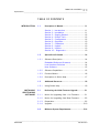


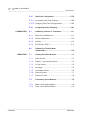


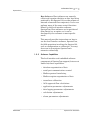
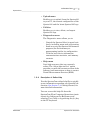
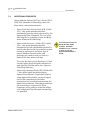
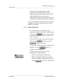


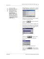
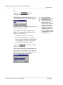
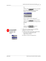
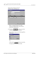
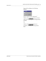

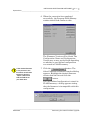
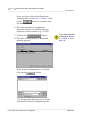

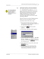


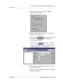

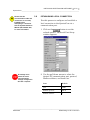

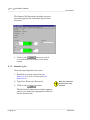
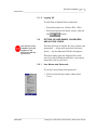
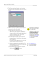


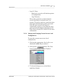
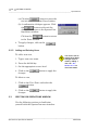


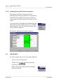


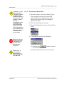

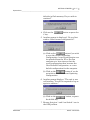
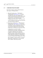

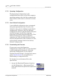
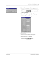
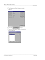


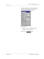
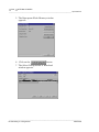
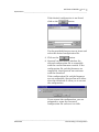


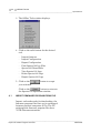
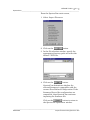


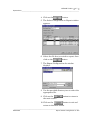
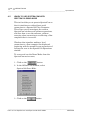
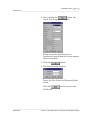
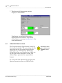

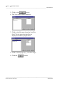


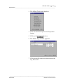


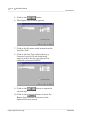
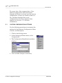


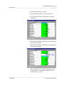
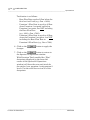

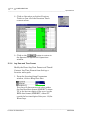
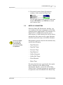
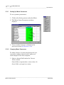
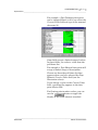
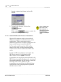
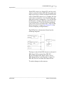
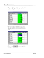
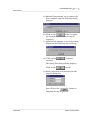

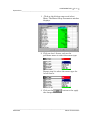

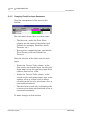
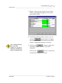
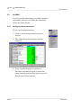


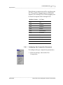
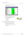
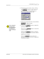


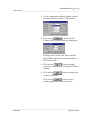
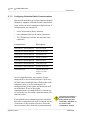
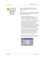

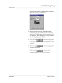


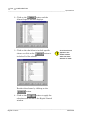


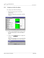
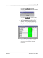
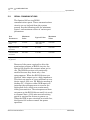


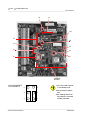
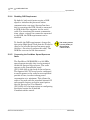
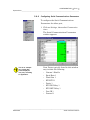
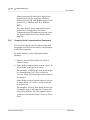
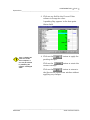
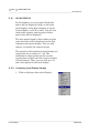
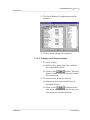

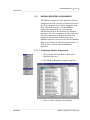
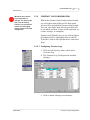

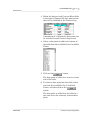
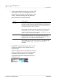
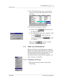
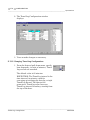
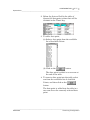
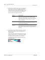
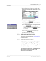
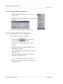
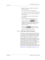
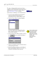
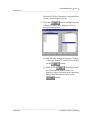


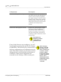
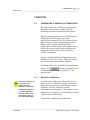

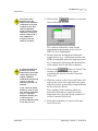


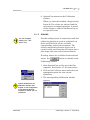


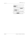


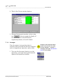

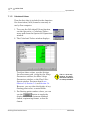

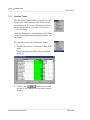
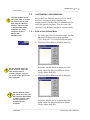


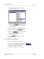
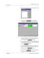


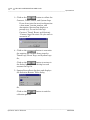
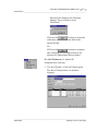
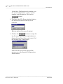
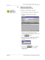
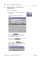

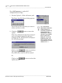

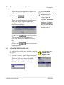
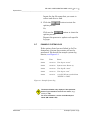

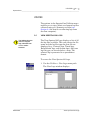

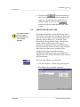

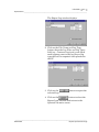

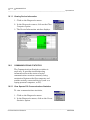
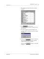

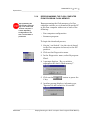
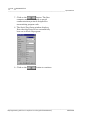
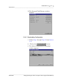
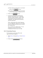
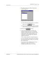
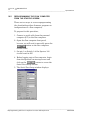
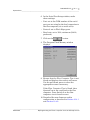


![[U2.03.04] Notice d`utilisation pour des calculs](http://vs1.manualzilla.com/store/data/006355171_1-e4204e3f6eed19ac00fe22b1d72a0ea8-150x150.png)