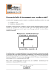
1
DRILL MANAGER
INSTALLATION AND INSTRUCTION
MANUAL
About the Manual
This manual is written in modular form. Only the components specific to your Drill
Manager System are included. Each component of the Drill Manager (modules and
sensors) has a section in the manual. Each section covers the installation, calibration
and operation of the component. Each section, also, includes a troubleshooting section to help ensure faultless operation.
About the Drill Manager
Every component of the Drill Manager is automatically identified; no programming
needed. The modules connect together in series starting with the Power module.
Sensors and adapters can be connected into any of the module mini-DIN inputs.
Input
or
Output
Module Cable
Input
Output
Each module has two Module cable connectors: input and output (excluding the Power
module). These connectors allow the modules to be plugged together by removing
the dust-caps with a Phillips screw driver, and then plugging the input of a module
into the output of another module. A Module cable can also be used to make this
connection (see diagram). Always leave the dust cap on the output of the last module.
mini-DIN Cable
Module Cable
Most modules have two mini-DIN inputs labelled Input A and Input B. Sensors and
adapters are connected into the Drill Manager by removing the dust-plugs from the
sensor and module mini-DIN inputs, and then plugging a mini-DIN cable into the
inputs. When multiples of the same sensor or module are connected, the system
issues them a number by the connection order to allow the operator to identify them.
G:\PRODUCTS\GR99H\FP\MANUAL\fpdm0u05.pdf
Drill Manager User Manual
Page 1-1
Drill Manager
Introduction
About the Drill Manager (continued)
Every module and sensor in the Drill Manager has a built in power light. The power
lights remain off until the Power switch is turned on. When programming a module,
the power light will flash.
The Drill Manager sensors use hall-effect technology. This technology allows the sensors (i.e. Shaft,
Speed and Fan) to detect either magnetic or metal
targets. The type of target determines the distance
that the sensor is from the target. When detecting
RPM from a metal target the operating distance is an 1/8 of an inch.
Power Light
Whereas, with a magnetic target the
Module Input
Module Output
operating distance is 1/2 of an inch.
mini-DIN
mini-DIN
To use a magnet as a target, the mounting location for the magnet
must be clean. Otherwise, the adhesive backing may not secure the
magnet in place. A cable tie can be used to help secure the magnet.
Metal targets can be anything made of ferrous metal such as key
chucks, gear teeth or bolt heads.
All the calibration values and accumulated information is saved in the system memory.
When the system is turned on, any previous information is restored, and the manufacturer software version is shown on the Monitor Head as exampled below:
Fargo Aire
v24
At this time, all the modules and sensors are automatically detected. If a change is
detected in the system configuration, this message will be displayed on the Monitor
Head:
Config. Changed
then
Press Key to ACK
An audible alarm will accompany this message. Pressing any button on the Monitor
Head acknowledges this alarm. Once acknowledged, the SHOW INSTALL menu
from Calibration mode is automatically selected. The SHOW INSTALL menu is used
to confirm that all the sensors and modules have been detected.
To exit the SHOW INSTALL menu, and any other mode or calibration menu, press a
mode button. If this is done while in a menu containing system calibration values, no
changes are made and this message is displayed:
Cancelled
Only one mode can be displayed at a time, but every mode of operation is continually
monitored by the Smart Alarm regardless of which mode is selected. The Smart Alarm
is designed to effectively alert the user of alarm conditions. If an alarm condition
occurs, the Smart Alarm technology prioritizes the detected alarm, and will interrupt
low priority alarms with conditions of higher priority. Every audible alarm is sounded
by the Switch Box.
Page 1-2
Drill Manager User Manual
G:\PRODUCTS\GR99H\FP\MANUAL\fpdm0u05.pdf
MONITOR HEAD
Drill Manager
Table of Contents
About the Manual .................................................................................................................. 1-1
About the Drill Manager ......................................................................................................... 1-1
Warranty ................................................................................................................................ 1-6
Disclaimer .............................................................................................................................. 1-6
About the Monitor Head ......................................................................................................... 1-7
1. Installation ......................................................................................................................... 1-7
2. Calibration ......................................................................................................................... 1-7
3. Operation ........................................................................................................................... 1-7
4. Troubleshooting ............................................................................................................... 1-12
If all else fails ....................................................................................................................... 1-13
SWITCH BOX
About the Switch Box .......................................................................................................... 1-15
1. Installation ....................................................................................................................... 1-15
2. Calibration ....................................................................................................................... 1-15
3. Operation ......................................................................................................................... 1-15
4. Troubleshooting ............................................................................................................... 1-17
POWER MODULE
About the Power Module ..................................................................................................... 1-19
1. Installation ....................................................................................................................... 1-19
2. Calibration ....................................................................................................................... 1-19
3. Operation ......................................................................................................................... 1-19
4. Troubleshooting ............................................................................................................... 1-20
CLUTCH MODULE
About the Clutch Module ....................................................................................................... 2-1
1. Installation ......................................................................................................................... 2-1
2. Calibration ......................................................................................................................... 2-2
3. Operation ........................................................................................................................... 2-2
4. Troubleshooting ................................................................................................................. 2-5
HLYDRAULIC MOTOR DRIVER MODULE
About the Clutch Module ....................................................................................................... 3-1
1. Installation ......................................................................................................................... 3-1
2. Calibration ......................................................................................................................... 3-1
3. Operation ........................................................................................................................... 3-2
4. Troubleshooting ................................................................................................................. 3-6
FLOW MODULE
About the EOH Module ......................................................................................................... 4-1
1. Installation ......................................................................................................................... 4-1
2. Calibration ......................................................................................................................... 4-2
3. Operation ........................................................................................................................... 4-2
4. Troubleshooting ................................................................................................................. 4-5
S IX C HANNEL M ODULE
About the Six Chennel Module ............................................................................................... 5-1
1. Installation .......................................................................................................................... 5-1
2. Calibration .......................................................................................................................... 5-1
3. Operation ............................................................................................................................ 5-1
4. Troubleshooting .................................................................................................................. 5-1
T HREE L OAD M ODULE
About the Three Load Module ................................................................................................ 6-1
1. Installation .......................................................................................................................... 6-1
2. Calibration .......................................................................................................................... 6-2
3. Operation ............................................................................................................................ 6-2
4. Troubleshooting .................................................................................................................. 6-2
BIN SENSOR
About the Six Channel Module ............................................................................................... 7-1
1. Installation .......................................................................................................................... 7-1
2. Calibration .......................................................................................................................... 7-2
3. Operation ............................................................................................................................ 7-2
4. Troubleshooting .................................................................................................................. 7-2
FAN SENSOR
About the Fan Sensor.... ........................................................................................................ 8-1
1. Installation .......................................................................................................................... 8-1
2. Calibration .......................................................................................................................... 8-1
3. Operation ............................................................................................................................ 8-2
4. Troubleshooting .................................................................................................................. 8-2
SHAFT SENSOR
About the Shaft Sensor ........................................................................................................ 9-1
1. Installation ........................................................................................................................ 9-1
2. Calibration ........................................................................................................................ 9-1
3. Operation .......................................................................................................................... 9-2
4. Troubleshooting ................................................................................................................ 9-2
SPEED SENSOR
About the Speed Sensor ...................................................................................................... 10-1
1. Installation ........................................................................................................................ 10-1
2. Calibration ........................................................................................................................ 10-1
3. Operation .......................................................................................................................... 10-2
4. Troubleshooting ................................................................................................................ 10-2
WORK SWITCH SENSOR
About the Work Switch Sensor. ............................................................................................ 11-1
1. Installation ........................................................................................................................ 11-1
2. Calibration ........................................................................................................................ 11-1
3. Operation .......................................................................................................................... 11-2
4. Troubleshooting ................................................................................................................ 11-2
APPENDICES
Appendix A: Conversion Table ............................................................................................. 1-21
Appendix B: Calibration Record Sheet ................................................................................. 1-21
Appendix D: Smart Alarm Logic ........................................................................................... 1-23
Appendix E: Sensor Cable Color Code ................................................................................ 1-29
Drill Manager
Table of Contents
Warranty
Once Agtron Enterprises Inc. receives a completed warranty card, the Fargo Products Drill Manager is covered by a three year warranty on materials and workmanship. Without a completed warranty card, the Drill Manager is covered for only one
year. Any warranty shipping costs and installation labour are the responsibility of the
customer. Damage due to customer error, unauthorized modifications, installation
error, electrical system failure, fire, thief, or natural disaster is not covered by warranty.
If unsatisfied with the Fargo Products Drill Manager, a full refund is offered. To receive the refund, contact Agtron Enterprises Inc. and return all the purchased parts
(in good condition) within 30 days of the date of purchase. There may be charges for
missing, damaged or unrecoverable components.
There are no customer serviceable parts inside the Monitor Head and Switch Box. If
the security screw is removed, warranty will be void.
Disclaimer
Agtron Enterprises Inc. takes no responsibility for injuries, damages, or losses due to
the use, misuse, abuse, or failure of this equipment. It is the responsibility of the
customer to understand the operation of the Fargo Products Drill Manager to ensure
that the equipment is operating properly.
All products produced by Agtron Enterprises Inc. are intended for use with agricultural implements. Any other application has not been considered, therefore complying with building, or safety regulations is the sole responsibility of the customer.
Page 1-6
Drill Manager User Manual
G:\PRODUCTS\GR99H\FP\MANUAL\fpdm0u05.pdf
Drill Manager
Monitor Head
MONITOR HEAD
About the Monitor Head
The main function of the Monitor Head is to display the Drill
Manager system information such as fan RPM, ground speed
and metering shaft RPM. Other functions include entering calibration values and changing Drill Manager options.
1. Installation
Before installing the Monitor Head, install the Power module and Switch Box. Included
below are the mounting and connection procedures needed to install the Monitor Head. No
tools are required to install the Monitor Head.
1.1. Mounting
Select a mounting location where the Monitor Head can be easily seen and all the
buttons are readily accessible. Remove the backing of the adhesive Velcro® strip
located on the back of the Monitor Head, and secure it to the mounting location.
1.2. Connections
Plug the mini-DIN cable from the Switch Box into the mini-DIN input on the bottom of
the Monitor Head (see diagram).
Fargo Product Monitor Head
Fargo Products Switch Box
mini-DIN Cable
1.3. SHOW INSTALL ?
Enter the SHOW INSTALL menu, and use the Plus and Minus buttons to locate this
message:
1 Monitor Head
The Monitor Head has now been successfully installed.
2. Calibration
No calibration is required for the Monitor Head.
3. Operation
There are 10 modes of operation: Bin, Shaft, Speed, Fan, Tram, Variable Rate, Area,
Flow, Calibration and Advanced Calibration. To select a mode of operation, press the
desired mode button (see diagram). Once selected, a light above the mode button turns
on.
G:\PRODUCTS\GR99H\FP\MANUAL\fpdm0u05.pdf
Drill Manager User Manual
Page 1-7
Drill Manager
Monitor Head
3. Operation (continued)
Below is a list of the modes of operation available on the Drill Manager. Each description
refers to the sensors or modules needed for the modes of operation to function.
**For more information, see the mentioned module or sensor manual.**
In extreme emergencies, a hidden menu can be used to restore the calibration values in
both the Calibration and Advanced Calibration modes back to the factory presets. To enter
the hidden menu, press the Plus, Minus and Calibration buttons simultaneously. When
selected, this message is displayed:
DEFAULT CAL# ?
Press the OK button to restore the factory presets. Doing so will copy over any changes to
the calibration values.
Fan mode
Speed mode
Plus
Shaft mode
Calibration mode
Bin mode
Indicator Light
Display
Tram mode
Ok
Variable Rate mode
Minus
Area mode
Flow mode
3.1. Bin Mode
Bin sensors are required for this mode to operate. For more information, see the Bin
Sensor section of this manual. Without Bin sensors, this message is displayed:
NO BINS FOUND
3.2. Shaft Mode
Shaft sensors or variable rate devices are required for this mode to operate. For more
information, see the Shaft Sensor, or Electric Motor Driver Module sections of this
manual. Without Shaft sensors or variable rate devices, this message is displayed:
NO SHAFTS FOUND
3.3. Speed Mode
A Speed sensor or Radar adapter is required for this mode to operate. For more
information, see the Speed Sensor, or Radar Adapter sections of this manual. Without a Speed sensor or Radar adapter, the Monitor Head creates a fake “test” speed,
and will periodically display:
Test Speed On
Page 1-8
Drill Manager User Manual
G:\PRODUCTS\GR99H\FP\MANUAL\fpdm0u05.pdf
Drill Manager
Monitor Head
3. Operation (continued)
3.4. Fan Mode
Fan sensors are required for this mode to operate. For more information, see the Fan
Sensor section of this manual. Without Fan sensors, this message is displayed:
NO FANS FOUND
3.5. Tram Mode
A Tram module is required for this mode to operate. For more information, see the
Tram Module section of this manual. Without a Tram module, this message is displayed:
NO Tram Module
3.6. Variable Rate Mode
Variable rate devices are required for this mode to operate. For more information, see
the Electric Motor Driver Module, Liquid Module, or Shaft Sensor sections of this
manual. Without a variable rate device, this message is displayed:
NO Devices FOUND
3.7. Area Mode
A Speed sensor, Radar adapter or variable rate device is required for this mode to
operate. For more information, see the Speed Sensor, Radar Adapter, Electric Motor
Driver Module, Liquid Module, or Shaft Sensor sections of this manual. Without a
Speed sensor, or variable rate device, the Monitor Head will display the FIELD and
TOTAL counters, but they are inactive.
3.8. Flow Mode
A Flow module is required for this mode to operate. For more information, see the
Flow Module section of this manual. Without a Flow module, this message is displayed:
NO FLOW MODULE
3.9. Calibration Mode
There are up to six calibration menus located in Calibration mode. To scroll through
the menu options, use the Plus and Minus buttons. When the desired menu option is
displayed, press the OK button to enter the menu. Listed below are the menu options
located in the Calibration mode. Certain calibration menus are not displayed if the
related device is not connected.
3.9.1. SHOW INSTALL ?
This menu option allows the user to view the connected modules and sensors.
Only one component is displayed at a time. Use the Plus and Minus buttons to
view all the installed components. After the last connected component is shown,
this message is displayed:
-- END -G:\PRODUCTS\GR99H\FP\MANUAL\fpdm0u05.pdf
Drill Manager User Manual
Page 1-9
Drill Manager
Monitor Head
3. Operation (continued)
3.9. Calibration Mode (continued)
3.9.2. DISTANCE CHECK ?
This menu option is only available with a Speed sensor. For more information,
see the Speed Sensor, or Radar Adapter sections of this manual.
3.9.3. VR CALIBRATION ?
This menu option is only available with variable rate devices. For more information, see the Electric Motor Driver Module, Liquid Module, or Shaft Sensor sections of this manual.
3.9.4. SEED CHECK ?
This menu option is only available with variable rate devices. For more information, see the Electric Motor Driver Module, or Shaft Sensor sections of this manual.
3.9.5. GPS ?
This menu option is only available with an RS-232 module. For more information, see the RS-232 Module section of this manual.
3.9.6. DELTA STEP ?
This menu option is only available with variable rate devices. For more information, see the Electric Motor Driver Module, or Liquid Module sections of this
manual.
3.10. Advanced Calibration Mode
To enter the Advanced Calibration mode, press and hold the Calibration button until
this message is displayed:
Smart Alarm ?
Use the Plus and Minus buttons to scroll through the menu options. To enter a menu
option, press the OK button. Listed below are all the menu options located in the
Advanced Calibration mode. Certain calibration menus are not displayed if the related device is not connected.
3.10.1. SMART ALARM ?
This menu is used to activate or deactivate the SMART ALARM feature. If the
SMART ALARM is set to OFF, the system will not notify the operator of any
alarms conditions. When selected this message is displayed:
SMART ALARM ON
Use the Plus and Minus buttons to switch between ON or OFF. Once the selection has been made, press the OK button to complete the change.
3.10.2. BACK LIGHT ?
This menu is used to activate or deactivate the Monitor Head back light. When
selected this message is displayed:
BACK LIGHT ON
Page 1-10
Drill Manager User Manual
G:\PRODUCTS\GR99H\FP\MANUAL\fpdm0u05.pdf
Drill Manager
Monitor Head
3. Operation (continued)
3.10. Advanced Calibration Mode (continued)
Use the Plus and Minus buttons to switch between ON or OFF. As the options
change, the back light will turn on and off respectively. Once the selection has
been made, press the OK button to complete the change.
3.10.3. SHAFT LOW ?
This menu option is only available with Shaft sensors. For more information,
see the Shaft Sensor section of this manual.
3.10.4. SHAFT TARGS/REV?
This menu option is only available with Shaft sensors. For more information,
see the Shaft Sensor section of this manual.
3.10.5. CIRCUMFERENCE ?
This menu option is only available with a Speed sensor or Radar adapter. For
more information, see the Speed Sensor, or Radar Adapter sections of this
manual.
3.10.6. WIDTH ?
This menu option is used to set the width of the air seeder in inches or millimeters. This calibration value is needed to calculate the area coverage. When
selected, this message is displayed:
WIDTH
672.0 IN
Use the Plus and Minus buttons to change the displayed value to the actual
width of the air seeder. Once the width has been set, press the OK button to
complete the change.
3.10.7. FAN LOW ?
This menu option is only available with Fan sensors. For more information, see
the Fan Sensor section of this manual.
3.10.8. FAN HIGH ?
This menu option is only available with Fan sensors. For more information, see
the Fan Sensor section of this manual.
3.10.9. FAN TARGETS/REV?
This menu option is only available with Fan sensors. For more information, see
the Fan Sensor section of this manual.
3.10.10. TOTAL SEED ROWS?
This menu option is only available with a Tram module. For more information,
see the Tram Module section of this manual.
3.10.11. TRAM ROWS-CH1 ? and TRAM ROWS-CH2 ?
These menu options are only available with a Tram module. For more information, see the Tram Module section of this manual.
G:\PRODUCTS\GR99H\FP\MANUAL\fpdm0u05.pdf
Drill Manager User Manual
Page 1-11
Drill Manager
Monitor Head
3. Operation (continued)
3.10. Advanced Calibration Mode (continued)
3.10.12. TRAM RHYTHM ?
This menu option is only available with a Tram module. For more information,
see the Tram Module section of this manual.
3.10.13. UNITS ?
This menu option is used to change the system of measurement (imperial or
metric). When selected, this message is displayed:
UNITS
AMERICAN
Use the Plus and Minus buttons to switch between American (imperial) and
metric. Once the selection has been made, press the OK button to complete the
change. All the calibration values and counters will be automatically converted.
Listed below is a table of the various units of measurement used by the Drill
Manager.
Modes
Bin mode
Tram mode
Shaft mode
Variable Rate mode
Speed mode
Area mode
Fan mode
Flow mode
Metric
n/a
n/a
revolutions per minute
kilograms per hectare, litres per hectare
kilometers per hour, litres per hectare,
kilograms per hectare
hectares, kilograms, litres
revolutions per minute
n/a
Imperial
n/a
n/a
revolutions per minute
pounds per acre, gallons per acre
miles per hour, gallons per acre,
pounds per acre
acres, pounds, gallons
revolutions per minute
n/a
3.10.14. LANGUAGE ?
This menu option is used to change the displayed language. When selected,
this message is displayed:
ENGLISH
Use the Plus and Minus buttons to scroll through the various languages (English, German, French, Tschech, Polish, Spanish, Hungarian and Danish). Once
the desired language has been selected, press the OK button to complete the
change.
3.10.15. SYSTEM CONSTANT?
This menu option is only available with a Liquid module. For more information,
see the Liquid Module section of this manual.
3.10.16. VR # 1 CAL ? to VR # 5 CAL ?
These menu options are only available with variable rate devices. For more
information, see the Electric Motor Driver Module, Liquid Module, or Shaft Sensor sections of this manual.
Page 1-12
Drill Manager User Manual
G:\PRODUCTS\GR99H\FP\MANUAL\fpdm0u05.pdf
Drill Manager
Monitor Head
3. Operation (continued)
3.10. Advanced Calibration Mode (continued)
3.10.17. SAVE CAL?
This menu option is only available with variable rate devices. For more information, see the Electric Motor Driver Module, Liquid Module, or Shaft Sensor sections of this manual.
3.10.18. READ CAL?
This menu option is only available with variable rate devices. For more information, see the Electric Motor Driver Module, Liquid Module, or Shaft Sensor sections of this manual.
3.10.19. WORK
This menu option is only available with a Work Switch sensor or adapter. For
more information, see the Work Switch Sensor, or Work Switch Adapter sections of this manual.
4. Troubleshooting
Listed below are situations that could occur. Follow the SOLUTION process to restore
normal operation.
SITUATION
The Monitor Head does not power-up. The Power module’s power light lights-up, but
the Monitor Head display remains blank.
SOLUTION
First, check that the Monitor Head and the Switch Box are connected as described in
the Installation section.
Second, replace the cable connecting the Monitor Head and the Switch Box.
Third, replace the Monitor Head.
SITUATION
The Monitor Head displays COMM ERROR DISP when the system is turned on.
SOLUTION
First, check that the Monitor Head and the Switch Box are connected as described in
the Installation section.
Second, replace the cable connecting the Monitor Head and the Switch Box.
Third, replace the Monitor Head.
SITUATION
When the Power switch is turned on, the Monitor Head only displays the manufactures names and the software version (i.e. AGTRON
v23)
G:\PRODUCTS\GR99H\FP\MANUAL\fpdm0u05.pdf
Drill Manager User Manual
Page 1-13
Drill Manager
Monitor Head
4. Troubleshooting (continued)
SOLUTION
First, check that the Power module is connected directly to the tractor battery.
Second, check the voltage of the tractor battery. If the battery is almost drained, this
situation will occur.
Third, replace the cable between the Switch Box and Monitor Head.
Fourth, replace the cable between the Switch Box and Power module.
If all else fails... Reread the manual section, making note of any questions, and
contact Agtron Enterprises Inc. at:
AGTRON ENTERPRISES INC.
242 Robin Crescent
Saskatoon, Saskatchewan, Canada S7L 7C2
Phone 800-667-0640
306-934-0640
Fax
306-668-7666
email
[email protected]
www.agtron.com
Page 1-14
Drill Manager User Manual
G:\PRODUCTS\GR99H\FP\MANUAL\fpdm0u05.pdf
Drill Manager
Switch Box
SWITCH BOX
About the Switch Box
The Switch Box provides the operator control of the connected
modules. The Switch Box is also used to turn the Drill Manager
system on and off, and generate the audible alarms.
1. Installation
Before installing the Switch Box, install the Power module. Included below are the mounting
and connection procedures needed to install the Switch Box. No tools are required to
install the Switch Box.
1.1. Mounting
Select a convenient mounting location where all the switches are readily accessible.
Remove the backing of the adhesive Velcro® strip located on the back of the Switch
Box, and secure it to the mounting location.
1.2. Connections
Plug the mini-DIN cable from the Power module into the right mini-DIN input on the
bottom of the Switch Box (see diagram). Plug a mini-DIN cable into the left mini-DIN
input, and run the mini-DIN cable to the desired mounting location for the Monitor
Head.
Fargo Products Switch Box
Power Module
mini-DIN Cable
1.3. SHOW INSTALL ?
Enter the SHOW INSTALL menu, and use the Plus and Minus buttons to locate this
message:
1 Switch Box
The Switch Box has now been successfully installed.
2. Calibration
No calibration is required.
3. Operation
The Switch Box has six switches: a Power switch, 4 Control switches, and one Master
switch. Listed below is a description of each switch. Some descriptions refer to modules
needed for the switch to function. For further information, see the module section.
G:\PRODUCTS\GR99H\FP\MANUAL\fpdm0u05.pdf
Drill Manager User Manual
Page 1-15
Drill Manager
Switch Box
3. Operation (continued)
Control Switches
Power Switch
Master Switch
3.1. Power Switch
When the Power switch is turned on, power is supplied to the entire Drill Manager
system. When this happens, the light above the Power switch turns on.
3.2. Master Switch
This switch is the main control or work switch for the system. When seeding, the
Master switch must be turned on. The light above the Master switch lights-up when
the switch is on. With the Master switch turned off, variable rate devices are deactivated, the Area mode counters do not accumulate, and the Smart Alarm is disabled.
Note: With the Master switch turned off, devices connected to Clutch or 3Load
modules can still be controlled.
3.3. Control Switches
Control switches are assigned to
Electric Motor
modules in the order that the
Clutch Module
Clutch Module
Driver Module
modules are connected. For example, a Drill Manager with a
Clutch module connected to the
Power module, a second Clutch module connected to the first, and an Electric Motor
Driver module connected to the second Clutch module. Control switch 1 would be
assigned to the first Clutch and the Electric Motor Driver module, and Control switch
2 would be assigned to the second Clutch module. Listed below are the various ways
the Control switches are used.
3.3.1. Clutch and/or 3Load Modules
When Clutch and 3Load modules are connected, the Control switches can be
used to control electric devices. To activate a device, click the appropriate Control switch up.
Once activated, the light above the Control switch will turn on. To deactivate a
device, click the Control switch down. The light above the Control switch will turn
off.
Page 1-16
Drill Manager User Manual
G:\PRODUCTS\GR99H\FP\MANUAL\fpdm0u05.pdf
Drill Manager
Switch Box
3. Operation (continued)
3.3.2. Variable Rate Devices
When variable rate devices are connected, the Control switches can be used to
adjust an application rate by a preset amount. To increase an application rate,
click the appropriate Control switch up. To decrease an application rate, click
the appropriate Control switch down.
After an application rate has been adjusted, the light above the Control switch
flashes until the original application rate is restored.
Note: Variable rate devices work only when the Master switch is turned on.
3.3.3. Both
When Clutch and/or 3Load modules, and variable rate devices are connected,
the process of adjusting an application rate stays the same, but the process of
controlling an electric device changes. To activate an electric device when the
Master switch is turned on, hold the appropriate Control switch in the up position
for about three seconds. To deactivate an electric device when the Master switch
is turned on, hold the appropriate Control switch in the down position for about
three seconds. If the Master switch is turned off, the variable rate devices are
turned off, and the Clutch and 3Load modules are controlled normally.
4. Troubleshooting
Listed below are situations that could occur. Follow the SOLUTION process to restore
normal operation.
SITUATION
When the power switch is turned on, the power lights remain off and the Monitor Head
display remains blank.
SOLUTION
First, check that there is power to the Power module (power light). The tractor battery
should be supplying over 12 volts.
Second, ensure that the cable between the Power module and the Switch Box is
connected as described in the Installation section.
Third, replace the cable connecting the Power module and the Switch Box.
Fourth, replace the Switch Box.
G:\PRODUCTS\GR99H\FP\MANUAL\fpdm0u05.pdf
Drill Manager User Manual
Page 1-17
Drill Manager
Switch Box
Page 1-18
Drill Manager User Manual
G:\PRODUCTS\GR99H\FP\MANUAL\fpdm0u05.pdf
Drill Manager
Power Module
POWER MODULE
About the Power Module
The Power module sources power for the Drill Manager system and electronically limits the current so that fuses are unnecessary. The Power module also connects the Monitor Head
and Switch Box to the rest of the connected modules.
1. Installation
The Power module should be the first module installed. Included below is a list of tools,
mounting and connection procedures needed to install the Power module.
1.1. Tools
The tools needed to install the Power module are:
· 5/16” hex-driver or socket
· 1/8” drill bit
· drill
1.2. Mounting
Select a mounting location close to the tractor battery. To avoid damage to the Power
module, ensure that the mounting location is free of moving parts and material passing under the tractor. Secure the Power module to the mounting location with self
tapping screws (supplied) using a 5/16” hex-driver or socket. Drilling a 1/8” pilot hole
will make installation easier.
1.3. Connections
Connect the red wire of the Power module to the positive terminal of the tractor battery, and the black wire to the negative terminal of the tractor battery.
Plug a Module cable into the output terminal of the Power module. Run the Module
cable to the tractor hitch. Plug a mini-DIN cable into the Switch Box mini-DIN input of
the Power module. Run the mini-DIN cable into the tractor cab. This cable will be
plugged into the Switch Box.
1.4. SHOW INSTALL ?
The Power module is not shown in the SHOW INSTALL ? menu.
2. Calibration
No calibration is required.
3. Operation
No operating instructions required.
G:\PRODUCTS\GR99H\FP\MANUAL\fpdm0u05.pdf
Drill Manager User Manual
Page 1-19
Drill Manager
Power Module
4. Troubleshooting
Listed below are situations that could occur. Follow the SOLUTION process to restore
normal operation.
SITUATION
The power lights remain off and the Monitor Head display remains blank.
SOLUTION
First, check that there is power to the Power module (power light). The tractor battery
should be supplying above 12 volts.
Second, check that the cable between the Power module and the Switch Box is
connected as described in the Installation section.
Third, replace the cable connecting the Power module and the Switch Box.
Fourth, replace the Power module.
Page 1-20
Drill Manager User Manual
G:\PRODUCTS\GR99H\FP\MANUAL\fpdm0u05.pdf
Drill Manager
Clutch Module
CLUTCH MODULE
About the Clutch Module
Clutch modules provide the Drill Manager System with control
over electric devices. Four Clutch modules can be installed on
a Drill Manager. If a 3Load module is installed, only one Clutch
module can be installed. Clutch modules have two mini-DIN
inputs for installing additional sensors.
1. Installation
Before installing a Clutch module, install the Monitor Head, Switch Box and Power module.
Included below is a list of tools, mounting and connection procedures needed to install a
Clutch module.
1.1. Tools
The tools needed to install the Clutch module are:
· 5/16” hex-driver or socket
· drill
· 1/8” drill bit
· wire cutters
1.2. Mounting
Select a mounting location that is close to the electric device. Secure the Clutch module
to the mounting location with self tapping screws (supplied) using a 5/16” hex-driver
or socket. Drilling a 1/8” pilot hole will make installation easier.
1.3. Connections
Run the Clutch module cable to the electric device. Cut the Clutch module cable to
a convenient length. There are two wires in the cable. The white wire is a positive or
a hot wire, and the black wire is a negative or a common wire. Connect the cable to
the electric device.
1.4. SHOW INSTALL ?
Enter the SHOW INSTALL menu, and use the Increment and Decrement buttons to
locate this message:
# Clutch
Where # is the number of Clutch modules installed. The Clutch module has been
successfully installed.
2. Calibration
No calibration is required.
3. Operation
For normal operation, the Calibrate switch if installed must be in the Operate position. When
the switch is in the Calibrate position, the electric device will activate, and the Control switch
no longer controls the device. The electric device will remain active until the Calibrate switch
is set to Operate. This is used as a manual override.
2-1
Drill Manager
Clutch Module
4. Troubleshooting
Listed below are situations that could occur. Follow the SOLUTION process to restore
normal operation.
SITUATION
The Clutch module is not displayed in the SHOW INSTALL ? menu.
SOLUTION
First, check that the module is connected as described in the Installation section.
Second, check that there is power to the module (power light).
Third, connect the Clutch module into another module.
Fourth, replace the Module cable.
Fifth, replace the Clutch module.
SITUATION
The Monitor Head displays COMM ERROR CPM 1 when the Clutch module is connected.
SOLUTION
First, check that the module is connected as described in the Installation section.
Second, connect the Clutch module into another module.
Third, replace the Module cable.
Fourth, replace the Clutch module.
SITUATION
The Clutch module is displayed in the SHOW INSTALL menu, but the Control switch
does not activate the electric device.
SOLUTION
First, check that there is power to the module (power light).
Second, check that the correct Control switch is being used.
Third, check that the electric device is connected as described in the Installation
section. If the wires of the Clutch cable are reversed, the device will not activate.
Fourth, replace the Clutch module.
SITUATION
The Monitor Head displays > 5 CLUTCHES.
SOLUTION
First, check no more than five Clutch modules are connected.
Second, disconnect every Clutch module, and check the SHOW INSTALL menu.
No Clutch module should be shown. If a Clutch module is shown, disconnect all the
modules and skip to the Fourth step.
Third, connect one Clutch module and turn on the system. Check that the listed items
in the SHOW INSTALL menu are correct. If the problem reoccurs, replace the Clutch
module. Repeat this process for every Clutch module.
Fourth, connect one module and turn on the system. Check that the listed items in
the SHOW INSTALL menu are correct. Repeat this process until the failure reoccurs,
and replace the defective module.
2-2
Drill Manager
Clutch Module
SITUATION
Clutch will not turn off.
SOLUTION
First, check that switch (if installed) is in the operate position.
Second, check that sprocket on clutch turns freely with monitor shut off. If not, remove
bolt from end of clutch shaft, remove and clean sprocket bushing.
2-3
Drill Manager
Hydraulic Motor Driver Module
HYDRAULIC MOTOR DRIVER MODULE
About the EOH (Electric over hydraulic)
Module
Hydraulic Motor Driver (EOH) modules are a type of variable rate
device available with the Drill Manager System. EOH modules
provide control over variable rate hydraulic motors. Five variable
create devices can be installed. Each EOH module also has two
mini-DIN inputs for connecting additional sensors.
1. Installation (Aftermarket units only)
Before installing the EOH module, install the monitor Head, Switch Box and Power module.
Included below is a list of tools, mounting and connection procedures needed to install an
EOH.
1.1. Tools
The tools needed to install the EOH module are:
· 5/16” hex-driver or socket
· drill
· 1/8” drill bit
· wire cutters
1.2. Mounting
Select a flat metal mounting location within three feet of the hydraulic motor. Remove
any dirt or grease from the flat mounting surface. A clean, flat surface is needed to
dissipate heat through the metal plate. Using a 5/16” hex-driver and the provided
self tapping screws, secure the module to the mounting location. Drilling a 1/8” pilot
hole will make installation easier.
1.3. Connections
Connect a module cable
Route the module cable to the PWM valve and tach sensor. Plug the two wire lead
into the PWM valve and the three wire lead into the tach sensor. Using cable ties,
secure the cable to the equipment chassis.
1.4. SHOW INSTALL ?
Enter the SHOW INSTALL menu, and use the Plus and Minus buttons to locate this
message:
# VR EOH
Where # is the number of installed EOH modules. If this message is displayed, the
EOH module has been successfully installed.
2. Calibration
There are six calibration menus for the EOH module, but not every menu is required. Only
the menu needed for immediate operation is described below. For any other menus, see
the Operation section.
3-1
Drill Manager
Hydraulic Motor Driver Module
2.1. VR CALIBRATION?
This menu is used to set the application rate, determine the weight output per revolution
of the meter, and calculate the ground speed limit. When selected, this message is
displayed:
PRODUCT #1
The PRODUCT label is given the same number as the EOH module associated with
it. With multiple EOH modules, use the Plus and Minus buttons to select the desired
PRODUCT label. Press the OK button to make the selection, and this message is
displayed:
ENTER SEED RATE then RATE# .0.LB/AC
Where # is the number of the selected EOH module. Use the Plus and Minus buttons to
set the application rate in pounds per acre or kilograms per hectare, and press the OK
button to complete the change. This message is displayed:
TURN OUT PRODUCT then ROTATIONS 0.0
Activate the fan hydralic circuit and shut off ball valve at the fan. Get a receptacle to
collect the product from the metering box. Set the Calibrate switch on the EOH module to
Calibrate.
The motor will begin turning the metering shaft. As the meter turns, the
number beside ROTATIONS will accumulate in tenths of a rotation. Once a sample has
been collected, switch the Calibrate switch to Operate to stop the motor. This message is
displayed:
WEIGHT O G
Weigh the product and record the weight.
NOTE: MAKE SURE TO READ THE KILOGRAM SIDE OF The SCALE AND MU LIT I PLY
BY 1000 TO OBTAIN THE NUMBER OF GRAMS. FOR EXAMPLE 4.6 ON THE SCALE
IS 4600 GRAMS.
Use the Plus and Minus buttons to set the product weight, and press the OK button to
complete the change. This message is displayed:
SPEED RANGE then #.#min - #.#max MPH
Where #.#min is the minimum speed, and #.#max is the maximum speed needed to
provide the set application rate. The application rate, product weight and speed range has
now been set.
3. Operation
For the EOH module to function, the Calibrate switch must be in the Operate position.
When the switch is in the Calibrate position, the hydraulic motor will activate, an audible
alarm will sound, and this message is displayed:
CAL SWITCH # ON!
3-2
Drill Manager
Hydraulic Motor Driver Module
Where # is the number of EOH module. The meter motor remains active, and the alarm
continues until the Calibrate switch is set to Operate. The switch is used as a manual
override.
Variable Rate mode is used to view the operation of the EOH modules. With an EOH
module installed, various modes and menus are changed. Listed below are the operating
instructions.
3.1. Variable Rate Mode
This mode is used to display the actual and set application rates of the EOH modules.
When selected, this message is displayed:
R 1 ### LB/AC 0.0
Where ### is the set application rate of the first EOH module (R1). When the Master switch
is turned on , the actual application rate is displayed in the 0.0 position. Use the Variable
Rate mode button to scroll through multiple EOH modules. The Plus and Minus buttons
can be used to change the set application rate.
The EOH module will not operate until the VR CALIBRATION is complete. If the
calibration procedure was not done, this message is displayed when Variable Rate mode
is selected:
CAL REQUIRED
3.2. Speed Mode
Selection Speed mode, in addition to displaying the ground speed, also displays the
application rate of the first variable rate device. When Speed mode is selected, this
message is displayed:
0.0 MPH- 1 0.0
Where 1 is the first variable rate device, and 0.0. is current application rate (in pounds per
acre or kilograms per hectare). When using multiple variable rate devices, use the Plus
and Minus buttons to scroll through the application rates. When scrolling through, the
number will change from 1 to 5.
A speed range is calculated from the application rate, and the physical limits of the motor.
If at the current speed the motor attached to the first EOH module was unable to turn slow
enough to supply the set application rate, this message is displayed:
SPEED TO SLOW!! and PRESS KEY TO ACK
Likewise, if at the current speed the motor attached to the first EOH module was unable to
turn fast enough to supply the set application rate, this message is displayed:
SPEED TO FAST!! and PRESS KEY TO ACK
An audible alarm will accompany these messages. Press any button on the
Monitor Head to acknowledge the alarm condition, and adjust the ground
3-3
Drill Manager
Hydraulic Motor Driver Module
speed accordingly.
3.3. Area Mode
Selecting Area mode displays an applied product weight total for the installed EOH modules.
These counters are labeled PROD, and each is given the same number as the EOH module
associated with it. Use the Plus and Minus buttons to scroll through the product counters.
The product weight is displayed as shown:
PRODUCT 1
___ LBS
Each product counter can be reset to zero. To reset a counter to zero, press and hold the
OK button for about five seconds. This message will be displayed:
CLEAR WEIGHT - # ?
Where # is the number of the selected product counter. Press the OK button to complete
the reset of the counter.
3.4. Shaft Mode
Selecting Shaft mode displays the RPM of the variable rate motors. The variable rate motors
are labeled MOTOR, and each is given the same number as the EOH module associated
with it. The Plus and Minus buttons are used to scroll through the motors. The variable
rate motor RPM is displayed as shown:
MOTOR 1 ___
The system calculates an RPM range. If the motor RPM is slower than what is required
to supply the correct application rate, this message is displayed:
MOTOR SPEED SLOW -# and PRESS KEY TO ACK
If the motor RPM is faster than what is required to supply the correct application rate, this
message is displayed:
MOTOR SPEED HIGH!! and PRESS KEY TO ACK
Where # is the number of the EOH module. An audible alarm accompanies these
messages.
3.5. Seed Check
This Menu is used to calibrate the amount of product weight put out for each turn of the
motor.
PRODUCT # 1
The PRODUCT label is given the same number as the EOH module associated with it.
Use the Plus and Minus buttons to select the EOH module. Once selected, press the OK
button, and this message is displayed:
TURN OUT PRODUCT then WEIGHT
3-4
0G
Drill Manager
Hydraulic Motor Driver Module
Get a receptacle to collect the product from the metering shaft. As the meter turns, the
number beside WEIGHT will increase. Once a sample has been collected, switch the
Calibrate switch to Operate to stop the motor. Weigh the product and record the weight.
Note: The weight measurement is always in grams. If needed, see the
conversion table.
Use the Plus and Minus buttons to set the product weight, and press the OK button to
complete the change. This message will be displayed:
SPEED RANGE then #.# min - #.# max MPH
Where #.# min is the minimum speed, and #.# max is the maximum speed needed to
provide the set application rate. The product weight value per meter turn is now set.
3.6. DELTA STEP ?
This menu sets the amount of application rate change generated by each “one touch”
adjustment of the Control switches. When selected, this message is displayed:
DELTA STEP # 1
The DELTA STEP label is given the same number as the EOH module associated with it.
Use the Plus and Minus buttons to select an EOH module. Press the OK button, and this
message is displayed:
SIZE 10%
The SIZE value is in a percentage (range of 0 to 100). Use the Plus and Minus buttons to
set the SIZE value, and press the OK button to complete the change.
To make a change in rate of the delta step size, push the toggle switch for the product you
want to change up or down to change the rate by the size of the delta step. For example,
if the delta step is 10%, pushing the switch 1 up will increase product 1 by 10%. The light
on the number 1 switch will flash to provide a reminder that you have moved from your
desired rate. Touching the switch down will return you to the target rate and the light will
stop flashing.
3.7. VR #1 CAL? to VR #5 CAL?
This menu is used to display the grams per rotation value of the EOH modules. The VR
label represents the EOH modules. Once selected, this message is displayed:
CAL# 1 ___-__ G/R
Use the Plus and Minus buttons to change the CAL# value, and press the OK button to
complete the change.
3.8. SAVE CAL?
This menu is used to store the EOH module calibration values in memory. Once selected,
this message is displayed:
3-5
Drill Manager
Hydraulic Motor Driver Module
VR # 1 CAL?
The VR labels represent the EOH modules. Use the Plus and Minus buttons to select an
EOH module. Press the OK button, and this message is displayed:
PRODUCT # 1
Use the Plus and Minus buttons to select one of the five PRODUCT labels to save the
EOH module calibration values in, and press the OK button. The values have now been
saved to memory.
3.9. READ CAL?
This menu is used to load the EOH module calibration values from memory. Once selected,
this message is displayed:
PRODUCT # 1
Use the Plus and Minus buttons to select the PRODUCT label containing the saved
calibration values. Once selected, press the OK button, and this message is displayed:
VR # 1 CAL
The VR label represents the EOH modules. Use the Plus and Minus buttons to select the
desired EOH module, and press the OK button. The saved variable rate calibration values
have now been loaded into the selected EOH module.
4. Troubleshooting
Listed below are situations that could occur. Follow the SOLUTION process to restore
normal operation.
SITUATION
The EOH module is not displayed in the SHOW INSTALL ? menu.
SOLUTION
First, check that the module is connected as described in the Installation section.
Second, check that there is power to the module (power light).
Third, connect the EOH module into another module.
Fourth, replace the Module cable.
Fifth, replace the EOH module.
SITUATION
The Monitor Head displays COMM ERROR CPM 1 when the EOH module is connected.
SOLUTION
First, check that the module is connected as described in the Installation section.
Second, connect the EOH module into another module.
Third, replace the Module cable.
Fourth, replace the EOH module.
3-6
Drill Manager
Hydraulic Motor Driver Module
SITUATION
The EOH module is displayed, but the hydraulic motors never turn.
SOLUTION
First, check that the motor is connected as described in the Installation section.
Second, Check that the speed sensor and EOH module calibration procedures have
been done.
Third, check for any error messages (i.e.CAL SWITCH ON -1).
Fourth, replace the EOH module.
SITUATION
When calibrating, motor revolutions aren’t recorded.
SOLUTION
First, check wiring to tachometer sensor
Second, replace tachometer sensor.
SITUATION
Monitor shows motor slow but meter is turning at high rpm.
SOLUTION
First, check wiring to tachometer sensor.
Second, replace tachometer sensor.
3-7
Drill Manager
Flow Module
FLOW MODULE (ART) AND SEED FLOW SENSOR
About the Flow Module
A Flow module provides the Drill Manager System with the ability to monitor blockages in
seed or fertilizer hoses. Up to 120 Seed Flow sensors can be connected to the Flow module.
Only one Flow module can be installed on a Drill Manager System. Flow modules also have
two mini-DIN inputs for connecting additional sensors.
1. Installation
Before installing the Flow module and Seed Flow sensors, install the Monitor Head,
Switch Box and Power module. Included below is a list of tools, mounting and connection
procedures needed to install a Flow module and the Seed Flow sensors.
1.1. Tools
The tools needed to install the Flow module and Seed Flow sensors are:
· 5/16” hex-driver or socket
· electric screwdriver
· #6 Phillips bit
· hack saw
· drill
· 1/8” drill bit
1.2. Mounting
1.2.1. Flow Module
It is recommended to mount the Flow module on the cultivator. Select a mounting location that is central to the Seed Flow sensors. Using a 5/16” hex-driver,
or socket, and the supplied self tapping screws, secure the Flow module in the
mounting location; drilling a 1/8” pilot hole will make installation easier. Place
the ring terminal of the ground wire under the lower right mounting flange before
securing the screw.
1.2.2. Seed Flow Sensors
Mount the Seed Flow sensors near the top of the distributor so that the Seed
Flow sensor cables are not tight when connected together (see diagram). To
avoid Seed Flow sensor cable stress, do not mount the Seed Flow sensors in
such a way that the cables are severely bent.
Cut the hose in the mounting location using a hack saw. Make sure that the cut
is square and even. Flow sensors are mounted with the IN towards the distributor and the OUT towards the boot. Secure the Seed Flow sensor by with hose
clamps. Repeat this procedure for every Seed Flow sensor.
4-1
Drill Manager
Flow Module
1. Installation (continued)
1.3. Connections
To provide a ground connection, the black wire with the ring terminal must be secured
to the implement chassis. Secure the black wire between the lower right mounting
flange and the self tapping screw.
Connect the male Flow module cable to the Y-cable blue coneector. From the Ycable connect the small male connector to the first Seed Flow sensor and the female
Flow module cable to the last Seed Flow sensor. Use extension cables as needed
to make these connections.
Plug the first Seed Flow sensor into the Y-cable male connector. Connect the male
cable of the first Seed Flow sensor to the female cable of the second Seed Flow sensor. Using extension cables when needed, repeat this for all the Seed Flow sensors.
Plug the last Seed Flow sensor into the female Y-cable connector (see diagram).
Run the extension cables along the hydraulic hoses to prevent the extension cables
from getting damaged when the air-seeder folded up. Never secure the extension
cables to the seed hoses. This can cause erratic problems.
When making the Seed Flow sensor cable connections, ensure that the arrows are
aligned. If two connectors are difficult to push together, check the alignment and the
conditions of the pins and socket. Always cover unused cable ends with the dust caps
molded onto the cables.
1.4. SHOW INSTALL ?
Enter the SHOW INSTALL menu, and use the Plus and Minus buttons to locate this
message:
1 Flow - ### sen
Where ### is the number of Seed Flow sensors installed. The Flow module and Seed
Flow sensors have been successfully installed.
2. Calibration
No calibration is required for the Flow module or Seed Flow sensors.
3. Operation
Flow module operation can be observed by selecting Flow mode on the Monitor Head.
Listed below are the operating instructions for the Flow mode.
3.1. Flow Mode
Flow mode is used to monitor for blockages in the air seeder hoses. If a Seed Flow
sensor detects a blockage, Flow mode will identify the location of the problem by the
number of the Seed Flow sensor. Listed below are descriptions of the various Flow
mode messages and functions.
4-2
Drill Manager
Flow Module
3. Operation (continued)
3.1. Flow Mode (continued)
3.1.1. Counting
Every time the system is turned on, the Flow module needs to confirm the Seed
Flow sensor loop. If Flow mode is selected at power up, the confirmation process
is shown by this message:
Resetting... then Counting ###
Where ### is the current Seed Flow sensor number being confirmed. Once the
Seed Flow sensor loop has been confirmed, this message is displayed:
Counting ### End
This message indicates a complete Seed Flow sensor loop has been confirmed.
Scanning the Seed Flow sensor loop for blockages starts immediately.
3.1.2. Scanning
When Flow mode is selected, this message is displayed:
scanning ###
Where ### is the number of the Seed Flow sensor currently being scanned
for blockages. As each Seed Flow sensor is scanned, the number displayed
increases until all the sensors have been scanned and then starts over at 1.
When a Seed Flow sensor detects a blockage, this message is displayed:
Scanning ### blk
The BLK part of the message flashes. If the Master switch is turned off there
is no audible alarm or Smart Alarm notification. If a blockage occurs while in
another mode of operation, the Smart Alarm identifies the alarm condition by
this message:
no flow at ###
Where ### is the number of the blocked Seed Flow sensor. These messages
continued until the Seed Flow sensor no longer detects a blockage. When a blockage alarm occurs, the remaining Seed Flow sensors continue to be scanned.
3.1.3. Sensitivity
The sensitivity function of the Flow mode is used to increase and decrease the
scan speed of the Seed Flow sensor loop. While in Flow mode, press the Plus
or Minus button, and this message is displayed:
Sensitivity ##
Where ## is the current sensitivity value. The sensitivity value has a range of
one to ten (one being the slowest and ten being the fastest). Once the desired
sensitivity has been set, wait and the system will return to SCANNING.
4-3
Drill Manager
Flow Module
3. Operation (continued)
3.1. Flow Mode (continued)
3.1.3. Sensitivity (continued)
To turn off the Seed Flow sensor scan, decrease the sensitivity value until this
message is displayed:
Sensitivity Off
When Flow mode returns to SCANNING, this message is displayed:
Scanning off
If the sensitivity is set to OFF, the Flow module no longer scans the Seed Flow
sensors for blockages.
It is recommended to have the Flow module operate at the highest possible
sensitivity. While seeding, set the sensitivity at ten. If false blockage messages
occur, reduce the sensitivity by one. Repeat this process until the false blockages
no longer occur. This minimizes the time needed to display blockage alarms.
3.1.4. Flow Error
This message indicates the Seed Flow sensor loop is not terminated. This
normally occurs when a Seed Flow sensor or extension cable unplugs, but this
message can also be caused by a faulty cable or Seed Flow sensor. If a FLOW
ERROR occurs, this message is displayed:
Flow Error ### then Resetting...
Where ### is the location of the problem. This message is accompanied by an
audible alarm when the master switch is on (up).
A FLOW ERROR message continues until the problem is corrected. Once corrected, the system will reset the Seed Flow sensor loop and begin normal operation. When the Master switch is on, a FLOW ERROR message is displayed
in all the modes of operation.
3.1.5. Flow Help
This message indicates a total failure in Flow module communication. FLOW
HELP messages can occur from damaged cables, Seed Flow sensors, or Flow
module. If a FLOW HELP occurs, this message is displayed on the Monitor
Head:
Flow Help then Resetting...
This message is accompanied by an audible alarm. The FLOW HELP message
continues until the problem is corrected. Once corrected, the system will reset
the Seed Flow sensor loop and begin normal operation. When the Master switch
is on, a FLOW HELP message is displayed in all the modes of operation.
4-4
Drill Manager
Flow Module
4. Troubleshooting
Listed below are situations that could occur. Follow the SOLUTION process to restore
normal operation.
SITUATION
The Flow module is not displayed in the SHOW INSTALL ? menu.
SOLUTION
First, check that the module is connected as described in the Installation section.
Second, check that there is power to the module (power light).
Third, plug the Flow module into another module.
Fourth, replace the Module cable.
Fifth, replace the Flow module.
SITUATION
The Monitor Head displays COMM ERROR ARM 1 when the Flow module is connected.
SOLUTION
First, check that the module is connected as described in the Installation section.
Second, plug the Flow module into another module.
Third, replace the Module cable.
Fourth, replace the Flow module.
SITUATION
The Monitor Head always displays FLOW ERROR 1, but all the extension cables
and Seed Flow sensors are connected.
SOLUTION
First, check the Flow module by connecting a known ‘good’ Seed Flow sensor into
the male Flow module cable (the Seed Flow sensor loop remains disconnected).
The Monitor Head will display FLOW ERROR 2. If this message is not displayed,
replace the Flow module.
Second, check the first extension cable by plugging the ‘good’ Seed Flow sensor
into the male plug of the first extension cable (the Seed Flow sensor loop remains
disconnected). The Monitor Head should display FLOW ERROR 2. If this message
is not displayed, replace the extension cable.
Third, check the first Seed Flow sensor. Reconnect the extension cables connected
to the male Flow module cable to the first Seed Flow sensor (the Seed Flow sensor
loop remains disconnected). The Monitor Head should display FLOW ERROR 2. If
this message is not displayed, replace the first Seed Flow sensor.
SITUATION
The Monitor Head always displays FLOW ERROR then a Seed Flow sensor number.
SOLUTION
First, check that the Seed Flow sensors and the extension cables are connected
properly.
Second, bypass the indicated Seed Flow sensor. If the FLOW ERROR message is
4-5
Drill Manager
Flow Module
no longer displayed, replace the bypassed Seed Flow sensor.
4. Troubleshooting (continued)
Third, bypass the Seed Flow sensors on either side of the Seed Flow sensor indicated
by the FLOW ERROR message. Reconnect one Seed Flow sensor at a time until
the FLOW ERROR message reoccurs. Once the FLOW ERROR message reoccurs,
replace that Seed Flow sensor.
SITUATION
The Monitor Head always displays FLOW HELP.
SOLUTION
First, check the Flow module. Disconnect the Seed Flow sensor loop from the Flow
module. The Monitor Head will display FLOW ERROR 1. If this message is not displayed, replace the first Flow module.
Second, check the first extension cable by plugging the ‘good’ Seed Flow sensor
into the male plug of the first extension cable (the Seed Flow sensor loop remains
disconnected). The Monitor Head should display FLOW ERROR 2. If this message
is not displayed, replace the extension cable. Repeat this check for all the extension
cables.
Third, bypass all but the first Seed Flow sensor tower from the Seed Flow sensor
loop (do not connect the sensor loop to the female Flow module cable). The Monitor
Head will display FLOW ERROR and the number of Seed Flow sensors connected
plus one. If this message is not displayed, the FLOW HELP condition is located in
the first Seed Flow sensor loop. Repeat this test for the remaining Seed Flow sensor
towers.
Fourth, isolate the Seed Flow sensor causing the FLOW HELP condition by connecting only the Seed Flow sensor tower that is causing the FLOW HELP condition
into the Seed Flow sensor loop. Use the process of elimination to find the Seed Flow
sensor causing the FLOW HELP condition.
SITUATION
The Monitor Head displays a blockage message (BLK) when the Seed Flow sensor
is not blocked.
SOLUTION
First, recheck the Seed Flow sensor sequence to ensure that the user is actually
checking the Seed Flow sensor that has detected a blockage.
Second, relocate the Seed Flow sensor to a different known locate in the Seed Flow
sensor loop. If the blockage message is displayed with the relocated Seed Flow sensor number, then replace the Seed Flow sensor.
SITUATION
The Monitor Head indicates multiple random blockage messages when the Seed
Flow sensors are not blocked.
SOLUTION
First, decrease the Sensitivity value.
Second, visually check the Seed Flow sensor cables and the extension cables for
4-6
Drill Manager
Flow Module
proper connections and cable damage.
4. Troubleshooting (continued)
Third, bypass all the Seed Flow sensors so that only the extension cables are connected in the Seed Flow sensor loop. In Flow mode, the Monitor Head will display
COUNTING 0 END. Begin flexing and shaking the extension cables. During this
process, if the any other message is displayed, replace the extension cable.
Fourth, check for seed treatment buildup inside of the Seed Flow sensors. Clean the
inside of the Seed Flow sensor to remove any treatment buildup.
Fifth, for air-seeders with clear or translucent hoses, tape six inches above and below
the hose adaptor of the Seed Flow sensors. Intermittent false blockage messages
may be caused by sunlight entering the Seed Flow sensors through the hoses.
SITUATION
The Seed Flow sensors are operating intermittently.
SOLUTION
First, check to make sure the power wiring is connected as described in the Installation section.
Second, check all the extension cables and Seed Flow sensor cables for damage.
Third, bypass all the Seed Flow sensors so that only the extension cables are connected in the Seed Flow sensor loop. In Flow mode, the Monitor Head will display
COUNTING 0 END. Begin flexing and shaking the extension cables. During this
process, if any other message is displayed, replace the extension cable.
Fourth, check the Seed Flow sensors. Connect a Seed Flow sensor loop with only
the first tower of Seed Flow sensors and the extension cables connected. Begin
seeding. If the problem does not reoccur, bypass the first tower of Seed Flow sensors
and reconnect the second tower of Seed Flow sensors. Repeat this process until the
fault reappears, and, once it does, use the process of elimination to locate the faulty
Seed Flow sensor.
Fifth, replace any faulty Seed Flow sensors.
SITUATION
The Monitor Head never indicates Seed Flow sensor blockages.
SOLUTION
First, check that every Seed Flow sensor goes into alarm (indicates blockages) when
the air-seeder is not operating.
Second, check for a faulty Seed Flow sensor. Connect a Seed Flow sensor loop with
only the first tower of Seed Flow sensors and the extension cables connected. With
the air-seeder not operating, check that every Seed Flow sensor goes into alarm
(indicates blockages). Repeat this test for every tower of Seed Flow sensors.
Third, once the faulty Seed Flow sensor tower has been located, use the process of
elimination to find the faulty sensor.
Fourth, replace the faulty Seed Flow sensor.
SITUATION
The Flow module does not count the correct number of Seed Flow sensors.
4-7
Drill Manager
Flow Module
4. Troubleshooting (continued)
SOLUTION
First, check that all the extension cables and Seed Flow sensors are connected
properly. It is not uncommon, especially when troubleshooting, to bypass a sensor
when reconnecting the Seed Flow sensors.
SITUATION
The Monitor Head displays > 1 FLOW.
SOLUTION
First, check that only one Flow module is connected into the Drill Manager System.
Second, disconnect the Flow module and check the SHOW INSTALL menu. No Flow
module should be detected. If a Flow module is shown, disconnect all the modules.
Third, connect one module and turn on the system. Check that the items listed in the
4-8
Drill Manager
Six Channel Module
SIX CHANNEL MODULE
About the Six Channel Module
A Six Channel module provides the Drill Manager System the capability
of connecting six additional sensors or adapters. There is no limit to
the number of Six Channel modules that can be connected.
1. Installation
Before installing the Six Channel module, install the Monitor Head, Switch Box and Power
module. Included below is a list of tools, and mounting procedures needed to install a Six
Channel module. No special connections are required to install the Six Channel module.
1.1. Tools
The tools needed to install the Six Channel module are:
· 5/16” hex-driver or socket
· 1/8” drill bit
· drill
1.2. Mounting
Select a mounting location that is central to the sensors. Secure the Six Channel
module to the mounting location with self tapping screws (supplied) using a 5/16”
hex-driver or socket. Drilling a 1/8” pilot hole will make installation easier.
1.3. SHOW INSTALL ?
The Six Channel module is not shown in the SHOW INSTALL ? menu.
2. Calibration
No calibration is required.
3. Operation
No operating instructions are required.
4. Troubleshooting
Listed below are problems that could occur. Follow the solution process to locate the
problem.
PROBLEM
The Monitor Head displays COMM ERROR 6CH 1 when the Six Channel module is
connected.
SOLUTION
First, check that the module is connected as described in the Installation section.
Second, connect the Six Channel module into another module.
Third, replace the Main Harness cable.
Fourth, replace the Six Channel module.
5-1
Drill Manager
Three Load Module
THREE LOAD MODULE
About the 3Load Module
A 3Load module provides the Drill Manager System control over
three electric devices. Only one 3Load module can be installed
on the Drill Manager. The 3Load module also has two mini-DIN
inputs for installing additional sensors. It is used to operate
markers on the Amity Drills.
1. Installation
Before installing the 3Load module, install the Monitor Head, Switch Box and Power Module.
Included below is a list of tools, mounting and connection procedures needed to install the
3Load module.
1.1. Tools
The tools needed to install the 3Load module are:
· 5/16” hex-driver or socket
· drill
· 1/8” drill bit
· wire cutters
1.2. Mounting
Select a mounting location near or central to the electric devices. Secure the 3Load
module to the mounting location with self tapping screws (supplied) using a 5/16”
hex-driver or socket. Drilling a 1/8” pilot hole will make installation easier.
1.3. Connections
Remove the screws and plastic covers and each end of the module and discard.
Separate the connection in the middle of the drill where the two module cables
connect together. Plug the cables into the ends of the module. Connect the black wire
with three wire pairs to the marker valve as follows:
From the marker valve with hoses going to the left marker, plug the two wire plug into
the wire pair from the 3 load module that has white and black wires. From the marker
valve with hoses going to the right marker, plug the two wire plug into the wire pair
from the 3 load module that has red and green wires
1.4. SHOW INSTALL ?
Enter the SHOW INSTALL menu, and use the Increment and Decrement buttons to
locate this message:
1-3 Load module
The 3Load module has been successfully installed.
6-1
Drill Manager
Three Load Module
2. Calibration
No calibration is required.
3. Operation
A 3Load module is always controlled by the first three Control switches. The cable labels
on the 3Load module match the Control switches assigned to them.
4. Troubleshooting
Listed below are situations that could occur. Follow the SOLUTION process to restore
normal operation.
SITUATION
The 3Load module is not displayed in the SHOW INSTALL ? menu.
SOLUTION
First, check that the module is connected as described in the Installation section.
Second, check that there is power to the module (power light).
Third, connect the 3Load module into another module.
Fourth, replace the Module cable.
Fifth, replace the 3Load module.
SITUATION
The Monitor Head displays COMM ERROR 3LM 1 when the 3Load module is connected.
SOLUTION
First, check that the module is connected as described in the Installation section.
Second, plug the 3Load module into another module.
Third, replace the Module cable.
Fourth, replace the 3Load module.
SITUATION
The 3Load module is displayed in the SHOW INSTALL, but the Switch Box Control
switch does not turn-on the electric device.
SOLUTION
First, check that there is power to the 3Load module (power light).
Second, check that the correct Switch Box Control switch is being used.
Third, check that the electric device is connected as described in the Installation
section. If the Clutch cable wires are connected in reverse, the electric clutch will not
activate.
Fourth, replace the 3Load module.
6-2
Bin Sensor
BIN SENSOR
The Bin sensor allows the Drill Manager System to monitor product levels
in bins using an infrared eye. Five Bin sensors can be installed on the Drill
Manager.
1. Installation
Before installing a Bin sensor, install the Monitor Head, Switch Box, Power module and any other
modules. Included below is a list of tools, the mounting and connection procedures needed to
install a Bin sensor.
1.1. Tools
The tools required to install a Bin sensor are:
¾ 5/16 inch hex-driver
¾ 3/4 inch drill bit
¾ Needle nose pliers
¾ Electric drill
1.2. Mounting
Select a mounting location in the air tank at the desired empty product level; the Bin sensor alarms
when uncovered. Select a mounting location where the Sensor cable is protected from field debris
damage.
In the selected mounting location, drill a 3/4 inch hole. Place the Bin sensor plug into the 3/4 inch
hole. Using a 5/16 inch hex-driver and the provided self tapping screws, secure the Bin sensor to
the mounting location.
Note: To prevent product bridging, mount the Bin sensor on a 45 degree angle.
1.3. Connections
Using needle nose pliers, remove the dust cap from the Bin sensor plug. Connect a Sensor cable
(MDXM) into the Bin sensor; make sure to lift and secure the latch. Route the Sensor cable from
the Bin sensor to an unused module sensor plug; a Bin sensor can be connected to any module.
Using needle nose pliers, remove the dust cap from the unused module sensor plug. Plug the Sensor cable from the Bin sensor to the module; make sure to lift and secure the latch.
Secure the cables to the equipment with cable ties.
Note: To keep plugs clean, always cover disconnected Sensor cables with the provided
dust caps; molded onto the new Sensor cables.
Note: When making Sensor cable connections make sure to align the key of the Sensor
cable with the groove of the plug; see left. With new Sensor cables, align the “D”
shaped Sensor cable with the “D” shaped sensor plug; see right. Make sure to lift
and secure the latch. With combinations of both, align the pin patterns; see centre.
If difficult to connect, check the condition of the pins.
able
Sensor cable
Module
Sensor Plug
New
rc
enso
S
New
Module
Sensor Plug
7-1
or
Sens
e
cabl
New Module
Sensor Plug
Bin Sensor
1.4. SHOW INSTALL ?
Enter the SHOW INSTALL menu, and use the
number of installed Bin sensors.
and
buttons to locate # Bin; where # is the total
2. Calibration
No calibration is required.
3. Operation
The operation of the Bin sensors can be observed by selecting Bin mode. Included below are the
operating instructions for the Bin mode.
3.1. Bin Mode
Bin sensors monitor for empty product bins. When Bin mode is selected, Bins 1 2 3 4 5 is
shown.
Only the number of installed Bin sensors are displayed; the above example included five Bin sensors. When a Bin sensor detects an alarm condition, the number of the alarming sensor flashes.
An empty bin alarm continues until the bin is refilled; covering the Bin sensor.
With the Master switch on, an empty bin alarm is displayed as shown below in any mode of operation:
BIN # LOW then PRESS KEY TO ACK
Where # is the number of the Bin sensor in alarm. An audible alarm will accompany this message.
Press any button on the Monitor Head to acknowledge the alarm. If the empty bin alarm still exists
15 seconds after being acknowledged, the above message is reissued. Once the empty bin alarm
has been acknowledged a second time, the message will not be reissued.
4. Troubleshooting
Listed below are situations that could occur with the Bin sensor. If a situation occurs, follow the
SOLUTION process to identify the cause and restore normal operation.
SITUATION
The Bin sensor is not displayed in the SHOW INSTALL ? menu.
SOLUTION
¾ First, check that the sensor is connected as described in the Installation section.
¾ Second, check that there is power to the module the Bin sensor is connected.
¾ Third, plug the cable from the Bin sensor into another module input.
¾ Fourth, replace the mini-DIN cable.
¾ Fifth, replace the Bin sensor.
SITUATION
The Monitor Head always indicates a BIN LOW alarm even when the bin is full.
SOLUTION
¾ First, check that the product is not “bridged” over the infrared eyes of the Bin sensor.
¾ Second, replace the mini-DIN cable.
¾ Third, replace the Bin sensor.
SITUATION
The Monitor Head displays > 5 BINS.
SOLUTION
¾ First, check that no more then five Bin sensors are connected.
7-2
Bin Sensor
¾ Second, disconnect every Bin sensor and check the SHOW INSTALL menu. No Bin sensors
should be detected.
¾ Third, connect one Bin sensor and turn on the system. Check that the items listed in the SHOW
INSTALL menu are correct. Repeat this process until the failure reoccurs, and replace the Bin
sensor.
SITUATION
The Monitor Head displays COMM ERROR BIN when a Bin sensor is connected.
SOLUTION
¾ First, check that the sensor is connected as described in the Installation section.
¾ Second, plug the cable from the Bin sensor into another module input.
¾ Third, replace the mini-DIN cable.
¾ Fourth, replace the Bin sensor.
7-3
Fan Sensor
FAN SENSOR
About the Fan Sensor
The Fan sensor allows the Drill Manager System to monitor fan revolutions per minute (RPM). Two Fan sensors can be installed on the
Drill Manager.
1. Installation
Before installing the Fan sensor, install the Monitor Head, Switch Box, Power Module and
any other modules. Included below is a list of tools, and the mounting procedure needed to
install a Fan sensor. No specific connection instructions are needed.
1.1. Mounting
Sensor mounts in hole in bracket in fan Inlet. Adjust to within 1/8” of bolt heads on fan rotor.
1.. SHOW INSTALL ?
Enter the SHOW INSTALL menu, and use the Plus and Minus buttons to locate this message:
# FAN
Where # is the number of installed Fan sensors. The Fan sensors have been successfully
installed.
2. Calibration
The three calibration menus needed for the Fan sensors are described below.
2.1. FAN LOW ?
This menu is used to set the low RPM alarm set point for the Fan sensor. Both
Fan sensors use the same FAN LOW value. When selected, this message is displayed:
FAN LOW 3000
Use the Plus and Minus buttons to set the FAN LOW value to the desired RPM. Once set,
press the OK button to complete the change.
2.2. FAN HIGH ?
This menu is used to set the high RPM alarm set point for the Fan sensor. Both
Fan sensors use the same FAN HIGH value. When selected, this message is displayed:
FAN HIGH 5000
Use the Plus and Minus buttons to set the FAN HIGH value to the desired RPM. Once set,
press the OK button to complete the change.
8-1
Fan Sensor
2.3. FAN TARGETS/REV?
This menu is used to set the number of target passes needed to count as one revolution. Both Fan sensors use the same FAN TARGETS/REV value. When selected,
this message is displayed:
FAN TARGET 2
Use the Plus and Minus buttons to set the FAN TARGETS/REV value to the number of targets
(i.e. bolt heads or gear teeth). Once set, press the OK button to complete the change.
3. Operation
The operation of the Fan sensors can be observed by selecting Fan mode. Included below
are the operating instructions for the Fan mode.
3.1. Fan Mode
Fan sensors are used to monitor the RPM of the air seeder fan. When Fan mode is
selected, this message is displayed:
FAN 1
0
Once the fan is activated, the RPM detected by the first Fan sensor is displayed. With two
Fan sensors installed, use the Plus and Minus buttons to switch between the Fan sensors.
With the Master switch on, if a fan RPM drops below the FAN LOW value, this message is
displayed:
FAN # LOW then PRESS KEY TO ACK
If a fan RPM increases above the FAN HIGH value, this message is displayed:
FAN # HIGH then PRESS KEY TO ACK
If an RPM below 100 is detected, this message is displayed on the Monitor Head:
FAN # OFF ! then PRESS KEY TO ACK
Where # is the number of the Fan sensor in alarm. An audible alarm accompanies these
alarms. These messages are shown in all the modes of operation.
Press any button on the Monitor Head to acknowledge the alarm. During an alarm condition,
the fan RPM is still displayed. If the RPM alarm still exists 15 seconds after being acknowledged, the alarm message will be reissued. When the RPM returns to normal, the alarm
message is cancelled.
4. Troubleshooting
Listed below are situations that could occur. Follow the SOLUTION process to restore normal
operation.
SITUATION
The Fan sensor is not displayed in the SHOW INSTALL ? menu.
SOLUTION
First, check that the sensor is connected as described in the Installation section.
8-2
Fan Sensor
Second, check that the Fan sensor and the input module have power (power lights).
Third, plug the cable from the Fan sensor into another module Input.
Fourth, replace the mini-DIN cable.
Fifth, replace the Fan sensor.
SITUATION
The Monitor Head indicates that the Fan sensor is connected, but no fan RPM is displayed
in Fan mode.
SOLUTION
First, check that the proper FAN TARGETS/REV value has been set. If the FAN TARGETS/
REV value is set to zero, this problem will occur.
Second, check that the Fan sensor is in-line with the target.
Third, check that the Fan sensor target is within the required distance (see the About the Drill
Manager section).
Fourth, replace the mini-DIN cable.
Fifth, replace the Fan sensor.
SITUATION
The Monitor Head does not indicate a FAN LOW or FAN HIGH alarm when the fan RPM is
below or above the RPM alarm set-point.
SOLUTION
First, check that the proper FAN LOW and FAN HIGH values has been set. If the FAN LOW
value is zero, the FAN LOW alarm is disabled.
Second, check that the Master switch is on and a ground speed is being detected.
SITUATION
The Monitor Head always indicates a FAN LOW alarm even when the Fan is turning.
SOLUTION
First, check that the FAN LOW value is not higher then the fan RPM.
Second, replace the mini-DIN cable.
Third, replace the Fan sensor.
SITUATION
The Monitor Head always indicates a FAN HIGH alarm.
SOLUTION
First, check that the FAN HIGH value is not lower then the fan RPM.
Second, replace the mini-DIN cable.
Third, replace the Fan sensor.
SITUATION
A fan RPM is displayed, but it is erratic and incorrect.
SOLUTION
First, check that the mini-DIN cable is fully plugged into the Fan sensor and module.
Second, check that the Fan sensor is still pointing towards the target.
8-3
Fan Sensor
Third, check that the target is within the required distance (see the About the Drill Manager
section). If the Fan sensor is mounted at the just beyond distance limit, then this problem
may occur.
Fourth, replace the mini-DIN cable.
Fifth, replace the Fan sensor.
SITUATION
The Monitor Head displays > 2 FANS.
SOLUTION
First, check that no more then two Fan sensors are connected.
Second, disconnect every Fan sensor and check the SHOW INSTALL menu. No Fan sensors
should be detected.
Third, connect one Fan sensor and turn on the system. Check that the items listed in the
SHOW INSTALL menu are correct. Repeat this process until the failure reoccurs, and replace
the defective Fan sensor.
SITUATION
The Monitor Head displays COMM ERROR FAN when the Fan sensor is connected.
SOLUTION
First, check that the sensor is connected as described in the Installation section.
Second, plug the Fan sensor into another module input.
Third, replace the mini-DIN cable.
Fourth, replace the Fan sensor.
8-4
Shaft Sensor
SHAFT SENSOR
About the Shaft Sensor
Shaft sensors allow the Drill Manager System to monitor the RPM of
shafts. Up to eight Shaft sensors can be installed on the Drill Manager.
If a Shaft sensor is plugged into Input A of a Clutch module, it is seen
as a variable rate device.
1. Installation
Before installing the Shaft sensor, install the Monitor Head, Switch Box, Power module and
any other modules. Included below is a list of tools and the mounting procedure needed to
install an Shaft sensor. No specific connection instructions are needed.
1.1. Mounting
Sensor mounts on bracket attached to see meter box, adjust to within 1/2” of magnet on seed
meter box.
1.2. SHOW INSTALL ?
Enter the SHOW INSTALL menu, and use the Plus and Minus buttons to locate this message:
# SHAFT
Where # is the number of installed Shaft sensors. The Shaft sensor has been successfully
installed.
2. Calibration
There are many calibration menus for a Shaft sensor, but not every menu is required. Only
the Calibration menus needed for immediate operation are described below.
2.1. SHAFT LOW ?
This menu is used to set the low RPM alarm set point for the Shaft sensors. Each Shaft sensor has an independent SHAFT LOW value. When selected, this message is displayed:
SHAFT LOW
10
Use the Plus and Minus buttons to set the SHAFT LOW value to the desired RPM. Once set,
press the OK button to complete the change.
2.2. SHAFT TARGS/REV?
This menu is used to set the number of target passes needed for one shaft revolution. All
Shaft sensors use the same SHAFT TARGS/REV value. When selected, this message is
displayed:
SHAFT TARGS
1
Use the Plus and Minus buttons to set the SHAFT TARGS/REV value to the number of targets
(magnets or gear teeth), and press the OK button to complete the change.
9-1
Shaft Sensor
3. Operation
The operation of the Shaft sensor can be observed by selecting Shaft mode. Listed below are
the operating instructions for the modes and menus related to a Shaft sensor.
3.1. Shaft Mode
Selecting Shaft mode will display the RPM of the Shaft sensors. The Shaft sensors are labeled
SHAFT, and each is given the same number as the Shaft sensor associated with it. Use the
Plus and Minus buttons to scroll through the Shaft sensors. The shaft RPM is displayed as
shown:
SHAFT 1
0
With the Master switch on, if a shaft RPM drops below its SHAFT LOW value, this message
is displayed:
SHAFT # LOW and PRESS KEY TO ACK
Where # is the number of the Shaft sensor. An audible alarm will accompany this message.
Press any button on the Monitor Head to acknowledge the alarm condition. This alarm message will not be displayed if the Master switch is off.
4. Troubleshooting
Listed below are situations that could occur. Follow the SOLUTION process to restore normal
operation.
SITUATION
The Shaft sensor is not displayed in the SHOW INSTALL? menu.
SOLUTION
First, check that the sensor is connected as described in the Installation section.
Second, check that there is power to the Shaft sensor (power light).
Third, plug the Shaft sensor into another module input.
Fourth, replace the mini-DIN cable.
Fifth, replace the Shaft sensor.
SITUATION
The Monitor Head indicates that the Shaft sensor is connected, but no RPM is displayed in
Shaft mode.
SOLUTION
First, check that the proper SHAFT TARGS/REV value has been set. If the SHAFT TARGS/
REV value is set to zero, this problem will occur.
Second, check that the Shaft sensor is in-line with the target.
Third, check that the Shaft sensor target is within the required distance (see the About the
Drill Manager section).
Fourth, replace the mini-DIN cable.
Fifth, replace the Shaft sensor.
SITUATION
9-2
Shaft Sensor
The Monitor Head does not indicate a SHAFT LOW alarm when the Shaft RPM is below the
RPM alarm set-point.
SOLUTION
First, check that the proper SHAFT LOW value has been set. If the SHAFT LOW value is
zero, the alarm is disabled.
Second, check that the Master switch is on.
SITUATION
The Monitor Head always indicates a SHAFT LOW alarm even when the shaft is turning.
SOLUTION
First, check that the SHAFT LOW value is not higher then the shaft RPM.
Second, replace the mini-DIN cable.
Third, replace the Shaft sensor.
SITUATION
The Monitor Head displays COMM ERROR SFT 1 when the Shaft sensor is connected.
SOLUTION
First, check that the sensor is connected as described in the Installation section.
Second, plug the Shaft sensor into another module input.
Third, replace the mini-DIN cable.
Fourth, replace the Shaft sensor.
SITUATION
The Monitor Head displays > 8 SHAFTS.
SOLUTION
First, check that no more then eight Shaft sensors are connected.
Second, disconnect every Shaft sensor and check the SHOW INSTALL menu. No Shaft sensors should be detected.
Third, connect one Shaft sensor and turn on the system. Check that the items listed in the
SHOW INSTALL menu are correct. Repeat this process until the failure reoccurs, and replace
the Shaft sensor.
9-3
Speed Sensor
SPEED SENSOR
About the Speed Sensor
A Speed sensor allows the Drill Manager to detect ground speed, and
calculate area coverage. Only one Speed sensor or Radar adapter
can be installed on the Drill Manager.
1. Installation
Before installing a Speed sensor, install the Monitor Head, Switch
Box, Power module and any other modules. Included below is a list of tools and the mounting
procedure needed to install a Speed sensor.
**The ring terminal attached to the radar adapter should be grounded to the equipment chassis**
1.4. SHOW INSTALL ?
Enter the SHOW INSTALL menu, and use the Plus and Minus buttons to locate this message:
1 SPEED
The Speed sensor has been successfully installed.
2. Calibration
There are four calibration menus for a Speed sensor, but not every menu is required for calibration. Only one Calibration menu is needed for immediate operation of the Speed sensor.
This valve is factory set but can be corrrected by doing a distance check (2.1.) or
manually changing the facotry number(2.2.).
2.1. DISTANCE CHECK ?
This menu is the used to calculate the amount of distance traveled for every pass of the
Speed sensor target. In a field, measure and mark a distance in the range of 100 to 5280
feet. Move the equipment to the start of the marked distance. Select DISTANCE CHECK.
This message is displayed:
DIST
0.0 FT
Start driving the measured distance. While driving, the DIST value will increase. Stop and
use the Plus and Minus buttons to change the displayed DIST value to the marked
distance, and press the OK button to complete the change.
2.2. CIRCUMFERENCE ?
This menu is used to display and change the circumference calibration value. When selected,
this message is displayed:
CIRC
##.## IN
Where ##.## is the current circumference value. Use the Plus and Minus buttons to enter
the calibration value of the radar (provided by the radar manufacturer). Press the OK button
to complete the change.
10-1
Speed Sensor
3. Operation
Once installed and calibrated, the Speed sensor operation identically. Operation of the Speed
sensor can be observed by selecting Speed or Area mode. Included below are the operating
instructions for these modes.
3.1. Area Mode
Area mode has two area counters labeled FIELD and TOTAL. Both counters accumulate equally, but the FIELD counter is used for the current field coverage, and
the TOTAL counter is used for the coverage of the entire season. When the Master
Work switch is off, the area counters do not accumulate.
The FIELD and TOTAL counters are displayed as shown:
FIELD 0.0 ACRE and TOTAL 0.0 ACRE
Use the Plus and Minus buttons to switch between the TOTAL and FIELD counters.
Each area counter can be cleared and reset to zero. To clear, select the desired counter, then
press and hold the OK button for about five seconds. This message will be displayed:
CLR FIELD AREA ? or CLR TOTAL AREA ?
Press the OK button to clear of the counter.
3.2. Speed Mode
This mode is used to display the ground speed of the air seeder. When Speed mode
is selected, this message is displayed:
0.0 MPH
Once operation begins, the current ground speed is shown in the 0.0 position. Ground speed
is displayed in tenths of a mile or kilometer per hour. Speed mode is not affected by the Master
Work switch of the Switch Box.
4. Troubleshooting
Listed below are situations that could occur. Follow the SOLUTION process to restore normal
operation.
SITUATION
1 SPEED is not displayed in the SHOW INSTALL ? menu.
SOLUTION
First, check the Speed sensor is connected as described in the Installation section.
Second, check that the Speed sensor and the module have power; the power lights are on.
Third, plug the cable from the Speed sensor into another module input.
Fourth, replace the Sensor cable.
Fifth, replace the Speed sensor.
SITUATION
The Monitor Head displays the 1 Speed, but no ground speed is displayed and Area mode
does not accumulate.
10-2
Speed Sensor
SOLUTION
First, check the circumference value. If it is zero, this problem will occur.
Second, check that the Speed sensor is in-line with the target.
Third, check that the Speed sensor target is within the required distance; see the Installation
section.
Fourth, replace the Sensor cable.
Fifth, replace the Speed sensor.
SITUATION
Speed mode displays a ground speed, but it is erratic and incorrect.
SOLUTION
First, check the Sensor cable is fully plugged into the Speed sensor and the module input;
Input A or Input B.
Second, check that the Speed sensor is in-line with the target.
Third, check that the Speed sensor target is within the required distance; see the Installation
section. This problem may occur if the Speed sensor is at the extreme distance limit.
Fourth, replace the Sensor cable.
Fifth, replace the Speed sensor.
SITUATION
A ground speed is displayed in Speed mode, but Area mode does not accumulate.
SOLUTION
First, ensure the Master Work switch of the Switch Box is not switched off.
Second, check the WIDTH value. If it is zero, then this problem will occur.
SITUATION
The Monitor Head displays > 1 SPEED.
SOLUTION
First, check that only one Speed sensor is connected.
Second, disconnect the Speed sensor and check the SHOW INSTALL menu. No Speed sensor should be detected. If a Speed sensor is shown, disconnect all the sensors.
Third, connect one sensor and turn on the Drill Manager. Check that the items listed in the
SHOW INSTALL menu are correct. Repeat this process until the failure reoccurs
Fourth, replace the Sensor cable.
Fifth, replace the sensor.
SITUATION
The Monitor Head displays COMM ERROR SPEED when a Speed sensor.
SOLUTION
First, check that the Speed sensor is connected as described in the Installation section.
Second, plug the Speed sensor into another module input.
Third, replace the Sensor cable.
Fourth, replace the Speed sensor.
10-3
Drill Manager
Work Switch Sensor
WORK SWITCH SENSOR
About the Work Switch Sensor
The Work Switch sensor allows the Drill Manager System to detect
when the equipment is raised or lowered. Only one Work Switch
sensor can be installed on the Drill Manager.
1. Installation
Before installing the Work Switch sensor, install the Monitor Head, Switch Box, Power
module and any other modules. Included below is a list of tools and the mounting procedure
needed to install a Work Switch sensor. No specific connection instructions are needed.
1.1. Tools
The tools needed to install the Work Switch Adapter are:
· Phillips screw driver
· 1/8” drill bit and a drill
1.2. Mounting
Select a mounting location that is near a hydraulic cylinder that raises
and lowers with the equipment. Drill two 1/8 of an inch holes 1-3/8 of
an inch apart. Secure the Work Switch sensor in the mounting location
with the supplied nuts and bolts.
1
Mount a magnet on the hydraulic cylinder. Clean the dirt and grease from the mounting location. Remove the adhesive backing from the magnet and secure it to the
hydraulic cylinder.
1.3. SHOW INSTALL ?
Enter the SHOW INSTALL menu, and use the Plus and Minus buttons to locate this
message:
1 WORK
The Work Switch sensor has been successfully installed.
2. Calibration
One calibration menu is needed for a Work Switch sensor, and it is described below.
2.1. WORK SWITCH ?
This menu is used to set the status of the equipment. When selected, this message
is displayed:
SEEDER DOWN or SEEDER UP
SEEDER DOWN indicates sensor away from the magnet when the seeder is
down(working). SEEDER UP indicates sensor away fromt the magnet when the
seeder is up (not working).
11-1
Drill Manager
Work Switch Sensor
Use the Plus and Minus buttons to select the current status of the equipment
(SEEDER DOWN and SEEDER UP). Once selected, press the OK button to make
the change.
3. Operation
A Work Switch sensor effects the entire Drill Manager System. When installed, the Drill
Manager can detect when the equipment is raised or lowered. When the equipment is
raised and lowered, these messages are displayed:
SEEDER Up or SEEDER DOWN
These messages are accompanied with an audible alarm. When the Master switch is on
and the Work Switch sensor detects a SEEDER UP condition, any devices connected to
Clutch modules are deactivated, any variable rate devices deactivate, and the area and
weight counters do not accumulate.
4. Troubleshooting
Listed below are situations that could occur. Follow the SOLUTION process to restore
normal operation.
SITUATION
The Work Switch sensor is not displayed in the SHOW INSTALL menu.
SOLUTION
First, check that the sensor is connected as described in the Installation section.
Second, check for power at the Work Switch sensor and module input (power
lights).
Third, plug the cable from the Work Switch sensor into another module input.
Fourth, replace the mini-DIN cable.
Fifth, replace the Work Switch sensor.
SITUATION
The Monitor Head displays > 1 WORK.
SOLUTION
First, check that only one Work Switch sensor is connected into the Drill Manager.
Second, disconnect the Work Switch sensor and check the SHOW INSTALL menu.
No Work Switch sensor should be detected. If a Work Switch sensor is shown, disconnect all the modules.
Third, connect one module and turn on the system. Check that the items listed in the
SHOW INSTALL menu are correct. Repeat this process until the failure reoccurs, and
replace the defective module.
SITUATION
The Monitor Head displays COMM ERROR WORK when the Work Switch sensor is
connected.
11-2
Drill Manager
Work Switch Sensor
SOLUTION
First, check that the sensor is connected as described in the Installation section.
Second, plug the Work Switch sensor into another module input.
Third, replace the mini-DIN cable.
Fourth, replace the Work Switch sensor.
11-3
Drill Manager
Appendix
APPENDIX A: CONVERSION TABLE
1 gallon
1 pound
1 pound
1 inch
1 foot
1 foot
1 mile
1 acre
=
=
=
=
=
=
=
=
3.785412 litres
453.5924 grams
0.4535924 kilograms
25.4 millimeters
304.8 millimeters
0.3048 meters
1.609344 kilometers
0.4046873 hectares
1 litre
1 gram
1 kilogram
1 millimeter
1 millimeter
1 meter
1 kilometer
1 hectare
=
=
=
=
=
=
=
=
0.2641721 gallons
0.002204623 pounds
2.204623 pounds
0.03937008 inches
0.00328084 feet
3.28084 feet
0.6213712 miles
2.471044 acres
APPENDIX B: CALIBRATION RECORD SHEET
Circ (inches or millimeters)
Width (inches or millimeters)
VR Cal# 1 Cal (grams per revolution)
VR Cal# 2 Cal (grams per revolution)
VR Cal# 3 Cal (grams per revolution)
VR Cal# 4 Cal (grams per revolution)
VR Cal# 5 Cal (grams per revolution)
Shaft 1 Low (rpm)
Shaft 2 Low (rpm)
Shaft 3 Low (rpm)
Shaft 4 Low (rpm)
Shaft 5 Low (rpm)
Shaft 6 Low (rpm)
Shaft 7 Low (rpm)
Shaft 8 Low (rpm)
Shaft Targs
Fan Low (rpm)
Fan High (rpm)
Fan Target
Delta Step 1 (%)
Delta Step 2 (%)
Delta Step 3 (%)
Delta Step 4 (%)
Delta Step 5 (%)
G:\PRODUCTS\GR99H\FP\MANUAL\fpdm0u05.pdf
Drill Manager User Manual
Page 1-21
Drill Manager
Appendix
APPENDIX D: SMART ALARM LOGIC
High Priority Alarms
All high priority alarm conditions are accompanied by an audible alarm, and are identified
by a message. If one of these messages occur, the Drill Manager will not operate, and the
message continues until the problem, condition or conflict is corrected. The Master switch
has no effect on these alarm conditions.
Installation Conflict
This alarm condition occurs with a system configuration that cannot be resolved. This
can be caused by a damaged cable, module or sensor, or by a component quantity
problem. Listed below are the installation conflict error messages that could occur:
Greater than five Clutch modules detected
Multiple Flow modules detected
Multiple Work Switch sensors detected
Greater than five Bin sensors detected
Greater than two Fan sensors detected
Multiple Flow Meter sensors detected
Greater than eight Shaft sensors detected
Multiple Speed sensors detected
>
>
>
>
>
>
>
>
5
1
1
5
2
1
8
1
CLUTCHES
FLOW
WORK
BINS
FANS
liquid sensor
sHAFTS
SPEED
Each of these messages will be accompanied by this message:
CHECK INSTALL
Normal operation will not return until the faulty component is located and replaced, or
the excess sensor or module is disconnected.
G:\PRODUCTS\GR99H\FP\MANUAL\fpdm0u05.pdf
Drill Manager User Manual
Page 1-23
Drill Manager
Appendix
High Priority Alarms (continued)
Communication Errors
These error messages indicate that a communication error has occurred with a module or sensor. This can be caused by a disconnected or intermittent cable, or a faulty
component. Listed below are the communication error messages that could occur:
COMM
COMM
COMM
COMM
COMM
COMM
COMM
COMM
COMM
COMM
COMM
COMM
COMM
Monitor Head
3Load module
Six Channel module
Clutch module
Electric Motor Driver module
Flow module
Liquid module
Bin sensor
Fan sensor
Flow meter sensor
Speed sensor or Radar adapter
Shaft sensor
Work Switch sensor or adapter
ERROR
ERROR
ERROR
ERROR
ERROR
ERROR
ERROR
ERROR
ERROR
ERROR
ERROR
ERROR
ERROR
DISP
3LM 1
??? #
CPM #
EMD #
ARM 1
LCM #
BIN #
FAN #
FLOw1
SPEED
SFT #
WORK #
Where # is the number of the component with the communication error. The identified
component and any module or sensor connected to it will no longer operate. Normal
operation will not return until the faulty component is replaced, or the disconnected
cable is reconnected.
Motor Overload
If a motor attached to an EMD module draws over 15 amperes, this alarm condition
occurs. This can be caused by debris in the meter which stops the motor from turning.
Listed below is the displayed error message:
motor overload-#
then
turn off system
Where # is the number of the EMD module causing the motor overload. When this
alarm occurs, the system must be turned off, and the problem corrected to restore
normal operation.
Calibration Switch On Alarm
When the Calibrate switch of an EMD module is set in the calibrate position, this
message is displayed:
CAL SWITCH # ON!
Where # is the number of the EMD module with the Calibrate switch set to calibrate.
Normal operation will not return until the Calibrate switch is returned to the operate
position.
Page 1-24
Drill Manager User Manual
G:\PRODUCTS\GR99H\FP\MANUAL\fpdm0u05.pdf
Drill Manager
Appendix
Low Priority Alarms
All low priority alarm conditions are accompanied by an audible alarm, and are identified by
a displayed message that is followed by:
PRESS KEY TO ACK
These messages will continue until a button on the Monitor Head is pressed. Doing so
acknowledges the alarm condition, and the Drill Manager returns to normal operation. If
the alarm condition still exists 15 seconds after being acknowledged, it will be repeated.
With the Master switch off, these alarm conditions do not occur.
Configuration Change
This alarm message indicates a change to the configuration of the Drill Manager. If
this condition occurs, this message is displayed:
CONFIG. CHANGED
Once acknowledged, the SHOW INSTALL menu is automatically selected.
Fan Off Alarm
This alarm message alerts the operator that no fan RPM is detected. When no fan
RPM or a fan RPM of less then 100 is detected, this message is displayed:
FAN # OFF !
Where # is the number of the Fan sensor detecting the alarm condition. If the fan is
turning, check the Fan sensor connections and mounting condition.
Shaft Low Alarm
This alarm message is used to alert the operator of a slow turning shaft. When a
Shaft sensor detects an RPM less then its set SHAFT LOW value, this message is
displayed:
SHAFT # LOW
Where # is the number of the slow Shaft sensor. Check the item that drives the shaft.
If the shaft is turning properly, check the Shaft sensor connections and mounting
condition.
Motor Low and High Alarms
These alarm messages indicate a problem with the variable rate motors being able to
meet the set application rate. If a motor is put under excess load causing it to turn
slower then the RPM needed to provide the set application rate, this message is
displayed:
MOTOR SPD LOW -#
Where # is the number of the EMD module with the slow motor. If the product suddenly bridges over the meter causing the motor to turn faster then the RPM needed to
provide the set application rate, this message is displayed:
G:\PRODUCTS\GR99H\FP\MANUAL\fpdm0u05.pdf
Drill Manager User Manual
Page 1-25
Drill Manager
Appendix
Low Priority Alarms (continued)
Motor Low and High Alarms (continued)
MOTOR SPD HIGH-#
Where # is the number of the EMD module with the fast motor. If either of these alarm
messages occur, the items related to the variable rate device should be checked.
Speed To Slow and Fast Alarms
These alarm messages indicate a problem with the variable rate motors being able to
meet the set application rate because of the ground speed. If, at the current ground
speed, the motor is unable to turn slow enough to provide the set application rate, this
message is displayed:
SPEED TOO SLOW!#
Where # is the number of the EMD module with the slow motor. If, at the current
ground speed, the motor is unable to turn fast enough to provide the set application
rate, this message is displayed:
SPEED TOO FAST!#
Where # is the number of the EMD module with the fast motor. These alarm messages will continue until the working speed is changed accordingly.
Fan Low and High Alarms
This alarm message is used to alert the operator of a slow or fast turning fan. When
a Fan sensor detects an RPM less then its set FAN LOW value, this message is
displayed:
FAN # LOW
Where # is the number of the Fan sensor detecting the decrease of fan speed. When
a Fan sensor detects an RPM greater then its set FAN HIGH value, this message is
displayed:
FAN # HIGH
Where # is the number of the Fan sensor detecting the increase of fan speed. These
alarm messages will continue until the fan speed returns to normal.
Empty Bin Alarm
This alarm message alerts the operator that a Bin sensor is no loner covered with
product. When an empty bin alarm is detected, this message is displayed:
BIN # LOW
Where # is the number of the Bin sensor detecting the empty bin. Once this message
has been acknowledge twice, it will no longer be shown.
Page 1-26
Drill Manager User Manual
G:\PRODUCTS\GR99H\FP\MANUAL\fpdm0u05.pdf
Drill Manager
Appendix
Low Priority Alarms (continued)
Empty Liquid Alarm
This alarm message alerts the operator that the Flow Meter is no longer turning which
indicates an empty tank. When an empty liquid alarm is detected, this message is
displayed:
LIQUID EMPTY !
Once this message has been acknowledge twice, it will no longer be shown.
Liquid Rate Low and High Alarms
These alarm messages indicate a problem with the Liquid module being able to meet
the set application rate. These messages could be a result of a servo valve or flow
meter failure. If the set application rate is not being met, either of these messages are
displayed:
LIQUID RATE LOW
or
LIQUID RATE HIGH
If either of these alarm messages occur, the related items should be checked.
Blockage Alarm
This alarm message indicates a blockage detected by one of the Seed Flow sensors.
When a blockage alarm occurs, this message is displayed:
NO FLOW AT ###
Where ### is the number of the Seed Flow sensor detecting the blockage. This message continues until the blockage is corrected.
Unknown Device Alarm
This alarm message indicates an unknown module or sensor. When this occurs, the
Drill Manager is able to communicate with a device, but is not able to identify it. This
message will be shown:
UNDEFINED DEVICE
Use the SHOW INSTALL menu to identify which module or sensor is causing the
problem.
Flow Error Alarm
This alarm message indicates a communication error in the Seed Flow sensor loop.
This can be caused by disconnected or intermittent Seed Flow sensor or extension
cable. When a flow error occurs, this message is displayed:
FLOW ERROR ###
Where ### is the Seed Flow sensor number with the communication problem. This
message continues until the communication problem is corrected.
G:\PRODUCTS\GR99H\FP\MANUAL\fpdm0u05.pdf
Drill Manager User Manual
Page 1-27
Drill Manager
Appendix
Low Priority Alarms (continued)
Flow Help Alarm
This alarm message indicates a serious communication error in the Seed Flow sensor loop. This is caused by damaged Seed Flow sensors or extension cables preventing the Seed Flow sensor loop from communicating with the Flow module. When
a flow help occurs, this message is displayed:
FLOW help
Other Messages
Seeder Status
This message indicates the status of the air seeder as detected by the Work Switch
sensor or adapter. When the Work Switch detects a raised or lowered cultivator,
these messages are displayed respectively:
SEEDER UP
or
SEEDER DOWN
Non-installed Components
Every mode of operation is able to be selected, even if the related module or sensor
is not connected. In this situation, these messages will be shown:
No Bin sensor connected
No Tram module connected
No Shaft sensors connected
No Flow module connected
No Fan sensors connected
No variable rate devices connected
No
No
No
No
No
No
Bins Found
Tram Module
Shafts Found
Flow Module
Fans Found
Devices Found
Test Speed On
This message is shown when no Speed sensor is detected.
Page 1-28
Drill Manager User Manual
G:\PRODUCTS\GR99H\FP\MANUAL\fpdm0u05.pdf
Drill Manager
Appendix
APPENDIX E: SENSOR CABLE COLOR CODE
Each Drill Manager sensor is identified by a three wire code through the Sensor cables.
Listed below is the pin out of a Sensor cable.
Note: Warranty is void if any Drill Manager cables are purposely damaged. Do NOT
splice or rewire any Drill Manager cable.
Sensor Cable
Colour
Pin
Description
Yellow
1
Bit 0
Green
2
Bit 1
Brown
3
ground
Black
4
Bit 2
White
5
power (+12V)
Orange
6
signal
Red
Pin 7
not connected
Violet
Pin 8
radar power (+12V)
Cable Coding
Sensor
Yellow
Red
Blue
Bin sensor
gnd
gnd
open
Fan sensor
open
gnd
gnd
Shaft sensor
gnd
open
gnd
Work sensor
gnd
open
open
Speed sensor
open
gnd
open
7
6
3
8
4
1
5
2
Sensor Cable Plug
G:\PRODUCTS\GR99H\FP\MANUAL\fpdm0u05.pdf
Drill Manager User Manual
Page 1-29