1
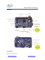
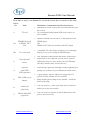
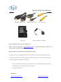
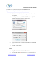
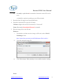
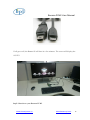
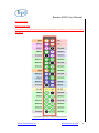
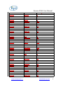
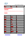
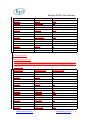
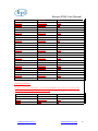
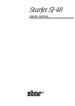
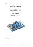
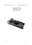
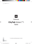
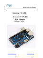
Banana PI M2 User Manual SinoVoip CO.,LTD Banana PI BPI-M2 User Manual <Version: V2.0 > www.sinovoip.com.cn www.banana-pi.com 1 Banana PI M2 User Manual Banana PI BPI-M2 is the open source hardware platform,Banana PI BPI-M2 is an quad core version of Banana Pi ,Banana PI BPI-M2 is the quad core more better than the Banana Pi BPI-M1,it support WIFI on board. Banana Pi BPI-M2 series run Android,Debian linux,Ubuntu linux, Raspberry Pi image and others image. Banana PI PBI-M2 hardware: 1Ghz ARM7 quad-core processor, 1GB DDR3 SDRAM, Banana PI BPI-M2with Gigabit ethernet port, It can run with Android 4.4 smoothly. The size of Banana PI BPI-M2 same as banana pi M1, it can easily run with the game it support 1080P high definition video output, the GPIO compatible with Raspberry Pi B+ and can run the ROM Image Note: Banana Pi BPI-M2 not support sata port, so you need use USB for hardisk www.sinovoip.com.cn www.banana-pi.com 2 Banana PI M2 User Manual Hardware Specification of Banana pi BPI-M2 Soc A31S ARM Cortex-A7 CPU A31S ARM Cortex-A7 quad-core,256 KB L1 cache 1 MB L2 cache GPU PowerVR SGX544MP2 · Comply with OpenGL ES 2.0, OpenCL 1.x, DX 9_3 SDRAM 1GB DDR3 (shared with GPU) Power 5V @ 2A via DC power and/or MicroUSB (OTG) Features Low-level perpherials 40 Pins Header,28×GPIO, some of which can be used for specific functions including UART, I2C, SPI, PWM, I2S, LRADC, ADC, LINE-IN. On board Network 10/100/1000Mbps ethernet (Realtek RTL8211E/D) Wifi Module WiFi 802.11 b/g/n (AP 6181 module on board) Bluetooth Optional On board Storage MicroSD (TF) card,Not SATA support Display Supports multi-channel HD display: HDMI 1.4 (Type A - full) LVDS/RGB/CPU display interface (DSI) for raw LCD panels 11 HDMI resolutions from 640×480 to 1920×1080 plus various PAL and NTSC standards Video HD H.264 2160p video decoding Mutil-format FHD video decoding, including Mpeg1/2, Mpeg4, H.263, H.264, etc H.264 high profile 1080p@30fps or 720p@60fps encoding Audio outputs HDMI,analog audio (via 3.5 mm TRRS jack shared with composite video out),I2S audio (also potentially for audio input) Camera Parallel 8-bit camera interface Audio input On board micphone USB 4 USB 2.0 host, 1 USB 2.0 OTG Buttons Reset button Power button&U-boot button Leds Power status Led and RJ45 Led Other IR reciever Interface definition Sizes 92 mm × 60mm Weight 45g www.sinovoip.com.cn www.banana-pi.com 3 Banana PI M2 User Manual Interface: Use method Step 1: Get what you need www.sinovoip.com.cn www.banana-pi.com 4 Banana PI M2 User Manual First time to enjoy your Banana Pi, you need at least the accessories in the table below. No. Item Minimum recommended specification & notes Minimum size 4Gb; class 4 (the class indicates how fast the card is). 1 TF card We recommend using branded SD cards as they are more reliable. 2a 2b HDMI to HDMI lead (for HD TVs and monitors with HDMI input). OR HDMI to DVI lead (for monitors with DVI input). A standard AV video lead to connect to your analogue display if you are not using the HDMI output. Any standard USB keyboard and mouse should work. Keyboards or mice that take a lot of power from the USB ports, however, may need a powered USB hub. This may include some wireless devices. HDMI(Full sized) to HDMI / DVI lead AV video lead 3 Keyboard and mouse 4 Ethernet cable/USB WiFi(Optional) 5 Micro USB power adapter 6 Audio lead (Optional) 7 Mobile Hard disk (Optional) www.sinovoip.com.cn Networking is optional, although it makes updating and getting new software for your Banana Pi much easier. A good quality, micro USB power supply that can provide at least 700mA at 5Vis essential. Many mobile phone chargers are suitable—check the label on the plug. You can choose a 3.5mm jack audio led to connect to audio port to get stereo audio. You can choose to connect a mobile hard disk to usb port to store more files. www.banana-pi.com 5 Banana PI M2 User Manual HDMI to HDMI lead HDMI to DVI lead SD card AV video lead Micro USB power adapter Step 2: Download the relevant Image file: Please visit our webmaster: www.bananapi.com image can be download form this web. to download image, banana pi all Step3: Prepare your SD card for the Banana Pi M2 In order to enjoy your Banana Pi M2, you will need to install an Operating System (OS) onto an SD card. Instructions below will teach you how to write an OS image to your SD card under Windows and Linux. 1. Insert your SD card into your computer. The size of SD should be larger than the OS image size, generally 4GB or greater. 2. Format the SD card. Windows: www.sinovoip.com.cn www.banana-pi.com 6 Banana PI M2 User Manual Download the a SD card format tool such as SD Formatter from https://www.sdcard.org/downloads/formatter_4/eula_windows/ i. Unzip the download file and run the setup.exe to install the tool on your machine. ii. In the "Options" menu, set "FORMAT TYPE" option to QUICK, "FORMAT SIZE ADJUSTMENT" option to "ON". iii. Check that the SD card you inserted matches the one selected by the Tool. iv. Click the “Format” button. Linux: v. vi. Run fdisk –l command to check the SD card node. Run sudo fdisk /dev/sdx command to delete all partition of SD card. www.sinovoip.com.cn www.banana-pi.com 7 Banana PI M2 User Manual vii. Run mkfs –t vfat /dev/sdx command to format the entire SD card as FAT. (x should be replaced according to your SD card node) 3. Download the OS image from Download district. 4. Unzip the download file to get the OS image. Windows: Right click on the file and choose “Extract all”. Linux: Run unzip [downloaded filename] command. 5. Write the image file to the SD card. Windows: i. Download a tool that can wirte image to SD card, such as Win32 Diskimager from: http://sourceforge.net/projects/win32diskimager/files/Archive/ ii. Open the unzipped image file. iii. Click Write button. Wait patiently to successfully complete writing. Linux: www.sinovoip.com.cn www.banana-pi.com 8 Banana PI M2 User Manual iv. Run fdisk –l command to check the SD card node. v. Run dd if=[imagename] of=/dev/sdx command to write image file to SD card. Wait patiently to successfully complete writing. Step4: Set up your Banana Pi M2 According to the set up diagram below, you can easily set up your Banana Pi. 1. Insert the written-image SD card that to the SD card spot on the left side edge of the underside of the board. 2. On the bottom "edge" in the middle of the board is the HDMI Type A (Full sized) port. Just connect any HDMI cable from the board to your TV or HDMI Monitor. If you don't have an TV/Monitor with a HDMI or DVI-D port you can use the yellow AV jack located in the middle of the "top" edge and the 3.5 mm stereo headphone jack to the right of it. 3. Plug a USB keyboard and mouse into the USB slots located on the right edge. 4. Just under the USB ports on the right edge is the ethernet connector for anyone who wants to plug the Banana Pi into a wired network. 5. Finally, at the very left of the bottom edge is the micro-usb power connector. Plug in a regulated power supply that is rated at 5V ±5% and at least 700mA (or 0.7A). Any number bigger than 700 mA (like 1000mA) will also work. Avoid using the smaller chargers used for small GSM phones, as these are often unregulated, even if they claim "5V 1A", they may do "5V" and may do "1A", but not at the same time! The mini-USB (on the left) is the wrong one. It’s thicker and looks like a trapezoid with its sides pinched in. The micro-USB (on the right) is the correct one. It is thinner and also looks like a trapezoid except it’s sides are rounded outward. www.sinovoip.com.cn www.banana-pi.com 9 Banana PI M2 User Manual If all goes well, the Banana Pi will boot in a few minutes. The screen will display the OS GUI. Step5: Shut down your Banana Pi M2 www.sinovoip.com.cn www.banana-pi.com 10 Banana PI M2 User Manual You can use the GUI to shut down the Banana Pi safely. Also you can run the command in the terminal: sudo halt or sudo shutdown –h. This will shut down the PI safely, (just use the power key to turn off might damage the SD-cards file system). After that you can press the power key for 5 seconds to turn it off. If all is well ,so you can use banana pi M2 now. www.sinovoip.com.cn www.banana-pi.com 11 Banana PI M2 User Manual GPIO specification Banana Pi 40-pin GPIO Banana Pi has a 40-pin GPIO header that matches that of the Model B+ Raspberry Pi. Following is the Banana Pi GPIO Pinout: www.sinovoip.com.cn www.banana-pi.com 12 Banana PI M2 User Manual GPIO Pin Name Default Function CN7-P01 CN7-P02 CN7-P03 CN7-P04 CN7-P05 CN7-P06 CN7-P07 CN7-P08 CN7-P09 CN7-P10 CN7-P11 CN7-P12 CN7-P13 CN7-P14 CN7-P15 CN7-P16 CN7-P17 CN7-P18 CN7-P19 CN7-P20 CN7-P21 CN7-P22 CN7-P23 CN7-P24 CN7-P25 CN7-P26 CN7-P27 CN7-P28 CN7-P29 CN7-P30 CN7-P31 CN7-P32 CN7-P33 CN7-P34 CN7-P35 CN7-P36 CN7-P37 CN7-P38 VCC-3V3 VCC-DC TWI2-SDA VCC-DC TWI2-SCK GND PWM1-P UART5_TX GND UART5_RX UART2_RX PWM1-N UART2_TX GND UART2_CTS PWM2-P VCC-3V3 PWM2-N SPI1_MOSI GND SPI1_MISO UART2_RTS SPI1_CLK SPI1_CS0 GND SPI1_CS1 TWI3-SDA TWI3-SCK I2S-MCLK GND I2S-BCLK I2S-DI I2S-LRCK GND I2S-DO0 UART5_RTS I2S-DO1 UART5_CTS www.sinovoip.com.cn Function2:GPIO PH19 PH18 PH9 PE4 PE5 PG7 PH10 PG6 PG9 PH11 PH12 PG15 PG16 PG8 PG14 PG13 PG12 PB6 PB5 PB0 PB1 PB7 PB2 PB3 PE6 PB4 PE7 www.banana-pi.com 13 Banana PI M2 User Manual CN7-P39 CN7-P40 GND 1WIRE PM2 CSI Camera Connector specification: CSI Camera Connector The CSI Camera Connector is a 40-pin FPC connector which can connect external camera module with proper signal pin mappings. The pin definitions of the CSI interface are shown as below. This is marked on the Banana Pi board as “CN6″. CSI Pin Name Default Function CN6-P01 CN6-P02 CN6-P03 CN6-P04 CN6-P05 CN6-P06 CN6-P07 CN6-P08 CN6-P09 CN6-P10 CN6-P11 CN6-P12 CN6-P13 CN6-P14 CN6-P15 CN6-P16 CN6-P17 CN6-P18 CN6-P19 CN6-P20 CN6-P21 CN6-P22 CN6-P23 CN6-P24 CN6-P25 LINEINL LINEINR VCC-CSI AVDD-CSI GND VDD-CSI MIC2P VCC-CSI MIC2N AFVCC-CSI GND CSI-IO0 LRADC0 TWI0-SDA MIC-MBIAS TWI0-SCK CSI-D4 CSI0-STBY-EN CSI-D5 CSI-PCLK CSI-D6 CSI0-PWR-EN CSI-D7 CSI-MCLK CSI-D8 www.sinovoip.com.cn Function2:GPIO PM0 PH15 PH14 PE8 PH27 PE9 PE0 PE10 PG18 PE11 PE1 PE12 www.banana-pi.com 14 Banana PI M2 User Manual CN6-P26 CN6-P27 CN6-P28 CN6-P29 CN6-P30 CN6-P31 CN6-P32 CN6-P33 CN6-P34 CN6-P35 CN6-P36 CN6-P37 CN6-P38 CN6-P39 CN6-P40 CSI0-RESET# CSI-D9 CSI-VSYNC CSI-D10 CSI-HSYNC CSI-D11 CSI1-STBY-EN AP-RESET# CSI1-RESET# CSI-IO1 HPR HPL IPSOUT GND IPSOUT PH26 PE13 PE3 PE14 PE2 PE15 PH25 PH24 PM1 LVDS specification LVDS (LCD display interface) The LVDS Connector is a 40-pin FPC connector which can connect external LCD panel (LVDS) and touch screen (I2C) module as well. The pin definitions of this connector are shown as below. This is marked on the Banana Pi board as “CN9″. DSI Pin Name Default Function CN9-P01 CN9-P02 CN9-P03 CN9-P04 CN9-P05 CN9-P06 CN9-P07 CN9-P08 CN9-P09 CN9-P10 CN9-P11 CN9-P12 CN9-P13 CN9-P14 CN9-P15 CN9-P16 IPSOUT TWI1-SDA IPSOUT TWI1-SCK GND TP-INT LCD-PWR-EN TP-RST LCD0-D00 LCD0-PWM LCD0-D01 LCD0-BL-EN LCD0-D02 LCD0-DE LCD0-D03 LCD0-VSYNC www.sinovoip.com.cn Function2:GPIO PH15 PH16 PG0 PG4 PG1 PD0 PH13 PD1 PG3 PD2 PD25 PD3 PD27 www.banana-pi.com 15 Banana PI M2 User Manual CN9-P17 CN9-P18 CN9-P19 CN9-P20 CN9-P21 CN9-P22 CN9-P23 CN9-P24 CN9-P25 CN9-P26 CN9-P27 CN9-P28 CN9-P29 CN9-P30 CN9-P31 CN9-P32 CN9-P33 CN9-P34 CN9-P35 CN9-P36 CN9-P37 CN9-P38 CN9-P39 CN9-P40 LCD0-D04 LCD0-HSYNC LCD0-D05 LCD0-CS LCD0-D06 LCD0-CLK LCD0-D07 GND LCD0-D08 LCD0-D23 LCD0-D09 LCD0-D22 LCD0-D10 LCD0-D21 LCD0-D11 LCD0-D20 LCD0-D12 LCD0-D19 LCD0-D13 LCD0-D18 LCD0-D14 LCD0-D17 LCD0-D15 LCD0-D16 PD4 PD26 PD5 PG2 PD6 PD24 PD7 PD8 PD23 PD9 PD22 PD10 PD21 PD11 PD20 PD12 PD19 PD13 PD18 PD14 PD17 PD15 PD16 UART specification: The header CON4 is the UART interface. For developers of Banana Pi, this is an easy way to get the UART console output to check the system status and log message. CN8 Pin Name Default Function GPIO CN8 P03 UART0-TXD PH20 CN8 P02 UART0-RXD PH21 CN8 P01 GND www.sinovoip.com.cn www.banana-pi.com 16