1
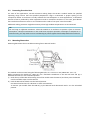
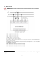
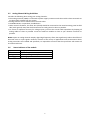
VIBRATION MONITOR CX-RLY MaintTech Norrkoping Airport Sweden Email: [email protected] Website: www.mainttech.se 1 CX-RLY-C MODULE Version 1 1 Important User Information Solid-state equipment has operational characteristics differing from those of electromechanical equipment. Safety Guidelines for the Application, Installation, and Maintenance of Solid State Controls describes some important differences between solid-state equipment and hard-wired electromechanical devices. Because of this difference, and because of the wide variety of uses for solid-state equipment, all persons responsible for applying this equipment must satisfy themselves that each intended application of this equipment is acceptable. Throughout this manual, when necessary, we use notes to make you aware of safety considerations. ATTENTION: Identifies information about practices or circumstances that can lead to personal injury or death, property damage, or economic loss. Attentions help you identify a hazard, avoid a hazard, and recognize the consequence IMPORTANT Identifies information that is critical for a successful application and understanding of the product. The CX-RLY-C module is built using a Micro810™ 12 Point Programmable Controller. A more detailed description of how to install and use the Micro810 programmable controller may be found on the following link: http://ab.rockwellautomation.com/Programmable-Controllers/Micro810 2 Overview The CX-RLY-C Modules are smart relays with high current relay output models and can be configured through the embedded LCD display without any programming software. 2.1 Installation Considerations Locate your modules as far as possible from power lines, load lines, and other sources of electrical noise such as hard-contact switches, relays, and AC motor drives. WARNING: Exposure to some chemicals may degrade the sealing properties of the materials used in the Relays. It is recommended to the User to inspect these devices periodically to observe any degradation of properties and to replace the module if degradation is found. WARNING: To comply with the CE Low Voltage Directive (LVD), this equipment must be powered from a source compliant with the following: Safety Extra Low Voltage (SELV) or Protected Extra Low Voltage (PELV). WARNING: Do not wire more than two conductors on any single terminal. WARNING: Be careful when stripping wires. Wire fragments that fall into the module could cause damage. Once wiring is complete, make sure the controller is free of all metal fragments. ATTENTION: This product is intended to be mounted to a well-grounded mounting surface such as a metal panel. Additional grounding connections from the power supply mounting tabs or DIN rail (if used) are not required unless the mounting surface cannot be grounded. ATTENTION: Circuits installed on the machine for safety reasons and interlocks, should always be hard-wired directly to the master control relay. These devices must be wired in series so that when any one device opens, the master control relay is de-energized, thereby removing power to the machine. Never alter these circuits to defeat their function. Serious injury or machine damage could result. 2 2.2 Preventing Excessive Heat For most of the applications, normal convective cooling keeps the CX-RLY-C module within the specified operating range. Ensure that the specified temperature range is maintained. A proper spacing of the components within an enclosure is usually sufficient for heat dissipation. In some applications, a substantial amount of heat is produced by other equipments inside or outside the enclosure. In this case, place blower fans inside the enclosure to assist in air circulation and to reduce “hot spots” near the module. Additional cooling provisions might be necessary when high ambient temperatures are encountered. TIP Do not bring in unfiltered outside air. Place the module in an enclosure to protect it from a corrosive atmosphere. Harmful contaminants or dirt could cause improper operation or damage to components. In extreme cases, you may need to use air conditioning to protect against heat buildup within the enclosure. 2.3 Mounting Dimensions Mounting dimensions do not include mounting feet or DIN rail latches. The module can be mounted using the following DIN rails: 35 x 7.5 mm x 1 mm (EN 50 022 - 35 x 7.5). Before mounting the module on a DIN rail, use a flat-blade screwdriver in the DIN rail latch and pry it downwards until it is in the unlatched position. a) Hook the top of the DIN rail mounting area of the module onto the DIN rail, and then press the bottom until the module snaps onto the DIN rail. b) Push the DIN rail latch back into the latched position. Use DIN rail end anchors for vibration or shock environments. To remove your module from the DIN rail, pry the DIN rail latch downwards until it is in the unlatched position. 3 2.4 Wiring Diagram WARNING: Before installing and wiring any device, just disconnect power supply of the module. The following picture shows the wiring diagram of the module: AI11 – Analogical Input 1 (0..6 V dc) AI21 – Analogical Input 2 (0..6 V dc) AI31 – Analogical Input 2 (0..6 V dc) AI41 – Analogical Input 2 (0..6 V dc) ACOM – Common for Analogical Input B1 – LOCK. When closes, locks the keypad. B2 – STARTUP. When a transition from “0” to “1” occurs, the alarm limits will be multiplied with a factor of 2, for 10 seconds. B3 – INHIBIT – When closes, inhibits the relays action. Relays will be placed in no-alarm status (NC or NO, depending on B4 input). RLY1 – RELAY 1 free contact (can be set to NC or to NO). RLY2 – RELAY 2 free contact (can be set to NC or to NO). RLY3 – RELAY 3 free contact (can be set to NC or to NO). RLY4 – RELAY 4 free contact (can be set to NC or to NO). 1 AI2, AI3 and AI4 analogical inputs can be used to disable Channel 4, 3 and 2. See "4.1. Channel configuration" paragraph. 4 2.5 Analog Channel Wiring Guidelines Consider the following when wiring your analog channels: • The analog common (COM) is connected to power supply common inside the module. These terminals are not electrically isolated from the system. • Analog channels are not isolated one from each other. • Use Belden 8761, or equivalent, shielded wire. • Under normal conditions, the drain wire (shield) should be connected to the metal mounting panel at field side (earth ground). Keep the shield connection to earth ground as short as possible. • To ensure an optimum accuracy for voltage inputs, just limit the overall cable impedance by keeping all analog cables as short as possible. Locate the CX-RLY-C module as close to your vibration converter as possible. NOTE: Inputs on analog channels employ digital high-frequency filters that significantly reduce the effects of electrical noise on input signals. However, because of the variety of applications and environments where analog controllers are installed and operated, it is impossible to ensure that the input filters will remove all environmental noise. 2.6 State Status Indicator of the module During Operation Off No power applied to device, or in Fault mode Solid green Device operating normally Flashing green Operating System error 5 3 CX-RLY-C SPECIFICATION Parameter Number of I/O Dimensions HxWxD Supply voltage range Power consumption I/O rating Shipping weight, approx. Wire size Enclosure type rating DC Inputs On-state voltage, nom On-state voltage, min On-state voltage, max Off-state current, max On-state current, min On-state current, nom On-state current, max Nominal impedance Analog Inputs Input type Input voltage range Input voltage, max Value of LSB Overall accuracy CX-RLY-C 8 Input (4 digital, 4 analog/digital) 4 Output 91 x 75 x 59 mm 20.4…26.4V DC 3W Input: 24V DC, 8 mA Relay : 4 A @ 240V AC 0.203 kg 0.32... 2.1 mm² (22...14 AWG) solid copper wire or 0.32... 1.3 mm² (22...16 AWG) stranded copper wire rated @ 90 °C insulation max. Meets IP20 12/24V DC 9.8V DC 28.8V DC 0.5 mA 0.75 mA @ 10.8V DC 1.0 mA @ 15V DC 2.1 mA @ 24V DC 2.7 mA @ 28.8V DC 14.1 KOhm DC voltage 0…6V DC accepted 26.4V DC 10 mV 2% of full-scale (with calibration) (25…55 °C) Noise rejection 50/60 Hz Common mode rejection 40 dB, DC to 60 Hz with smoothing filter Nominal impedance 14.1 kΩ (non-isolated) Relay Outputs Output rating 4 A @ 240V AC, 2 A @ 24V DC, Voltage, min 5V AC/DC Voltage, max 250V AC, 30V DC @ rated current. Mechanical 10,000,000 cycles Electrical with rated load 50,000 cycles Environmental Temperature, operating IEC 60068-2-1 (Test Ad, Operating Cold), IEC 60068-2-2 (Test Bd, Operating Dry Heat), IEC 60068-2-14 (Test Nb, Operating Thermal Shock): 0…55 °C Surrounding air 55 °C temperature, max. Temperature, storage -40…85 °C 6 Relative humidity Vibration Shock, operating Shock, non-operating ESD immunity Certifications CE IEC 60068-2-30 (Test Db, Unpackaged Damp Heat): 5...95% non-condensing IEC 60068-2-6 (Test Fc, Operating): 2 g @ 10…500 Hz IEC 60068-2-27 (Test Ea, Unpackaged Shock): 30 g IEC 60068-2-27 (Test Ea, Unpackaged Shock): 30 g (DIN Rail Mounted) IEC 61000-4-2: 4 kV contact discharges 8 kV air discharges European Union 2004/108/EC EMC Directive, compliant with: EN 61000-6-2; Industrial Immunity EN 61000-6-4; Industrial Emissions Access the module Configuration Menu Press ESC and OK at the same time, to access the Main Menu screen. Accessing this menu when the machine is running can lead to personal injury or death, property damage, or economic loss. Before accessing this menu, be sure that the machine is not running. For safety reasons, the Configuration menu is password protected. 7 4 Functional description 4.1 Channel configuration WARNING: Before you configure and wire any device, disconnect power to the module. The CX-RLY-C module can be configured to accept 1, 2, 3 or 4 analogical inputs. Inputs 2, 3 and 4 can be disabled. In the channel configuration, there are a few restrictions: - Channel 2 can be disabled only if channels 3 and 4 are also disabled. - Channel 3 can be disabled only if channel 4 is also disabled. - Channel 4 can be disabled without any restriction. To disable a channel, just connect the selected input to +24 V. In the following tables are presented the options: Table 1 - Channel 4 disabled Input AI1 AI2 AI3 AI4 Connection To analogical source (0..5V dc or 1..5V) To analogical source (0..5V dc or 1..5V) To analogical source (0..5V dc or 1..5V) Connect to +24V Table 2 - Channel 3 and 4 disabled Input AI1 AI2 AI3 AI4 Connection To analogical source (0..5V dc or 1..5V) To analogical source (0..5V dc or 1..5V) Connect to +24V Connect to +24V Table 3 - Channel 2, 3 and 4 disabled Input AI1 AI2 AI3 AI4 Connection To analogical source (0..5V dc or 1..5V) Connect to +24V Connect to +24V Connect to +24V Table 4 - All channels enabled Input AI1 AI2 AI3 AI4 Connection To analogical source (0..5V dc or 1..5V) To analogical source (0..5V dc or 1..5V) To analogical source (0..5V dc or 1..5V) To analogical source (0..5V dc or 1..5V) 8 4.2 KEYPAD The module keypad has 6 keys. UP/DOWN arrow keys In the Main Screen: these keys select an analogical channel. In the Setting screens: with these keys the set value can be changed. OK Key In the Main Screen: when pressing this key, the software will move to the first Setting screen (for the selected channel). In the Setting screens: Save the setting after it was changed. LEFT/RIGHT arrow keys In the Main Screen, these keys are not used. In the Setting screens, these keys browse between the Setting screens (for the selected channel). ESC key In the Main screen: By pressing this key, the software will access the GENERAL Setting screen. In the Setting screens, the key may be used to return directly to the Main Screen. 4.3 Main Screen Main screen is always the first one that appears. The vibration values coming from the analogical inputs are shown in four lines. CH1 CH2 CH3 CH4 7.8 mm/s mm/s 3.2 mm/s 4.1 mm/s mm/s 1.3 mm/s mm/s Press to select a channel. This action is required, if you need to change the channel setting. After selection, just press access the Setting menu. Press (3 seconds) setting screen. to to access the GENERAL Depending on the general hardware settings and depending on the alarm condition, the Main screen can look like below (Refer to paragraph 2.4 "Wiring Diagram"). 4.3.1 The keypad is locked CH1 CH2 CH3 CH4 7.8 3.2 4.1 1.3 mm/s mm/s mm/s mm/s I-00 Digital input is connected to +24 V (LOCK=True) Selection arrow sign is not visible. This hardware setting disables the access to the Setting screens. 9 4.3.2 The relay is inhibited I-02 Digital input is connected to +24 V (INHIBIT =True) CH1 CH2 CH3 CH4 4.3.3 INH INH INH INH When the relay is inhibited, the alarm condition is not evaluated and the relays will be placed in non-alarm condition (NC or NO, depending on I-03 hardware status). Normally, it is necessary to place the CX-RLY-C module in this status, only for troubleshooting. A channel is in alarm condition CH1 CH2 CH3 CH4 4.4 7.8 3.2 4.1 1.3 7.8 3.2 WAR 4.1 DNG 1.3 In the picture, CH2 is in alarm status (the measured value is above the set Warning). CH3 is also in Danger status. The correspondent relay will act only when the delay time will expire. GENERAL setting screens Accessing this menu when the machine is running can lead to personal injury or death, property damage, or economic loss. Before accessing this menu, be sure that the machine is not running. CX-RLY-C accepts two voltage ranges: 0-5 V dc or 1-5 V d.c. To access this screen, from the Main screen just press ESC for 3 seconds. 4.4.1 INPUT CONFIG SCREEN INPUT CONFIG 0 – 5 V Save? OK Main Next Use / arrows to change the voltage input range. Press OK to save the settings. Press ESC to exit to the Main screen. NOTE: 1 - 5 V setting is suitable for Loop Vibration Sensor having a 4...20 mA output. Press to return to the Main screen. Press to go to the RLY #1 NORMAL position screen. 4.4.2 RELAY NORMAL POSITION RLY1 NORMAL CLOSE Save? OK Prev Next Use / arrows to change the Relay #1 normal position (CLOSE or OPEN). Press OK to save the settings. Press ESC to exit to the Main screen. Press to return to the INPUT CONFIG screen. Press to go to the RLY #2 NORMAL position screen. The next three screens are similar, for setting RLY #2, RLY #3 and RLY #4. 10 NOTE: Relay normal position defines the contact status in NORMAL operation (NO alarm), as follows: - CLOSE - In NO alarm condition the relay coil is energized and the relay contact is closed. - OPEN - In NO alarm condition the relay coil is de-energized and the relay contact is opened. 4.5 SETTING Screens For each channel, there are 6 Settings screens: - RANGE screen - WARNING screen - DANGER screen - DELAY screen - WARNING RLY mapping - DANGER RLY mapping To entry in the SETTING screens, from the Main screen, first select the channel and then press OK. The settings for CH1 are shown below. For the other channels, the settings will be done in a similar manner. 4.5.1 RANGE SETTING SCREEN CH1 - Range 10.0 Save? OK Main Next Use / arrows to change the range value, in a step of 10. The selection can be done for ranges between 10 and 100. Press OK to save the new settings. The third line is visible only when the new value is not the same with the previous saved value. Press to return to the Main screen. Press to go to the Warning screen. Press ESC to return to the Main screen directly. WARNING: The range must be set according with the range of the the vibration converter. A wrong setting can let the machine without protection. 4.5.2 WARNING SETTING SCREEN CH1 - Warning 12.3 Save? OK Prev Next Use the / arrows to change the Warning value, in a step of 0.1. The selection can be done for the alarm between 0.1 and the Range value, already set in the screen above. To accelerate the modifying procedure, just press the / arrows for a couple of seconds. Press OK to save the new setting. The third line is visible only when the new value is not the same with the previous saved value. Press to return to the Range screen. Press to go to the Danger screen. Press ESC to return directly to the Main screen. 11 4.5.3 DANGER SETTING SCREEN CH1 - Danger 12.3 Save? OK Prev Next Use / arrows to change the Danger value, in a step of 1. The selection can be done for ranges between 0 and 10. Press OK to save the new setting. The third line is visible only when the new value is different from the previous saved value. Press to return to Warning screen. Press to go to the Danger screen. Press ESC to return directly to the Main screen. 4.5.4 DELAY SETTING SCREEN CH1 - Delay 3.0 sec Save? OK Prev Next Use / arrows to change the Delay value, in a step of 0.1 seconds. Press OK to save the new settings. The third line is visible only when the new value is not the same with the previous saved value. Press to return to Danger screen. Press to go to the next screen. Press ESC to return to the MAIN screen directly. The Delay setting is used to add a delay time for relay action. If an alarm condition occurs and a Delay time is set (non-zero value), the relay will act only if the alarm condition persists more than the set delay time. Otherwise, the relay will not act. With another words, if the alarm condition persists less than Delay setting, the relay will remain in nonalarm condition (NO or NC). WARNING: A too long delay time is not recommended. To avoid early trip during machine startup, just use instead the STARTUP digital input. (See paragraph 4.4) WARNING: During the setting procedure, the software doesn’t evaluate the alarm condition and the relay won’t be activated. The machine remains without protection! For safety reasons, the parameter settings must be done when the machine is stopped. 4.5.5 WARNING RLY MAPPING SCREEN CH1 - Map Warn None Save? OK Prev Next Use / arrows to change the mapping: Selection: None, RLY1, RLY2, RLY3, RLY4. Press OK to save the new settings. The third line is visible only when the new value is not the same with the previous saved value. Press to return to previous screen. Press to go to the next screen. Press ESC to return to the Main screen directly. 12 4.5.6 DANGER RLY MAPPING SCREEN Use / arrows to change the mapping: Selection: None, RLY1, RLY2, RLY3, RLY4. Press OK to save the new settings. The third line is visible only when the new value is not the same with the previous saved value. Press to return to previous screen. Press to go to the next screen. Press ESC to return to the Main screen directly. These settings must be logically done, otherwise unexpected relay actions may occur. CH1 - Map Dang RLY2 Save? OK Prev Main Example 1 - Wrong relay mapping Assuming that the RLY1 mapping was done as follows: - CH1 Map Warn -> RLY1 - CH1 Map Dang -> RLY1 In this case, when a Warning alarm condition is met, the RLY1 will act, but nothing happens when a Danger alarm of CH1 occurs (RLY1 is already activated). Example 2 - Wrong relay mapping - CH1 MAP WARN -> RLY1 - CH2 MAP DANG -> RLY1 Above setting not have any sense. RLY1 is acting for two independent events, having nothing in common. Example 3 - Correct relay mapping Consider a CX-RLY-C used for a single machine, having four transducers. A possible relay mapping is: - RLY1 - Warning alarm (for all four channels: CH1, CH2, CH3 and CH4) - RLY2 - Danger alarm (for all four channels: CH1, CH2, CH3 and CH4) - RLY 3 - Set to NONE (unused) - RLY 4 - Set to NONE (unused). Example 4 - Correct relay mapping Considering a CX-RLY-C used for two machines: - Machine #1 - CH1 and CH2 - Machine #2 - CH3 and CH4 A suitable relay mapping may be this: - RLY1 - Warning alarm for Machine#1 (CH1 Map Warn -> RLY1 and CH2 Map Warn-> RLY1) - RLY2 - Danger alarm for Machine#1 (CH1 Map Dang-> RLY2 and CH2 Map Dang -> RLY2) - RLY3 - Warning alarm for Machine#2 (CH3 Map Warn -> RLY3 and CH4 Map Warn-> RLY3) - RLY4 - Danger alarm for Machine#2 (CH4 Map Dang-> RLY3 and CH4 Map Dang -> RLY3) Example 5. Correct relay mapping Map the relay as follows: - RLY1 - Danger alarm for CH1 (CH1 Map Dang -> RLY1) - RLY2 - Danger alarm for CH2 (CH2 Map Dang -> RLY2) - RLY3 - Danger alarm for CH3 (CH3 Map Dang -> RLY3) - RLY4 - Danger alarm for CH4 (CH4 Map Dang -> RLY4) 13 4.6 STARTUP hardware switch During start-up, a higher vibration value is expected. To inhibit the alarm is not a suitable action, because the machine will remain for a while without protection for over-vibration. That’s why, in CX-RLY-C software was implemented a function which can, by demand, to double the set alarm limits. This function must be used in conjunction with the digital input I-01 (STARTUP). When a transition from “0” to “1” occurs, the alarm limits will always be multiplied by a factor of 2, for 10 seconds only. This time allows the machine to stabilize when starts. If still exaggerate vibration values are measured, the machine will be stopped. After 10 seconds, the I-01 (STARTUP) input is ignored, until the next low-to-high transition. This input must be always activated by an external relay, when the machine starts. Trough the external relay contact, feed to the I-02 digital input a +24 V voltage. 4.7 Alarm hysteresis To avoid repeatedly switching of the relay contact, a hysteresis gap has been implemented. The hysteresis value is 3% of the set RANGE. See below the relay switching diagram: The hysteresis value is fixed and cannot be adjusted in this software release. 14