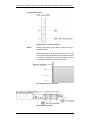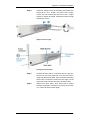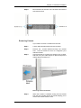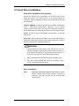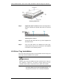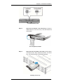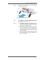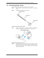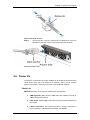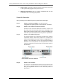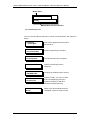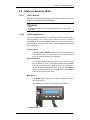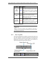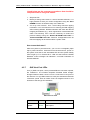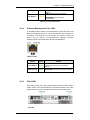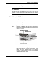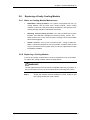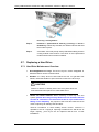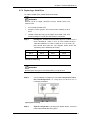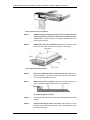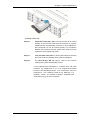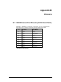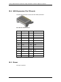
1
Galaxy® HDX4 ISO 9001:2008 ISO 13485:2003 Certified MODELS: »G X4L_2120S4_12I1 12 BAY iSCSI Quad 1Gb to SAS/SATA II RAID Subsystem Single Controller Installation and Hardware Reference Manual Galaxy HDX4 12 Bay RAID iSCSI Host SAS / SATA Drives 7th Generation Fibre Channel RAID With over 10,000 Galaxy units in the field, Rorke Data’s award winning RAID products provide the performance, protection, and expansion capabilities for diverse customer environments. PLEASE READ BEFORE INSTALLATION www.rorke.com GX4L_2120S4_12I10411_HMN Rorke Data, An Avnet Company 7626 Golden Triangle Drive, Eden Prairie, MN 55344, USA » Toll Free 1.800.328.8147 » Phone 1.952.829.0300 » Fax 1.952.829.0988 Contact Information Americas Rorke Data Inc 7626 Golden Triangle Drive Eden Prairie, MN 55344 USA Tel: +1-800 328 8147 Fax: +1-952 829 0988 1 [email protected] http://www.rorke.com Galaxy GHDX4 iSCSI<>-SAS / SATA 12Bay Installation / Hardware Reference Manual Copyright 2010 This Edition First Published 2010 All r ights r eserved. T his publ ication m ay no t be r eproduced, t ransmitted, transcribed, stored in a retrieval system, or translated into any language or computer language, in any form or by any means, electronic, mechanical, magnetic, optical, chemical, manual or otherwise, without the prior written consent of Rorke Data, Inc. Disclaimer Rorke Technology makes no representations or warranties with respect t o t he c ontents her eof and s pecifically d isclaims an y implied warranties of merchantability or f itness f or an y p articular pur pose. Furthermore, Rorke Data reserves the right to revise this publication and to make changes from time to time in the content hereof without obligation to notify any person of such revisions or changes. Product specifications are also subject to change without prior notice. Trademarks Galaxy and the Galaxy logo are registered trademarks of Rorke Data, Inc. Solaris and Java are trademarks of Sun Microsystems, Inc. All o ther names, br ands, products or s ervices ar e trademarks or registered trademarks of their respective owners. ii Galaxy Raid Installation and Hardware Reference Manual Warnings and Certifications RESTRICTED ACCESS LOCATION: This equi pment i s intended t o be i nstalled in a R ESTRICTED A CCESS LOCATION only. Access can only be gained by SERVICE PERSONS or by USERS who ha ve been i nstructed abou t t he r easons f or t he r estrictions applied t o t he l ocation and ab out any pr ecautions t hat s hall be taken; and Access is by an authorized person through the use of a TOOL or lock and key, or other means of security, and is controlled by the authority responsible for the location. ELECTRIC SHOCK WARNING! To Prevent Electric Shock: 1. Access t o t his equ ipment is gr anted only to t rained op erators an d service personnel who h ave been instructed of a nd f ully u nderstand the possible hazardous conditions and the consequences of accessing non-field-serviceable units, e.g., system backplane or power supplies. 2. Unplug the s ystem bef ore you m ove i t or damaged. when i t has bec ome RELIABLE EARTHING! Particular a ttention s hould be g iven to pr epare r eliable earthing with t he power supply connections other than direct connections to the branch circuit (e.g., us e of po wer strips). T he A C po wer c ords pr ovide t he m ain ear th connection. Check proper grounding before powering on the enclosure. OVERLOADING PROTECTION! 1. The enclosure should be installed according to specifications on a chassis l abel. P rovide a s uitable po wer s ource w ith electrical o verload protection. 2. Do not overload the AC supply branch circuit that provides power to the rack. T he t otal r ack l oad should n ot ex ceed 8 0 percent of t he br anch circuit rating. BATTERY USE WARNING! Risk of explosion if battery is replaced by an incorrect type. Dispose of used batteries according to local ordinance. iii Galaxy GHDX4 iSCSI<>-SAS / SATA 12Bay Installation / Hardware Reference Manual THERMAL PRECAUTIONS: 1. If installed in a closed or multi-unit rack assembly, the operating ambient temperature of the rack environment may be greater than room ambient. Appropriate m easures, s uch as increasing a irflow, s hould b e available to maintain the temperature below 35°C. 2. The openings on the enclosure are for air convection. DO NOT COVER THE OPENINGS. 3. To comply with safety, emission, and thermal requirements, all module bays should be populated with plug-in modules. The system should not be operated with the absence of any covers. HANDLING PRECAUTIONS: 1. The s ystem c an ei ther be i nstalled i nto a s tandard EIA-310 1 9” r ack cabinet or placed o n a desktop. Mec hanical loading of t he e nclosure should be carefully handled to avoid hazardous condition. A drop or fall could cause injury. 2. Lay this system on a r eliable surface with desktop installation. A drop or fall can cause injury. 3. Mounting this enclosure requires two people. 4. The enc losure c an weigh up t o 37Lbs ( 17kg) without di sk dr ives. With disk drives loaded, the enclosure can weigh up to 60lb (24kg). A reliable surface should be available to support this weight. 5. Disk drives should be installed after the enclosure is securely installed. iv Galaxy Raid Installation and Hardware Reference Manual FCC (applies in the U.S. and Canada) FCC Class A Radio Frequency Interference Statement This dev ice c omplies with P art 15 of t he F CC r ules. O peration i s subject to the following two conditions: (1) this device may not cause harmful interference, and (2) this device may accept any interference received, including interference that may cause undesired operation. NOTE: This equipment has been tested and found to comply with the limits for a C lass A di gital de vice, pur suant t o Part 15 of t he F CC R ules. These l imits ar e des igned t o pr ovide r easonable protection a gainst harmful interference when the equipment is operated in a commercial environment. This equipment generates, uses, and can radiate radio frequency energy and, i f n ot i nstalled an d us ed i n a ccordance with the instruction manual, may cause harmful interference to radio communications. Operation of this equipment in a residential area is likely t o c ause har mful i nterference i n which c ase t he us er will b e required to correct the interference at his own expense. Any c hanges or modifications not ex pressly a pproved by t he par ty responsible for compliance could void the user’s authority to operate the equipment. WARNING: A s hielded po wer c ord i s r equired i n order t o m eet F CC em ission limits and also to prevent interference to nearby radio and television reception. Use on ly s hielded c ables t o c onnect I /O devices t o t his e quipment. You ar e c autioned t hat changes or m odifications not expressly approved by t he par ty r esponsible f or c ompliance c ould v oid your authority to operate the equipment. This device is in conformity with the EMC. CB (Certified Worldwide) This dev ice m eets t he r equirements of t he C B s tandard f or electrical equipment with regard to establishing a satisfactory level of safety for per sons using the device and f or the area surrounding t he app aratus. T his s tandard c overs onl y s afety aspects of the above apparatus; it does not cover other matters, such as style or performance. v Galaxy GHDX4 iSCSI<>-SAS / SATA 12Bay Installation / Hardware Reference Manual CCC For P ower S upplies’ c ompatibility to China Compulsory Certification. China RoHS In Compliance with AeA China RoHS Regulations (SJ/T 11364-2006) ITE BSMI Class A, CNS 13438 (for Taiwan) This device is in conformity with UL standards for safety. Инструкция по безопасности Модель: FC to SAS/SATA 3U/16, 4U/24 Bay RAID Subsystem, Models, where “x” can be “0-9”, “A-Z“, blank, or dash “x” for marketing purpose and no impact safety related critical components and constructions. 1. 2. 3. 4. 5. 6. 7. 8. 9. vi Перед использованием оборудования внимательно прочтите инструкцию. Сохраняйте инструкцию для дальнейшего использования в работе. Не допускайте попадания влаги на изделие. Устанавливайте оборудование на устойчивую поверхность. Падение может нанести ущерб оборудованию. Соблюдайте климатические требования, использование оборудование при температуре окружающей среды выше 50°С, может привести к выходу оборудования из строя. Размещайте шнур питания в недоступном для пользователя месте. Запрещается ставить на шнур питания какие-либо предметы. При работе с оборудованием необходимо учитывать все предупреждения и замечания. Если оборудование не используется в течении длительного времени, отключите его от сети питания. Запрещается вскрывать оборудование. Оборудование может Galaxy Raid Installation and Hardware Reference Manual вскрываться только квалифицированным персоналом. 10. При возникновении одного из повреждений оборудования вызовите обслуживающий персонал: a. Повреждение шнура питания или вилки. b. Оборудование не работает или его работа не соответствует инструкции пользователя . e. Оборудование повреждено. f. Оборудование имеет очевидный признак поломки. 11. Источник питания должен быть установлен в соответствии с инструкцией. Ток нагрузки и выходная мощность не должны превышать указанных в спецификации. Rorke is committed to being properly prepared and taking all the necessary steps that will result in our compliance with the new European d irective, RoHS ( 2002/95/EC), on o r bef ore the specific dates set forth in those applicable laws and regulations. Rorke is ap plying its o wn i nternal ef forts and expertise and is working closely with customers and suppliers to achieve compliance while maintaining an uninterrupted supply of qual ity products. Rorke is c urrently i nvestigating, evaluating, a nd q ualifying our m aterials and c omponents t o ensure t hat pr oducts s old on or af ter 1 J uly 20 06, in s uch territory, are in compliance with the above regulations. Disposal of Old Electrical & Electronic Equipment (Applicable in t he E uropean U nion and ot her E uropean c ountries with separate collection systems) This symbol on the product or on its packaging indicates that this product shall not be treated as household waste. Instead it s hall be ha nded o ver t o t he a pplicable c ollection point f or the recycling of electrical and electronic equipment. By proper waste handling of this product you ensure that it has no negative c onsequences f or t he environment and hum an health, which c ould o therwise b e c aused i f t his pr oduct is thrown into t he gar bage bin. The r ecycling of m aterials will help to conserve natural resources. For m ore det ails ab out r ecycling of t his pr oduct, please contact your l ocal c ity of fice, your hous ehold w aste disposal service or the shop where you purchased the product. } vii Galaxy GHDX4 iSCSI<>-SAS / SATA 12Bay Installation / Hardware Reference Manual Table of Contents CONTACT INFORMATION ............................................................ ERROR! BOOKMARK NOT DEFINED. COPYRIGHT 2010 ..................................................................... ERROR! BOOKMARK NOT DEFINED. This Edition First Published 2010 ........................................ Error! Bookmark not defined. Disclaimer Error! Bookmark not defined. Trademarks ......................................................................... Error! Bookmark not defined. W ARNINGS AND CERTIFICATIONS ................................................ ERROR! BOOKMARK NOT DEFINED. TABLE OF CONTENTS ...............................................................................................................VIII SAFETY PRECAUTIONS .............................................................. ERROR! BOOKMARK NOT DEFINED. Precautions and Instructions ............................................... Error! Bookmark not defined. ESD Precautions ................................................................. Error! Bookmark not defined. ABOUT THIS MANUAL ................................................................ ERROR! BOOKMARK NOT DEFINED. REVISION HISTORY ................................................................... ERROR! BOOKMARK NOT DEFINED. WHO SHOULD READ THIS MANUAL? ............................................. ERROR! BOOKMARK NOT DEFINED. Related Documentation ....................................................... Error! Bookmark not defined. CONVENTIONS .......................................................................... ERROR! BOOKMARK NOT DEFINED. Naming Error! Bookmark not defined. Lists Error! Bookmark not defined. Important Information........................................................... Error! Bookmark not defined. SOFTWARE AND FIRMWARE UPDATES ......................................... ERROR! BOOKMARK NOT DEFINED. CHAPTER 1: INTRODUCTION 1.1 PRODUCT OVERVIEW ..................................................................................................... 1 1.1.1 Introduction........................................................................................................... 1 1.1.2 Enclosure Chassis................................................................................................ 2 1.2 SYSTEM COMPONENTS .................................................................................................. 5 1.2.1 Drive Trays ........................................................................................................... 5 1.2.2 The RAID Controller Module ................................................................................ 5 1.2.3 Controller Module Interfaces ................................................................................ 6 1.2.4 Cache Module ...................................................................................................... 7 1.2.5 CBM (Optional Feature) ....................................................................................... 7 1.2.6 Power Supply Units .............................................................................................. 9 1.2.7 Cooling Modules................................................................................................... 9 1.3 SYSTEM MONITORING .................................................................................................. 10 1.3.1 I2C bus ............................................................................................................... 10 1.3.2 LED Indicators .................................................................................................... 10 1.3.3 Audible Alarms ................................................................................................... 11 1.4 HOT-SWAPPABLE COMPONENTS.................................................................................... 11 1.4.1 Hot-swap Capabilities ......................................................................................... 11 1.4.2 Components ....................................................................................................... 12 1.4.3 Normalized Airflow ............................................................................................. 12 CHAPTER 2: HARDWARE INSTALLATION 2.1 INTRODUCTION .............................................................................................................. 1 2.2 INSTALLATION PREREQUISITES ........................................................................................ 1 2.3 SAFETY PRECAUTIONS ................................................................................................... 3 2.3.1 Precautions and Instructions ................................................................................ 3 2.3.2 Static-free Installation ........................................................................................... 6 2.4 GENERAL INSTALLATION PROCEDURE .............................................................................. 7 2.4.1 Installation Procedure Flowchart................................................................................. 7 2.5 UNPACKING THE SYSTEM ............................................................................................... 7 Preinstalled Components..................................................................................................... 9 Components to be Installed ................................................................................................. 9 2.6 RACK/CABINET INSTALLATION ......................................................................................... 9 Removing Chassis ............................................................................................................. 15 2.7 CONTROLLER INSTALLATION ......................................................................................... 16 2.7.1 Installing a Controller Module ............................................................................. 16 2.8 HARD DRIVE INSTALLATION........................................................................................... 17 viii Galaxy Raid Installation and Hardware Reference Manual Hard Drive Installation Prerequisites.................................................................................. 17 Drive Installation ................................................................................................................ 17 2.9 DRIVE TRAY INSTALLATION ........................................................................................... 18 2.10 INSTALLING CBM (OPTIONAL) ....................................................................................... 20 CHAPTER 3: SYSTEM CONNECTIONS 3.1 CONNECTION OVERVIEW ................................................................................................ 1 3.1.1 Cabling ................................................................................................................. 1 3.1.2 Network Topologies.............................................................................................. 2 3.1.3 Points of Failure ................................................................................................... 2 3.2 HOST CONNECTION TOPOLOGIES .................................................................................... 2 3.2.1 Sample Topology – Single-controller with Fault-tolerant Paths ............................ 4 3.2.2 Sample Topology – Single-Controller with Trunks................................................ 5 3.3 EXPANSION LINKS .......................................................................................................... 7 3.4 CONNECTING OTHER INTERFACES ................................................................................... 9 3.5 CONNECTING POWER CORDS ....................................................................................... 10 3.6 POWER ON ................................................................................................................. 11 Check List 11 Power On Procedure ......................................................................................................... 12 Power On Status Check .................................................................................................... 13 LCD Screen ....................................................................................................................... 14 POWER OFF PROCEDURE ......................................................................................................... 15 CHAPTER 4: SYSTEM MONITORING 4.1 OVERVIEW .................................................................................................................... 1 4.2 STATUS-INDICATING LEDS ............................................................................................. 3 4.2.1 LED Overview ...................................................................................................... 3 4.2.2 LCD Keypad Panel ............................................................................................... 3 4.2.3 Drive Tray LEDs ................................................................................................... 4 4.2.4 LEDs on Controller Module .................................................................................. 5 4.2.5 Controller LEDs .................................................................................................... 6 4.2.6 Restore Default LED ............................................................................................ 7 How to Use the Restore Default Button? ............................................................................. 7 4.2.7 GbE Host Port LEDs ............................................................................................ 8 4.2.8 Ethernet Management Port LEDs......................................................................... 9 4.2.9 PSU LEDs .......................................................................................................... 10 4.2.10 Cooling Module LEDs ......................................................................................... 10 4.3 AUDIBLE ALARM .......................................................................................................... 11 4.3.1 Overview ............................................................................................................ 11 4.3.2 Alarm Triggers .................................................................................................... 12 2 4.3.3 I C ...................................................................................................................... 12 CHAPTER 5: SYSTEM MAINTENANCE 5.1. OVERVIEW .................................................................................................................... 1 5.1.1 Maintenance ......................................................................................................... 1 5.1.2 General Notes on Component Replacement ........................................................ 2 5.2. REPLACING A CONTROLLER MODULE ............................................................................... 2 5.2.1 Overview .............................................................................................................. 2 5.2.2 Notes on Controller Maintenance ......................................................................... 3 5.2.3 Removing a Controller Module ............................................................................. 3 5.2.4 Replacing the Controller Module .......................................................................... 4 5.3. REPLACING OR UPGRADING MEMORY MODULES ............................................................... 5 5.3.1 Installation Overview ............................................................................................ 5 5.3.2 Selecting the Memory Modules ............................................................................ 6 5.3.3 DIMM Module Installation ..................................................................................... 6 ix Galaxy GHDX4 iSCSI<>-SAS / SATA 12Bay Installation / Hardware Reference Manual 5.4. REPLACING A FAULTY CBM ............................................................................................ 7 5.4.1 BBU Fault Conditions: .......................................................................................... 7 5.4.2 BBU Warnings and Precautions ........................................................................... 7 5.4.3 Replacing a Faulty BBU ....................................................................................... 8 5.4.4 Replacing a Faulty Flash Backup Module .......................................................... 10 5.5. REPLACING A FAULTY PSU .......................................................................................... 10 5.5.1 Notes on PSU Module Maintenance .................................................................. 10 5.5.2 Replacing the PSU Module ................................................................................ 11 5.6. REPLACING A FAULTY COOLING MODULE ....................................................................... 13 5.6.1 Notes on Cooling Module Maintenance.............................................................. 13 5.6.2 Replacing a Cooling Module............................................................................... 13 5.7. REPLACING A HARD DRIVE ........................................................................................... 14 5.7.1 Hard Drive Maintenance Overview ..................................................................... 14 5.7.2 Replacing a Hard Drive ...................................................................................... 15 APPENDIX A: SPECIFICATIONS A.1. A.2. A.3. A.4. A.5. TECHNICAL SPECIFICATIONS ........................................................................................... 1 CONTROLLER SPECIFICATIONS ........................................................................................ 3 POWER SUPPLY SPECIFICATIONS .................................................................................... 4 RAID MANAGEMENT ...................................................................................................... 5 FAULT TOLERANCE MANAGEMENT ................................................................................... 5 APPENDIX B: PINOUTS B.1 GBE ETHERNET PORT PINOUTS (ISCSI HOST PORTS) ..................................................... 1 B.2 ETHERNET MANAGEMENT PORT PINOUTS ........................................................................ 2 B.3 DB-9 SERIAL PORT ........................................................................................................... 2 B.4 SAS EXPANSION PORT PINOUTS .................................................................................... 3 B.5 POWER......................................................................................................................... 3 Safety Precautions Precautions and Instructions x • Prior to powering on the subsystem, ensure that the correct power range is being used. • If i t i s nec essary t o t ransport t he s ubsystem, r epackage a ll d isk dr ives separately in the dr ive trays and i n the original package f oam blocks. I f using the original package material, other replaceable modules can stay within the enclosure. • The Galaxy subsystems come with 12, 16, or 24 drive bays. Leaving any of t hese dr ive b ays em pty will gr eatly af fect t he ef ficiency of t he airflow within the enclosure, and will consequently lead to the system overheating, which can cause irreparable damage. • If a module fails, leave it in place until you have a replacement unit and you are ready to replace it. Galaxy Raid Installation and Hardware Reference Manual • Airflow Consideration: The subsystem requires an ai rflow clearance, especially at t he front a nd r ear. A clearance of at least 18 to 20 centimeters i s r equired at t he r ear s ide a nd an y o bjects bl ocking t he exhaust airflow, e.g., cables dangling at the fan outlet, should be avoided. • Handle subsystem modules using the retention screws, eject levers, and the metal frames/face plates. Avoid touching PCB boards and connector pins. • To c omply with s afety, emission, or t hermal r equirements, none of t he covers or r eplaceable m odules s hould be r emoved. Mak e s ure t hat all enclosure modules and covers are securely in place during operation. • Be s ure t hat t he r ack c abinet i nto which t he s ubsystem chassis w ill be installed pr ovides s ufficient v entilation c hannels and ai rflow c irculation around the subsystem. • Provide a soft, clean surface to place your subsystem on before working on i t. Servicing on a r ough s urface m ay d amage t he ex terior of t he chassis. • If i t i s necessary to transport t he s ubsystem, r epackage al l dr ives separately. • Dual-redundant c ontroller models c ome w ith t wo R AID c ontrollers t hat should al ways b e pr esent. S ingle-controller m odels c ome w ith a s ingle RAID controller and a metal sheet is placed over the lower controller bay at t he r ear of t he s ubsystem. S ince s ingle-controller m odels c annot b e upgraded, this metal sheet should NEVER be removed. ESD Precautions Observe a ll c onventional anti-ESD m ethods while handling s ystem modules. The use of a grounded wrist s trap an d an anti-static w ork pad are recommended. Avoid dust and debris in your work area. About This Manual This manual: Introduces the Galaxy storage system series. Describes all major components in the system. Provides r ecommendations and installation process. details ab out t he har dware xi Galaxy GHDX4 iSCSI<>-SAS / SATA 12Bay Installation / Hardware Reference Manual Describes how to monitor system operating statuses. Describes how to maintain the subsystem. This manual does not: Describe components that are not user-serviceable. Give a d etailed description of t he R AID pr ocessing u nits or t he RAID controllers within the subsystem. Revision History Rev. 1.0: Initial release. Who should read this manual? This manual assumes that its readers are experienced with computer hardware installation and are familiar with storage enclosures. Related Documentation • Generic O peration Ma nual ( firmware oper ation v ia L CD k eypad and terminal emulation) These documents ar e i ncluded in t he product utility C D t hat c ame with your subsystem package. Conventions Naming From this point on and throughout the rest of this manual, the Galaxy series i s r eferred t o as s imply t he “ subsystem” or t he “ system” and Rorke is sometimes abbreviated as “Gal.” Important Messages Important m essages appe ar w here m ishandling of components is possible or when work or der c an b e m is-conceived. T hese messages al so pr ovide important i nformation as sociated with ot her aspects of s ystem oper ation. T he word “ important” i s w ritten as “IMPORTANT,” both capitalized and bold and is followed by text in italics. The italicized text is the message to be delivered. Warnings xii Galaxy Raid Installation and Hardware Reference Manual Warnings appear where overlooked details may cause damage to the equipment or r esult in per sonal i njury. Warnings s hould b e taken seriously. Warnings ar e e asy t o r ecognize. T he word “ warning” i s written as “WARNING,” both capitalized and bold and is followed by text in italics. The italicized text is the warning message. Cautions Cautionary messages should also be heeded to help you reduce the chance of losing data or damaging the system. Cautions are easy to recognize. T he word “ caution” i s written as “ CAUTION,” bot h capitalized an d bo ld and is f ollowed by text i n i talics. T he i talicized text is the cautionary message. Notes These messages i nform the r eader of es sential but no n-critical information. T hese messages s hould be r ead c arefully as an y directions or i nstructions c ontained t herein c an help you a void making mistakes. N otes ar e eas y to r ecognize. T he w ord “ note” is written as “NOTE,” both capitalized and bold and is followed by text in italics. The italicized text is the cautionary message. Lists Bulleted Lists: Bulleted lists are statements of non-sequential facts. They c an be r ead in a ny order. E ach s tatement i s preceded b y a round black dot “•.” Numbered Lists: Numbered l ists ar e us ed t o d escribe s equential steps you should follow in order. Software and Firmware Updates Please contact your system vendor or contact Rorke’s technical support t [email protected] for t he l atest s oftware or f irmware updates. NOTE that t he f irmware version i nstalled o n your s ystem should pr ovide t he c omplete f unctionality listed in t he s pecification sheet/user’s m anual. We pr ovide s pecial r evisions f or v arious application p urposes. Therefore, D O N OT upgr ade your f irmware unless you fully understand what a firmware revision will do. Problems t hat oc cur dur ing t he updating pr ocess may c ause irrecoverable errors and system down time. Always consult technical personnel before proceeding with any firmware upgrade. xiii Galaxy GHDX4 iSCSI<>-SAS / SATA 12Bay Installation / Hardware Reference Manual This page is intentionally left blank. xiv Chapter 1 Introduction 1.1 Product Overview 1.1.1 Introduction This c hapter br iefly introduces t he Galaxy® H DX4 i SCSI to SAS / SATA RAID s ubsystem The HDX4 DS system co mes w ith four (4) Gigabit E thernet host por ts on the R AID controller and de livers fast I/O performance over iSCSI packets. Galaxy HDX4 12bay RAID System Galaxy’s i SCSI s torage s upports net work i nitiators c ompatible with the IETF (Internet Storage Name Server) iSCSI standard (RFC 3720) with the following functionality: Access control via NetMask, IQN, and IP filtering iSNS & SLP device discovery CHAP access control security Jumbo frames Internet SCSI (iSCSI) pr otocols are embedded in firmware and I/Os and are rapidly processed via dedicated algorithms. The HDX4 DS is built around reliable hardware and sophisticated RAID technologies. I/O requests are packaged and transmitted over local area networks (LANs), w ide ar ea net works (WANs), or t he I nternet us ing the existing Ethernet network, and t hus t he t otal c ost o f ow nership i s reduced. With the help of networking flexibility, the system is ideal for location-independent data storage, backup, and retrieval. The s ystem del ivers ex treme per formance t hat r esults f rom t he combined p erformance o f multiple d isk dr ives and t he l evel of dat a protection u nseen in other i SCSI s torages. F eaturing al l s tandard RAID functionality, t he HDX4 DS subsystem provides a reliable platform for I T oper ations such as bac kup, dat a-mining, or s trategic data allocation. 1-1 Galaxy GHDX4 iSCSI<>SAS / SATA 12Bay Installation / Hardware Reference Manual This system features a hi gh-density architecture that supports up to twelve (12) hot -swappable 6Gb/s SAS o r 3Gb/s SATA hard dr ives. The s ystem i s po wered by a single RAID c ontroller f eaturing t he latest A SIC667 as t he RAID engine. T he pr e-installed 2GB DDRII RAM D IMM m odule c an b e up graded t o a 4GB capacity D IMM t o support c omplicated ap plications t hat hold numerous I D/LUN combinations. In ad dition to t he e ase of i mplementation, t he HDX4 DS also supports capacity expansion via its SAS links by attaching HDX4 DS 12 or 16 bay JBODs. The modular nature of the system and the easy accessibility to components ensure ease of maintenance. NOTE: On r eceiving and un packing your s ubsystem, pl ease c heck t he package contents against the included Unpacking List. If any modules ar e m issing, please c ontact your system vendor immediately. 1.1.2 Enclosure Chassis 1.1.2.1 Chassis Overview The HDX4 DS s ystem is housed i n a robust 2U chassis t hat i s divided i nto front an d the rear s ections. K ey c omponents ar e respectively ac cessed through t he f ront an d r ear pan els. T he enclosure c hassis c an b e mounted i nto a s tandard 1 9-inch r ack or enclosure c abinet us ing s upport br ackets t hat are s eparatelypurchased. NOTE: Components ac cessed t hrough t he f ront pan el are r eferred t o as “Front P anel C omponents” and c omponents ac cessed t hrough the rear panel are referred to as “Rear Panel Components.” 1.1.2.2 Physical Dimensions The HDX4 DS comes in a 2U chassis with the following dimensions: 1-2 Measured with f orearm handl es: 481mm x 8 9mm x 5 30mm (width x height x depth) Chapter 1: Introduction Measured without f orearm handl es: 446mm x 513mm (width x height x depth) 88mm x 1.1.2.3 Front Panel Overview The front section of the system features a 4x3 layout for twelve (12) 3.5-inch disk drives. The two ( 2) handles on the f ront of t he system enable you to easily extract the chassis from a rack or cabinet. The front view is s hown below. A des cription of eac h f ront panel component is given below: The front view of the subsystem without the bezel installed is shown below: HDX4 DS Enclosure Front View The front panel components include: • Drive bays with drive tray canisters: The drive bays accommodate 6Gb/s SAS or 3Gb/s SATA 3.5” disk drives. • Forearm h andles: The s ystem has r ight- and l eft-side handles for easier rackmount handling. 1.1.2.4 Hard Drive Numbering The front section of the HDX4 DS enclosure houses twelve (12) hard drives in a 4x3 configuration. When viewed from t he front, the drive bays (slots) are numbered 1 to 12 from left to right and then from top to bottom. 1-3 Galaxy GHDX4 iSCSI<>SAS / SATA 12Bay Installation / Hardware Reference Manual Slot 1 Slot 2 Slot 3 Slot 4 Slot 5 Slot 6 Slot 7 Slot 8 Slot 9 Slot 10 Slot 11 Slot 12 Hard Drive Numbering 1.1.2.5 Rear Panel Overview The enc losure r ear view is shown be low. T he r ear panel pr ovides access to all enclosure components. A description of each rear panel component is given below: HDX4 DS Enclosure Rear View The enclosure rear section accommodates the following components: • RAID c ontroller m odule: The R AID c ontroller module manages all functionalities provided with the system, and all interface connectors are provided on the controller faceplate. • CBM m odule (optional fe ature; l ocated w ithin th e R AID controller module, if installed): A C BM (Cache B ackup Module) is o ptional f or t he s ingle-controller HDX4 DS. T he CBM c onsists of a BBU (Battery Backup U nit) and F BM (Flash Backup Module). The BBU sustains unfinished writes cached in memory and cached data is distributed to the FBM in the event of a power outage in order to prevent data loss. • PSU m odules: The hot-swappable P SUs supply po wer t o the s ubsystem. P ower o n/off is controlled b y t he i ndividual power switches on the power supplies. • Cooling modules: The redundant cooling modules ventilate the system to maintain a cooling airflow across the system. 1.1.2.6 Backplane Board An internal backplane board separates the front and rear sections of the enclosure. The backplane consists of traces for logic level signals and low v oltage po wer paths. It c ontains no us er-serviceable components. 1-4 Chapter 1: Introduction WARNING! When i nserting a r emovable m odule, DO N OT U SE EXCESSIVE FORCE! F orcing or s lamming a m odule c an dam age t he pi ns on the m odule c onnectors ei ther on t he m odule i tself or on t he backplane. G ently pus h t he m odule un til i t r eaches t he end of module s lot. F eel t he c ontact r esistance and us e slightly m ore pressure t o e nsure t he m odule c onnectors ar e c orrectly m ated. If the m odule c omes w ith ejection l evers or r etention screws, us e them to secure the module. 1.2 System Components The HDX4 DS houses m any active c omponents and m ost of t hem can b e ac cessed t hrough ei ther t he f ront or the rear p anel. T he modular des ign of t he c omponents f acilitates t heir easy installation and r emoval. H ot-swap m echanisms are i ncorporated t o e liminate power surges and signal glitches that might occur while removing or installing these modules. 1.2.1 Drive Trays Drive Tray Front View The system comes with twelve (12) drive trays with 1-inch pitch, 3.5inch 6Gb/s SAS o r 3Gb/s SATA d isk drives pre-installed. T he drive bays are accessible from the enclosure front panel. Two (2) LEDs on the front bezel indicate the operating statuses. A rotary bezel lock on each drive tray secures the hard drive in place, while a release button enables f ast retrieval of a hard drive. There ar e s crew holes on the sides of the drive tray for securing hard drives to the drive tray. WARNING! Be c areful no t t o warp, t wist, or c ontort t he dr ive t ray in any w ay (e.g., b y dr opping it or r esting heavy obj ects on i t). The dr ive t ray has been customized to f it i nto t he drive bays of t he system. If t he drive bay superstructure is deformed or altered, the drive trays may not fit into the drive bays. 1-5 Galaxy GHDX4 iSCSI<>SAS / SATA 12Bay Installation / Hardware Reference Manual 1.2.2 The RAID Controller Module The default size for the DDRII DIMM module on the RAID controller is 2 GB. A R AID c ontroller module contains a m ain c ircuit boar d, a pre-installed memory, battery charger circuitry, and a daughter board with h ost por t i nterfaces. T he c ontroller m odule c ontains no userserviceable c omponents. E xcept when s ervicing t he c ache m emory or t he C BM m odule inside, t he c ontroller m odule s hould never be removed or opened. WARNING! Although t he R AID controller c an be r emoved, the o nly t ime you should touch the controller itself is to install or replace the memory module and C BM. T he R AID c ontroller i s b uilt of s ensitive components a nd u nnecessary t ampering c an damage t he controller. The HDX4 DS system is managed by the RAID controller. The controller comes with four (4) G bE E thernet host ports. T he system connects to the host through RJ-45 connectors, while the connectors are also ready to connect to one or more network switches, enabling access t o your s torage volumes i n c omplex c onfigurations s uch as data-sharing or Virtual LAN segments. The doc king c onnector at the r ear of t he c ontroller b oard c onnects the controller module to the backplane board. 1.2.3 Controller Module Interfaces The controller interfaces are accessed through the controller faceplate as shown in the figure below. 1-6 Chapter 1: Introduction Controller Faceplate Host p orts: Four (4) G igabit E thernet hos t p orts (indicated as CH0 , CH1, C H2 and C H3 in t he di agram s hown above) connect t he HDX4 DS system t o t he net worked i SCSI initiators through RJ-45 connectors. SAS Expansion: The SAS E xpansion port is meant to connect to ex pansion e nclosures, i.e., Galaxy’s HDX4 DS JBOD enclosures. The system can connect to a maximum of six (6) expansion enclosures. For the expansion connection, you n eed S FF-8088 t o SFF-8088 S AS cables. A s f or the connection bet ween expansion enc losures, you al so need SFF-8088 to SFF-8088 SAS cables. Serial Port: The controller module comes with one (1) COM port. The serial port is used for local access to the firmwareembedded, menu-driven configuration utility using a terminal emulation program. Ejection Levers: Two (2) ejection levers on the sides of the controller ens ure that t he back-end c onnectors ar e p roperly seated i n t he m odule s lot and pr operly m ated w ith t he backplane. Ethernet Management Port: A 10/100BaseT Ethernet management port connects the system to a network and then to a management computer. Available management interfaces i nclude t elnet and Java-based Galaxy Array Manager. Controller LEDs: Each c ontroller bo ard r ear p anel c omes with s ix ( 6) controller s tatus LED indicators. Please r efer t o Chapter 4 for information on how to monitor your subsystem using these LED indicators. Restore D efault Button & LED: The restore default button and L ED are us ed t o restore f irmware d efaults w hen upgrading f irmware, u pgrading D IMM s ize, or i f an 1-7 Galaxy GHDX4 iSCSI<>SAS / SATA 12Bay Installation / Hardware Reference Manual administrator forgets the system password. For more details, please refer to Chapter 4. 1.2.4 Cache Module The controller default for the cache module is a 1GB DDRII module and t he m aximum s ize that c an be a llocated is 4GB. The m emory socket is located on the side of the controller board. 1.2.5 CBM (Optional Feature) The C ache B ackup Modu le (CBM) is an o ptional f eature f or t he HDX4 DS. The C BM c onsists of a Li-Ion bat tery backup uni t ( BBU) module and a f lash backup m odule (see t he diagram bel ow). T he BBU can support the transfer of cached data from cache memory to an onboard flash backup module in the event of a power outage. Modules within a Controller Canister The B BU i s o nly partially c harged when s hipped. Therefore, af ter powering o n t he s ubsystem t he B BU will s tart c harging t o its f ull capacity. It normally requires approximately twelve hours for the battery to be f ully c harged. I f t he battery is not f ully c harged after twelve hours, there may be a problem with the BBU and you should contact your subsystem vendor immediately. You can also check the status of the battery module v ia Galaxy Array Manager. or the firmware. 1-8 Chapter 1: Introduction 1.2.6 Power Supply Units PSU Canister The s ubsystem i s equi pped with t wo ( 2) r edundant, hot-swappable, 350W PSU s, which are located at the enclosure’s r ear section. The PSU is permanently mounted into a 2U canister especially designed to c ontain both t he PSU and a c ooling module. I f the P SU is removed, the cooling module is also removed. As shown in the figure above, each PSU comes with a power socket for power cord connection and an on/off power switch. A single LED indicates the PSU status. When a PSU failure occurs, the L ED is lit constantly red. A handle above the PSU enables you to safely retrieve or install the PSU into the chassis. A r etention s crew he lps s ecure t he P SU within t he module ba y. T o remove t he P SU, t he r etention s crew m ust be r emoved f irst. After you install a PSU, make sure the retention screw is firmly secured. For detailed specifications of the p ower supply, please r efer t o Appendix A. . 1-9 Galaxy GHDX4 iSCSI<>SAS / SATA 12Bay Installation / Hardware Reference Manual 1.2.7 Cooling Modules Cooling Modules Two (2) cooling m odules ar e implemented. T he blowers within operate at different fan speeds. When the system operates normally, the c ooling f ans oper ate a t t he l ower s peed. I f a m ajor c omponent fails or when one of the temperature thresholds is violated, the blowers automatically raise its rotation speed. 1.3 System Monitoring The subsystem comes with a number of different monitoring methods that provide you with continual updates on the operating statuses of the s ubsystem and individual components. The following monitoring features are included: 1.3.1 I2C bus The following system elements are interfaced to the RAID controller over a non-user-serviceable I2C bus: 1-10 Power supplies and cooling modules Module presence detection circuits Temperature s ensors (for det ecting the t emperature on t he backplane board and controller board) Chapter 1: Introduction 1.3.2 LED Indicators The f ollowing ac tive c omponents c ome w ith L EDs t o i ndicate t he status of individual components. Please refer to Chapter 4 for more information on system monitoring. • LCD keypad panel: three (3) status LEDs • Drive trays: two (2) LEDs on each tray • RAID controller: -- six (6) system status-indicating LEDs -- two (2) Ethernet management port status LEDs -- two (2) LEDs per host port -- one (1) LED specifically for the Restore Default functionality ﹡ Expansion l ink s tatus is indicated b y LEDs on t he expansion enclosures. • Cooling modules: two (2) LED on each cooling module • PSUs: one (1) LED on each module 1.3.3 Audible Alarms The s ystem c omes w ith a n aud ible a larm that i s t riggered when a component fails or w hen t he pre-configured t emperature or v oltage thresholds are exceeded. Whenever you hear an audible alarm, it is imperative t hat you d etermine t he c ause a nd r ectify t he pr oblem immediately. Event notification messages indicate the completion configuration tasks, s tatus of components, or fatal errors. Events are always accompanied by two (2) or three (3) successive and prolonged beeps. WARNING! When an au dible a larm i s hear d, s ystem adm inistrators s hould rectify the cause of the alarm as soon as possible. 1-11 Galaxy GHDX4 iSCSI<>SAS / SATA 12Bay Installation / Hardware Reference Manual 1.4 Hot-swappable Components 1.4.1 Hot-swap Capabilities The s ystem comes with a number of hot-swappable c omponents. A hot-swap component is one that can be exchanged while the system is s till o perating. T hese c omponents s hould o nly b e removed f rom the c hassis when t hey are be ing r eplaced. At no o ther t ime s hould these components be removed from the system. 1.4.2 Components The following components are hot-swappable: Power supply units (PSUs) Cooling modules Hard disk drives 1.4.3 Normalized Airflow Proper cooling is referred to as “normalized” airflow. Normalized airflow e nsures t he s ufficient c ooling within the s ystem and i s on ly attained when a ll c omponents ar e pr operly installed. T herefore, a failed c omponent s hould only b e r emoved when a replacement i s available. If a failed component is removed but not replaced, airflow will be disrupted and damage to the system can result. 1-12 Chapter 2 Hardware Installation 2.1 Introduction This chapter provides detailed instructions on how to install the system. I nstallation i nto a rack or c abinet s hould occur before the hard drives or drive trays a re installed into the system. Please confirm that you received all of the components listed on the included Unpacking List before proceeding with the installation process. CAUTION! Carefully follow the installation instructions described in this manual to pr event difficulties during in stallation and dam age t o your subsystem. 2.2 Installation Prerequisites 1. Static-free installation environment: The Galaxy HDX4 system must be i nstalled i n a s tatic-free en vironment t o m inimize the possibility of electrostatic discharge (ESD) damage. 2. Component c heck: Before i nstalling t he Galaxy H DX4 system, you should first check whether you have received all the required components. If any items appear damaged, contact your vendor for a replacement. 3. Hard drives: Up to twelve (12) SAS 6Gb/s or SATA 3Gb/s hard drives have be en pr einstalled bas ed on your r equested requirements. 2-1 Galaxy GHDX4 iSCSI<>SAS / SATA 12Bay Installation / Hardware Reference Manual NOTE: Regarding SATA disk drives, currently only 3Gb/s SATA disk drives are supported. Make sure you properly configure HDD configuration (such as j umper s etting) before you i nstall har d dr ives i nto t he system. S ome har d dr ives c ome w ith a def ault s peed s et t o 1.5Gb/s. If using SATA hard disks that are defaulted to 1.5Gb/s, compatibility issues may occur. 4. Cabling: The Galaxy HDX4 model comes with the following cables: 1. Two ( 2) p ower c ords f or c onnections t o t he power sources. Cable type is determined by the shipped-to area. Other cables are user-supplied: 1. Serial cable for connecting a terminal station. 2. Ethernet cables to the Ethernet management port. 3. Host link cables. 5. Mixing SAS and SATA drives in the same enclosure is allowed. However, pl ease DO NOT mix SAS a nd SATA drives i n t he same drive column. 6. DO NOT place a column of SATA disk drives between two columns of S AS disk dr ives. With a hi gher r otation s peed, S AS disk dr ives on t he f lanks of S ATA disk dr ives w ill ev entually cause a stability issue. 2-2 Chapter 2: Hardware Installation Supported and Unsupported Mixed Drive Configurations 7. Memory m odules: If you wish to c hange the pre-installed 2GB DDRII DIMM module, DIMM replacement procedures can be found in Chapter 5. 8. CBM: If y ou w ish to i nstall the opt ional CBM, do i t bef ore y ou power on t he s ystem. Please r efer t o C BM i nstallation procedures at the end of this chapter. 9. Rack installation: The enclosure chassis can be installed into a rack cabinet using separately purchased rackmount brackets, or Infortrend’s IFT-9373CSLIDER36 brackets. 2.3 Safety Precautions 2.3.1 Precautions and Instructions 1. Static-free installation e nvironment: The enclosure must be installed in a static-free environment to minimize the possibility of electrostatic discharge (ESD) damage. 2. Component check: Before installing the enclosure, check to see that you have received all the required components. If any items appear damaged, contact your vendor for a replacement. 2-3 Galaxy GHDX4 iSCSI<>SAS / SATA 12Bay Installation / Hardware Reference Manual 3. Rack installation: The enclosure chassis can be installed into a rack cabinet using separately purchased mounting rails, support brackets, or Infortrend’s IFT-9373CSLIDER36 rackmount rails. 4. Disconnect the power cords if the need should arise for cleaning the chassis. Do not use liquid or sprayed detergent for cleaning. Use a lightly moistened clothe for cleaning. 5. Be s ure t he c orrect p ower r ange (100-120 to 220-240VAC) i s supplied by the power source at your installation site. It is highly recommended to connect two different power supplies to separate power s ources; e. g., one t o a p ower o utlet, an d t he other to a UPS system. 6. Thermal notice: All drive trays (even if they do not contain a hard drive) must be installed into the enclosure. Leaving a drive bay or module slot open will severely affect the airflow efficiency within the enclosure, and will consequently lead to system overheating. Keep a faulty module in place until you have a replacement unit and you are ready to replace it. 7. Rack-mounting: The system is intended to be rack-mounted. The following concerns should be heeded when mounting the enclosure into a rack cabinet: a. An enclosure without d isk dr ives c an weigh 17 kilograms. Two (2) people are required to install or relocate the system. Drives should be removed from the enclosure before moving the system. b. The system is designed to operate in an environment where the ambient temperature around the chassis must not exceed 35°C. c. The open ings o n t he e nclosure ar e f or ai r c irculation a nd hence the ventilation openings should never be obstructed. d. Proper grounding, o ver-current protection, and s tability features should be provided with the rack cabinet into which the system is mounted. 8. Operate the system in an environment with least humidity. 9. Place the system on a reliable surface when servicing individual modules. A drop or fall can cause injury. 10. Make s ure t he voltage of t he p ower s ource i s within t he r ated values before c onnecting t he s ystem t o t he po wer s ource. You may also refer to Appendix A of this manual for technical details. 11. Airflow considerations: The system requires an airflow clearance especially on the front and the rear sides. For proper ventilation, 2-4 Chapter 2: Hardware Installation a m inimum o f 2. 5cm i s r equired between t he f ront of t he enclosure and rack cover; a minimum of 18 t o 20cm is required on the rear side. Airflow Direction 12. Do not c over t he c onvection ho les o n the controller f aceplate. They provide passages for air circulation, and also a glimpse of the 7-seg LED for debug purposes. 13. Handle the s ystem m odules b y the r etention s crews, ej ection levers, or t he m odules’ metal f rames/faceplates onl y. A void touching PCB boards and connector pins. 14. None of the covers or replaceable modules should be removed, so as to m aintain c ompliance w ith s afety, em ission, or t hermal requirements. 15. If t he s ystem i s goi ng t o be l eft un used f or a l ong t ime, disconnect the system from mains to avoid damages by transient over-voltage. 16. Never pour any liquid into ventilation openings; this could cause fire or electrical shock. 17. Never open the system top cover. For safety reasons, only qualified service personnel should access the interior of the chassis. 2-5 Galaxy GHDX4 iSCSI<>SAS / SATA 12Bay Installation / Hardware Reference Manual 18. Always secure every enclosure module by its retaining screws or make sure it is held in place by its latches or hand screws. 19. Always m ake s ure t he system has a s afe e lectrical earth connection via p ower c ords t o t he po wer s ource s ockets at t he installation site. 20. Be sure that the rack cabinet in which the system chassis is to be installed pr ovides s ufficient ventilation c hannels and a irflow circulation around the chassis. 21. Provide a s oft, c lean s urface to p lace your enc losure on before working on i t. Servicing t he e nclosure on a r ough s urface m ay damage the finish of the chassis. 22. If i t i s n ecessary t o t ransport t he s ystem, r epackage a ll disk drives separately. 23. If one of t he f ollowing situations ar ises, g et t he enc losure checked by service personnel: a. Any of the power cords or plugs is damaged. b. Liquid has penetrated into the system. c. The enclosure has been exposed to moisture. d. The system does not work well or you cannot get it to work according to this manual. e. The system has dropped and been damaged. f. 2.3.2 The system shows obvious signs of breakage. Static-free Installation Static electricity can damage the system’s electronic components. To prevent E SD dam age to an y of t he c omponents, f ollow t hese precautions before touching or handling them: 2-6 Discharge t he s tatic el ectricity ac cumulated in your bod y b y wearing an anti-static wristband. Use antistatic strap during handling. Connect the equipment end of the strap to an unfinished chassis surface. Avoid carpets, plastic, vinyl, and styrofoam in your work area. If t he need s hould ar ise f or c arrying s ystem modules f rom one place t o a nother, c arry t hem i n a s tatic s hielding container. Avoid contact between circuit boards and clothing. Chapter 2: Hardware Installation Handle all components by holding their edges or metal frames. Avoid touching the exposed circuitry on PCB boards and connector pins. 2.4 General Installation Procedure 2.4.1 Installation Procedure Flowchart A flowchart of t he i nstallation procedure is s hown below. A s you complete eac h s tep, c heck of f t he “ Done” b ox o n t he r ight. Please use this flowchart in conjunction with the instructions that follow. Installation Flowchart 2.5 Unpacking the System Compare the Unpacking List against the actual package contents to confirm that all required materials have been received. Carefully check t he i tems c ontained in each box bef ore pr oceeding with installation. 2-7 Galaxy GHDX4 iSCSI<>SAS / SATA 12Bay Installation / Hardware Reference Manual WARNING! A det ailed u npacking l ist c an be f ound i n your pr oduct s hipping package or product CD. The package contents are shown below: The package contents include: 1. Two power cords. 2. Screws for rack-mounting and securing disk drives. 3. A printed copy of the Quick Installation Guide. 4. A product ut ility C D c ontaining t he Installation a nd H ardware Reference M anual (this doc ument), t he Operation M anual (firmware), the Galaxy Array Manager and Galaxy Array Manager User’s Manual, and other related documentation. 5. If ordered, rackmount rails will be included. 2-8 Chapter 2: Hardware Installation 6. If additional power cords or host links cables have been included in a placed order, they will be shipped in the auxiliary box. Preinstalled Components The following components have been installed at the factory and do not need to be installed: 1 - Backplane board 1 - DDRII DIMM module 2 - PSU modules 1 - LCD keypad panel 2 - Cooling fan modules Components to be Installed You must install the following components: Rackmount rails (if purchased) Cache backup module (optional) RAID controller Hard drives / Drive trays Cables 2.6 Rack/Cabinet Installation The system is designed to fit into a variety of 19-inch rack cabinets or racks. Mak e sure you ha ve an ap propriate s ite l ocation a nd c ables prepared with adequate lengths t o c onnect t o po wer s ource a nd other devices. When installing the system into a rack or cabinet it is advisable that two (2) people assist in the mounting process. Package Contents The rackmount rail kit should include the following components: Item 01 02 03 04 05 06 07 08 Description Mounting bracket assembly, L-shape, left-side Mounting bracket assembly, L-shape, right-side Inner glide Flange filler plate (fixed behind chassis ears) Cross recess truss head screws M5 x 9.0mm #6-32 x10mm flathead screws #6-32 L6 flathead screws M5 cage nuts Quantity 1 1 2 2 8 4 6 4 NOTE: 2-9 Galaxy GHDX4 iSCSI<>SAS / SATA 12Bay Installation / Hardware Reference Manual Screws for securing chassis to the front rack posts are provided in the system’s accessory box. There are 4 M5 x35mm, 4 M6 x35mm, and 4 #1032 31.75mm screws. Rackmount Rail Components Installation Pre-requisites • One ( 1) medium-size a nd one ( 1) small-size cr oss-head screwdrivers • One (1) medium-size flat-head screwdriver • Because t he R AID s ystem c an weigh 17 kilograms without har d disk dr ives, two ( 2) people are r equired to r ack-mount t he enclosure. CAUTION! The har d dr ives an d dr ive t rays s hould onl y b e i nstalled i nto t he system af ter t he s ystem has been m ounted i nto a r ack cabinet. If the h ard dr ives ar e installed f irst, t he s ystem w ill be t oo h eavy to handle an d t he p ossible impact dur ing installation may da mage your drives. Rack-mounting Steps Step 1. 2-10 Determine where in the rack the system is going to be installed by referring to the rack post drawing below. Chapter 2: Hardware Installation CAUTION! The mounting positions m ust be c arefully m easured so t hat r ails can be mounted parallel to each other. Step 2. Use the figures below to measure the relative locations of the cage nuts on the rack posts (if they do not have threaded hol es). Attach t wo M5 c age nut s ( #08) o n each of the front rack posts. On Front Rack Posts: Rack-mount & Cage Nut Positions on a Front Rack Post 2-11 Galaxy GHDX4 iSCSI<>SAS / SATA 12Bay Installation / Hardware Reference Manual On Rear Rack Posts: Mounting Holes on a Rear Rack Post Step 3. Attach inner gl ides t o t he s ides of c hassis us ing t he included screws. When at taching t he inner glides, or ient t hem s o t hat the slimmer part of the glides bends towards the center of chassis. If installed i n a wrong or ientation, y ou w ill not be able to install the chassis into the rack. Inner Glide Orientation: Top View Attaching an Inner Glide 2-12 Chapter 2: Hardware Installation Step 4. Adjust t he l ength of t he r ail as sembly and m ake s ure the be nd of t he L -shape r ail ( #01) f aces i nward. Loosen t he f our s crews near t he en d of t he L -shape bracket to adjust rail length. Fasten them when length adjustment is done. Adjust the Rail Length Fitting the Rail into Rack Step 5. Position the front-end of a rail below the top cage nut. Secure t he r ail t o t he f ront and r ear r ack pos ts eac h using two M5 screws (#05). (See Component drawing above). Do not insert the screws into the cage nuts as cage nuts will be used to secure the enclosure later. Step 6. Attach t he f iller p lates ( #04) and be zel m ounting brackets behind t he enclosure ear s using the f our #6 32 x 10mm flat head screws (#06). 2-13 Galaxy GHDX4 iSCSI<>SAS / SATA 12Bay Installation / Hardware Reference Manual Securing a Filler Plate behind Chassis Ears Step 7. Place the e nclosures o nto t he r ails an d s lide t he enclosure into the rack until its chassis ears flush with the front rack posts. Two (2) people are required. While pushing the chassis into the rack, make sure the tips of the inner glides fit into the U-shape brackets on the s lide r unners. A “ click” s ound will be heard when the inner gl ides c atch t he spring latches on t he s lide runners. Step 8. 2-14 Fasten f our s crews pr ovided in your enclosure accessory box (M5, M6, o r #10-32) t hrough h oles on the forearm handles. Chapter 2: Hardware Installation Step 9. Mount bezel over the face of the enclosure and secure with thumb screws Removing Chassis If you need to remove a chassis from the rack: Step 1. Loosen bezel thumbscrews and remove bezel. Step 2. Remove the screws fastened through the chassis ears. Pull t he c hassis ou t unt il it i s s topped b y t he retention latches. Use bot h ha nds to s upport t he weight of t he c hassis, and t hen use your i ndex fingers t o press and p ull t he release latches towards you. Step 3. Removing Chassis from Rack Step 4. When t he c hassis i s r eleased, s lowly pull the c hassis from the rack. Another person should be helping you to remove the chassis from the rack. 2-15 Galaxy GHDX4 iSCSI<>SAS / SATA 12Bay Installation / Hardware Reference Manual 2.7 Controller Installation 2.7.1 Installing a Controller Module NOTE: If you have a separately purchased CBM, install it before you install the controllers. Please refer to the Installing CBM (Optional) section in this chapter. Step 1. Wear an anti-static w rist st rap. When hand ling t he controller, avoid touching circuit boards and connector pins. Step 2. Remove controller from the controller box. Step 3. Align t he c ontroller m odule with the c ontroller m odule bay, making sure that the levers are down. Gently slide the controller module in. Step 4. Secure the connection. When the controller is reaching t he e nd an d you feel t he c ontact r esistance, use s lightly more force to mate the controller with backplane connectors. When t he c ontroller i s almost fully inserted, us e the ejection levers t o s ecure t he controller. T he l evers help ens ure t hat the b ack-end connectors are properly mated. Using Ejection Levers to Secure Controller 2-16 Step 5. Fasten th e retention sc rews. Once fully inserted, secure the controller module to the chassis by fastening t he r etention s crews t hrough t he holes underneath the ejection lever. Step 6. Continue with installing cabling and other components. Chapter 2: Hardware Installation 2.8 Hard Drive Installation Hard Drive Installation Prerequisites Hard dr ives have be en pr e-integrated i nto t he dr ive t rays for t he HDX4 DS system. If a h ard dr ive has t o be r eplaced f ollow t his procedure. Before installing hard drives, the following factors should be considered: Capacity (MB/GB): Use drives with the same capacity. RAID arrays use a “ least-common-denominator” approach. The m aximum capacity of each drive used in the array is the maximum capacity of the smallest drive. Choose big drives with the same storage capacity. Profile: The dr ive t rays accommodate 3.5-inch-wide x 1 -inch-high hard drives. Drive t ype: This m odel accommodates only c ertain 6Gb/s SAS o r 3Gb/s SATA hard drives. Please contact technical support or sales to purchase replacement compatible disk drives. WARNING! 1. Handle h ard dr ives with e xtreme c are. H ard dr ives are v ery delicate. Dropping a drive against a hard surface (even from a short distance) and hitting or touching the circuit board on the drives with your tools may cause damage to the drives. 2. Observe all ESD prevention methods when installing drives. 3. Only use s crews s upplied with the dr ive c anisters. Lo nger screws can damage the hard drives. Drive Installation Step 1. Place th e h ard d rive into th e d rive t ray (as s hown below), making sure that the interface connector is facing t he o pen s ide of t he dr ive t ray, and t he label side facing up. 2-17 Galaxy GHDX4 iSCSI<>SAS / SATA 12Bay Installation / Hardware Reference Manual Installing a Hard Drive Step 2. Adjust the drive’s location until the mounting holes in the dr ive c anister ar e al igned with t hose on t he har d drive. Mounting Hole Locations Step 3. Secure the disk drive with four (4) of the supplied 6/32 flat-head screws. Step 4. Once the hard drives are installed into drive trays, install all drive t rays into t he e nclosure. See de tailed instructions in the following section. 2.9 Drive Tray Installation Once t he har d dr ives have bee n secured within t he drive t rays, t he drive trays can be installed into the system. WARNING! All dr ive t rays m ust be i nstalled into the enc losure ev en if t hey do not c ontain a h ard dr ive. I f t here ar e empty drive ba ys, t he ventilation airflow will be disrupted and the system will overheat. Step 1. 2-18 Use a s mall-size, 1/ 8”, f lat-blade s crewdriver t o t urn the rotary bezel lock to the unlocked position, i.e., the groove on its face is in a horizontal orientation. Chapter 2: Hardware Installation Front Bezel Rotary Lock Step 2. Open th e fr ont b ezel on th e d rive tr ay. Push t he release but ton on the dr ive t ray. The f ront b ezel will spring open. Drive Tray Release Button Step 3. Align the drive tray with a drive bay. Gently slide it in u ntil t he dr ive tray r eaches the end of the drive bay. This should be done smoothly and gently. Installing a Drive Tray 2-19 Galaxy GHDX4 iSCSI<>SAS / SATA 12Bay Installation / Hardware Reference Manual Step 4. Close th e fr ont b ezel. Make s ure the f ront b ezel is closed pr operly t o e nsure t hat t he b ack-end connector is pr operly m ated with t he c orresponding connector on the backplane. If the front bezel can not be closed properly, the connection between the hard drive and backplane may come loose and mysterious drive signals may result. Step 5. Lock the bezel into place by turning the rotary bezel lock unt il the groove on its f ace i s poi nting d own (vertical orientation). Front Bezel Rotary Lock Step 6. Once the drive bays are populated and the system is powered on, t he R AID c ontroller will a utomatically spin up the hard drives and recognize their presence. 2.10 Installing CBM (Optional) The CBM (Cache Backup Module) is an optional item for the singlecontroller Galaxy HDX4 system. If purchased, install the CBM on the arrival of your s ystem before i nstalling the RAID c ontroller into t he subsystem. A C BM m odule c ontains a BBU ( Battery Backup U nit) and a FBM (Flash Backup Module). To install a CBM module (Skip steps 1-4 if installing CBM in a new system): Step 1. 1-1. If a system is powered on, stop host I/Os. 1-2. Use the “Shutdown Controller” command to flush cached data. 1-3. Power down the system. Step 2. 2-20 Remove RAID controller from the chassis by loosening screws under the ejection levers. Chapter 2: Hardware Installation Step 3. Press do wn on t he ej ection l evers. T he c ontroller will be eased out from chassis. Press Down on the Ejection Levers Step 4. Place c ontroller o n a c lean, s tatic-free s urface. H old the c ontroller b y its m etal c anister. N ever t ouch t he circuit board or connector pins. Step 5. 5-1. Install BBU by orienting its protruding edge on one end into the insertion slot, and lowering it into the canister. T he or ientation i s s hown in t he below figure. See #1 in the figure below. 5-2. Carefully orient the BBU so that the golden finger connector on the BBU is properly aligned with that on t he c harger board. T here ar e gu ide p ins on BBU to help properly align the connectors. See #2 in the figure below. 5-3. Once the connectors are mated, fasten the captive screw on the BBU t o s ecure t he installation. See #3 in the figure below. 2-21 Galaxy GHDX4 iSCSI<>SAS / SATA 12Bay Installation / Hardware Reference Manual Installing CBM Step 6. The flash backup module installation is shown in #4 in the figure above. 6-1. I nstall t he f lash backup module by orienting an d inserting i t at an approximately 15 degree ang le into t he SSD s ocket. T he SSD s ocket i s located on the charger board. 6-2. Make s ure t he S SD’s go lden f ingers ar e f ully inserted. Press the SSD down. The retention clips on the SSD socket will hold the module in place. 2-22 Step 7. Install the RAID controller back into chassis. Insert the controller slowly i nto t he m odule slot. When y ou feel the contact resistance by your hands, use more force, and t hen p ull bot h of t he ej ection l evers up wards t o secure the controller into chassis. Step 8. Secure t he c ontroller by f astening the two (2) screws you previously removed to the ejection levers. Chapter 3 System Connections This c hapter outlines s ome ge neral c onfiguration r ules you s hould follow when c onfiguring a s torage s ystem and i ntroduces basic i nformation abou t cabling and t opologies f or the iSCSI v ersion of t he G alaxy H DX4. Yo u can refer t o t hese t opologies o r us e t hem as a gui de f or dev eloping your o wn unique t opologies. A c omplete des cription of t he p ower on and p ower of f procedures is also given in this chapter. 3.1 Connection Overview 3.1.1 Cabling Following ar e t he requirements for the t ype of c ables us ed t o c onnect t he system’s iSCSI host ports: 1. Ethernet c ables ar e us er-supplied. Cat5e shielded STP t ype network cables or bet ter p erformance t ypes ( important f or meeting the requirements imposed by emission standards). A shielded STP, twisted-pair cable is available as an accessory. 2. Straight-through Ethernet cables with RJ-45 plugs. 3. Use of cross-over cables can also be automatically detected and rerouted for a valid connection. Connection: 1. Directly t o i SCSI in itiators (software or har dware) or via Gigabit Ethernet switches. 2. To servers equipped with iSCSI HBA – preferably a hardware TOE (TCP/IP O ffload E ngine) c ard, and t hen t o c lient s tations with a n Ethernet NIC or iSCSI HBA. 3. The system presents its logical volumes through SCSI-like IDs and LUNs. T hese RAID v olumes t hen a ppear as iSCSI t argets through the network. 3-1 Galaxy GHDX4 iSCSI<>SAS / SATA 12Bay Installation / Hardware Reference Manual NOTE: Even t hough i SCSI initiator s oftware is a c ost-effective way of bui lding an iSCSI SAN, software initiator adds additional workload to the server CPU. It is recommended to apply iSCSI HBAs that come with TCP/IP offload engines in order to reduce overhead. WARNING! All cables must be handled with care. Make sure Ethernet cables do not run parallel with power cords. To prevent interference within a rack system, the cable routing path must be carefully planned and they must not be bent. 3.1.2 Network Topologies The i SCSI h ost por ts c onnect t o E thernet n etwork dev ices an d i SCSI initiators that c omply with t he I ETF i SCSI s tandard ( RFC 3720) . N etwork connection of t he i SCSI por ts i s f lexible. T he us e of net work c onnecting devices, s ubnet, N ame S ervers, or iSCSI m anagement s oftware c an v ary from case t o c ase. I n the following s ections, c onfiguration d iagrams w ill be provided t o i llustrate t he possible us es of t he HDX4 system i n an i SCSI network. Note that host NIC ports and the storage system’s iSCSI host ports must be configured into the same subnet. 3.1.3 Points of Failure The primary concern for configuring host-side topologies is to avoid points of failure. It is therefore preferred that two HBA cards are installed on the host side. Data flow and access management should therefore be implemented to avoid ac cess c ontention. RitePath MPIO software c an b e implemented i n order to access a RAID volume through an alternate data link in the event of cabling failure. 3.2 Host Connection Topologies Note the following with the configurations diagrammed below: 1. Use the Ethernet management port for management purposes, i.e., Web GUI or telnet console. This Ethernet management port is not used for I/O transactions. 3-2 Chapter 3: System Connections 2. Configurations su ch a s subnet or V irtual L AN can separate iSCSI h ost links, decrease overhead, and eliminate the impact of link failure. 3. Multiple ar rays or logical partitions c an be c reated a nd m ade available separately through different IDs or LUN numbers on the host ports. Usually, a RAID5 logical drive of eight (8) members often brings optimal array p erformance. Y ou may attach expansion enclosures to ex pand system capacity. NOTE: If you are using the Microsoft’s s oftware initiator, please des elect the embedded MPIO function when installing t he s oftware, as the M PIO selection creates conflicts with the Galaxy RitePath MPIO driver. 3-3 Galaxy GHDX4 iSCSI<>SAS / SATA 12Bay Installation / Hardware Reference Manual 3.2.1 Sample Topology – Single-controller with Fault-tolerant Paths Component Description # HDX4 RAID system: iSCSI R AID m anaged by a s ingle controller, with 4 host ports 1 HBA or NIC iSCSI initiators, preferably PCI-E TOE cards 4 GbE cables GbE network cables 8 Software RitePath t o m anage t he f ault-tolerant pat hs with failover/failback and load balance 2 RAID configuration 4 l ogical p artitions ( created from 2 l ogical volumes) 2 Logi cal V olumes ( each c ontains a l ogical drive) 2 Logical Drives * E ach l ogical par tition a ppears on t wo different ho st l inks for t he p urpose of f ault tolerance. U se RitePath m ulti-pathing software s o t hat y our op erating s ystem c an identify al ternate pat hs t o the s ame l ogical drive. Sample Topology: Single-Controller with Fault-tolerant Paths 3-4 Chapter 3: System Connections 3.2.2 Sample Topology – Single-Controller with Trunks Component Description # HDX4 RAID system: iSCSI R AID m anaged by a single controller, w ith 4 host ports 1 HBA or NIC iSCSI initiators, preferably PCI-E TOE cards 4 GbE cables GbE network cables 8 Software RitePath t o m anage the f ault-tolerant pat hs w ith failover/failback and load balance 2 RAID configuration 4 logical partitions (created from 2 logical volumes) 2 Logical Volumes (each contains a logical drive) 2 Logical Drives * E ach l ogical par tition appears o n t wo di fferent h ost links for the purpose of fault tolerance. Use RitePath multi-pathing software so that your operating system can identify alternate paths to the same logical drive. Sample Topology: Single-Controller with Port Trunks 3-5 Galaxy GHDX4 iSCSI<>SAS / SATA 12Bay Installation / Hardware Reference Manual iSCSI Topology and Host LUN Mapping: Configuration Details: 1. A l ogical dr ive c an b e as sociated with s everal SCSI I Ds o n s eparate channels making it a RAID volume accessed through different data paths. The default ID on every host channel is ID#0. More can be created if the need arises. 2. You c an m anually i nclude or ex clude s pecific i SCSI i nitiators f rom t he access list to your iSCSI arrays. A number of access conditioning factors can be included: IQN, NetMask value, CHAP, and IP addresses can be associated with a R AID a rray ( a l ogical dr ive). I n t his way, on ly the authorized host adapters or NICs can access your arrays. 3. Subnet and Virtual LAN can be created to reduce overheads, to contain broadcast, and provide access security. LAN configuration is beyond the scope of this hardware manual. 4. Multiple arrays or multiple partitions can be created and made available separately through di fferent I Ds or LUNs on t he h ost por ts. T he R AID volumes appear as shared storage over the Ethernet network. 5. To ensure optimal performance, make sure you connect the iSCSI RAID to a high speed Gigabit Ethernet network. It is recommended you share the iSCSI storage over a dedicated Ethernet network instead of sharing it on a clients’ network. 3-6 Chapter 3: System Connections 3.3 Expansion Links Expansion enc losures, i.e., Rorke’s G alaxy HDX4 12 or 16 bay J BODs, ar e connected with the subsystem through the SAS Expansion port. Please see the f igure be low f or t he ph ysical c onnections of t he J BODs and t he subsystem. For the connection between the RAID and the JBOD, you should use an SFF-8088 t o SFF-8088 S AS c able. As t o t he c onnection between JBODs, you should use SFF-8088 to SFF-8088 SAS cables. Connecting JBODs to the System 3-7 Galaxy GHDX4 iSCSI<>SAS / SATA 12Bay Installation / Hardware Reference Manual Enclosure ID Settings: ˙ The configurable IDs start from 1 to 6. Usually the numbering starts from the one closest to the managing RAID enclosure. ˙ The subsystem can connect to a maximum of six (6) JBODs. ˙ Make s ure a un ique I D is c onfigured on each J BOD s o t hat t he S AS WWN addresses of disk drives can be properly assigned. RAID system firmware automatically manages these addresses. Setting the Enclosure ID 3-8 Chapter 3: System Connections 3.4 Connecting Other Interfaces Connecting Serial Port and Ethernet Ports Serial c able a nd LAN c able ar e user-supplied. U se an or dinary s traightthrough cable or a USB-to-DB9 converter cable. No null modem or pin-swap is required. Use a straight-through serial cable or a USB-to-DB9 converter cable. The serial port’s defaults are: Baud rate 38400 Data bit 8 Parity none Stop bit 1 Flow control Hardware Serial Port Defaults For TCP/IP connection and firewall configuration with a management station running Web GUI, pl ease r efer t o Web GUI’s User’s Man ual. I f your environment has no DHCP server, a default IP, <192.168.1.129> can be used to make an access for the first time. 3-9 Galaxy GHDX4 iSCSI<>SAS / SATA 12Bay Installation / Hardware Reference Manual 3.5 Connecting Power Cords Use the included cable clamps to secure power cord connections. Step 1. Remove power cords and cable clamps from the accessory boxes. Step 2. Combine cable straps with cable clamps. Combining Cable Strap and Cable Clamp Step 3. Attach c able c lamps t o the power c ords b y opening a nd enwrapping the plastic ring around the base of power cords. Attaching Cable Clamps to Power Cords Step 4. 3-10 Adjust the position of cable straps using the release t ab. A djust the pos ition s o t hat when a po wer plug i s c onnected t o s ystem power t he b arb anc hor c an be inserted i nto t he a nchor ho le above the power socket. Chapter 3: System Connections Adjust Cable Strap Position Step 5. Connect po wer c ords t o s ystem pow er s upplies an d i nsert t he barb anchor into the anchor holes below the power sockets. Attaching Power Cords 3.6 Power On Once all the components have been installed in the HDX4 DS system and the iSCSI ports h ave b een c onnected t o t he network, power on t he network devices, the system, and then power on the servers/iSCSI initiators. Check List BEFORE powering on the system, please check the following: CBM (optional): Make sure the CBM has been installed correctly (if CBM has been purchased). Hard drives / Drive trays: All the drive trays have been installed into the system. Cable c onnections: The s ystem has been c orrectly c onnected t o host computer(s), management computers, and JBODs. 3-11 Galaxy GHDX4 iSCSI<>SAS / SATA 12Bay Installation / Hardware Reference Manual Power c ords: The po wer cords have b een c onnected t o the P SUs on the system and plugged into the power source. Ambient te mperature: All t he s ystem c omponents hav e b een acclimated to the surrounding temperature. Power On Procedure When powering on the HDX4 DS system, please follow these steps: Step 1. Power on expansion JBODs. If a multi-enclosure configuration is applied, power on the expansion enclosures. Step 2. Power on the network connection devices. These dev ices i nclude t he E thernet s witches, routers, a nd any other s uch d evices t hat h ave b een c onnected t o t he iSCSI H DX4 system. P lease r efer t o t he doc umentation t hat came with your network devices for the power on procedures. Step 3. Power on the HDX4 DS system. The system should only be powered on after all the network connection devices have been powered on. Consult your network administrators f or proper network c onfigurations. To power o n t he s ubsystem, t urn o n t he t wo po wer s witches located o n t he r ear panel of t he s ubsystem. E ach s witch controls a single PSU, therefore make sure that both switches are turned on. Power Sockets and Power Switches Step 4. Power on the initiators. The servers or iSCSI initiators should be the last devices that are t urned on. P lease r efer t o t he documentation t hat c ame with your application servers to see their own power on procedures. 3-12 Chapter 3: System Connections CAUTION! Although the PSUs are redundant and a single PSU can provide sufficient power to t he s ystem, i t i s advised to t urn o n both p ower s upplies. I f o nly one (1) PSU is operating and if that PSU fails, system downtime will occur. Power On Status Check Once t he s ystem has bee n po wered on, you s hould begi n v erifying s ystem status via the following monitoring interfaces: 1. Controller LEDs: The C ontroller R eady, H ost Busy, an d D rive Busy LEDs should all flash green during the initialization process. 2. Drive t ray L EDs: The blue status LEDs on all drive trays that contain a hard drive s hould l ight up s howing t hat po wer is s upplied to t he d isk drives. 3. LEDs on LCD keypad panel: The Power LED on the LCD panel should light blue; the ATTEN LED should be flashing red during the initial stage and turn off once the initialization is completed. 4. Host port L EDs: The Li nk LE D near the hos t ports should i lluminate yellow, indicating successful connection has been established. 5. PSU L EDs: If t he P SU is oper ating normally a nd ex periencing n o problem af ter bei ng powered on , t he L EDs o n t he P SU s hould l ight green. 6. Firmware and Web GUI: Once t he s ystem has been successfully initialized, you m ay examine d etails of t he o perating s tatuses us ing t he firmware-embedded utility or the Web GUI software suite. 7. Audible al arm: If an y errors oc cur dur ing the i nitialization pr ocess, t he onboard alarm will sound in a quickly repeated manner. NOTE: The Galaxy HDX4 DS system has bee n d esigned t o r un continuously. Except f or t he c ontroller, many component f ailures can be corrected online. LCD Screen When powering on the system, wait for the front panel LCD screen to show “READY” or “No Host LUN” before you power up the application servers. 3-13 Galaxy GHDX4 iSCSI<>SAS / SATA 12Bay Installation / Hardware Reference Manual Model Name G4R-12L-8I1 Ready Status/Data Transfer Indicator The LCD Startup Screen The LCD screen startup sequence is shown and described in the sequence below: 3-14 Initializing… Please Wait... This screen appears when the PSUs are turned on. Power On Self Test, Please Wait System is performing a self-test. Power on Init Completed.. The self-test has been completed. G4R-12L-8I1 System is accessing various interfaces. G4R-12L-8I1 1GB RAM, Wait.. Verifying the installed cache memory. G4R-12L-8I1 No Host LUN System is ready. You can now start host LUN mapping by using the system’s firmware or Web GUI software management suite. G4R-12L-8I1 Ready When host LUN mapping has been completed, system is ready for I/Os. Chapter 3: System Connections Power Off Procedure To power down the HDX4 DS system, please follow these steps: CAUTION! If you have RAID expansion storage attached to your Galaxy RAID, it is very important that you power off the RAID first and then the JBODs. Possible loss of data may occur if you power off the JBODs first. Secondly, you must power up the JBODs first, have them come ready and then power up the RAIDs. Possible loss of data may occur if you power up the RAID first. NOTE: If you wish to power down the system, please make sure that no time-consuming processes, like a “logical drive parity” check or a “background scrub,” are running. Step 1. Stop I/O access to the system. Close your applications to stop all I/O accesses to the subsystem. Please r efer t o t he d ocumentation that c ame w ith your applications. Step 2. Flush the cache. Locate the C_Dirty LED on the controller module to check if there is s till c ached d ata in m emory. U se t he “Shutdown C ontroller” firmware function to flush all cached data. This prepares the RAID subsystem to be safely powered down. Step 3. Turn off the power. Power of f t he s ubsystem us ing t he p ower s witch on eac h P SU. Once t he s ubsystem i s pow ered d own, ot her de vices/enclosures that are connected to the subsystem can be sequentially powered down. 3-15 Galaxy GHDX4 iSCSI<>SAS / SATA 12Bay Installation / Hardware Reference Manual This page is intentionally left blank. 3-16 Chapter 4 System Monitoring 4.1 Overview The system is equipped with a variety of self-monitoring features that help keep system managers aware of system operation statuses. The monitoring features include: Firmware: The R AID c ontroller i n the s ystem is managed by a pre-installed f irmware, w hich i s ac cessed us ing a PC h yperterminal v ia the COM1 serial port. D evice s tatuses can be obtained from the menu-driven configuration utility. Firmware features are fully described in the Operation Manual that came with your system. 4-1 Galaxy GHDX4 iSCSI<>SAS/SATA 12Bay Installation / Hardware Reference Manual Galaxy Array M anager: Galaxy A rray Man ager is a f ully integrated, Java-based, G raphical U ser I nterface ( GUI) t hat came with the system and can be used to monitor and maintain the s ubsystem l ocally or remotely over T CP/IP net work. The management s ession i s m ade us ing t he 1 0/100BaseT Ethernet management por t. P lease refer to t he Galaxy Array M anager User’s Manual for further details. Use GAM’s Notification Manager to set up automated event notification via Email, MSN, LAN broadcast, etc. 4-2 LEDs: LEDs ar e l ocated o n a ll m odules. T hese LEDs i ndicate the i ntegrity of a gi ven c omponent or a hos t/management l ink. You s hould become f amiliar w ith t he v arious L EDs and their definitions. Audible alarm: An audible alarm is present on the system controller bo ard a nd will be t riggered i f an y of a number of threatening events occurred. Chapter 4: System Monitoring 4.2 Status-indicating LEDs 4.2.1 LED Overview All FRUs (Field Replaceable Units) have status-indicating LEDs that reflect the operational status and integrity. NOTE: The expansion link status is indicated by the LEDs on the JBOD controllers. 4.2.2 LCD Keypad Panel The LCD keypad consists of five ( 5) buttons, three ( 3) LE Ds, and a 16x2-character LC D s creen t hat pr ovides ac cess t o f irmwareembedded ut ility. Press t he ENT button f or t wo ( 2) s econds on t he initial screen to enter the main menu. Press the ESC button t o s kip the current event. Function Keys: Press the UP and DOWN arrow keys to select viewing items. In t he bot tom r ow of t he main menu, “ View a nd Edit E vent Logs,” the most recent event is displayed. Browsing Events: To s ee det ailed d escription of eac h e vent, use t he ar row keys t o s elect an event, and pr ess and hold d own t he ENT key until a short beep sound is heard, then use arrow keys to browse through the description lines. If you tab the ENT key lightly, system will prompt you to delete event. Press ESC to return to the previous menu level. Mute Button: The MUTE button silences t he a larm t emporarily until t he next event occurs. The definitions of LEDs on the panel are given below. LCD Keypad Panel 4-3 Galaxy GHDX4 iSCSI<>SAS/SATA 12Bay Installation / Hardware Reference Manual Name PWR (Power) BUSY ATTEN (Attention) Color Status ON indicates t hat po wer is s upplied t o the system, and system state is normal. Blue White Red OFF indicates t hat no power i s s upplied to the system or the RAID controller has failed. FLASHING indicates that there is active traffic on the host/drive channels. OFF indicates that there is no activity on the host/drive channels. ON indicates that a component failure/status event has occurred. OFF indicates that the subsystem and all its components are operating correctly. LCD Panel LED Definitions NOTE: During t he po wer-on process, t he A TTEN LE D will l ight u p steadily. Once the subsystem successfully boots up with no faults, the ATTEN LED will turn off. 4.2.3 Drive Tray LEDs Two ( 2) LE D i ndicators ar e l ocated on t he r ight s ide of eac h dr ive tray. When notified by a drive failure message, you should check the drive t ray i ndicators t o f ind t he c orrect l ocation of t he f ailed dr ive. Replacing t he wrong dr ive c an lead t o f ailure of two members o f a logical array (RAID 3/5) and thus destroy data in it. Drive Tray LEDs Name Drive Busy 4-4 Color Status Blue FLASHING indicates dat a i s being Chapter 4: System Monitoring written t o or r ead f rom t he dr ive. The drive is busy. OFF indicates that there is no activity on the disk drive. Power Status Green/ Red GREEN indicates that the drive bay is po pulated a nd i s working normally. RED indicates that the disk drive has failed, or a connection problem occurred. Drive Tray LED Definitions 4.2.4 LEDs on Controller Module The LE Ds o n t he r ear-facing f aceplate of t he R AID c ontroller are shown below. The definitions are shown below. LEDs on Controller Module 4.2.5 Controller LEDs See the table below for an overview of controller LED definitions. Name Ctlr Status Color Green/ Amber Status Green indicates t hat a healthily. RAID c ontroller i s operating Amber indicates that a component failure has occurred, or i nappropriate R AID configurations have c aused system faults. It is also lit during the initialization process. ON indicates the following: C_Dirty Amber - Cache Memory is dirty. - Data in flash backup module is being flushed to cache. 4-5 Galaxy GHDX4 iSCSI<>SAS/SATA 12Bay Installation / Hardware Reference Manual - Errors occurred with cache memory (ECC errors). - Data is b eing f lushed from flash bac kup m odule to drive (when power is restored). - Battery voltage is lower than 2.5V. - Battery temperature reading is abnormal (out of the 0 to 45°C range). - Battery is not present. Blinking indicates that the system is writing cached data to flash backup module during power outage. Once done, LED is turned off. OFF indicates that the c ache is clean, and that the battery bac kup uni t is c apable of s ustaining m emory i n case of power loss. This signal is local to each controller. Temp. Amber ON indicates t hat t he detected C PU/board/chassis temperature has ex ceeded t he h igher t emperature threshold. OFF indicates t hat t he de tected temperature r eading i s within the safe range. Green steady on indicates t he C BM module i s r eady. Both a BBU and flash backup module are present. CBM Status Green/ Amber Amber steady o n indicates CBM f ailure, m eaning either BBU or flash has failed. Blinking means a BBU is being charged. OFF means CBM is not installed in a single-controller “G” model. Hst Bsy Green Rapidly Blinking to indicate traffic on the host bus. Drv Bsy Green Rapidly Blinking to indicate traffic on the drive channels. Controller LED Definitions 4.2.6 4-6 Restore Default LED Chapter 4: System Monitoring Restore Default Button & LED Restore Default Green Lit Green to indicate the RAID configuration default has been successfully restored. The LED state will be invalidated after a few seconds. See below for how to use the push button. Restore Default LED Definition How to Use the Restore Default Button? CAUTION! The R estore D efault button s hould be c onsidered as a last-resort function. Although r estoring f irmware def aults will not des troy the existing l ogical dr ives, detailed c onfigurations s uch as v arious parameters and host LUN mappings will be erased. There is a non-latch type push button accessed through an opening on the controller faceplate. Why restoring defaults? 1. Some of t he latest f irmware up dates m ay be i ncompatible with the f irmware c urrently r unning on your s ystem. These updat es may require restoring firmware defaults before firmware upgrade can actually take place. 2. Firmware has an em bedded 2GB t hreshold f or i nternal s ettings such as t he s upported no. of l ogical dr ives. When you upgr ade controller D IMM m odule, say, f rom 2GB to 4 GB, y ou nee d to restore f irmware d efaults a fter you u pgrade your D IMM m odule size to 4GB. 3. Another c ondition t hat requires r estoring defaults i s when a system administrator forgets the password controlling the access to a R AID s ystem. B efore pus hing t his but ton, a lso p ractice t he steps l isted ab ove. You c an ac cess c onfiguration s creen and manually record array information even without a password. 4-7 Galaxy GHDX4 iSCSI<>SAS/SATA 12Bay Installation / Hardware Reference Manual Listed below are the necessary procedures that should be completed before using this button: 1. Stop host I/Os. 2. Before pr essing t his b utton t o r estore f irmware def aults, it is highly advised to save you current configuration using the “Save NVRAM” function in firmware utility or the Web GUI. 3. You m ay a lso m ake a l ist of t he ex isting I D/LUN m apping information. You will n eed the l ist f or r estoring ID/LUN mapping after restoring defaults. Default restoration will erase the ID/LUN mapping associations (e.g., which logical drive is associated with which host ID/LUN), and it will be necessary to restore the previous s ettings using t he “ Restore N VRAM f rom D isks“ o r “Restore NVRAM from Files” functions. Configurations such as ID/LUN mapping will be restored after a system reset. How to use the button? After t he s ystem i s po wered do wn, you c an us e a s traighten paper clip t o pr ess t he but ton. Press and h old t he but ton d own, po wer on the system, and wait for the associated LED and the system Ready LED to light up. T he “ Restore D ef.” L ED and the f irmware “ Default Restored” event m essage w ill indicate a s uccessful r estoration of firmware defaults. 4.2.7 GbE Host Port LEDs Four (4) GbE host ports, which provide different connection speeds, are located on t he c ontroller faceplate. S hielded Cat5e straightthrough E thernet c ables c an be us ed t o c onnect t he R J-45 ports to the network. Two (2) LEDs located on each port indicate the Ethernet connection s peed and l ink s tatus. S ee t he d iagram bel ow f or t he locations of the two (2) LED indicators. GbE Host Port LEDs Name Speed 4-8 Color Green Status ON indicates currently connected with GbE speed Chapter 4: System Monitoring OFF means connected with 10/100 speed. ON indicates the port is linked. Link Status Yellow BLINKING indicates active transmission. GbE Host Port LED Definitions 4.2.8 Ethernet Management Port LEDs A shielded Ethernet cable is recommended for connecting the RJ-45 Ethernet management port to a local network after you configure an IP address. T his enab les you to m anage your s ystem v ia LA N or WAN. T wo ( 2) L EDs on t he Ethernet por t indicate c onnection statuses. Refer to the table below for the LED definitions. LAN Port LEDs Name Color Link Status Green ON indicates the management port is connected to a node or networking device. LAN Activity Green BLINKING indicates active transmission Status LAN Port LED Definitions 4.2.9 PSU LEDs Each PSU comes with a LED (see the figure below) located near the power switch. This LED indicates the operational status of the PSU. Please refer to the PSU LED definitions shown in the table below. PSU LED 4-9 Galaxy GHDX4 iSCSI<>SAS/SATA 12Bay Installation / Hardware Reference Manual Color Status Intermittent Flashing Green The power supply has not been turned on. The PSU L ED f lashes when t he s ubsystem i s connected to a power source but not yet turned on. Static Green The PSU is operating normally. Static Red The P SU has f ailed a nd is unab le t o provide power to the subsystem. PSU LED Definitions 4.2.10 Cooling Module LEDs Each cooling module has two (2) red LEDs. Each LED corresponds to an individual cooling fan (See the figure below). Please refer to the cooling module LED definitions shown in the table below. Cooling Module LEDs and Cooling Fan Locations Color Status Static Red OFF: The cooling fan operates normally. ON: The cooling fan has failed. Cooling Module LED Definitions 4-10 Chapter 4: System Monitoring 4.3 Audible Alarm 4.3.1 Overview Different env ironmental and oper ational pa rameters ( like temperature, et c.) have be en as signed a r ange of v alues bet ween which they can fluctuate. If either the upper or l ower thresholds are exceeded, an audible alarm will be triggered. The alarm will also be triggered when a component fails. If the system administrator is onsite an d hears a n alarm, t he m anager m ust r ead the er ror message on t he t erminal or Web GUI s creen t o determine what has triggered the alarm. After determining what has occurred, a system administrator must take appropriate actions to rectify the problem. The Alarm beep pattern is described in the Troubleshooting Guide included in your product utility CD. WARNING! If an al arm i s t riggered i t is nec essary f or you t o determine t he problem. I f t he aud ible alarm is i gnored an d t he pr oblem i s not rectified, unexpected damage may occur. 4.3.2 Alarm Triggers If an y of t he f ollowing c omponents f ails, t he au dible a larm will b e triggered: • RAID controller • Cooling module • PSU • CBM • Hard disk drives • Sensors and presence detection circuits 4-11 Galaxy GHDX4 iSCSI<>SAS/SATA 12Bay Installation / Hardware Reference Manual 4.3.3 I2C The operating statuses of PSU and cooling fan modules are collected 2 through an I C serial bus. If either of these modules fails, the failure will be detected and you will be notified through the various methods described above. 4-12 Chapter 5 System Maintenance 5.1. Overview 5.1.1 Maintenance WARNING! Do not remove a failed component from the system until you have a replacement on hand. If you remove a failed component without replacing it, t he i nternal airflow will be d isrupted and t he s ystem will overheat. CAUTION! 1. Do not insert a c ontroller module f rom ot her HDX4 DS or HDX3 enclosures. A c ontroller f rom another enclosure m ay have acquired a system serial number from system EEPROM, and could have used the serial number to generate a unique controller ID. As the result, you may encounter SAN problems with identical port names on multiple systems. 2. Do not use a PSU or cooling module from HDX3 or HDX4 DS series. T hey l ook s imilar. H owever, t hey m ay c ome w ith cooling f ans with d ifferent r otation s peeds, an d m ay not be sufficient for your HDX4 DS models. All of the following components can be replaced in case of failure: 1. Controller module 2. Memory module 3. CBM module 4. PSU modules 5. Cooling fan modules 6. Hard disk drives 5-1 Galaxy GHDX4 iSCSI<>SAS/SATA 12Bay Installation / Hardware Reference Manual 5.1.2 General Notes on Component Replacement A RAID c ontroller is r eplaced when p owered d own. Other c omponent modules, such as the PSU m odules and drive t rays, are hot-swappable and can be replaced while the system is operating. Qualified engineers who are familiar with the system should be the only ones who make component replacements. If you are not familiar with the system and/ or with R AID system maintenance in ge neral, it is s trongly advised that you r efer s ystem maintenance to a s uitably qu alified engineer. When replacing any hot-swappable component, caution should be taken to ens ure t hat t he c omponents ar e h andled i n an a ppropriate m anner. Rough or improper handling of components c an lead to irreparable damage. When removing a RAID controller from a single-controller system, ensure that your a pplications have be en properly c losed, users not ified of t he downtime, all cached writes conducted, etc. Ensure that all precautionary measures, without exception, are adhered to. WARNING! When inserting a removable module, DO N OT U SE EXCESSIVE FORCE! Forcing or slamming a module can damage the connector pins either o n t he m odule i tself or on t he bac kplane. Gently p ush t he module u ntil i t r eaches t he end of m odule s lot. Feel the contact resistance and use slightly more force to ensure the m odule connectors are c orrectly mated. If the module comes with ej ection levers or r etention s crews, use t hem t o s ecure t he module. 5.2. Replacing a Controller Module 5.2.1 Overview Two replaceable components are contained in a controller module: 5-2 DIMM Module: The D IMM m odule c an be r eplaced when a D IMM module fails or if a larger capacity DIMM is required. CBM (optional): As par t of t he C BM m odule, a BBU within is u sually replaced e very three ( 3) years. I f a BBU has lost i ts ability t o h old el ectric c harge, r eplace i t with a c ertified module. Chapter 5: System Maintenance WARNING! 1. The B BU within the chassis i s not ho t-swappable. B BU i s c ontained in a RAID c ontroller c anister. To r eplace a BBU, you m ust r emove a R AID controller. It is recommended to remove the BBU before replacing a DIMM module bec ause o nce a c ontroller i s removed from the chassis, B BU will discharge t o s upport t he c ache m emory. I f you r eplace a D IMM m odule with supplied voltage, damage may occur. 2. Replace a DIMM one (1) minute after the BBU is removed. 5.2.2 Notes on Controller Maintenance Re-using t he DIMM m odule r emoved f rom a f ailed c ontroller is no t recommended unless you have a similar RAID system to test its integrity. When r eplacing t he c ontroller m odule, you m ust r emember t hat t he controller board is one of the most sensitive components in the system. All previously s tipulated s afety pr ecautions (see Chapter 2 ) m ust be s trictly adhered to. Failure to adhere to these precautions can result in permanent damage and timely delays. 5.2.3 Removing a Controller Module To remove a controller module: Step 1. Prepare a clean, static-free work pad or container to place the controller that will be removed from the chassis. Step 2. Make sure there is no access from host computers to the system to avoid losing data. Stop all I/O access to the system and make sure all cached writes have been distributed to disk drives using firmware’s “Shutdown Controller” function (if access to controller firmware is still possible). This f unction is ac cessed f rom Main M enu -> System Functions. 5-3 Galaxy GHDX4 iSCSI<>SAS/SATA 12Bay Installation / Hardware Reference Manual Step 3. Power off the system. Power off the system in the way described in Chapter 3. Be sure to flush all cached data before powering off the system. If it is not possible to do this turn o ff both PSU modules and disconnect the power cords. Step 4. Disconnect all cables that ar e c onnected t o t he controller module you wish to replace. Step 5. Loosen the retention screws from controller. Use a medium-size Phillips s crewdriver t o r emove t he s crews underneath e ach of t he ej ection l evers. K eep the s crews f or later use. Step 6. Remove th e c ontroller module by pressing down t he t wo ejection levers. The controller will be eased out of the module bay. G ently p ull t he c ontroller m odule o ut of t he s ystem w ith one hand underneath to support the weight of the module. Removing a Controller Module 5.2.4 Replacing the Controller Module If t he c ontroller m odule has f ailed, r eplace a f ailed c ontroller with a replacement from your vendor: 5-4 Step 1. Remove the failed controller. Step 2. Install a D IMM m odule o n th e r eplacement c ontroller, if i t does n ot c ome w ith a D IMM. See t he s ection Replacing or Upgrading Memory Modules in t his c hapter f or m ore information. Step 3. Insert the controller module. Align the controller module with the c ontroller m odule b ay, m aking s ure t hat t he levers ar e down. Gently slide the module in. Step 4. Secure th e c onnection. When t he c ontroller i s r eaching t he end and you feel the contact resistance, use slightly more force to m ate t he c ontroller with bac kplane c onnectors. When t he controller is almost fully inserted, pull the ejection levers up to Chapter 5: System Maintenance secure the controller. The levers help ensure that the back-end connectors are properly mated. Inserting a Controller Module Step 5. Fasten th e r etention s crews. Once fully inserted, secure the controller module to the chassis by fastening retention screws through the holes on the ejection levers. Step 6. Re-attach all the cables that you previously disconnected. Step 7. Power up the system. Check for system message on the LCD screen, GUI manager, or f irmware m enu-driven ut ility. When t he r eplacement controller i s s uccessfully b rought online, i ts Controller s tatus LED should light green on its faceplate. 5.3. Replacing or Upgrading Memory Modules 5.3.1 Installation Overview The s ystem c omes w ith a pr e-installed 1G B (or ab ove) DDRII D IMM module. The controller supports a memory module up to 4GB in size. If you ne ed a l arger D DRII module or t he or iginal DIMM m odule malfunctions i n s ome w ay, t he pr e-installed m odule c an be r eplaced. Replacement and installation instructions are described below. A DIMM socket is located on the controller main circuit board. WARNING! The c ontroller b oard i n t he c ontroller m odule i s a s ensitive item. Please ensure that all anti-static precautions stipulated above are strictly adhered to. 5-5 Galaxy GHDX4 iSCSI<>SAS/SATA 12Bay Installation / Hardware Reference Manual 5.3.2 Selecting the Memory Modules Compatibility: To a void c ompatibility issues, i t is r ecommended t o c ontact your s ystem v endor f or a c ompatible m odule. We provide t ested m odules from reliable vendors with reliable chips. 5.3.3 DIMM Module Installation Step 1. Use of an ESD grounding strap is highly recommended. Step 2. Remove the controller module. (See pr evious s ection f or details). Step 3. Remove the BBU module, i f i nstalled. Carefully p lace t he module, for it contains Li-Ion batteries. Do not drop it onto the floor or place it near any heat source. Step 4. Wait o ne (1) minute for the r emaining electricity on the main board to disperse. Remove the faulty module from the DIMM socket. To do this, push down the white module clips on either side of t he D IMM s ocket. T he D IMM will be ej ected from t he DIMM socket. Removing a DIMM Module 5-6 Step 5. Insert th e r eplacement module i nto th e DIMM s ocket. Make s ure t he white c lips of t he D IMM s ocket ar e i n t he open positions. Align the DIMM module with the DIMM socket b y checking i ts “ keyed” pos ition. O nce aligned, gently a nd f irmly pus h the DIMM module i nto t he socket. The w hite c lips on t he sides of t he s ocket w ill c lose automatically and secure the DIMM module into the socket. Step 6. Reinstall the BBU module. See the section Installing CBM (Optional) in Chapter 2 for detailed descriptions of relevant procedures. Chapter 5: System Maintenance Step 7. Reinstall the controller module. After the DIMM module has been properly installed, install the RAID controller. 5.4. Replacing a Faulty CBM The C BM m odule c an s ustain a nd transfer c ached d ata to a f lash backup module in the event of a power outage or in the unlikely event of both PSUs failing. A BBU consists of a metal bracket, battery cell pack, and a PCB board that connects t o t he c harger b oard. BBU s upplies p ower dur ing da ta t ransition from cache m emory t o f lash. P lease r ead t he BBU han dling precautions below before handling BBUs. 5.4.1 BBU Fault Conditions: A BBU failure can result from the following: 1. A BBU has lost its ability to hold electrical charge. This may be the case after the battery cells have been recharged for many times regardless of how long the module has been used. Therefore, a stable power source is important for system operation. 2. The charger circuitry implemented with the controller has failed. There are ot her conditions t hat might trigger BBU fault e vents and the B BU fault LED: 1. The t emperature s ensor on t he s ystem’s c harger c ircuit r eports a temperature r eading ex ceeding t he pr e-set t hreshold. T he c harger circuits will enter a low-power and self-protection state. 2. A B BU m odule has been charged f or over t welve (12) hours. A timer is embedded with t he c harger. When t his oc curs, t he c harger will enter a timer fault state. This condition usually occurs with a brand new BBU or with a totally discharged BBU. Charging will resume automatically if you remove/re-install the BBU module or reset the system. 5.4.2 BBU Warnings and Precautions Install or replace the BBU with BBUs supplied by your Galaxy HDX4 DS vendors only. Use of battery cells provided otherwise will void your warranty. Always dispose of a replaced battery in an ecologically responsible manner. Dispose of used BBUs at authorized battery disposal sites only. 5-7 Galaxy GHDX4 iSCSI<>SAS/SATA 12Bay Installation / Hardware Reference Manual Do not place a BBU near a heat source. Heat can melt the insulation and damage other safety features of battery cells, possibly causing acid leak and result in flames or explosion. Do not i mmerse t he B BU i n w ater nor a llow i t t o get wet. I ts pr otective features can be damaged. Abnormal chemical reactions may occur, possibly causing functional defects, acid leak, and other hazardous results. Do not disassemble or modify the BBU. If disassembled, the BBU could leak acid, overheat, emit smoke, burst and/or ignite. Do not pierce the BBU with a sharp object, strike it with a hammer, step on i t, or t hrow it. T hese ac tions could damage or def orm it and internal short-circuiting can occur, possibly causing functional defects, acid leak, and other hazardous results. If a BBU leaks, gives off a bad odor, generates heat, becomes discolored or deformed, or in any way appears abnormal during use, recharging or storage, immediately remove it from the system and stop using it. If this is di scovered when you f irst us e t he B BU, r eturn it t o your s ystem vendor. 5.4.3 Replacing a Faulty BBU To replace a BBU, please follow these steps: 5-8 Step 1. Remove controller as previously described. Step 2. Remove th e fa ulty B BU fr om th e c hassis. Loo sen t he captive screw at the end of BBU module. Step 3. Install the replacement module by orienting its protruding edge on one side into the insertion slot, and lowering it towards the charger board. See #1 in the figure below. Chapter 5: System Maintenance Installing BBU into a Controller Step 4. Carefully a lign t he B BU c onnector w ith t hat on t he c harger board. Put the BBU down t o mate the connectors. Guide pi ns on the BBU will help ensure proper connection. See #2 in the figure above. Step 5. Secure t he B BU b y f astening i ts cap tive scr ew. See #3 in the figure above. Step 6. Re-install the controller, as previously described. Step 7. Power o n th e system. T he BBU L ED will s tart f lashing to indicate that the BBU is being charged. When the BBU is fully charged, the LED will be off. NOTE: 1. A r eplacement BBU t akes appr oximately t welve (12) hours to charge to i ts f ull c apacity. R eset t he s ystem w henever a B BU i s r eplaced or added in order for the replacement module to take effect. 2. The life expectancy of a BBU is three (3) years. Follow the procedures above to replace a used BBU i n order to maintain the f ault tolerance feature. 3. The chance of BBU charger failure is comparatively low. If the cause of a f ailure c annot be d etermined e ven after a BBU m odule i s replaced, contact your system vendor for a replacement controller and return the controller through standard RMA procedure. 5-9 Galaxy GHDX4 iSCSI<>SAS/SATA 12Bay Installation / Hardware Reference Manual 5.4.4 Replacing a Faulty Flash Backup Module To replace a flash backup module, please follow these steps: Step 1. Remove controller as previously described. Step 2. Remove th e fa ulty fl ash backup m odule from th e c harger board using t he i ndex f ingers f rom bot h ha nds t o pu ll t he retention clips away from the flash backup module. If the flash backup m odule does n ot eas ily disengage, use your f inger nails to pick it up. Once released, the flash backup module will pop up. You can then remove it from the socket. Step 3. Insert a replacement flash backup module into the socket at a fifteen ( 15) degree ang le. W hen fully i nserted, press t he flash backup module down until it is snapped by the retention clips. Installing Flash Backup Module into a Controller 5.5. Replacing a Faulty PSU 5.5.1 Notes on PSU Module Maintenance 5-10 Redundant, l oad-sharing P SU m odules: The s ystem comes w ith t wo fully redundant, hot-swappable PSU modules. PSU can ister: E ach PSU module i s h oused i n a r obust s teel c anister, with t he power s upply c onverter un it i n t he f ront a nd t wo j uxtaposed cooling f ans i n t he r ear s ection. When t he P SU i s removed f rom t he chassis, the cooling module is also removed. Immediate r eplacement: When a PSU f ails, i t should i deally be replaced i mmediately. D o not r emove t he P SU module un less a replacement is readily available. Removing a PSU without a replacement Chapter 5: System Maintenance will c ause s evere di sruptions t o t he i nternal ai rflow and t he s ystem w ill overheat, p ossibly c ausing i rreparable dam age to s ome of t he s ystem components. WARNING! Although t he s ystem c an oper ate us ing a s ingle PSU m odule, i t i s not advisable t o r un t he s ystem w ith a s ingle PSU m odule f or a n extended period of time. 5.5.2 Replacing the PSU Module To replace a PSU, please follow these steps: Step 1. Power off the PSU. T he po wer s witch i s located on e ach PSU’s rear-facing panel. Step 2. Disconnect th e p ower c ord that c onnects t he P SU t o t he power source. Step 3. Loosen th e r etention s crew that s ecures the e xtraction handle t o t he c hassis us ing a P hillips s crewdriver. S ee be low drawing for its location. PSU Parts Identification Step 4. Remove the PSU module by p ulling t he ex traction han dle down. T he ex traction handle s hould gr acefully d isconnect t he PSU f rom t he b ackplane connectors. Once d islodged, g ently pull the PSU module out of the system. If the system is mounted in a rackmount rack, use another hand to support its weight while removing the module. 5-11 Galaxy GHDX4 iSCSI<>SAS/SATA 12Bay Installation / Hardware Reference Manual Removing the PSU Module WARNING! When a P SU i s r emoved f orm t he c hassis, t he c ooling m odule i s also removed from the chassis. Hence the airflow provided by the cooling module i s also di sabled. With an em pty m odule b ay, airflow will also be disrupted. It is t herefore r ecommended t he r eplacement pr ocedure is completed in l ess than f ive ( 5) m inutes t o prevent t he s ystem f rom overheating. Step 5. Install the replacement module. Mak e s ure t he ex traction handle is held at its lowest position so that the saddle notches on the sides of the handle can snap onto the metal anchor pins on the interior walls of the PSU slot. Push the PSU into chassis, an d when you f eel the c ontact r esistance, pu ll t he handle upwards to secure the module. Securing PSU Using the Extraction Handle 5-12 Step 6. Secure t he P SU t o t he system by f astening t he r etention screw through the PSU extraction handle. Step 7. Replace the power cord that connects the PSU module to the mains. Step 8. Power on the PSU module. Chapter 5: System Maintenance 5.6. Replacing a Faulty Cooling Module 5.6.1 Notes on Cooling Module Maintenance Redundant c ooling m odules: T he s ystem i s equ ipped with four (4) cooling blowers, two (2) within each cooling module. These cooling modules c ontrol t he i nternal op erating t emperature and t herefore t heir working integrity should be maintained at all times. Detecting a fa iled cooling m odule: If a c ooling m odule f ails, s ystem firmware and Web GUI manager w ill deliver w arning events. The LEDs l ocated o n the r ear of t he enc losure will l ight r ed a nd a n a udible alarm will be triggered. Airflow Concern: Once you ar e no tified t hat a c ooling m odule has failed, it should be replaced as soon as possible. A failed module should only be removed from the system when you have a replacement module immediately available. 5.6.2 Replacing a Cooling Module If one of the cooling modules fails, it must be replaced as soon as possible. To replace the cooling modules, follow the steps below: WARNING! The fan replacement process should be completed within five (5) minutes. If the process takes too long, the accumulated heat can damage the system. Step 1. Snatch the retention latches towards the center, and then pull the cooling module out of the chassis. 5-13 Galaxy GHDX4 iSCSI<>SAS/SATA 12Bay Installation / Hardware Reference Manual Removing a Cooling Module Step 2. Install th e r eplacement m odule b y p ushing i t i nto th e module bay. When fully inserted, the retention latches will hold the module in place. Step 3. A firmware event will prompt shortly afterwards stating that the cooling m odule i s b ack onl ine. T he LE Ds on t he r eplacement module should not be lit when installed. 5.7. Replacing a Hard Drive 5.7.1 Hard Drive Maintenance Overview • Hot-swappable d rive t rays: The dr ive t rays ar e all hot -swappable. A disk drive failure can be corrected online. • Handles: If a f aulty drive i s b ehind either t he l eft- or r ight-side f ront handle, unfold the handles to open the front access to the drive trays. CAUTION! Failure t o r emove a he althy drive f rom t he s ystem af ter t he front bezel has been opened can cause data errors. • Slow a nd careful r emoval: When removing a drive tray from the system, pull the drive tray out only about one inch and then wait for at l east 30 seconds fo r t he h ard d rive m otor to s pin d own b efore taking i t o ut c ompletely. Any impact t o t he har d drive while t he dr ive motor is spinning can damage the hard drive. There ar e s ituations in which healthy drives c an be r emoved. I n operations s uch as copying & replacing m ember dr ives with dr ives of larger c apacity, you m ay ne ed t he r eplaced disk dr ives i n ot her installations. 5-14 Chapter 5: System Maintenance 5.7.2 Replacing a Hard Drive To replace a hard drive, please follow these steps: WARNING! Hard dr ives ar e f ragile; therefore, al ways handle t hem w ith extreme care. Do not drop the hard drive. Always be s low, ge ntle, and c areful when handling a har d drive. Handle a hard drive only by the edges of its metal cover, and avoid touching its circuits part and interface connectors. Step 1. Identify th e location o f th e d rive t ray that c ontains a har d drive i ndicated as f aulty. Y ou m ay use f irmware ut ility or Web GUI software t o l ocate a f aulty dr ive. T he d rive t ray LED should also light red. The diagram below shows the numbering of the hard disk drive slots. Slot 1 Slot 2 Slot 3 Slot 4 Slot 5 Slot 6 Slot 7 Slot 8 Slot 9 Slot 10 Slot 11 Slot 12 Hard Drive Numbering WARNING! Removing the wrong drive can fatally destroy a logical drive. Step 2. Use a f latblade s crewdriver t o t urn the r otary b ezel l ock t o the u nlocked p osition, i.e., t he gr oove on its f ace i s i n a horizontal orientation. Opening the Front Flap Step 3. Open th e tr ay b ezel by pushing the release button. The front bezel will automatically swing open. 5-15 Galaxy GHDX4 iSCSI<>SAS/SATA 12Bay Installation / Hardware Reference Manual Opening the Drive Tray Front Bezel Step 4. Remove the drive tray by pulling it one inch away from the drive bay. Wait for at least 30 seconds for the disk drive to spin d own, and then gently a nd c arefully withdraw the dr ive tray from the chassis. Step 5. Remove th e fo ur (4 ) retention s crews that s ecure the h ard drive from the sides of the drive tray (two on each side). Loosening the Hard Drive Screws Step 6. Place the replacement drive into the drive tray, making sure that the interface connector is facing the open side of the drive tray, and the label side facing up. Step 7. Adjust t he d rive’s l ocation until t he m ounting h oles i n t he drive canister are aligned with those on the hard drive. Drive Mounting Hole Locations 5-16 Step 8. Secure the disk drive with four (4) of the supplied 6/32 flat-head screws. Step 9. Align th e d rive tr ay w ith a d rive b ay. Gently s lide it in until the drive tray reach the end of drive bay. This should be done smoothly and gently. Chapter 5: System Maintenance Installing a Drive Tray Step 10. Close th e fr ont b ezel. Make s ure t he f ront be zel is c losed properly to ens ure t hat t he b ack-end c onnector i s properly mated with the corresponding connector on the backplane. If the f ront be zel c an not be closed properly, t he c onnection between the hard drive and the system may come loose and mysterious drive signals may result. Step 11. Lock the bezel into place by turning the bezel lock until the groove on its face is pointing down (vertical orientation). Step 12. The Drive B usy L ED will l ight up after a f ew s econds meaning the system is attempting access. If the replaced drive belonged to a logical drive with fault tolerance, e.g., RAID levels 1, 3, 5, or 6, a logical drive rebuild process w ill a utomatically begi n. You s hould t hen verify t he beginning of t he r ebuild pr ocess us ing Web GUI or a terminal c onsole. A f irmware m essage, “ Rebuilding LD _,” should also pop up on the LCD screen. 5-17 Galaxy GHDX4 iSCSI<>SAS/SATA 12Bay Installation / Hardware Reference Manual This page is intentionally left blank. 5-18 Appendix A Specifications A.1. Technical Specifications Environmental Specifications Humidity 5 to 95% (non condensing – operating and non-operating) Temperature Operating: 0º to 35ºC (40ºC if BBU is removed) Non-operating: -40º to 60ºC Altitude Operating: Sea level to 3660m (12,000 ft.) Non-operating: Sea level to 12,192m (40,000 ft.) Power Requirements Input Voltage 100VAC @ 10A to 240VAC @ 5A with PFC (auto-switching) Frequency 47 to 63Hz Power Consumption 530W Dimensions With Forearm Handles (and PSU protrusions) Without Forearm Handles Height 89mm 88mm Width 481mm 446mm Depth 531mm 514mm A-1 Galaxy GHDX4 iSCSI<>SAS/SATA 12Bay Installation / Hardware Reference Manual Certifications Safety UL (60950-1 2’nd) BSMI CNS 14336: 2005 CB IEC 60950-1, 2’nd Edition GOST-R EMC GOST R 60950-1-2005 CE EN EN EN EN 55022: 2006/A1:2007 61000-3-2: 2006 61000-3-3: 1995/A1: 2001 /A2: 2005 55024: 1998/A1: 2001/A2: 2003 BSMI (CNS 13438) FCC (FCC Part 15,subpart B ) Certificates IEC 60068-2, MIL-STD-810E/883E, ISTA, ASTM-D3332, IPC-TM-650 IEC 61000-4-2:1995/A2:2000 IEC 61000-4-3:1995/A2:2006 IEC 61000-4-4:2004 IEC 61000-4-5:2005 IEC 61000-4-6:2003/A1:2004/A2:2006 IEC 61000-4-8:1993/A1:2000, IEC 61000-4-11: 2004 IEC 61000-3-2, IEC61000-3-3 ISO7779/3744 RoHS Microsoft WHQL-Windows Server 2003 Shock Half-sine Operating: 5G peak, 11ms duration Non-operating: 15G, 11ms duration Vibration A-2 Operating 0.5oct/min, 5 to 500Hz, sinewave, 0.2G Non-operating 0.5oct/min, 5 to 500Hz, sinewave, 1.0G Galaxy GHDX4 iSCSI<>SAS/SATA 12Bay Installation / Hardware Reference Manual Warning Alarms • Audible alarms • System LEDs • Web GUI management suite • LCD screen • • RS-232C terminal Event notifications sent over email, fax, LAN broadcast, SNMP traps, MSN messenger, SMS short messages A.2. Controller Specifications A.2.1 Configuration Specification Host O/S Compatibility 0, 1(0 + 1), 3, 5, 6, 10, 30, 50, 60, and non-RAID disk spanning Host O/S independent; also dependent on iSCSI offload utilities and hardware Host Interface RJ-45 Gigabit Ethernet Host Channels 4 pre-configured host channels per controller Drive Interface Supports up to 12 channels of 6Gb/s SAS or 3Gb/s SATA Drive Channels All drive channels are pre-configured and cannot be changed Cache Mode Write-through, write-back, and adaptive write policy Cache Memory Pre-installed 1GB (or above) DDRII module with ECC, registered; in one DIMM socket Number of LUNs Up to 32 per host ID; depends on DIMM size RAID Levels Multiple Target IDs/Host Channel Firmware on Flash Memory Yes Yes Drive Hot-swap Yes; with transparent reset of non-responsive drives Controller Hot-swap capability Yes A-3 Galaxy GHDX4 iSCSI<>SAS/SATA 12Bay Installation / Hardware Reference Manual A.2.2 Architecture Specification CPU PowerPC 800GL Gigabit Ethernet Chip Controllers Intel 82580 x 1 (4 channels per controller) DIMM Slot For one 240-pin DDRII SDRAM module ASIC ASIC667 64-bit chipset Flash ROM 64Mbit (8MB) Hardware XOR Yes Real-time Clock For event messages with time record and task scheduling A.3. Power Supply Specifications Specification Nominal Power 530W with active PFC DC Output 12.0V: 25A (Max.) 5.0V: 43A (Max.) 80 PLUS-certified delivering more than 80% energy efficiency Efficiency Input Frequency 47 to 63Hz AC Input 100VAC @ 10A to 240VAC @ 5A with PFC Power Factor Correction Hold-up Time Over-temperature Protection Cooling Fans A-4 Yes At least 20ms at 115/230VAC full load after a loss of AC input Auto shutdown when lost cooling or exceeded ambient temperature; over-voltage protection is also available. No fans specific for PSU; heated air is drawn by the cooling fan module fixed in the rear section of PSU. Galaxy GHDX4 iSCSI<>SAS/SATA 12Bay Installation / Hardware Reference Manual A.4. RAID Management Specification • • • Configuration • • Performance Monitoring Remote Control and Monitoring Text-based firmware-embedded utility over RS-232C through a DB-9 male to DB-9 female serial cable LCD keypad panel The Web GUI Manager program using the Ethernet management port (10/100BaseT) or in-band connection over host links. Menu-driven, text-based firmware-embedded utility via telnet http session with Embedded Web GUI that resides in controller flash Yes Yes using ethernet 192.168.1.129 Event Broadcast/Alert Yes (via Web GUI sub-modules, the Notification Manager utility, or the firmware-embedded browserbased Web GUI) Hardware Connection over Ethernet or RS-232C Configuration on Disk Failure Indicator Configuration data stored on disks for logical drive assemblies to exist after controller replacement; basic settings, e.g., channel mode settings, are stored on NVRAM. Applies to uses such as Drive Roaming. Via audible alarm, system LEDs, LCD keypad panel, Web GUI Manager session, event messages, or terminal emulation screen A.5. Fault Tolerance Management Specification Drive S.M.A.R.T. support Yes, with user-configurable detect-only, cloneand-replace, and perpetual-clone options. The S.M.A.R.T. feature depends on HDD implementation. CBM (Cache Backup Module) Yes Sensors and Module Presence 2 detection through an I C serial bus. Yes, reported to firmware. Events occurred in JBODs are reported through SES commands via the SAS data links back to the managing RAID enclosure. Automatic Drive Failure Detection Automatic Rebuild on Spare Drives Regenerate Logical Drive Parity Yes Yes Yes Bad Block Reassignment Yes Automatic Rebuild upon Failed Drive Replacement Yes A-5 Galaxy GHDX4 iSCSI<>SAS/SATA 12Bay Installation / Hardware Reference Manual Manual Clone of Suspected Failed Drive Concurrent Rebuild on Multiple Drives in a RAID (0 + 1) or RAID6 Logical Drive Event-triggered operation A-6 Yes Yes Firmware applies conservative write-through operation in the event of module failures, and raises fan rotation speed. Appendix B Pinouts B.1 GbE Ethernet Port Pinouts (iSCSI Host Ports) Automatic MDI/MDI-X Crossover: Crossover can be implemented internally at hub or switch or externally through twisted pair media. Pin Pin Name Color Match 1 BI_DA+ Orange 2 BI_DA- Orange/white 3 BI_DB+ Green 4 BI_DC+ Blue/white 5 BI_DC- Blue 6 BI_DB- Green/white 7 BI_DD+ Brown 8 BI_DD- Brown/white GbE Ethernet Port Pinouts B-1 Galaxy GHDX4 iSCSI<>SAS/SATA 12Bay Installation / Hardware Reference Manual B.2 Ethernet Management Port Pinouts Ethernet Port Pinouts Pin Pin Name Pin Pin Name 1 LAN_TXP 5 N2 2 LAN_TXN 6 LAN_RXN 3 LAN_RXP 7 N1 4 N2 8 N1 Ethernet Port Pinout Definitions B.3 DB-9 Serial Port Serial Port Pin Pin Name Description 1 DCD1 Data Carrier Detect 2 RXD1 Receive Data 3 TXD1 Transmit Data 4 DTR1 Data Terminal Ready 5 GND Ground 6 DSR1 Data Set Ready 7 RTS1 Request to Send 8 CTS1 Clear to Send 9 RI1 Ringing indicator Serial Port Pinout Definitions B-2 Galaxy GHDX4 iSCSI<>SAS/SATA 12Bay Installation / Hardware Reference Manual B.4 SAS Expansion Port Pinouts The Mini SAS host ports comply with SFF-8088 specification. Mini SAS SFF-8088 Connector Pin Description Pin Description A1 GND B1 GND A2 RX0+ B2 TX0+ A3 RX0- B3 TX0- A4 GND B4 GND A5 RX1+ B5 TX1+ A6 RX1- B6 TX1- A7 GND B7 GND A8 RX2+ B8 TX2+ A9 RX2- B9 TX2- A10 GND B10 GND A11 RX3+ B11 TX3+ A12 RX3- B12 TX3- A13 GND B13 GND SAS Expansion Port Pinout Definitions B.5 Power IEC-type receptacle. B-3 www.rorke.com Rorke Data, An Avnet Company 7626 Golden Triangle Drive, Eden Prairie, MN 55344, USA » Toll Free 1.800.328.8147 » Phone 1.952.829.0300 » Fax 1.952.829.0988