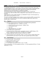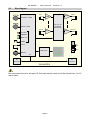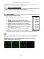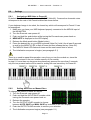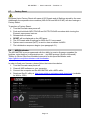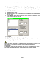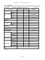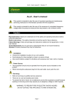
1
MS-MATRIX – User’s manual © - Revision 1.8 MS-MATRIX - User manual This symbol is intended to alert the user of important operating and maintenance (servicing) instructions in the literature provided with the equipment. This symbol is intended to alert the user of the presence of uninsulated dangerous voltage within the product’s enclosure that may present a risk of electric shock. 1 Caution Read Instructions: read and understand all of the safety and operating instructions before using this equipment. Retain Instructions: the safety instructions should be kept for future reference. Follow Warnings: follow all warnings and instructions marked on the equipment or in the user manual. Avoid Attachments: do not use tools or attachments that are not recommended by Alyseum as they may prove to be hazardous. Installation: ● Choose the installation location of your unit carefully. ● Avoid placing it in direct sunlight or close to a source of heat. ● Additionally avoid locations subject to vibrations and excessive dust, heat, cold or moisture. Servicing: Refer all servicing to qualified service personnel. There are no user-serviceable parts inside. To prevent the risk of shock, do not attempt to service this equipment yourself because opening or removing covers may expose you to dangerous voltage or other hazards. WARNING: TO PREVENT FIRE OR ELECTRIC SHOCK HAZARD, DO NOT EXPOSE THIS APPLIANCE TO RAIN OR MOISTURE. Page 1 MS-MATRIX – User’s manual © - Revision 1.8 2 Contents 1 Caution ............................................................................................................... 1 2 Contents ............................................................................................................. 2 3 What is the MS-MATRIX ? ................................................................................. 4 4 5 3.1 Features ....................................................................................................... 4 3.2 Specifications ............................................................................................... 4 3.3 Bloc diagram ................................................................................................ 5 Hardware ............................................................................................................ 6 4.1 Package Content .......................................................................................... 6 4.2 Expander Options......................................................................................... 6 4.3 Installing the MS-MATRIX ............................................................................ 6 4.4 Front Panel ................................................................................................... 7 Software ............................................................................................................. 8 5.1 Initialization Sequence.................................................................................. 8 5.2 Mode Selection............................................................................................. 8 5.3 IN / OUT Mode ............................................................................................. 8 5.4 PRESET Mode ............................................................................................. 9 5.4.1 Loading a Preset....................................................................................... 9 5.4.2 Saving a Preset......................................................................................... 9 5.4.3 Saving a Preset Automatically ................................................................ 10 5.5 MIDI / CV Mode .......................................................................................... 10 5.6 Settings ...................................................................................................... 11 5.6.1 Assigning a MIDI Note to Preset 01 ........................................................ 11 5.6.2 Setting Auto Save or Manual Save ......................................................... 11 5.7 Factory Reset ............................................................................................. 12 5.8 MIDI Bootloader.......................................................................................... 12 5.9 MS-MATRIX Editor ..................................................................................... 14 5.9.1 Matrix Editor Tab..................................................................................... 14 5.9.2 MIDI Device Selector .............................................................................. 14 5.9.3 Preset Selector ....................................................................................... 15 5.9.4 MS-MATRIX Actions ............................................................................... 15 5.9.5 File Actions ............................................................................................. 15 5.9.6 Labels ..................................................................................................... 15 5.9.7 Active-Preset Changer Tab..................................................................... 16 Page 2 MS-MATRIX – User’s manual © - Revision 1.8 6 Miscellaneous .................................................................................................. 17 6.1 Disclaimer................................................................................................... 17 6.2 Maintenance ............................................................................................... 17 6.3 Static Electricity, ESD................................................................................. 17 6.3.1 Some tips and precautions for ESD sensitive environment .................... 17 6.3.2 Standard symbols for ESD advertising ................................................... 17 6.4 Statement and Agency Compliance ........................................................... 18 6.4.1 WEEE (for EU countries) ....................................................................... 18 6.4.2 RoHS Compliance (for EU countries) .................................................... 18 6.4.3 CE (for EU countries)............................................................................. 18 6.5 Warranty and repair.................................................................................... 18 6.6 MIDI Chart .................................................................................................. 19 Page 3 MS-MATRIX – User’s manual © - Revision 1.8 3 What is the MS-MATRIX ? The Alyseum MS-MATRIX is a Eurorack module consisting of a dynamic matrix, both analog and digital in nature, which supports 16 inputs and 16 outputs. A special 256 LED display makes for a friendly and intuitive graphical user interface, with each LED representing one of the 256 points of connections available. The module accepts a variety of signals such as Gates, Clocks, CV and VCO simultaneously, while the different user configurations can be saved as user Presets in 32 locations. These Presets can be recalled manually, by a dedicated CV Input on the front panel, by MIDI (either incoming Note On or CC). The Input and Output expander mixer modules can be controlled by MIDI commands from the main unit via infra-red (IR) link. No need for additional cables which might cause ground loops or interferences! 3.1 ● ● ● ● ● 3.2 Features Specialized single Chip from Analog Device (AD75019) which guarantees: o Wide signal range: from –11 Volts to +11 Volts o Isolation between any two channel: -92dB at 1 KHz o Low distortion: 0,01% o Low noise o High bandwidth DC up to 20KHz 16 low offset input & output buffers 32 presets storage in flash memory, selectable manually, via MIDI (Note or CC), Control Voltage, or the Make Noise CTRLSEL line of modules Programmable MIDI channel number for PGM CH or NOTE. Optical hi-speed infra-red (IR) data emitter to control the slave modules MS-4VCAL and MS-4VCAR, with: Zero HF noise, Zero risk of ground loop and Zero cables. Specifications ● Front panel width: 132 mm (26HP) ● Module maximum depth: 26 mm ● Inputs jacks: 3.5 mm - ring/tip ● CV and Digital input maximum level: -11 to +11 Volts Power requirements: +12 Volts regulated at 50 mA, -12 Volts regulated at 50 mA, +5 Volts regulated at 150 mA Page 4 MS-MATRIX – User’s manual © - Revision 1.8 3.3 Bloc diagram MCU IN 1 Buffer Buffer OUT 1 OUTPUT / LOAD HV 16 x 16 Crosspoint switch array INPUT / SAVE IN 16 IN / OUT Buffer Buffer OUT 16 PRESET MIDI / CV MODE 5V 12V CV IN 12V LED CTRL MIDI IN TX IR Transmit IR Transmit MS-MATRIX Not connected source to the input 16, this input can be used only if the entries from 1 to 15 are all used. Page 5 MS-MATRIX – User’s manual © - Revision 1.8 4 Hardware 4.1 ● ● ● 4.2 ● ● 4.3 Package Content One MS-MATRIX module with Eurorack compliant front panel and power ribbon cable One plastic bag containing: o Four M3 screws o Four M3 nylon washers o Power cable Warranty & user manual access card Expander Options MS-4VCAI - Quad VCA Input module MS-4VCAO - Quad VCA Output module Installing the MS-MATRIX To install the MS-MATRIX follow these instructions carefully: ● Disconnect the Eurorack case from the main power supply by unplugging it from the wall socket! ● Never use a power supply that delivers more than a range of -12 to +12 Volts ● Make sure that the power source of your Eurorack case is able to deliver a current of o 150 mA delivered via the +5 Volt rail o 30 mA delivered via both the -12 and +12 Volt rails ● Only connect the module to a Eurorack bus board powered by a specified A-100 power supply ● Make absolutely certain that the ribbon cable has the right orientation by connecting the indicated red stripe on the negative 12 Volt side of your Eurorack case bus board ● Be advised that failure to properly plug in the power cable may result in the module malfunctioning or being destroyed as soon as the power is turned back on ● Also be advised that for modules that have been damaged by being connected to the bus board in a wrong way the warranty is void! ● Carefully place the module on an appropriately spaced spot on your Eurorack and fasten it firmly in place with the supplied screws and nylon washers. Replace any covers or blanking plates that you removed to install the module and screw them in firmly ● Reconnect the Eurorack case power cable back into the main power supply and switch the case power on ● Test out your newly installed MS-MATRIX module by following the instructions of Chapter 5.1 Initialization Sequence ● If it doesn’t seem to be working as expected, immediately disconnect the system from the mains power supply again. In this case, double-check the connections, Page 6 MS-MATRIX – User’s manual © - Revision 1.8 making completely sure that the ribbon cable is the right way round where it connects to the module and the bus. 4.4 1. 2. 3. 4. 5. 6. 7. 8. 9. 10. 11. 12. Front Panel MIDI IN port: CV jack plug: INPUT 1 – 16 jack plug: OUTPUT 1 – 16 jack plug: OUTPUT/LOAD push encoder: INPUT/SAVE push encoder: IN/OUT LED (red): PRESET LED (green): MIDI/CV LED (green): Push Button: Graphical LED display (green): IR LED emitter: The MIDI input for Preset selection via MIDI devices (DIN5) CV input for Preset selection (3,5 mm jack) The sixteen inputs of the matrix (3,5 mm jack) The sixteen outputs of the matrix (3,5 mm jack) Rotary encoder with momentary push button Rotary encoder with momentary push button When turned On it indicates that IN/OUT Mode is engaged When turned On it indicates that Preset Mode is engaged When turned On it indicates that MIDI/CV Mode is engaged Scrolls through the different Modes A LED array indicates the current connections of the matrix Transmits data to the MS-4VCAI and MS-4VCAO expanders Page 7 MS-MATRIX – User’s manual © - Revision 1.8 5 Software 5.1 Initialization Sequence 1. Turn the Eurorack case power on 2. The brand name Alyseum is displayed on the LED array for less than a second 3. The three mode LEDs flash for half a second each 4. The matrix stored in the last used Preset is loaded and displayed on the LED array. 5. A MIDI signal is sent via IR, informing slave modules that the particular Preset has been loaded. 5.2 Mode Selection Push the Mode button to select the desired mode ● No Mode (All LED Mode Off) ● IN / OUT ● PRESET ● MIDI / CV No Mode IN / OUT PRESET MIDI / CV 5.3 IN / OUT Mode To select a connection between an input and an output on the matrix: 1. Select IN/OUT Mode (see paragraph 5.2) 2. The line and column guides appear on the LED array. 3. Turn the INPUT/SAVE encoder to select a row. The selected row number corresponds to the input jack of the same number 4. Turn the OUTPUT/LOAD encoder to select a column. 5. The selected column number corresponds to the output jack of the same number To activate the selected connection push either the INPUT/SAVE or the OUTPUT/LOAD encoder until the corresponding LED is turned ON. The line and column guides disappear. To deactivate the selected connection push either the INPUT/SAVE or OUTPUT/LOAD encoder until the corresponding LED is turned OFF. The line and column guides disappear To move on to another connection, turn the INPUT/SAVE or the OUTPUT/LOAD encoder and then go to step 4 . The MS-MATRIX does NOT function as a mixer. Please refer to the expander for mixer function. While it is possible to map one input location to several output locations (and thus have the MS-MATRIX act as a multiplier), it is impossible to map several inputs to the same output. Page 8 MS-MATRIX – User’s manual © - Revision 1.8 All outputs not specifically connected to an input, are by default connected to input 16, so as to avoid interference between analog audio channels. Please do not use input 16 unless all other inputs (1-15) are already connected to an output. 5.4 PRESET Mode Presets can be loaded in several ways: manually, by the dedicated CV Input located on the front panel, by MIDI (either incoming Note On or CC), or by the Make Noise CTRLSEL line of modules. 5.4.1 Loading a Preset Loading a Preset manually is always possible regardless of the method selected by MIDI/CV Mode (see paragraph 5.5) To manually load a Preset: 1. Select PRESET Mode (see paragraph 5.2) 2. The last used Preset is recalled and its index (LOAD 01 to 32) displayed for less than a second 3. The matrix stored in the last used Preset is displayed on the LED array display. 4. Turn the OUTPUT/LOAD encoder to select a Preset location. Presets are indexed in locations between LOAD 01 and LOAD 32. Preset index is displayed for less than a second, and then the matrix stored in the selected Preset is displayed (but not loaded yet). 5. Push the OUTPUT/LOAD encoder to confirm your selection. 6. The matrix connections are set according to the selected Preset. A MIDI signal is sent informing slave modules that the particular Preset has been loaded. 5.4.2 Saving a Preset To save the current matrix connections as a Preset: 1. Select PRESET mode (see paragraph 5.2) 2. The last used Preset is recalled and its index (LOAD 01 to 32) displayed for less than a second. 3. The matrix stored in the last used Preset displayed on the LED array display. 4. Turn the INPUT/SAVE encoder to select a Preset location. Presets are indexed in locations between SAVE 01 and SAVE 32. Preset index is displayed for less than a second, and then the matrix stored in the selected Preset is displayed (but not overwritten yet). 5. Push the INPUT/SAVE encoder to confirm your selection. 6. The current matrix connections are stored to the selected Preset location. A MIDI signal is sent informing slave modules that the particular Preset has been saved. Remember to save your settings after editing a matrix. When a Preset location is already occupied by having previous matrix saved to it, the Preset mode LED will be flashing quickly while that Preset is selected in Preset Mode. Page 9 MS-MATRIX – User’s manual © - Revision 1.8 Pushing the INPUT/SAVE encoder will overwrite the current matrix connections to the specific location and the previously saved matrix will be lost. 5.4.3 Saving a Preset Automatically When Auto Save is activated (see paragraph 5.6.2) there is no need for any action in order to save a Preset as any change made is automatically saved. This means that by activating or deactivating a connection while in IN/OUT Mode you also alter the matrix saved on the specific Preset location. 5.5 MIDI / CV Mode To select the method of loading a Preset: PGM 01 1. Select MIDI/CV mode (see paragraph 5.2) 2. Turn the INPUT/SAVE encoder to select one of the five settings: (see Operation Snapshot below). PGM 16 A. PGM XX: Selects Preset by MIDI Program Change messages (PGM CH) coming from the front panel MIDI port NOTE 01 (XX = MIDI channel 1 to16) B. NOTE XX: Selects Preset by MIDI Note On messages incoming from the front panel MIDI port (XX = MIDI channel NOTE 16 1 to 16) C. CV FR: Selects Preset by CV coming from the front panel CV FRONT input labeled CV (0 to +5 Volts) D. — — : Selects Preset only manually (see paragraph __ __ 5.4.1.) 3. Push the INPUT / SAVE encoder to confirm your selection 4. Your selection has been saved as soon as the MIDI/CV Mode LED is turned Off. When one of the five MIDI/CV Mode settings has been selected any incoming activity, either from the MIDI IN input or the CV input, will be indicated by the flashing MIDI/CV Mode LED. All Preset changes due to midi or analog signals are ignored while IN/OUT Mode, PRESET Mode or MIDI/CV Mode is active. Page 10 MS-MATRIX – User’s manual © - Revision 1.8 5.6 Settings 5.6.1 Assigning a MIDI Note to Preset 01 By default Preset 01 corresponds to key C3 (MIDI Note 48). Consecutive chromatic notes correspond to the rest of the Preset locations as shown below. If your keyboard range is too short, the lowest key which will correspond to Preset 01 can be reassigned: 1. Make sure you have your MIDI keyboard properly connected to the MIDI IN input of the MS-MATRIX 2. Turn the Eurorack case power off. 3. Push and hold the push button while turning the Eurorack case power back on. 4. NEW NOTE is displayed on the LED display 5. Release the Mode push button (Mode button) 6. Press the desired key on your MIDI keyboard (Note On), hold it for at least 5 seconds or wait for the MIDI/CV LED to flash 4 times and then release the key (Note Off). 7. The MIDI/CV Mode LED flashes 4 times and the new lowest Note is saved. 8. The initialization sequence is begins (see paragraph 5.1) There is no need to repeat this operation every time you turn the module on, since the lowest Note is stored in the non-volatile memory of the module. In step 6, if more than one keys are simoultaneously pressed for more than 5 seconds, only the one pressed earlier will be used for setting the new lowest key for Preset 01. 5.6.2 Setting Auto Save or Manual Save To change the method Presets are saved: 1. Turn the Eurorack case power off. 2. Push and hold the INPUT/SAVE encoder while turning the Eurorack case power back on. 3. Release the encoder. 4. Turn the OUTPUT/LOAD encoder to choose between AUTO SAVE and MAN. SAVE as indicated on the LED display. 5. Push the OUTPUT/LOAD encoder to confirm your selection. 6. The Initialization sequence begins (see paragraph 5.1) Page 11 MS-MATRIX – User’s manual © - Revision 1.8 5.7 Factory Reset Be aware that a Factory Reset will erase all 32 Presets and all Settings stored by the user. Additionally the expander mixer modules (MS-4VCAI and MS-4VCAO) will also undergo a Factory Reset. To perform a Factory Reset: 1. Turn the Eurorack case power off. 2. Push and hold both INPUT/SAVE and OUTPUT/LOAD encoders while turning the Eurorack case power back on. 3. Release both encoders. 4. RESET will be displayed on the LED array. 5. The 32 Presets and all settings for MIDI and CV are erased. 6. System reset command (0xFF) is sent to slave modules via MIDI. 7. The initialization sequence begins (see paragraph 5.1). 5.8 MIDI Bootloader The MS-MATRIX is pre-programmed with the ability to receive firmware upgrades (for bugfixes, extra features, customizations etc...) via MIDI protocol (SysEx commands). Thanks to Olivier Gillet from Mutable Instrument for his open Bootloader code: https://github.com/pichenettes/avr-midi-bootloader. In order to flash new firmware, please follow the instructions below: 1. Turn the Eurorack case power off. 2. Close all MIDI software on your computer. 3. Connect the computer and the MS-MATRIX with a MIDI cable. 4. Download Sys Ex utility at http://www.elektron.se/support-and-downloads (available for WIN or OSX). Page 12 MS-MATRIX – User’s manual © - Revision 1.8 5. Press and hold the BOOT button, while turning the Eurorack case power back on. The BOOT button is located behind the small hole in MS-MATRIX front panel – left from the mode LED, and can be pressed using a thin, long object like, for example, a toothpick. 6. All the LEDs flash 3 times. 7. Release the BOOT button. 8. Open the Elektron C6 Sys Ex utility software, click Load, find the new firmware file and click Open. 9. Click Configure, select a MIDI Out port, set 200mS for Delay in the textbox, select x1 for Turbo limit field and click OK. 10. Click Send. 11. The LEDs first flash one after the other, then all together fast. 12. Wait until sending is complete. All the LEDs flash 4 times, and the module reboots to normal operating mode with new firmware. Please note that for the software to be able to send the MIDI commands successfully, no other software or Active Sensing message should be using the MIDI device simultaneously. All parameters (lowest note, last used preset, last used midi channel or cv input, preset save mode) are reset and all Presets are erased during new firmware flashing. Page 13 MS-MATRIX – User’s manual © - Revision 1.8 5.9 MS-MATRIX Editor The MS-MATRIX Editor is an application that provides an easy and fast interface to the MS-MATRIX functionalities. It works on Windows and Mac OSX, and it’s free to download from the Alyseum website (http://www.alyseum.com/downloads). The MS-MATRIX Editor is a standalone/portable executable, so there is no installation process. Once you download it, all you have to do is open it, so you can use it. Depending on your computer’s specifications, it could take a few seconds to load, as it has been compressed, in order to save space. Once you have opened the MS-MATRIX Editor, you are presented with a screen such as the following: 5.9.1 Matrix Editor Tab This is the default active tab when opening the application. It consists of a 16x16 matrix with round buttons, that have a toggling functionality, as well as a “Clear Matrix” button, for easy matrix clearing. 5.9.2 MIDI Device Selector All available MIDI devices connected to your computer will be listed in the dropdown field “MIDI Device Selector”. Please choose the one connected to your MS-MATRIX. In case another device is selected (for example, Microsoft GS Wavetable Synth virtual interface), the MS-MATRIX Editor could automatically exit during MIDI transmission. Page 14 MS-MATRIX – User’s manual © - Revision 1.8 5.9.3 Preset Selector The “Preset Selector” is a dropdown list of 32 presets. When a Preset is selected, it is loaded onto the matrix, in the center of the screen. Also, the “Save Current Preset” button uses the Preset selected in this list (see 5.9. Save Current Preset). 5.9.4 MS-MATRIX Actions Save All Presets: All Presets are saved to the MS-MATRIX. The active I/O connections are not changed. Save Current Preset: The selected Preset (see 5.9.3 Preset Selector) is saved to the MSMATRIX. The active I/O connections are not changed. 5.9.5 File Actions Load Presets and Labels: Select a file previously saved by using the “Save Presets and Labels” button (see 5.9.5 Save Presets and Labels), so that its contents are loaded into the MS-MATRIX Editor. In case you have edited Presets or Labels without having saved the changes, you are presented with a verification for overwriting the existing Presets and Labels with the imported ones. Save Presets and Labels: Download a file containing all Presets and Labels currently in the MS-MATRIX Editor. You can afterwards load it (see 5.9.5 Load Presets and Labels) and continue working where you left off. 5.9.6 Labels Output and Input Labels are used to easily identify Outputs and Inputs, respectively. They appear when hovering the mouse over the matrix. By clicking on a label row, a popup appears, providing the ability to change that label, as seen in the image on the right. Page 15 MS-MATRIX – User’s manual © - Revision 1.8 5.9.7 Active-Preset Changer Tab The Active-Preset Changer Tab can be used to load a Preset from the MS-MATRIXs EEPROM memory to the active switch matrix (see 5.4.1 Loading a Preset). After selecting the correct channel – the one that the MS-MATRIX is configured to receive PGM Change Messages on (see 5.5 MIDI / CV Mode) – you just press the button corresponding to the Preset you want to load and the matrix connections are set according to the selected Preset. In case the MIDI Device Selector is empty, although there are MIDI-output devices connected to your computer, please re-open the MS-MATRIX Editor with Administrator permissions (right click the executable and choose “Run as Administrator”). Page 16 MS-MATRIX – User’s manual © - Revision 1.8 6 6.1 Miscellaneous Disclaimer All rights reserved. Reproduction in whole or part of this document is prohibited without the express permission of Alyseum. © 2011-2015 Alyseum The information and specifications described in this manual are subject to change without prior notice Throughout this manual, trademarked names might be used. We state herein that we are using the name to the benefit of the trademark owner, with no intention of infringement. 6.2 Maintenance Switch Off the power before maintenance. Do not attempt to clean the module with chemical solvents (thinner, benzene or alcohol) as this might damage the finish. Use only a clean, dry cloth. 6.3 Static Electricity, ESD Electrostatic discharge (ESD) can cause malfunction and/or damage to electronic devices if discharged into the module. Despite Alyseum products having built-in protections against ESD, voltages might build up at levels that could harm your equipment. 6.3.1 Some tips and precautions for ESD sensitive environment ● Make sure to discharge any built-up static electricity from yourself and your devices before touching or connecting one device to another ● Ground yourself by touching an earth grounded metal surface before handling your module and other equipments. ● For fixed installations, place the module in a grounded metallic rack. ● Ensure air relative humidity is minimum 60%. ● Install ESD specific prevention items, such as grounding mats. ● Reduce movement speed when handling or (dis)connecting devices ● Avoid carpet or other synthetic flooring. 6.3.2 Standard symbols for ESD advertising Page 17 MS-MATRIX – User’s manual © - Revision 1.8 6.4 Statement and Agency Compliance 6.4.1 WEEE (for EU countries) Waste Electrical and Electronic Equipment (Directive 2002/96/EC) (Applicable for E.U. Customers or others countries with separate collection systems) 1. This marking shown on the product or its literature, indicates that it should not be disposed with other household wastes at the end of its working life. 2. To prevent possible harm to the environment or human health from uncontrolled waste disposal, please separate this from other types of wastes and recycle it responsibly to promote the sustainable reuse of material resources. 3. Household users should contact either the retailer where they purchased this product, or their local government office, for details of where and how they can take this item for environmentally safe recycling. 6.4.2 RoHS Compliance (for EU countries) Alyseum products comply with the European Union restriction of the use of certain hazardous substances in electronics equipment, (RoHS directive 2002/95/EC) The RoHS directive prohibits the sale of certain electronic equipment containing some hazardous substances such as Mercury, Lead, Cadmium, Hexavalent chromium and certain Flame-retardants (PBB & PBDE) in the European Union. http://eur-lex.europa.eu/LexUriServ/LexUriServ.do?uri=CELEX:32002L0095:EN:HTML 6.4.3 CE (for EU countries) Alyseum products comply with the requirements of European Directive 89/336/EC. 6.5 Warranty and repair Alyseum warrants to you, the original purchaser, that each of its products will be free from defects in materials and workmanship for a period of two years from the date of purchase. This warranty does not apply to any products which have been repaired or altered by other than repair personnel authorized by Alyseum, or which have been subject to ESD, moisture, abuse, accident or improper installation and use. Alyseum assumes no liability as a consequence of such events under the terms of this Warranty. Please consult your dealer for more details. Page 18 MS-MATRIX – User’s manual © - Revision 1.8 6.6 MIDI Chart MS-MATRIX MIDI IMPLEMENTATION CHART ver.1.0. Function 2013-08-07 Transmitted Recognized Remarks Default -- 1-16 Changed -- O Default -- O Messages -- O Altered -- O Note Number -- X Velocity -- O Keys -- O Channels -- O Pitch Bend -- O Control Change -- O Prog. Change True# -- X 1-32 System exclusive -- X Firmware upgrade & Editor Song Position -- O Song Select -- O Tune Request -- O Clock -- O Commands -- O Local On/Off -- O All Notes Off -- O Active Sensing -- O System Reset -- O Basic Channel Mode not applicable not applicable After Touch System Common System Realtime Aux Messages Notes X= yes, O = no Page 19