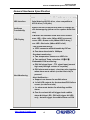
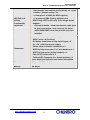
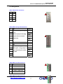
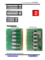
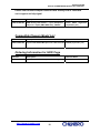
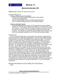
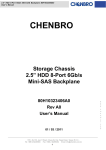
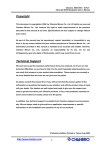
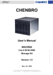
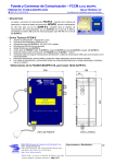
1
Chenbro SR106
6-Ports SAS/SATAII Backplane User’s Manual
6 Ports SAS/SATAII
Backplane
User Manual Rev. 1.0
Supplier :
Description :
Chenbro Micom Co., Ltd .
6 Ports SAS/SATAII Backplane
Chassis :
SR106
Part No :
80H102106-004 Rev. A1
http://www.chenbro.com
1
Chenbro SR106
6-Ports SAS/SATAII Backplane User’s Manual
Copyright
This document is copyrighted, 2004, by Chenbro Micom Co., Ltd. All rights are reserved.
Chenbro Micom Co., Ltd. reserves the right to make improvements to the products
described in this manual at any time. Specifications are thus subject to change without
prior notice.
No part of this manual may be reproduced, copied, translated, or transmitted in any
form or by any means without the prior written permission of Chenbro Micom Co., Ltd.
Information provided in this manual is intended to be accurate and reliable. However,
Chenbro Micom Co., Ltd., assumes no responsibility for its use, nor for any
infringements upon the rights of third parties, which may result from its use.
Technical Support
We want you to get the maximum performance from your products. So if you run into
technical difficulties, we are here to help. For the most frequently asked questions, you
can easily find answers in your product documentation. These answers are normally a
lot more detailed than the ones we can give over the phone.
So please consult this manual first. If you still cannot find the answer, gather all the
information or questions that apply to your problem, and with the product close at hand,
call your dealer. Our dealers are well trained and ready to give you the support you
need to get the most from your Chenbro products. In fact, most problems reported are
minor and are able to be easily solved over the phone.
In addition, free technical support is available from Chenbro engineers every business
day. We are always ready to give advice on application requirements or specific
information on the installation and operation of any of our products.
http://www.chenbro.com
2
Chenbro SR106
6-Ports SAS/SATAII Backplane User’s Manual
Category
1
General Hard-Ware Specification
2 Backplane Layout
3 Backplane Photo
4 Backplane Cable Information
5 Backplane Ordering Information
http://www.chenbro.com
3
Chenbro SR106
6-Ports SAS/SATAII Backplane User’s Manual
General Hardware Specification
Host Interface
SAS/SATA II interfaces(single path)
HDD Interface
HDD connector (power + drive : 7+7+15 pins) for SAS
(Serial Attached SCSI) drive , also compatible to
SATA II drive (7+15 pins)
Hot-Swap
Functionality
Support inrush current control and Pre Charge for
drive hot-swapping (allow on line replace Hard Disk
Drive)
LED Display
On Board LED indicates Hard Disk Drive status:
Power LED – Blue color (When HDD is present )
Access LED –Green color (When HDD is busy )
Error LED –Red color (When HDD is fail )
1. Fan speed monitoring :
a. 3P3C connector disable/enable by DIP sw.
b. Fan alarm threshold is 2000rpm
2. Overheat monitoring :
a. Two temperature sensors on HDD site
b. Two optional Temp. selection :55℃/65℃
Alert Monitoring
3.Redundant PSU monitoring :
a. PSU fail signal input : TTL signal input (normal
high and pull-high resistor is required)
b .PSU alarm mute output : short two pins together
when alarm mute switch (on the front site) is
pressed
4. Alert Notification :
a. Support one buzzer for audible alarm
b. 1× fail LED outputs for fan/overheat/PSU failure
events (on the front site)
c. 1 x alarm mute button for disabling audible
alarm
d. Fan & overheat fail will trigger both audible
alarm & failure LED , PSU will trigger fail LED
only , but will trigger its audible alarm on PSU
http://www.chenbro.com
4
Chenbro SR106
6-Ports SAS/SATAII Backplane User’s Manual
HDD Fail and
Activity
Functionality
supported
1. HDD activity LED source is selected by 2 x 7 pins
headers “jumper setting” for :
a. from pin 11 of HDD (As HDD support )
b. or external HBA Card by adapter wire
2. HDD Faulty LED is driven by 2 pcs single 4 pins
headers :
Discrete solution : need one discrete cable (port
to port) connection , only reserves for those
which HBA RAID cards can provide such this
interface
Connectors
1. SAS(15+7+7 pins) x 6 (for HDD )
2. SAS(7 pins) x 6 (for Host)
3. DC power connectors in big 4-pin D-type x 2
for +5V, +12V from power supply
4. Power alarm and mute connectors x 2
5. HDD Activity connector (2 x 7 pins headers) x 1
6. HDD Fail connector (4 pins headers) x 2
7. Fan (3P3C) connectors x 2
8. Failure LED Connector (2 x 4 pins headers) x 1
Above detail pin definition see below information
Dimension
185(L) x 1130(W) x 2.4(H) mm
Material
FR4 4layer
http://www.chenbro.com
5
Chenbro SR106
6-Ports SAS/SATAII Backplane User’s Manual
Backplane Layout
Backplane View
CN11
CN13
CN23
CN33
CN1
CN2
CN21
JF2
JF1
JM1
JP1
CN31
CN7
CN43
CN41
SW1
CN51
CN53
CN4
CN63
CN61
CN3
CN5
Backplane Connector
(1) [CN11/CN21/CN31/CN41/CN51/CN61] : 29-pins SAS HDD Connector
(2) [CN13/CN23/CN33/CN43/CN53/CN63] : 7-pins SAS/SATAII Host Connector
(3) [CN1 /CN2] : Power Connectors
(4) [CN3] : External HDD Activity LED Connector (from RAID Card)
(5) [CN4/CN5] : Discrete HDD Failure LED Connector (from RAID Card)
(6) [CN7] : Fan/PWR/Temp. Failure LED Connector (to Front Panel LED Display)
(7) [JF1/JF2] : Fan Connectors
(8) [SW1] : Functionality / Mode Setting
(9) [JP1] : Power Failure Input (From Redundant Power Supply)
(10) [JM1] : Power Failure Alarm Mute Output (to Redundant Power Supply)
http://www.chenbro.com
6
Chenbro SR106
6-Ports SAS/SATAII Backplane User’s Manual
Pin Assignment
[CN1 /CN2] Power Connector
Pin
Def.
1
+5V
2
GND
3
GND
4
+12V
[CN3] HDD Activity LED Connector
Pin
Def.
1
External Activity LED Signal CN11
3
Input
CN21
5
(Remove jumper then plug
CN31
7
adapter wire to connect
CN41
RAID card)
9
HDD No.
CN51
CN61
11
13
Key Pin
14
N/A
1&2
As HDD can support activity CN11
3&4
LED signal , using jumper to CN21
5&6
close each two pins shown
CN31
7&8
left side
CN41
9 & 10
CN51
11&12
CN61
[CN4] HDD Fail LED Connector
Pin
Def.
1
Fail LED for HDD CN11
2
Fail LED for HDD CN21
3
Fail LED for HDD CN31
4
Fail LED for HDD CN41
[CN5] HDD Fail LED Connector
http://www.chenbro.com
7
Chenbro SR106
6-Ports SAS/SATAII Backplane User’s Manual
Pin
Def.
1
Fail LED for HDD CN51
2
Fail LED for HDD CN61
3
N/A
4
N/A
[CN7] Fan/PWR/Temp. Failure LED Connector
Pin
Def.
1
Fan Failure LED +
2
Fan Failure LED -
3
Power Failure LED +
4
Power Failure LED -
5
Alarm Mute Switch +
6
Alarm Mute Switch -
7
N/A
8
Key Pin
[JF1 /JF2] Fan Connector
Pin
Def.
1
GND
2
+12V
3
Sensor
[JP1] Redundant PSU Module Fail Connector
Pin
Def.
1
GND
2
Power Fail Signal (TTL Active Low)
[JM1] Alarm Mute Connector
Pin
Def.
1
Switch -
2
Switch +
[SW1 (1)] DIP Switch Function
http://www.chenbro.com
8
Chenbro SR106
6-Ports SAS/SATAII Backplane User’s Manual
Fan1 Detection Enable/Disable
SW1-1
Enable
ON
Doisable
OFF
[SW1 (2)]
Fan2 Detection Enable/Disable
SW1-2
Enable
ON
Doisable
OFF
[SW1 (3)]
Temperature Setting
SW1-3
65 Degree C
ON
55 Degree C
OFF
Backplane Photo
HDD Side View
Host Side View
Backplane Cable Information
http://www.chenbro.com
9
Chenbro SR106
6-Ports SAS/SATAII Backplane User’s Manual
Please refer to below adapter cable for HDD activity LED in case HDD
can’t support activity signal
Part No.
Description
Compatible with HBA RAID
26H112106-001
HDD Activity LED Cable 1 x 7 pins (backplane
Areca , 3Ware , High Point
site) to 2 x 4 pins (HBA RAID site) , 600mm
(required 1 pcs)
Compatible Chassis Model List
Part No.
Description
Chassis Model
80H102106-004
6 ports SAS/SATAII Backplane for HDD fail LED
SR106 (required 1 pcs)
Ordering Information for HDD Cage
Part No.
Description
Chassis Model
84H220910-045
6 ports SAS/SATAII Backplane Assembly (BK)
SR106
http://www.chenbro.com
10