1
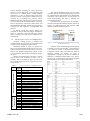
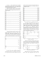
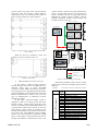
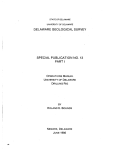
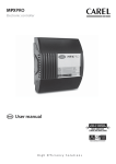
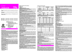
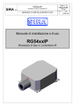
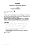
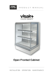
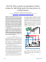
PLC/SCADA systems in automation control
design for individual quick freezing process in
cooling tunnels
Goran Jagetić, Marko Habazin, Tomislav Špoljarić
University of Applied Sciences - Department of Electrical Engineering, Zagreb, Croatia
[email protected], [email protected], [email protected]
1896
Compressor
Evaporator temp. probe
Heaters
Fans
Simple cooling process [1] is thermal process
used in refrigeration systems for maintaining room
temperature via temperature regulator and at least
one temperature probe. Temperature is achieved and
maintained by correct switching of refrigeration
system elements – compressor, electromagnetic
valve, evaporator fans and condenser fans. This
basic type of operation is not time-dependent and is
most commonly used in small scale cooling systems
with required temperature above 0°C.
When required room temperature needs to be
maintained below 0°C, refrigeration system needs
defrosting for evaporator section due to icing. This
is done by switching the electrical heaters that need
to be inserted into the evaporator section or, when
electrical defrost is not available, by defrosting with
hot gas. Defrosting element operation (heater or
valve) is done separately from other refrigeration
system elements (compressor, fans, etc.).
When defrost is needed, control design takes
form of one cycle regulation [1] thus making it time
dependent. A repeating cycle of operation consists of
EM valve
INTRODUCTION
Condenser (fans)
Regulator
I.
two periods of operation: refrigeration period and
defrosting period. Refrigeration period is longer and
in it refrigeration elements (compressor, condenser
and evaporator fans) are switched according to room
temperature probe/probes. Defrosting period is much
shorter and in it defrosting elements (electrical
heaters/hot gas valve) are switched according to
evaporator temperature probe or by time (offdelayed timer function of a regulator). Fig. 1 shows
simplified block diagram of a small scale
refrigeration system operated by one-cycle
regulation (refrigeration with defrost).
Room temp. probe
ABSTRACT - Individual quick freezing process is a
complex cooling process that takes place in cooling
tunnels and is used for dynamic thermal processing of
certain type of goods. Type of goods and temperature
of goods that needs to be achieved over specific time in
cooling tunnel determine the complexity of cooling
process. Complex cooling process is therefore divided
into two types of regulation. Temperature regulation,
the inferior type, is used for control of the cooling and
defrosting parts of the system according to predefined
room temperature. Superior time-cycle regulation is
used to control various cycles of operation by defining
its time frames. These cycles together form a period of
time in which the cooling system is appropriately used
for goods' freezing.
This paper describes further development in
automation control design for complex cooling process
in cooling tunnels. This design includes selection of
appropriate control devices (temperature/pressure
regulators, PLC device, HMI/SCADA), definition of
LADDER program solution for dynamic time-cycle
control, connection and configuration of HMI/SCADA
system used for defining the number/duration of time
cycles of cooling and defrosting operations and
monitoring the system conditions.
Evaporator
Cold room
Figure 1. Block diagram of a simple cooling process
On a fig. 2 a time flow diagram of a simple
cooling process is shown with one cycle control
design (refrigeration with defrost period). A
repeating time cycle duration is described with
simple equation:
𝑇𝑐 = 𝑇𝑟 + 𝑇𝑑 ,
(1)
MIPRO 2015/SP
durations, and three defrost periods of same
duration. Processing time is defined with 𝑇𝑝 :
𝑇𝑝 = 𝑇𝑟1 + 𝑇𝑟2 + 𝑇𝑟3 + 3 ∙ 𝑇𝑑 ,
Tr
time
Td
Tc
Tc
Tc
off
Tr1
Tc1
Tr2
Tc2
Tr3
time
Td
off
(2)
on
Td
on
Td
process state
process state
where 𝑇𝑟 is a refrigeration period duration and 𝑇𝑑 is
a defrost period duration. When refrigeration process
is active, temperature regulation according to room
temperature probe is active. When defrost process is
active, temperature regulation according to
evaporator temperature probe is active.
Tc3
Tp
refrigeration process state
defrost process state
refrigeration process state
defrost process state
Figure 2. Time flow diagram of a simple cooling process
The complexity of a described control system
may increase in larger cooling systems by adding
also the pressure control in suction line (for
sequential switching control of the compressors in a
multiset) and discharge line (sequential switching
control of condenser fans). Most of today’s
temperature regulators have a two cycle control,
which also increases the complexity by defining
durations of two different refrigeration periods,
while defrost duration is the same in each cycle, but
is also user defined. All these additions still make the
cooling process simple.
II.
COMPLEX COOLING PROCESS AND
INDIVIDUAL QUICK FREEZING
When defining complex cooling process, one
needs to take into account that room temperature is
not the main parameter. Room temperature is
intermediary parameter for achieving the main
parameter - temperature of goods that needs to be
achieved over time. This type of processing certain
type of goods requires specific definition of time
cycles involved in process [3]. By specific definition
it is assumed that each cycle has its duration defined
by end user. It means that each operation period,
whether it is refrigeration or defrost period, has also
its duration defined in each of the cycles. A number
of cycles is also defined by end user.
Because there are a lot of types of goods that
can be cooled or frozen over time [5], control system
design for one system needs to have a possibility for
end user to define number of operating cycles and
various durations of that cycles, thus making it
possible for one system to process different type of
goods. This type of design makes the system timedependent, which requires more than one control
device to maintain the process on a desired level of
efficiency.
On fig. 3 a time flow diagram of one such
complex cooling process is shown. This process
consists of three refrigeration periods of different
MIPRO 2015/SP
Figure 3. Time flow diagram of a three-cycle complex cooling
process
Processing time is a duration of a whole process
and it can be repeated. But in individual quick
freezing it is a duration of a freezing process of
goods, therefore it is not repeated until the next
goods’ exchange.
There is a possibility for defrost and
refrigeration elements of a system to act at the same
time for a brief moment when system goes from one
state to another. That may be unwanted in larger
systems from perspective of rational electric energy
consumption and unwanted protective elements’
switching states. In that case pause periods are
introduced. Pause periods maintain the system
inoperative for short period (about 5 to 10 seconds)
in order the switching to be done properly.
With this in mind, processing time for 𝑛
number of cycles can be generally described as:
𝑛
𝑇𝑝 = ∑(𝑇𝑝𝑟,𝑖 + 𝑇𝑟,𝑖 + 𝑇𝑝𝑑,𝑖 + 𝑇𝑑,𝑖 ),
(3)
𝑖=1
where for i-th cycle terms are:
- 𝑇𝑟,𝑖 – refrigeration period,
- 𝑇𝑑,𝑖 – defrost period,
- 𝑇𝑝𝑟,𝑖 – pause period before refrigeration,
- 𝑇𝑝𝑑,𝑖 – pause period before defrost.
Complex cooling process may be implemented
in control design of a small scale refrigeration
system (temperature control only with switching of
compressors and fans), as well as in larger scale
refrigeration systems’ control designs with pressure
and temperature control. One such design is
described in this paper. This proposed design is
implemented to work with large scale refrigeration
system in a freezing tunnel. Cooling process that
takes place in a tunnel is also known as individual
quick freezing.
Individual quick freezing is a refrigeration
process of a complex nature that manages predefined
1897
Compressor 2
Condenser 1 fans
AUTOMATION CONTROL DESIGN OF A
FREEZING TUNNEL
Condenser 2 fans
TEX valve
Fans
Heaters
EM Valve
TEX valve
Fans
Heaters
Evaporator 2
regulator device
Compressor and condenser Control
EM Valve
Devices used in IQF control design can be
separated in two groups – devices used for time
regulation and devices used for temperature/pressure
regulation. Devices used for time regulation are PLC
and SCADA/HMI devices, and for temperature and
pressure regulation are used various types of specific
microcontroller devices.
Freezing tunnel described in this paper has a
carrying capacity of 30 tons of different types of
fresh fish. Cooling system for that freezing tunnel
has two screw type compressors, two evaporators
(three fans each) and two condensers (three fans
each). Compressor motors are operated by part
winding start contactor combination, and all fans are
operated by frequency converters. For time
regulation Eaton's EASY® relay device Easy800
with additional analog I/O module and XV touch
panel is chosen. For temperature/pressure regulation
chosen
devices
are:
Carel’s
pRACK®
microcontroller device for compressor and
condenser control and MPXpro® microcontroller
device for evaporator, electromagnetic and
thermoexpansion valve operation.
Compressor control operates according to
suction pressure level, temperature and pressure of
oil in compressor and cooling medium temperature.
Condenser control operates according to discharge
pressure level. Since the pRack device manages
compressor, the only signal needed is digital input
for start/stop. According to that signal and to several
1898
Compressor 1
Evaporator 1
regulator device
III.
probes inside the compressor, the pRack device
manages the switching of the compressor.
Evaporator control with MPXpro® operates
according to inlet and outlet temperature of the
evaporator during refrigeration period. In defrost
period electric heaters are switched according to
evaporator temperature probe. MPXpro ® controller
manages also the opening of electromagnetic valve
and sequential opening of the thermoexpansion
valve.
Compressor/condenser
microcontroller device
type of goods. Generally, the term or its abbreviation
IQF relates to fast freezing process of solid foods
such as various types of vegetables, meat, fish or
fruit while trying to preserve virtually most of the
properties of the parent foodstuffs. A great and fast
reduction in room/tunnel temperature reduces
rapidly the temperature of goods. This halts the
activities of microorganisms that cause goods to
deteriorate and generate toxic substances.
Additionally, the enzymatic and biochemical
reactions of the digestive enzymes which are found
in all living tissues and whose activities continue
even after death are also greatly reduced. In goods
frozen with IQF process there is no clumping
together and there aren’t any pieces of grains. Goods
remain individual separate pieces. Hence the term
“individual” [6].
There are several types of individual quick
freezing processes [4], and the one described in this
paper is called individual quick freezing in air-blast
freezing tunnels. The goods intended to be frozen are
placed on trays. These trays are placed inside the
tunnel, where freezing process takes place for a
specified amount of time. Afterwards, the packages
are removed and usually taken to cold rooms
intended for storage.
Freezing tunnel
Evaporator Control
Figure 4.
Simplified temperature/pressure control design for
individual quick freezing process example
Time cycle control operates according to initial
values of number of cycles and duration of cycles
entered by end user. This provides desired variability
in defining the parameters of processing time by end
user. With this the process becomes dependable on
goods’ type and desired quality of freezing process.
When refrigeration period is active, every
refrigeration element of the system works according
to its regulator. Compressor is active if pressure
MIPRO 2015/SP
control demands switching on, and if protective
devices are not in fault mode: if oil temperature and
pressure are in defined limits, cooling medium
temperature is also in defined limits and motor
protective switch is not tripped. Condenser fans are
switched on if discharge line pressure control
demands activation and if protective devices are not
are not in fault mode. In similar fashion, evaporator
fans are operated by evaporator control device and
its predefined temperature. All fans have a frequency
converters for fine regulation of temperature and
pressure.
In defrost period only electric heaters are
switched on. This is done according to temperature
probe in evaporator connected evaporator control
device. In pause period all system components are
switched off.
IV.
PROGRAM SOLUTION WITH LADDER LOGIC
Complex cooling process is defined with
variable number of cycles. Each cycle is defined with
sequence pause-refrigeration-pause-defrost.
Minimum number of cycles in a process are
three cycles and maximum number are seven cycles.
Defrost and pause period are the same for all cycles
and are user defined. Refrigeration period in each
cycle is separately defined after selecting the number
of cycles.
Before programming the system for a cooling
purpose starts, it is necessary to make a list of
variables. The list includes the physical and virtual
I/O variables used later in the program and, and is
shown in table 1.
TABLE I.
EASY 822-DC-TCX (Main base)
Device
EASY 411-DC-ME
(Analog module)
The code programming of the process is done
in EASY Soft-Pro 6 software package [2]. It is used
for communication setup, definition of variables and
writing the code of the process. For the purpose of
easier understanding, the code is sampled into
several main sections.
Communication protocol known as easyNET ®
network (serial interface RS232) has been chosen for
purpose of sending/receiving data between HMI
interface (end user) and PLC device.
Figure 5. Hardware selection for freezing tunnel project design
in easySOFT pro v6.9
First part of the circuit diagram includes getting
a number of cycles from easyNET® and transferring
it to a memory location in easy822 (block GT01).
Comparator blocks CP01 and CP02 are used for
checking whether the number of cycles is
appropriately selected. If the check condition is
fulfilled, a conditional marker M10 is set. This is
shown on fig. 6. Based on the user input the program
takes number of cycles from the SCADA.
LIST OF VARIABLES IN LADDER PROGRAM
I/O
signal
I1
I2
I3
I4
I5
I6
I7
I8
I9
I10
I11
I12
Q1
Q2
Q3
Q4
QA1
AI1
AI2
AI3
AI4
AI5
AI6
AO1
AO2
MIPRO 2015/SP
Name
Local start/stop
Local/remote
Compressor 1 active
Comp. 1 motor protection fault
Comp. 1 oil protection fault
Evaporator 1 fan mot. prot. fault
Condenser 1 fan mot. prot. fault
Compressor 2 active
Comp. 2 motor protection fault
Comp. 2 oil protection fault
Evaporator 2 fan mot. prot. fault
Condenser 2 fan mot. prot. fault
Refrigeration period activation
Defrost period activation
Pause period activation
End of process
Speed reference - evaporator fans
Evaporators’ inlet temperature
Evaporators’ outlet temperature
Suction line pressure
Discharge line pressure
Actual evaporator fan speed
Actual condenser fan speed
Speed reference - condenser fans
(Optional for compressor speed ref.)
Figure 6. Program section 1 – acquirring a number of cycles
Figure 7. Program section 2 – acquirring a duration of cycles
1899
On fig. 7 a data acquisition from SCADA
(GT03-GT08 function blocks) concerning duration
of refrigeration periods in each cycle, as well as fixed
defrost and pause periods, is shown.
Digital input data acquisition is done by putting
bit values to easyNET® network (blocks 4SN01 4SN10) according to digital input states (I03-I12), as
shown on fig. 8.
memory location where GT block put the duration of
refrigeration and transfers it to a memory location of
a refrigeration timer.
Figure 10. Program section 5 – refrigeration time transfer
Figure 8. Program section 3 – digital input acquisition
User input on SCADA determines the start of
the process (4RN01 contact). It is also possible to
start the process manually from the electronic
cabinet using the 0-1 switch on the door of the
cabinet. Start is defined with rising edge marker M05
that is enabled on two additional conditions:
refrigeration times for first three cycles have been set
(M06) and defrost and pause periods have been set
along with number of cycles (M07). Also, finishing
the process depends on value in counter of cycles
(C01) or local switch position (I01).
Analog input data acquisition is done by 100ms
sample flashing timer. Each time a timer contact
makes/breaks, certain data is transferred via "put
value to NET" block (PT01-PT06) from input to
easyNET® memory location in form of variable MW
(marker word with 16bit length), as shown on fig. 9.
Figure 11. Program section 6 – conditions for starting and
finishing of the process
Starting and repeating condition of the process
is shown on fig. 12. Timer starts counting on a falling
edge of a pulse given by starting (M05) or repeating
cycle marker (M09). In this instance a counter C01
counts up.
Figure 9. Program section 4 – analog input acquisition
In each cycle, data of different refrigeration
period duration needs to be transferred. This is done
by using data block which transfers data from
1900
Figure 12. Program section 7 – starting the first timer of the
process and repeating the cycle
When timer T01 is done with counting, similar
process starts with refrigeration timer T02. This
MIPRO 2015/SP
process repeats with pause timer T03 and defrost
timer T04. After T04 is done, a marker M09 for
repeating the cycle is set and the process repeats in
next cycle if a counter C01 contact allows it.
cable is used for connection of a panel and first PLC
device. All three PLC devices are connected via
Eaton’s easyNET® network. A program for selected
HMI device is made in Eaton’s Galileo® software
package. Described cooling system design with
SCADA is shown on fig. 15.
XV Touch Panel
HMI/SCADA
EASY 822-DC-TCX + EASY 411-DC-ME
Tunnel 3 control
PLC 3 – TUNNEL 3
EASY 822-DC-TCX + EASY 411-DC-ME
Tunnel 2 control
PLC 2 – TUNNEL 2
PLC 1 – TUNNEL 1
EASY 822-DC-TCX + EASY 411-DC-ME
Figure 13. Program section 8 – pause, refrigeration and defrost
timers counting
When the process is finished, a timer and
counter are reset, as is shown on fig. 14.
Evaporator control
Suction
line probe
Compressor/condenser control
Room
temperature
probes
Discharge
line probe
Tunnel 1 control
Type of signals:
RS 232 serial
easyNET®
Analog / digital signals
Figure 14. Program section 9 – reset of timers and counter upon
completion of the process
HMI / SCADA SYSTEM CONNECTION
In this section, a RS232 serial connection
between Easy822 PLC device and HMI device is
observed. Other ways to ensure PLC-HMI
connection include RS485 and Ethernet protocols.
This cooling process is designed for general purpose
and with minimum cost and primarily for that reason
RS232 communication is chosen. Also, with this
type of communication no additional converter
modules are needed.
In this paper, proposed SCADA system is
designed to work in a cooling system with three
freezing tunnels. Control design with three PLC
devices is selected to show the modular behavior of
a proposed three tunnel control system. In this case
each tunnel’s control system is presented as one
module of that design. Every tunnel is controlled by
one EASY relay with additional analog module.
Eaton’s XV-152 touch panel is selected as a HMI
device. Touch panel is connected with PLC devices
through serial RS232 communication cable. This
MIPRO 2015/SP
Data used by SCADA system consists of input
signals listed in table II and output signals listed in
table III.
TABLE II.
Device
XV-152 Touch panel
V.
Figure 15. Observed cooling system design
LIST OF INPUT SIGNAL VARIABLES IN SCADA
Input
signal
I1
I3
I4
I5
I6
I7
I8
I9
I10
I11
I12
AI1
AI2
AI3
AI4
Name
Local start/stop
Compressor 1 active
Comp. 1 motor protection fault
Comp. 1 oil protection fault
Evaporator 1 fan mot. prot. fault
Condenser 1 fan mot. prot. fault
Compressor 2 active
Comp. 2 motor protection fault
Comp. 2 oil protection fault
Evaporator 2 fan mot. prot. fault
Condenser 2 fan mot. prot. fault
Evaporators’ inlet temperature
Evaporators’ outlet temperature
Suction line pressure
Discharge line pressure
1901
TABLE III.
XV-152
Touch
panel
Device
LIST OF OUTPUT SIGNAL VARIABLES IN
SCADA
Output
signal
Q1
Q2
Q3
Q4
QA1
Name
By selecting, end user can gain access to other
masks used for monitoring and control each of the
tunnels. One such mask (monitoring the tunnel 1) is
shown on fig. 18.
Pause period activation
Refrigeration period activation
Defrost period activation
End of process
Speed reference - evaporator fans
Communication with easyNET® protocol
manages up to 8 connected devices, and the last
element of the network needs to be terminated with
a bus termination resistor. Example of a wiring
concept of such network is shown on fig. 16.
Figure 18. Monitoring mask of SCADA design for freezing
tunnel 1
When connecting by easyNET® several
Easy800 stations operated by the same LADDER
diagram and one HMI device, a precaution needs to
be taken when defining tags in SCADA. When
linking a certain signal with its graphic
representation on SCADA, e easyNET®’s station
number from which the signal originates comes first.
Then, the address of a signal is defined. In table IV
several examples for signal tags from tunnel 1 are
listed.
TABLE IV.
EXAMPLES OF ADRESSING SIGNALS IN
LADDER AND SCADA
Address name in
LADDER diagram
I1
I3
I4
I12
QA4 (MW95)
VI.
Figure 16. Wiring concept of an easyNET® network with up to 8
different Easy devices [4]
Two masks of SCADA design are shown. First
mask is shown on fig. 17 and is used for process
monitoring of the entire system. In this mask a
selection of one of the tunnels is possible.
Figure 17. First mask of SCADA design
1902
Address name in
Galileo (SCADA)
NET1.I1
NET1.I3
NET1.I4
NET1.I12
NET1.MW95
CONCLUSION
Individual quick freezing is a complex cooling
process that requires certain additions in cooling
control design. Standard temperature/pressure
regulators control all the refrigeration elements in a
system. Due to dynamic nature of process over time
additional regulation device is introduced. A PLC
device controls the appropriate timing of each cycle
in a process.
Possibility to define different cycles along with
their number was introduced via SCADA system
design running on a HMI device. Monitored values
such as temperature, pressure and time of the current
cycle are visible by SCADA. This gives the end user
access to define the process itself, as well as visual
control of the process that is currently running.
Finally, a three tunnel connection is introduced
as an example to show the enhancement
potentialities of modular design with several small
PLC devices. Although one more complex PLC
device could be selected and programmed for use
MIPRO 2015/SP
with three tunnels, this approach was selected due to
its modular design and program simplicity: one
simpler LADDER program can be downloaded in up
to eight different smaller PLC devices and a network
of tunnels can be easily set through this approach.
According to requirements of a predefined three
tunnel network a SCADA system was enhanced to
work with three cooling tunnels simultaneously.
With correct selection of equipment a
described type of automation control design for
freezing tunnels can be accessible, used for general
purpose and easy to maintain.
REFERENCES
[1]
[2]
[3]
[4]
[5]
[6]
Špoljarić T., Fruk M., Vujisić G., “Program Solutions For
The Complex Cooling Process Via LADDER Logic”, 37th
International Convention, MIPRO, Opatija, 2014.
easy800 User Manual – 4th edition, Moeller, 2005.
J. Garden-Robinson J., Food Freezing Guide, revised
edition, NDSU, 2011.
From Fresh to Frozen Fresh: An Explanation of Today’s
Quick Freezing Processes – Consumer Article, National
Frozen
&
Refrigerated
Food
Association,
www.nfraweb.org, 2009.
Becker B.R., Fricke B. A., “Freezing Times of Regularly
Shaped Food Items”, University of Missouri, Kansas City,
February 1999.
Pruthi J. S., Quick Freezing Preservation of Foods: Foods of
plant origin, Allied Publishers, 1999.
MIPRO 2015/SP
1903