1
DBK214
16-Connector BNC Interface Module
Includes P1/P2/P3/P4 compatibility for Analog I/O, Digital I/O, & Pulse/Frequency
Overview …… 1
Block Diagram …… 2
Connection Tips…… 3
System Examples …… 4
Using the Screw-Terminal Blocks …… 6
Adding RC Filter Networks …… 12
Specifications …… 14
Reference Notes …… 15
DBK214 Front Panel
Upper Slot for Terminal Board Wiring Pass-Through
Lower section of 16 BNC Connectors
The DBK214 module is compatible with the following products:
• DaqBook/2000 Series • DaqBoard/2000 Series • DaqLab • DaqScan
Overview
The DBK214 module includes:
o
o
o
o
o
o
o
o
o
P1, male DB37 connector for Analog Input.
P2, male DB37 connector for Digital I/O.
P3, male DB37 connector for Pulse/Frequency (Digital and Counter/Timer) I/O, and
Analog Output.
P4, 100-pin connector. Provides same signal connection as P1, P2, and P3 combined.
14 on-board screw-terminal blocks (accessible after removal of cover)
The terminal blocks tie in to P1, P2, P3, and P4 and provide for easy signal connection.
8 BNC connectors (BNC0 through BNC7) for Analog Input
8 BNC connectors (BNCA through BNCH), custom configured by user for accessing
Analog I/O, Digital I/O, or Counter/Timer signals.
On-board socket locations for custom RC Filter networks (accessible after removal of cover).
DBK214 Rear Panel
Upper section includes P2 and P3 DB37 connectors.
Lower section includes P1 DB37 connector and P4 100-pin connector.
The three DB37 connectors (P1, P2 and P3) can be used as direct connection points for I/O signals.
Optionally, convenient removable DB37 connectors [provided] can be used. Often signals are connected
to P1, P2, and/or P3 via cable and a DBK card or module.
The DBK214 provides BNC and screw-terminal access to all analog and digital I/O from the host data
acquisition device. Related to the screw-terminals is a front panel slot for routing all I/O wiring.
DBK Option Cards and Modules
967894
DBK214, pg. 1
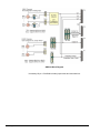
DBK214 Block Diagram
* Accessory Kit p/n 1139-0800 includes jumper wires and a screw driver.
DBK214, pg. 2
967894
DBK Option Cards and Modules
Connection Tips
CAUTION
Turn off power to the host PC and externally connected equipment prior to connecting
cables or signal lines to DBKs. Electric shock or damage to equipment can result even
under low-voltage conditions.
Take ESD precautions (packaging, proper handling, grounded wrist strap, etc.)
Use care to avoid touching board surfaces and onboard components. Only handle
boards by their edges (or ORBs, if applicable). Ensure boards do not come into
contact with foreign elements such as oils, water, and industrial particulate.
Do not confuse connectors. Ensure that you only connect P1 I/Os to P1, P2 I/Os to P2,
and P3 I/Os to P3. Improper connection may result in equipment damage.
When using P4, e.g., for a DaqBoard/2000, be sure to align the P4 orientation
indicators [white arrows] prior to mating the P4 connectors.
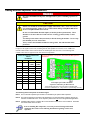
1.
Ensure power is removed from all device(s) to be connected.
2.
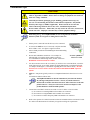
As soon as the DBK214 cover is removed, verify that the Host
Power LED is “Off.” See figure at right for location.
3.
Observe ESD precautions when handling the board and making
connections.
4.
Do not make redundant connections. For example, for
ANALOG IN you could use the P1 (DB37) connector,
or Terminal Blocks TB9 through TB12, or BNC connectors.
Redundant connections must be avoided.
5.
You do not need to remove the cover unless you need to access a terminal block, customize
an RC filter network, or set a BNC channel to Single-Ended mode or to Differential mode
(via Jumpers J0 through J7). Information regarding these tasks follows shortly. RC filter
networks are not to be made or used in association with additional DBK expansion
options.
6.
DBK214’s 100-pin P4 typically connects to a DaqBoard/2000 Series board’s P4 via a CA195
one-hundred conductor ribbon cable.
The DaqBoard/2000 Series boards communicate [external from the host
PC] through a 100-pin P4 connector. The P1, P2, and P3 connectors
discussed in association with these boards are subset connectors of the 100pin P4 connector. The System Connections and Pinouts chapters of the
product hardware manuals include pinouts.
7.
Connections to the DB37 connectors are made via CA-37 cables or CA-255 cables:
(a) P1 connects to an analog DBK card or module’s P1 connector.
(b) P2 connects to a Digital DBK card or module’s P2 connector.
(c) P3 connects to a Pulse/Frequency DBK card module’s P3 connector.
8.
Refer to the separate CE Cable Kit instructions that are included with the associated CE cable
kit. Refer to the Declaration of Conformity in regard to meeting CE requirements.
DBK Option Cards and Modules
967894
Location of DBK214’s
Host Power LED
DBK214, pg. 3
System Examples
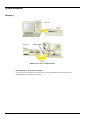
Example 1:
DBK214 Connected to a DaqBoard/2000
Note regarding the above system example:
A CA-195 100-conductor ribbon cable connects the P4 connector of the DBK214 to the P4 connector of the
DaqBoard/2000 (which is installed in the host PC).
DBK214, pg. 4
967894
DBK Option Cards and Modules
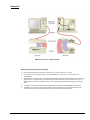
Example 2:
DBK214 Connected to a DaqBook/2001
Notes regarding the above system example:
1)
Either of two Ethernet cables can be used: CA-242 is a 1.5 ft cable; CA-242-7 is a 7 ft. cable.
2)
A CA-255 [or CA-37] cable is being used to connect the DBK214’s P1 connector to the P1 connector of the
DaqBook/2001.
3)
The DBK214’s P1 connector [rear panel, lower-left] connects to the internal screw-terminal board to which analog I/O
signals could be connected via wire. The wires would be routed out through the upper slots of the front panel. In
addition, BNC connectors (for channels 0 through 7) connect [through the printed circuit board] to the P1 terminal
blocks.
4)
A CA-255 [or CA-37] cable is used to connect the DBK214’s P2 connector to the DaqBook/2001 P2 connector.
5)
The DBK214’s P2 connector connects to the internal screw-terminal board, to which digital I/O signals could be
connected via wire. The wires would be routed out through the upper slots of the front panel.
DBK Option Cards and Modules
967894
DBK214, pg. 5
Using the Screw-Terminal Blocks
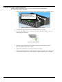
You must remove the DBK214 module’s cover plate to access the screw terminal blocks.
This is described in steps 1 and 2 below.
1.
Remove the top inward screws from each of the 4 mounting brackets. See following figure.
To remove the cover plate you
must first remove the top
inward screw from each of the
4 mounting brackets.
The Cover Plate is Secured by 4 Srews [2 Screws per-side]
2.
After the 4 screws have been removed, carefully remove the cover plate.
3.
As soon as the DBK214 cover is removed, verify that the Host Power LED is “Off.” See
following figure for location.
Host Power LED Location
DBK214, pg. 6
4.
Make the wiring connections to the terminals. Refer to the board’s silkscreen and to
the pin correlations on the next few pages.
5.
Tighten the terminal block screws snug; but do not over-tighten.
6.
After all terminal connections are made and verified correct, return the cover to the unit and
secure in place with the 4 screws removed earlier. Tighten snug, but do not over-tighten.
967894
DBK Option Cards and Modules
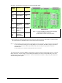
In general, the following terminal block-to-signal relationships apply:
DBK214
Terminal
Blocks
Used for . . .
Alternative
TB9
TB10
ANALOG INPUT
P1, P4*
BNC 0 thru 7
TB11
TB12
ANALOG INPUT
P1, P4*
TB5
TB6
TB7
TB8
DIGITAL I/O
P2 or P4*
TB13**
TB14**
ANALOG INPUT
BNC Channels
0 thru 7**
TB15
TB16
(Note 1)
USER
CONFIGURABLEB
NC Channels
A thru H
(See Note 1)
PULSE/
FREQUENCY/
DIGITAL I/O
ANALOG OUTPUT
P3 or P4*
TB1
TB2
TB3
TB4
P1, P4*
TB9,TB10
DBK214 Board
Notes: (1) The P2 and P3 DB37 Connectors and their associated
“device-internal” cables are not shown.
(2) DBK214 does not make use of P5 [top center].
*
P4 is used for connecting to DaqBoard/2000 Series devices.
**
TB13 and TB14 are “virtual” terminal blocks which are routed in the printed circuit board to TB9 and TB10. The TB13 and TB14
silk-screened locations on the DBK214 board do not have physical screw terminal blocks.
Note 1:
TB15 and TB16 are used for optional user-configured BNC connectors A through H. These connectors can be configured
on a per-channel basis as Analog [Input or Output], Digital I/O, or Counter/Timer. When BNC A through H are used, the
user must route wires from the “BNC routing terminal blocks” (TB15 and TB16) to the appropriate functional TB
termination points.
Accessory Wire Kit, p/n 1139-0800 includes jumper wires and a screwdriver.
The following pages correlate the DBK214 terminal block connectors with the associated pins of the P1, P2, and P3
DB37 connectors. Note that chapter 2 of the DBK Options Manual (457-0905) contains additional pin-outs, and
includes references to the 100-pin P4 connector. Also note that hardware manuals for the primary data acquisition
devices include pinout chapters.
DBK Option Cards and Modules
967894
DBK214, pg. 7
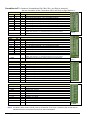
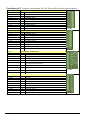
Correlation to P1 – Pertains to Terminal Blocks TB9, TB10, TB11, and TB12 for Analog I/O.
Also see “Correlation to BNC Terminations (TB13 and TB14) on page DBK214-11.”
TB9
DIFF
SE
0H
0
0L
8
1H
1
1L
9
2H
2
2L
10
3H
3
3L
11
FILT CAP LO
SGND
TB10
DIFF
SE
4H
4
4L
12
5H
5
5L
13
6H
6
6L
14
7H
7
7L
15
FILT CAP LO
SGND
P1 Pin Number and Description
37
18
36
17
35
16
34
15
N/A
19
CH 0 IN (Single-Ended Mode) / CH 0 HI IN (Differential Mode)
CH 8 IN (Single-Ended Mode) / CH 0 LO IN (Differential Mode)
CH 1 IN (Single-Ended Mode) / CH 1 HI IN (Differential Mode)
CH 9 IN (Single-Ended Mode) / CH 1 LO IN (Differential Mode)
CH 2 IN (Single-Ended Mode) / CH 2 HI IN (Differential Mode)
CH 10 IN (Single-Ended Mode) / CH 2 LO IN (Differential Mode)
CH 3 IN (Single-Ended Mode) / CH 3 HI IN (Differential Mode)
CH 11 IN (Single-Ended Mode) / CH 3 LO IN (Differential Mode)
For RC filter networks install a wire jumper between the relevant FILT CAP LO and
AGND. Note that there is no association between FILT CAP LO and P4.
Signal Ground, Sense Common; reference ground, not for general use.
P1 – TB9
(Note 2)
P1 Pin Number and Description
33
14
32
13
31
12
30
11
N/A
19
CH 4 IN (Single-Ended Mode) / CH 4 HI IN (Differential Mode)
CH 12 IN (Single-Ended Mode) / CH 4 LO IN (Differential Mode)
CH 5 IN (Single-Ended Mode) / CH 5 HI IN (Differential Mode)
CH 13 IN (Single-Ended Mode) / CH 5 LO IN (Differential Mode)
CH 6 IN (Single-Ended Mode) / CH 6 HI IN (Differential Mode)
CH 14 IN (Single-Ended Mode) / CH 6 LO IN (Differential Mode)
CH 7 IN (Single-Ended Mode) / CH 7 HI IN (Differential Mode)
CH 15 IN (Single-Ended Mode) / CH 7 LO IN (Differential Mode)
For RC filter networks install a wire jumper between the relevant FILT CAP LO and
AGND. Note that there is no association between FILT CAP LO and P4.
Signal Ground, Sense Common; reference ground, not for general use.
TB11
TTL TRIG
A/I CLK
EXP 5
EXP 6
EXP 7
EXP 8
EXP 9
EXP 10
EXP 11
AGND
P1 Pin Number and Description
25
TTL Trigger, Digital IN, External TTL Trigger Input
20
A/I Clock, External ADC Pacer Clock Input/ Internal ADC Pacer Clock Output
5
Expansion 5. Digital OUT, external GAIN select bit 1
6
Expansion 6. Digital OUT, external GAIN select bit 0
3
Expansion 7. Digital OUT, external ADDRESS, select bit 3
22
Expansion 8. Digital OUT, external ADDRESS, select bit 2
4
Expansion 9. Digital OUT, external ADDRESS, select bit 1
23
Expansion 10. Digital OUT, external ADDRESS, select bit 0
26
Expansion 11. Simultaneous Sample and Hold (SSH)
*
Analog Ground, Common
TB12
AGND
AGND
AGND
AGND
AGND
AGND
+ 15 V
- 15 V
AGND
+5V
P1 Pin Number and Description
*
Analog Ground, Common
*
Analog Ground, Common
*
Analog Ground, Common
*
Analog Ground, Common
*
Analog Ground, Common
*
Analog Ground, Common
21
Expansion, +15 V Power
2
Expansion, -15 V Power
*
Common Ground
1
Expansion, +5 V Power
P1 – TB10
(Note 2)
P1 – TB11
P1 – TB12
*Refer to Ground Correlation Tables in the DBK Options Manual (457-0905), chapter 2, System Connections and Pinouts.
Note 2: For TB9 and TB10, the filter network portion of the silkscreen is not shown. Instead, the DIFF and SE channel
identifiers have been moved next to the screws for ease in identification.
DBK214, pg. 8
967894
DBK Option Cards and Modules
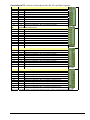
Correlation to P2 – Pertains to Terminal Blocks TB5, TB6, TB7, and TB8 for Digital I/O.
TB5
DGND
DGND
A7
A6
A5
A4
A3
A2
A1
A0
P2 Pin Number and Description
*
Digital Ground, Common
*
Digital Ground, Common
30
Digital I/O: P2, Digital Port A, Bit 7; or P2 Expansion Data Bit 15
31
Digital I/O: P2, Digital Port A, Bit 6; or P2 Expansion Data Bit 14
32
Digital I/O: P2, Digital Port A, Bit 5; or P2 Expansion Data Bit 13
33
Digital I/O: P2, Digital Port A, Bit 4; or P2 Expansion Data Bit 12
34
Digital I/O: P2, Digital Port A, Bit 3; or P2 Expansion Data Bit 11
35
Digital I/O: P2, Digital Port A, Bit 2; or P2 Expansion Data Bit 10
36
Digital I/O: P2, Digital Port A, Bit 1; or P2 Expansion Data Bit 9
37
Digital I/O: P2, Digital Port A, Bit 0; or P2 Expansion Data Bit 8
TB6
+5 V
+5 V
DGND
DGND
DGND
DGND
DGND
DGND
DGND
DGND
P2 Pin Number and Description
18
Expansion +5 V Power
20
Expansion +5 V Power
*
Digital Ground, Common
*
Digital Ground, Common
*
Digital Ground, Common
*
Digital Ground, Common
*
Digital Ground, Common
*
Digital Ground, Common
*
Digital Ground, Common
*
Digital Ground, Common
TB7
DGND
DGND
C7
C6
C5
C4
C3
C2
C1
C0
P2 Pin Number and Description
*
Digital Ground, Common
*
Digital Ground, Common
22
Digital I/O: P2, Digital Port C, Bit 7; or P2 Expansion Data Bit 7
23
Digital I/O: P2, Digital Port C, Bit 6; or P2 Expansion Data Bit 6
24
Digital I/O: P2, Digital Port C, Bit 5; or P2 Expansion Data Bit 5
25
Digital I/O: P2, Digital Port C, Bit 4; or P2 Expansion Data Bit 4
26
Digital I/O: P2, Digital Port C, Bit 3; or P2 Expansion Data Bit 3
27
Digital I/O: P2, Digital Port C, Bit 2; or P2 Expansion Data Bit 2
28
Digital I/O: P2, Digital Port C, Bit 1; or P2 Expansion Data Bit 1
29
Digital I/O: P2, Digital Port C, Bit 0; or P2 Expansion Data Bit 0
TB8
DGND
DGND
B0
B1
B2
B3
B4
B5
B6
B7
P2 Pin Number and Description
*
Digital Ground, Common
*
Digital Ground, Common
10
Digital I/O: P2, Digital Port B, Bit 0; or P2 Expansion READ Output
9
Digital I/O: P2, Digital Port B, Bit 1; or P2 Expansion WRITE Output
8
Digital I/O: P2, Digital Port B, Bit 2; or P2 Expansion RESET Output
7
Digital I/O: P2, Digital Port B, Bit 3; or P2 Expansion Address Bit 4 Out
6
Digital I/O: P2, Digital Port B, Bit 4; or P2 Expansion Address Bit 3 Out
5
Digital I/O: P2, Digital Port B, Bit 5; or P2 Expansion Address Bit 2 Out
4
Digital I/O: P2, Digital Port B, Bit 6; or P2 Expansion Address Bit 1 Out
3
Digital I/O: P2, Digital Port B, Bit 7; or P2 Expansion Address Bit 0 Out
P2 – TB5
P2 – TB6
P2 – TB7
P2 – TB8
*Refer to Ground Correlation Tables in the DBK Options Manual (457-0905), chapter 2, System Connections and Pinouts.
DBK Option Cards and Modules
967894
DBK214, pg. 9
Correlation to P3 – Pertains to Terminal Blocks TB1, TB2, TB3, and TB4 for Pulse/Frequency/Digital I/O.
TB1
D0
D1
D2
D3
D4
D5
D6
D7
DGND
+5V
P3 Pin Number and Description
10
P3 Digital Port Bit 0
9
P3 Digital Port Bit 1
8
P3 Digital Port Bit 2
7
P3 Digital Port Bit 3
6
P3 Digital Port Bit 4
5
P3 Digital Port Bit 5
4
P3 Digital Port Bit 6
3
P3 Digital Port Bit 7
*
Digital Ground, Common
20
Expansion, +5 Volt Power
TB2
D8
D9
D10
D11
D12
D13
D14
D15
DGND
DGND
P3 Pin Number and Description
29
P3 Digital Port Bit 8
28
P3 Digital Port Bit 9
27
P3 Digital Port Bit 10
26
P3 Digital Port Bit 11
25
P3 Digital Port Bit 12
24
P3 Digital Port Bit 13
23
P3 Digital Port Bit 14
22
P3 Digital Port Bit 15
*
Digital Ground, Common
*
Digital Ground, Common
TB3
P3 Pin Number and Description
P3 – TB1
P3 – TB2
CH0 (DAC0)
AGND
EXP 0 (DAC2)
AGND
34
*
32
*
Analog Out; Analog DAC 0 Output
Analog Ground, Common; intended for use with DACs
Analog Out; Analog DAC 2 Output
Analog Ground, Common; intended for use with DACs
CH1 (DAC1)
33
Analog Out; Analog DAC 1 Output
A/O CLK
21
Analog Out Clock; External DAC Pacer Clock Input/
Internal DAC Pacer Clock Output
EXP 1 (DAC3)
31
Analog Out; Analog DAC 3 Output
DGND
*
Digital Ground, Common
+15 V
19
Expansion, + 15 VDC
37
Expansion, -15 VDC
P3 – TB3
-15 V
TB4
P3 Pin Number and Description
EXP 2
12
Reserved
EXP 3
13
Reserved
EXP 4
14
Reserved
TMR 0
15
P3 Timer 0 Output
TMR 1
16
P3, Timer 1 Output
CNT 3
35
P3 Counter 3 Input
CNT 2
17
P3 Counter 2 Input
CNT 1
36
P3 Counter 1 Input
CNT0
18
P3 Counter 0 Input
DGND
*
Digital Ground, Common
P3 – TB4
*Refer to Ground Correlation Tables in the DBK Options Manual (457-0905), chapter 2, System Connections and Pinouts.
DBK214, pg. 10
967894
DBK Option Cards and Modules
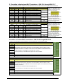
P1 Correlation to Analog Input BNC Terminations – BNC Ch 0 through BNC Ch 7
“Virtual” Terminal Blocks TB13 and TB14 for ANALOG INPUT connect to TB9 and TB10 through the printed circuit board.
TB13 (“Virtual” Terminal Block)
BNC CH
DIFF
SE
BNC0+
0H
0
BNC00L
8
BNC1+
1H
1
BNC11L
9
BNC2+
2H
2
BNC22L
10
BNC3+
3H
3
BNC0+
3L
11
AGND
AGND
N/A
N/A
N/A
N/A
TB14 (“Virtual” Terminal Block)
BNC CH
DIFF
SE
BNC4+
4H
4
BNC44L
12
BNC5+
5H
5
BNC55L
13
BNC6+
6H
6
BNC66L
14
BNC7+
7H
7
BNC7+
7L
15
AGND
AGND
N/A
N/A
N/A
N/A
P1 Pin Number and Description
Pin
SE = Single Ended ; DIFF = Differential
37
CH 0 IN (SE) / CH 0 HI IN (DIFF)
18
CH 8 IN (SE) / CH 0 LO IN (DIFF)
36
CH 1 IN (SE) / CH 1 HI IN (DIFF)
17
CH 9 IN (SE) / CH 1 LO IN (DIFF)
35
CH 2 IN (SE) / CH 2 HI IN (DIFF)
16
CH 10 IN (SE) / CH 2 LO IN (DIFF)
34
CH 3 IN (SE) / CH 3 HI IN (DIFF)
15
CH 11 IN (SE) / CH 3 LO IN (D DIFF)
*
*
J0
TB13 does not physically exist on
DBK214. A silkscreen of TB13 is
present as a visual aid to signal
routing and configuration.
J1
J2
J3
Analog Ground
Analog Ground
P1 Pin Number and Description
Pin
SE = Single Ended ; DIFF = Differential
33
CH 4 IN (SE) / CH 4 HI IN (DIFF)
14
CH 12 IN (SE) / CH 4 LO IN (DIFF)
32
CH 5 IN (SE) / CH 5 HI IN (DIFF)
13
CH 13 IN (SE) / CH 5 LO IN (DIFF)
31
CH 6 IN (SE) / CH 6 HI IN (DIFF)
12
CH 14 IN (SE) / CH 6 LO IN (DIFF)
30
CH 7 IN (SE) / CH 7 HI IN (DIFF)
11
CH 15 IN (SE) / CH 7 LO IN (DIFF)
*
*
Jumper Used
N/A
N/A
Jumper Used
Analog Ground
Analog Ground
J4
A header located beneath TB14 and
TB16 is used to set the BNC
channels to Single-Ended or to
Differential. Simply place channel’s
2-pin jumper in the appropriate
position (SE or DIFF).
TB14 does not physically exist on
DBK214. A silkscreen of TB14 is
present as a visual aid to signal
routing and configuration.
J5
J6
J7
N/A
N/A
A header located beneath TB14 and
TB16 is used to set the BNC
channels to Single-Ended or to
Differential. Simply place channel’s
2-pin jumper in the appropriate
position (SE or DIFF).
Correlation to Custom BNC Terminations – BNC Ch A through BNC Ch H
Pertains to Terminal Blocks TB15 and TB16 for Custom Configuration on a per-channel basis.
TB15 (“Routing” Terminal Block)
BNC CH
Description
BNCA+
BNCABNCB+
BNCBBNCC+
BNCCBNCD+
BNCD+
AGND
AGND
BNC channels A through D are configured on a per-channel basis by the user. TB15 is a routing
terminal block used to connect BNCs (A thru D) to the desired signals, which are selected via a second
DBK214 terminal block. For example: a user could run a wire from BNCA+ to TB4 screw terminal
“TMR0” and BNCA- to TB4 DGND to create a BNC timer connection.
Accessory Wire Kit, p/n 1139-0800 includes jumper wires and a screwdriver.
Analog Ground *
Analog Ground *
TB15
TB16 (“Routing” Terminal Block)
BNC CH
Description
BNCA+
BNCABNCB+
BNCBBNCC+
BNCCBNCD+
BNCD+
AGND
AGND
BNC channels E through H are configured on a per-channel basis by the user. TB16 is a routing
terminal block used to connect BNCs (E thru H) to the desired signals, which are selected via a second
DBK214 terminal block.
Customizing is as described for BNCA through BNCD above.
Accessory Wire Kit, p/n 1139-0800 includes jumper wires and a screwdriver.
Analog Ground *
Analog Ground *
TB16
DBK Option Cards and Modules
967894
DBK214, pg. 11
Adding Resistor/Capacitor Filter Networks
WARNING
Disconnect the DBK214 from power and signal sources prior to installing capacitors or
resistors.
CAUTION
Ensure wire strands do not short power supply connections (+15 V, -15 V, +5 V, etc.) to
any terminal potential. Failure to do so could result in damage to DaqBook/2000 Series
devices or DaqBoard/2000 Series boards.
Do not exceed maximum allowable inputs (as listed in product specifications). There
should never be more than 30 V with reference to analog ground (AGND) or earth
ground.
You must provide strain-relief (lead slack) to all leads leaving the module. Use tie-wraps
[not included] to secure strain-relief.
Always connect the CHASSIS terminal to earth ground. This will maximize static
protection.
If a channel is not associated with a DBK expansion option you can install a customized RC filter network
to improve the signal-to noise ratio, assuming that an unacceptable level of noise exists. DBK214’s
internal board includes silk-screened sockets for installing RC filter networks. The following table
contains values that are typical for RC filter network components.
Typical One-Pole Low Pass Filter
Values
for DBK214
R
Ohms
C
µF
510
510
510
510
510
510
510
510
470
1
0.47
0.22
0.1
0.047
0.022
0.01
0.0047
0.0033
f
Hertz
(-3dB)
312
664
1419
3122
6643
14192
31223
66431
102666
Do not use RC filters in conjunction with additional DBK expansion
accessories.
f
kHz
(-3dB)
0.31
0.66
1.42
3.12
6.64
14.19
31.22
66.43
102.67
An Example of Customer-Installed
Capacitors and Filters for RC Networks
In this example Channels 0 and 8 are shown as Single-Ended.
Channel 1 is Differential, i.e., using 1H and 1L (channel High and Low).
The following three notes pertain to the above figure.
Note 1: The 3 horizontal capacitors [as oriented in the illustration] are optional filter capacitors.
Note 2: The vertical capacitor [as oriented in the illustration] is an optional isolation capacitor used for the
reduction of Differential noise. Such capacitor placement is not used in Single-Ended applications.
Note 3: If installing filter resistors, carefully drill out the indicated centers with a 1/16 inch drill-bit. Otherwise
the resistor will be short-circuited.
Prior to installing RC components, review the previous Warning and Caution
statements, then read over the following information regarding resistors and
capacitors.
DBK214, pg. 12
967894
DBK Option Cards and Modules
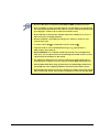
• Do not use RC filters in conjunction with additional DBK expansion accessories.
• Prior to installing a resistor to the filter network you must drill a 1/16” hole through
the center pinhole [beneath the board’s silkscreen resistor symbol] as indicated in the
preceding figure. Failure to do so will short-circuit the resistor.
• Do not drill holes on the board for channels, unless those channels are to receive a
filter network (see preceding statement).
• Resistors should be ¼ watt, film-type with up to 5% tolerance. Do not use wirewound resistor types.
• A resistor value of 510 Ω is recommended. Do not exceed 510 Ω.
• Capacitors used are to be of the film dielectric type (e.g., polycarbonate or
NPO ceramic), above 0.001 µF.
• RECOMMENDED: For reduction of both Common Mode Noise and Differential
Mode Noise, use one capacitor between Channel High and AGND; and use a second
capacitor between Channel Low and AGND.
• For reduction of Differential Noise [when no reduction of Common Mode Noise is
needed] position a capacitor across the respective Channel High and Channel Low.
• When in Differential Mode, using capacitors between Channel High, Channel Low,
and AGND may cause a slight degradation of wideband Common Mode rejection.
• When making a RC filter network, always install a wire jumper between the relevant
FILT CAP LO and AGND. FILT CAP LO terminals are located on TB9 and TB10.
DBK Option Cards and Modules
967894
DBK214, pg. 13
Specifications for DBK214
Operating Environment:
Temperature: -30°C to 70°C
Relative Humidity: 95% RH, non-condensing
Connectors:
P1: male DB37 connector for analog expansion or connection to primary acquisition device*
P2: male DB37 connector for digital expansion or connection to primary acquisition device*
P3: male DB37 connector for pulse/frequency/digital I/O, analog output, or connection to primary
acquisition device*
P4: 100-pin connector for connection to a /2000 Series device that includes a P4 connector;
e.g., DaqBoard/2000.
Screw Terminals: 14 banks of 10-connector blocks
Wire Size: 12 to 28 AWG
Dimensions:
285 mm W x 220 mm D x 45 mm H (11” x 8.5” x 2.7”)
Weight:
1.36 kg (3 lbs)
Cables and Accessories:
Item Description
Part Number
Rack Mount Kit, p/n
RackDBK4
100-conductor expansion cables; mate with P4 connectors:
3 ft., non-CE Compliant
CA-195
3 ft., CE Compliant
CA-209
6 ft., non-CE Compliant
CA-195-6
37-conductor cables; mate with DB37 connectors:
2 in., shielded T-cable
CA-255-2T
4 in., shielded T cable
CA-255-4T
8 in., shielded T cable
CA-255-8T
37-conductor ribbon cable
CA-37-X
Accessory Wire Kit
Includes jumper wires and a
screwdriver.
1139-0800
*DaqBook/2000 Series, DaqLab/2000 Series, DaqScan/2000 Series
Specifications subject to change without notice.
DBK214, pg. 14
967894
DBK Option Cards and Modules
Reference Notes:
In regard to calculating system power requirements refer to the DBK Basics section.
Chapter 2 of the DBK Options Manual includes pinouts for P1, P2, P3, and P4. Refer
to pinouts applicable to your system, as needed.
For a quick comparison of all DBK200 Series boards, refer to the DBK200 Series
Matrix. The matrix is located just before the DBK200 section of this manual.
Refer to the user manual for the primary data acquisition device as needed. The user’s
manuals include device specific pinouts.
DBK Option Cards and Modules
967894
DBK214, pg. 15
DBK214, pg. 16
967894
DBK Option Cards and Modules