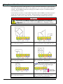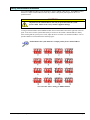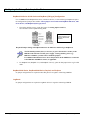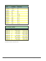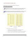
1
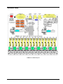
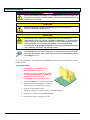
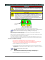
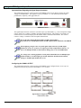
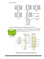
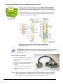
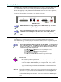
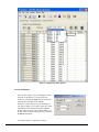
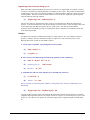
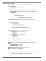
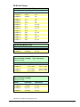
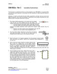
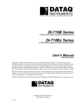
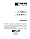
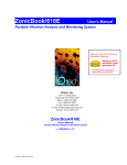
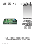
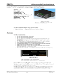
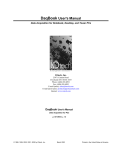
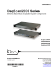
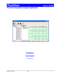
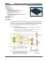
DBK48
Multipurpose Isolated Signal-Conditioning Module
Supports up to Sixteen 8B Modules
Description …… 1
Safety Concerns …… 2
Hardware Setup …… 2
Installing 8B Modules …… 4
Installing Plug-in Resistors to Create 4 to 20 mA Loops …… 5
Making Terminal Block Connections …… 6
Setting DBK48 Module Addresses …… 7
Configuring the Primary Data Acquisition Device …… 8
CE Compliance …… 9
Connecting the DBK48 to the Primary Data Acquisition Device …… 9
Using the DB25 Signal Output Connector …… 10
Powering the System …… 13
Software Setup …… 13
Specifications …… 16
Description
The DBK48 module can accommodate up to sixteen 8B isolated-input signal-conditioning modules for use
with Daq systems. A single cable connects the DBK48 output to the P1 analog input connector on the
primary device. One Daq system can support up to 16 DBK48 modules, providing a total of 256 isolated
analog input channels. The A/D converter scans the DBK48 channels at the same 5 µs/channel rate that it
scans all other channels from DBK series analog expansion and signal conditioning cards.
Other features of DBK48 include:
• Built-in power supply that operates from 10 to 30 VDC and can power a full complement of
8B modules (even with bridge excitation).
• Removable, plug-in screw-terminal blocks for convenient connection of 8B modules.
• On-board cold-junction sensing for thermocouple 8B modules.
• For each 8B module, 250 V isolation from the system and from other channels.
Note 1: Only channels 0, 2, 4, 6, 8, 10, 12, and 14 can be connected
to excitation. For example, in the above block diagram
Channel 0 could be connected to Excitation; Channel 1
could not.
Note 2: Each channel can accept a plug-in resistor to serve as a
current shunt. In the above diagram, Channel 0 has a
current shunt installed, Channel 1 does not. Only currentinput type modules require the plug-in resistors. The plug-in
resistors must be removed for all other module types.
8B Isolated Signal Conditioning Module
967792
DKB48, pg. 1
Safety Concerns
WARNING
Shock Hazard! Voltages above 50 Vrms AC and voltages above 100 VDC are
considered hazardous. Safety precautions are required when 8B modules are used in
situations that require high-voltage isolation from the rest of the system. Failure to
practice electrical safety precautions could lead to injury or death.
DBK48 has a 250 VDC isolation specification. This is in a normal environment free of conductive
pollutants and condensation. The 250 VDC rating requires a proper earth ground connection to the chassis
and treatment of adjacent inputs as potentially hazardous.
Input cables must be rated for the isolation potential in use. Line voltage ratings are much lower than the
DC isolation values specified due to transients that occur on power lines. Never remove the cover unless all
inputs with potentially hazardous voltages are removed. The cover must be securely screwed on during
use.
Some things to remember:
• Properly tighten all chassis screws before system use.
• Never plug in or unplug potentially hazardous connections with power applied to any
connected equipment.
• Never attempt to change 8B modules or remove the cover plate while power is applied to
the DBK48. You could short out internally exposed circuits and cause personal injury or
equipment damage.
• Disconnect power, all equipment, and signal lines from the DBK48 prior to installing
8B modules.
Reference Note:
Refer to user manual that is associated with your primary Daq device.
DBK48, pg. 2
967792
8B Isolated Signal Conditioning Module
Hardware Setup
DBK48 Circuit Board Layout
8B Isolated Signal Conditioning Module
967792
DKB48, pg. 3
Installing 8B Modules
WARNING
Electric shock hazard! Turn off power to the DBK48 and all connected modules and
devices before inserting or removing modules. Failure to do so could lead to injury or
death due to electric shock.
CAUTION
Handle the 8B module carefully while inserting pins into the circuit board.
Do not over-tighten the mounting screw.
CAUTION
The discharge of static electricity can damage some electronic components.
Semiconductor devices are especially susceptible to ESD damage. You should always
handle components carefully, and you should never touch connector pins or circuit
components unless you are following ESD guidelines in an appropriate ESD
controlled area. Such guidelines include the use of properly grounded mats and wrist
straps, ESD bags and cartons, and related procedures.
If the DBK48 is not connected to a Daq device via the P1 connector, then remove the
Rnets from S01 and S02. These resistor networks connect each 8B module’s output to
the multiplexer for P1.
Up to sixteen 8B modules can be installed onto the DBK48 circuit board. The preceding figure indicates
module locations.
To install 8B modules:
DBK48, pg. 4
1.
Turn off power to the DBK48 and all
connected modules and devices.
2.
Disconnect power, all equipment, and signal
lines from the DBK48 prior to installing 8B
modules. Be aware that isolated
measurements can present lethal voltages!
3.
Remove the DBK48 top cover plate and set aside.
4.
Align the 8B module’s retaining screw and pins
with the holes in the circuit board (see figure).
5.
Gently press the module into place.
6.
Tighten the retaining screw snug, but DO NOT OVERTIGHTEN.
7.
Repeat steps 3, 4, and 5 for each additional module.
8.
Return and secure the cover plate to the unit.
967792
8B Isolated Signal Conditioning Module
Installing Plug-in Resistors to Create 4 to 20 mA Loops with 8B Voltage-Input Modules
WARNING
Electric shock hazard! Turn off power to the DBK48 and all connected modules and
devices before inserting or removing resistors. Failure to do so could lead to injury or
death due to electric shock.
CAUTION
The discharge of static electricity can damage some electronic components.
Semiconductor devices are especially susceptible to ESD damage. You should always
handle components carefully, and you should never touch connector pins or circuit
components unless you are following ESD guidelines in an appropriate ESD
controlled area. Such guidelines include the use of properly grounded mats and wrist
straps, ESD bags and cartons, and related procedures.
Current Shunt
Resistors
Location of Shunt Resistor Plug-In
Shown with shunt resistors plugged-in for Channel 0 (at R0) and Channel 2 (at R2)
Only voltage-input type modules require the plug-in shunt resistors. The plug-in resistors
must be removed for all other module types, including current-input type.
Inputs to monitor the commonly used 4 to 20mA current loops most often employ a 250Ω precision
resistor to develop a 1 to 5 VDC voltage drop.
Ideally, a resistor for such purpose should have a 0.1% tolerance (or better) with a minimum power rating
of 0.25W and a temperature coefficient of at least 25ppm/°C.
Lower values of resistance, for example, 62.5Ω [for a lower voltage drop within the loop of 0.25 to 1.25
VDC] will require that the host data acquisition device use a gain of x4 to maximize the signal resolution.
To create a 4 to 20mA current loop:
1. Turn off power to the DBK48 and all connected modules and devices.
2. Disconnect power, all equipment, and signal lines from the DBK48 prior to installing the
resistors. Be aware that isolated measurements can present lethal voltages!
3. Remove the DBK48 top cover plate and set aside.
4. Carefully plug the shunt resistor into the applicable plug-in location for the designated channel;
for example, R0 for Channel 0, R1 for Channel 1, R2 for Channel 2, etc. Repeat for each channel
as applicable.
DO NOT solder the shunt resistors in place.
Only voltage-input type modules require these resistors. The plug-in resistors
must be removed for all other module types, including current-input type.
5. Reinstall the DBK48 top cover plate and secure in place.
8B Isolated Signal Conditioning Module
967792
DKB48, pg. 5
Making Terminal Block Connections
Input signals (and excitation when applicable) are wired to removable terminal blocks. Eight such blocks
can accept 2 channel inputs each. However, only channels 0, 2, 4, 6, 8, 10, 12, and 14 can be connected to
excitation. Thus the DBK48 is limited to 8 strain gages or 8 RTDs as only the even numbered channels
can be connected to excitation.
Each terminal block connects to a signal conditioning module within the DBK48. The blocks accept up to
14-gage wire into quick-connect screw terminals. Wiring schematics are provided below for RTDs,
thermocouples, 20 mA circuits, voltage (mV and V), and for full-bridge and half-bridge strain gages.
WARNING
Shock Hazard! The DBK48 is designed to sense signals that may carry dangerous
voltages. De-energize circuits connected to the DBK48 before changing the wiring or
configuration.
CH 0 is connected to a Full-Bridge Strain Gage.
CH 1 is shown not connected.
CH 0 is connected to a Half-Bridge Strain Gage.
CH 1 is connected for voltage input (mV or V).
CH 0 has a 3-wire connection to a potentiometer.
CH 1 is shown not connected.
CH 0 has a 3-wire connection to an RTD.
CH 1 is connected to a Thermocouple.
Only current-input type modules require the
plug-in resistors. The plug-in resistors must
be removed for all other module types.
CH 0 has a 2-wire connection to an RTD.
CH 1 is shown not connected.
DBK48, pg. 6
967792
CH 0 is shown not connected.
CH 1 is connected to a current shunt resistor
resulting in a 4 to 20 mA current loop.
8B Isolated Signal Conditioning Module
Setting DBK48 Module Addresses
Up to sixteen DBK48 modules can be attached to a single LogBook or Daq device. Each DBK48 module
must have a unique channel address because they connect to the primary data acquisition device via
parallel interface.
CAUTION
Adjustment of the channel address must only be performed when the system
power is OFF. Failure to do so may result in equipment damage.
To assign a channel address to the DBK48 module, first locate the DIP switch on the right side of the rear
panel. Four micro-switches [on the DIP switch] are used to set the module’s channel address in binary.
After ensuring that the system power is OFF, adjust the micro-switches to set the desired address. The 16
possible addresses are illustrated in the following figure.
Each module in the system must have a unique primary device channel address.
The 16 Possible Address Settings for DBK48 Modules
8B Isolated Signal Conditioning Module
967792
DKB48, pg. 7
Configuring the Primary Data Acquisition Device
DaqBook/100 Series & /200 Series and DaqBoard [ISA type] Configuration
Use of a DBK48 with a DaqBook/100 Series, /200 Series devices, or with an ISA-type DaqBoard requires
the configuration of jumpers JP1 and JP4. These jumpers are located on the DaqBook/100 Series, /200
Series devices, and DaqBoard [ISA type] board.
1.
If not using auxiliary power, set the JP1 jumper for Analog Option Card Use,
also referred to as the expanded analog mode.
Note:
These jumpers do not
apply to /2000 Series
Devices.
Required Jumper Settings in DaqBook/100 Series & /200 Series and ISA-Type DaqBoards
The JP1 default position (above) is necessary to power the interface circuitry of the
DBK48 via the internal ±15 VDC power supply. If using auxiliary power (e.g.,
DBK32A or DBK33) you must remove both JP1 jumpers.
For additional information refer to Power Requirements in the DBK Basics section and
to the DBK32A and DBK33 sections, as applicable.
2.
For DaqBook/100, DaqBook /112, and DaqBook /120 only, place the JP4 jumper in the single-ended
mode.
DaqBook/2000 Series, DaqBoard/2000 Series, DaqLab, and DaqScan
No jumper configurations are required on these Daq devices in regard to connecting a DBK48.
LogBooks
No jumper configurations are required on LogBook devices in regard to connecting a DBK48.
DBK48, pg. 8
967792
8B Isolated Signal Conditioning Module
CE Compliance
If your data acquisition system needs to comply with CE standards, the DBK48 must be connected to the
LogBook or Daq device by a CA-143-x cable. In addition, the CE compliant operating conditions must be
met as specified on the DBK48 module’s Declaration of Conformity card, which is shipped with the
module.
Reference Notes: If your data acquisition system needs to comply with CE standards,
refer to the following:
o the DBK48 Declaration of Conformity
o the CE Compliance section of Signal Management chapter of this manual
Connecting the DBK48 to the Primary Data Acquisition Device
Connect the DBK48 module as follows. Note that if your system needs to be CE Compliant, be sure to
read the preceding CE Compliance section prior to connecting the DBK48.
1.
For a single DBK48 module, connect one end of the P1 cable to the module’s male DB37 output
connector.
• For DaqBook applications - use a CA-37-x cable or a CA-255-xT cable.*
• For DaqBoard/2000 Series or /2000c Series boards - use a CA-37-x with a DBK200 Series
adapter.*
• For DaqBoard [ISA type] boards - use a CA-131-x cable.*
* CA-37-x and CA-131-x cables do not meet CE compliance requirements. Refer to the
preceding CE section if CE compliance must be met.
2.
Connect the free end of the cable to the P1 port of the LogBook or Daq device. For multiple DBK48
modules, use a CA-37-x (or CA-131-x) cable to daisy-chain several modules or an expansion
module. For example, three DBK48 modules could be connected to a LogBook or a Daq device via
a
CA-37-3 cable.
Note: For longer cable runs you can use a CA-113 cable to add 6 ft of length.
8B Isolated Signal Conditioning Module
967792
DKB48, pg. 9
Using the DB25 Signal Output Connector
Important Notes Regarding the Signal Output Connector
The signal output connector on the rear panel of the DBK48 can be used to directly measure the output
voltage of each 8B module. This applies to input-type modules, i.e., volts, millivolts, thermocouple,
potentiometer, frequency, strain gage, RTD, etc.
DBK48 Rear Panel
The signal output connector can also be used with output-type 8B modules, e.g., current output and voltage
output. In this case a voltage is applied to the signal output connector. This voltage is converted to an
isolated current or isolated voltage by the 8B module which is installed in that channel. The isolated
current or voltage is available on the front panel terminal block.
Be careful when mixing 8B input modules and 8B output modules.
If possible, do not mix 8B input modules and 8B output modules within the same DBK48.
When applying voltages to the rear panel signal output connector [for 8B outputmodules] it can be easy to short to an adjacent pin on the 25 pin DSUB connector. If
there is an 8B input-module on that channel, damage may occur to that 8B module.
If a voltage source is being applied to a front panel terminal block for an 8B input-type
module and there is an 8B output-type module mistakenly installed in that channel,
damage to the 8B output module may occur.
Configuring the SIGNAL OUTPUT
The signal output connector on the rear panel of the DBK48 can be configured in one of two ways via
jumper networks that are placed in sockets JMP1, 2, 3, 4, 5, and 6.
Signal Output Configuration Jumpers
as Oriented on PCB
DBK48, pg. 10
967792
8B Isolated Signal Conditioning Module
Jumper Assignments
JMP1
JMP2
JMP3
For JMP1 through JMP6:
CCHx = Single-ended I/O
channel of 8B
Module.
DSUBx = Pin x of the DB25
Signal Output
connector.
JMP4
JMP5 and JMP6
Bringing all Sixteen 8B Module Outputs to the DB25 Signal Output Connector
With three CA-19-8 jumper networks installed [one per socket] in JMP3, JMP4,
and JMP5 the signal output connector is pinned out as shown in the following
figure. This brings the outputs of all sixteen 8B modules to the 25-pin DSUB
Signal Output connector on the rear panel.
DB25 SIGNAL OUTPUT Pinout with JMP3, JMP4, JMP5 Installed
This configuration brings all 16 channel outputs to the DB25 Signal Output Connector.
8B Isolated Signal Conditioning Module
967792
DKB48, pg. 11
Bringing Eight 8B Module Outputs to the DB25 Signal Output Connector
With 3 jumper networks installed [one per socket] in JMP1, JMP2, and JMP6 the
signal output connector is pinned out as shown in the following figure. This only
brings the outputs of eight of the 8B modules, i.e., Ch 0, 2, 4, 6, 8, 10, 12, and 14.
When the Signal Output connector is pinned-out in this manner it can be used with a
CA-208-3 cable to bring the 8 channels out to the cable’s BNC connectors for easy
connection to other measuring equipment.
DB25 SIGNAL OUTPUT Pinout with JMP1, JMP2, JMP6 Installed
This configuration brings channel 0, 2, 4, 6, 8, 10, 12 and 14 outputs to the DB25
Signal Output Connector.
If the DBK48 is not connected to a Daq device via the P1 connector, then remove the Rnets
from S01 and S02. These resistor networks connect each 8B module’s output to the
multiplexer for P1.
Use the CA-208-3 cable as follows:
1.
Connect the DB25-end of the CA-208-3 cable
directly to DBK48’s 25-pin Signal Output
connector.
2.
Connect the CA-208-3 analog common banana
plug to the local ground of the measuring
equipment.
3.
Connect the CA-208-3 BNC connectors (for
channels 1 through 8) to the measuring
equipment.
Note 1: CA-208-3 connects directly to the signal output connector. However, another cable, which looks virtually the
same, is the CA-208 (with no”-3” extension). If you are using a CA-208 you must first connect a CA-35-18
cable to the DB25 connector on the DBK48; then connect the CA-208 to the CA-35-18 cable. For CA-208
users, a wiring diagram is provided immediately following the DBK48 specifications section.
DBK48, pg. 12
967792
8B Isolated Signal Conditioning Module
Powering the System
The DBK48 contains an internal power supply. The unit can be powered by an AC power adapter or any
10 to 30 VDC source, such as a 12 V car battery. For portable or field applications, DBK48 and the
primary Daq device can be powered by a DBK30A rechargeable battery module or DBK34 vehicle UPS
module. The supply input is fully isolated from the measurement system. If the fuse requires replacement,
use a
2 Amp Mini ATO Fuse, factory part number FU-8-2 (Littelfuse # 297-002).
DBK48 Rear Panel
DBK48’s internal power supply supplies power to the 8B modules only. The DIN5
Power Out connector is a pass-through to allow for a power daisy-chain.
Prior to daisy-chaining from one module’s power connector to another, be sure to
compute the power consumption for the entire system. Some modules may need
independent power adapters. See chapter 2 for information regarding power supply
issues.
Software Setup
You will need to set several parameters so DaqView can best meet your application requirements.
After the 8B module type is identified, DaqView figures out the m and b (of the mx+b equation) for proper
engineering units scaling. An example of the mx + b equation follows shortly.
LogView does not include the means to directly select the DBK48. To use a DBK48 and
its 8B modules with LogBook: Select DBK42 in LogView. This will recognize the DBK48, but
will identify it as a DBK42. For each 8B module, select the 5B module that exhibits the same
measurement ranges; three examples follow:
For SC-8B30-01 select SC-5B30-01 as both have an Input Range of ±10 mV;
and an Output Range of ±5V.
For SC-8B34-02 select SC-5B34-02 as both are Type 100 Ohm Pt;
with an Input Range of 0°C to +100°C.
For SC-8B47-T-07 select SC-5B47-T-07 as both are a Type T Thermocouple,
with an Input Range of 0°C to +200°C.
Reference Note:
o
For DaqView information refer to chapter 3, DBK Setup in DaqView and to the DaqView
PDF included on your data acquisition CD.
o
For LogView information refer to chapter 4, DBK Setup in LogView and to the LogView
section of the LogBook PDF included on your data acquisition CD. Also, see above
note.
o
The API includes functions applicable to the DBK48. Refer to related material in the
Programmer’s Manual (p/n 1008-0901) as needed.
PDF Note:
During software installation, Adobe® PDF versions of user manuals automatically install onto
your hard drive as a part of product support. The default location is in the Programs group,
which can be accessed from the Windows Desktop. Refer to the PDF documentation for
details regarding both hardware and software. Note that you can also access PDF documents
directly from the data acquisition CD via the <View PDFs> button on the CD’s opening
screen.
8B Isolated Signal Conditioning Module
967792
DKB48, pg. 13
DaqView Configuration Main Window
mX +b, an Example
The Customize Engineering Units dialog box can be
accessed via the DaqView Configuration main
window by activating the Units cell [for the desired
channel], then clicking to select mX+b.
From the Customize Engineering Units dialog box
(see figure at right), you can enter values for m and b
components of the equation that will be applied to
the data. There is also an entry field that allows you
to enter a label for the new units that may result from
the mX+b calculation.
An example of mX + b equation use follows.
DBK48, pg. 14
967792
8B Isolated Signal Conditioning Module
Engineering Units Conversion Using mx + b
Most of our data acquisition products allow the user to convert a raw signal input (for example, one that is
in volts) to a value that is in engineering units (for example, pressure in psi). The products accomplish this
by allowing the user to enter scale and offset numbers for each input channel, using the software associated
with the product. Then the software uses these numbers to convert the raw signals into engineering units
using the following “mx + b” equation:
(1)
Engineering Units = m(Raw Signal) + b
The user must, however, determine the proper values of scale (m) and offset (b) for the application in
question. To do the calculation, the user needs to identify two known values: (1) the raw signal values, and
(2) the engineering units that correspond to the raw signal values. After this, the scale and offset
parameters can be calculated by solving two equations for the two unknowns. This method is made clear
by the following example.
Example
An engineer has a pressure transducer that produces a voltage output of 10.5 volts when the measured
pressure is 3200 psi. The same transducer produces an output of 0.5 volt when the pressure is 0 psi.
Knowing these facts, m and b are calculated as follows.
A - Write a pair of equations, representing the two known points:
(2)
3200 = m(10.5) + b
(3)
0 = m(0.5) + b
B - Solve for m by first subtracting each element in equation (3) from equation (2):
(4)
3200 - 0 = m(10.5 – 0.5) + (b - b)
(5)
Simplifying gives you:
(6)
This means:
3200 = m(10)
m = 320
C - Substitute the value for m into equation (3) to determine the value for b:
(7)
0 = 320 (0.5) + b
(8)
Therefore:
b = - 160
Now it is possible to rewrite the general equation (1) using the specific values for m and b that we just
determined:
(9)
Engineering Units = 320(Raw Signal) - 160
The user can then enter the values of m and b into the appropriate location using the facilities provided by
compatible data acquisition software, for example: WaveView, DaqView, Personal DaqView, LogView, and
TempView. The software uses equation (9) to calculate signal values in engineering units from that point
on.
8B Isolated Signal Conditioning Module
967792
DKB48, pg. 15
Specifications – DBK48
Name/Function: DBK48, 16-slot Multi-Purpose Isolated Signal Conditioning Module
Operating Environment:
Temperature: -30°C to 70°C
Relative Humidity: 95% RH, non-condensing
Connectors:
System Connector: DB37 male, mates with P1 connector on primary acquisition device (Note 1)
Signal Connector: DB25, 5V output signals from the 8B modules
Power Connectors: Two DIN5 connectors; “Power In” and “Power Out” for daisy-chaining
Input Connections:
8 sets of removable screw terminal blocks, each with 6 connection points as follows:
st
1 channel voltage in (+V in, -V in)
1st channel excitation (+E, -E) (Note 2)
2nd channel voltage in (+V in, -V in)
Shunt-Resistor Socket: R0 through R15, plug-in resistor sockets.
One socket per channel for current loop inputs.
Cold-Junction Sensor: Enabled or disabled per channel via jumpers JP0 through JP15.
8B Module Capacity:
o Up to 16 voltage input
o Up to 16 thermocouple
o Up to 8 modules which require excitation; i.e.
strain gauge, potentiometer, RTD
See latest catalog or contact your sales representative in regard to
the types of 8B Modules available for your application.
Power Requirements: 10 to 30 VDC; or 120 VAC with AC-to-DC adapter
With 16 thermocouple-type modules (0.03 amps each):
10 VDC @ 0.30 A
15 VDC @ 0.20 A
25 VDC @ 0.12 A
With 8 strain-gage-type modules (0.2 amps each):
10 VDC @ 1.000 A
15 VDC @ 0.667 A
25 VDC @ 0.400 A
Power Consumption: 750 mW from P1, typical
(±15V @ 25mA)
Channel-to-Channel Settling: ±0.05%, typical at 200kHz; ±0.025%, typical at 100kHz
DC Input Fuse: 2 Amp, Mini ATO Fuse, FU-8-2 (Littelfuse #297-002); at board location F3
Isolation
Input Power to System:
250 VDC
Signal Inputs to System:
250 VDC
Input Channel-to-Channel: 250 VDC
Dimensions: 285 mm W × 220 mm D × 45 mm H (11” x 8.5” × 1.75”)
Weight: 1.13 kg (2.5 lb) with no modules installed
Note 1: If attachment to the primary device is through a 100-pin P4 connector, a DBK200 series adapter must be used to
obtain the mating P1 connector.
Note 2: Input devices that require excitation can only be connected to the following channels:
0, 2, 4, 6, 8, 10, 12, 14. The odd-numbered channels do not connect to excitation.
DBK48, pg. 16
967792
8B Isolated Signal Conditioning Module
8B Module Ranges
Voltage Input Modules (3 Hz BW)
Part No.
Input Range
Output Range
SC-8B30-01
±10 mV
±5V
SC-8B30-02
±50 mV
±5V
SC-8B30-03
±100 mV
±5V
SC-8B31-01
±1 V
±5V
SC-8B31-02
±5 V
±5V
SC-8B31-03
±10 V
±5V
SC-8B31-04
±1 V
0 to +5V
SC-8B31-05
±5 V
0 to +5V
SC-8B31-06
±10 V
0 to +5V
SC-8B31-07
±20 V
±5V
SC-8B31-08
±20 V
0 to +5V
SC-8B31-09
±40 V
±5V
SC-8B31-10
±40 V
0 to +5V
SC-8B31-12
±60 V
±5V
SC-8B31-13
±60 V
0 to +5V
Current Input Modules (3 Hz)
Part No.
Input Range
Output Range
SC-8B32-01
4 to 20 mA
0 to +5V
SC-8B32-02
0 to 20 mA
0 to +5V
Linearized 2-wire or 3-wire RTD Modules
(0 to +5V Output, 3 Hz BW) Type: 100Ω Pt RTD
[Available June 2005]
Part No.
Input Range in ˚C
˚F
-100˚C to +100˚C
-148˚F to +212˚F
SC-8B34-02
0˚C to +100˚C
+32˚F to +212˚F
SC-8B34-03
0˚C to +200˚C
SC-8B34-04
0˚C to +600˚C
+32˚F to +392˚F
+32˚F to +1112˚F
SC-8B34-01
Potentiometer Input Modules
(0 to +5V Output, 3 Hz BW)
[Available June 2005]
Part No.
Input Range
Output Range
SC-8B36-01
0 to 100Ω
0 to +5V
SC-8B36-02
0 to 500Ω
0 to +5V
SC-8B36-03
0 to 1 kΩ
0 to +5V
SC-8B36-04
0 to 10 kΩ
0 to +5V
Specifications are subject to change without notice.
8B Isolated Signal Conditioning Module
967792
DKB48, pg. 17
Voltage Input Modules (1 kHz BW)
Part No.
Input Range
Output Range
SC-8B40-01
±10 mV
±5V
SC-8B40-02
±50 mV
±5V
SC-8B40-03
±100 mV
±5V
SC-8B41-01
±1 V
±5V
SC-8B41-02
±5 V
±5V
SC-8B41-03
±10 V
±5V
SC-8B41-04
±1 V
0 to +5V
SC-8B41-05
±5 V
0 to +5V
SC-8B41-06
±10 V
0 to +5V
SC-8B41-07
±20 V
±5V
SC-8B41-08
±20 V
0 to +5V
SC-8B41-09
±40 V
±5V
SC-8B41-10
±40 V
0 to +5V
SC-8B41-12
±60 V
±5V
SC-8B41-13
±60 V
0 to +5V
Linearized Thermocouple Input Modules
(0 to +5V Output, 3 Hz BW)
Part No.
Type
Input Range in ˚C
˚F
SC-8B47-J-01
J
0˚C to +760˚C
32˚F to +1400˚F
SC-8B47-J-02
J
-100˚C to +300˚C
-148˚F to +572˚F
SC-8B47-J-03
J
0˚C to +500˚C
SC-8B47-J-12
J
-100˚C to +760˚C
+32˚F to +932˚F
-148˚F to +1400˚F
SC-8B47-K-04
K
0˚C to +1000˚C
+32˚F to +1832˚F
SC-8B47-K-05
K
0˚C to +500˚C
+32˚F to +932˚F
SC-8B47-K-13
K
-100˚C to +1350˚C
-148˚F to +2462˚F
SC-8B47-K-14
K
0˚C to +1200˚C
+32˚F to +2192˚F
SC-8B47-T-06
T
-100˚C to +400˚C
-148˚F to +752˚F
SC-8B47-T-07
T
0˚C to +200˚C
+32˚F to +392˚F
Specifications are subject to change without notice.
DBK48, pg. 18
967792
8B Isolated Signal Conditioning Module
A NOTE FOR USERS OF CABLE CA-208
The following applies to customers using a CA-208 instead of a CA-208-3 cable.
Users of CA-208-3 are to ignore this material.
If the DBK48 is not connected to a Daq device via the P1 connector, then remove the Rnets from S01
and S02. These resistor networks connect each 8B module’s output to the multiplexer for P1.
DO NOT connect the CA-208 cable directly to the Signal Output connector. First connect a CA-35-18
cable to the DB25; then connect the CA-208 to the CA-35-18 cable. Both cables are required.
Wiring Diagrams
Use the two cables (CA-208 and CA-35-18) as follows:
1.
Connect the CA-35-18 expansion cable to DBK48’s 25-pin Signal Output connector.
2.
Connect DB25 end of the CA-208 cable to the CA-35-18 expansion cable.
3.
Connect the CA-208 analog common banana plug to the local ground of the measuring equipment.
4.
Connect the CA-208 BNC connectors (for channels 1 through 8) to the measuring equipment.
8B Isolated Signal Conditioning Module
967792
DKB48, pg. 19
This page is intentionally blank.
DBK48, pg. 20
967792
8B Isolated Signal Conditioning Module