1
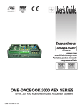
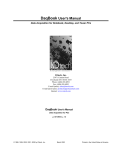
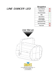
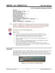
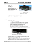
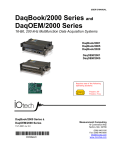
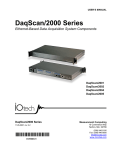
DBK210
32 Channel Digital I/O Carrier Board
for GrayhillTM 70M-Series Mini-Modules
Overview …… 1
Warnings, Cautions, and Tips …… 4
Power …… 5
External Power Watchdog …… 5
Setting Module Banks to Input or Output …… 5
Setting the Local Address …… 6
Software Setup …… 7
Specifications …… 10
Note:
The DBK210 provides: (a) two P2 connectors, (b) one P1 connector, (c) footprints for 32 opticallyisolated Grayhill 70M-Series mini-modules, (d) a 100-pin P4 connector for use with DaqBook/2000
Series Devices and DaqBoard/2000 Series Boards, and (e) 4 removable screw terminal blocks. Each
block supports 8 mini-modules.
This product is not used with:
LogBook
DaqBook/100 Series devices
DaqBoard/100 (ISA-type) Series devices
Reference Notes:
Refer to the DBK Basics section of this manual in regard to calculating system power
requirements.
Chapter 2, System Connections and Pinouts, includes pinouts for P1, P2, P3, and P4
connectors.
Refer to the pinouts that are applicable to your system, as needed.
For a quick comparison of all DBK200 Series boards, refer to the DBK200 Series Matrix.
The matrix is located just before the DBK200 section of this manual.
Refer to the DaqBoard/2000 Series and cPCI DaqBoard/2000c Series User’s Manual
(p/n 1033-0901) or the DaqBook/2000 Series User’s Manual (p/n 1103-0901) for information
pertaining to those products, as needed.
Overview
DBK210 Carrier Board for Grayhill 70M-Series Mini-Modules
The information included in this section, when combined with that found in related DBK sections, should
enable you to set up your desired configuration.
It is important to note that the DaqBoard/2000 Series boards communicate [external from the host PC]
through a 100-pin P4 connector. The P1, P2, and P3 connectors discussed in association with these boards
are subset connectors of the 100-pin P4 connector. DaqBook/2000 Series devices have both a P4
connector and a set of P1, P2, and P3 connectors on the unit. The System Connections and Pinouts chapter
includes pinouts for both types of devices, i.e., DaqBoards and DaqBooks.
DBK Option Cards and Modules
987594
DBK210, pg. 1
DBK210 is a four-bank carrier board for optically-isolated Grayhill 70M-Series mini-modules. Each bank
supports up to eight digital I/O modules. Each bank can be independently set to input or output. The
settings are made via micro-switches on S1 (see next two figures). The Grayhill 70M-Series I/O modules
are industry standard, 5-volt logic level modules.
WARNING
Ensure that hard-wire emergency over-ride circuitry exists for all applications that
make use of dangerous switch-loads. Do not operate such switch-loads unless
emergency over-ride circuitry is present.
Note 1: DBK210 is not used with DaqBoard/2003.
Note 2: DBK210 can be used with DaqBook/200 series and Daqboard/200 series devices;
but should not be used with DaqBook/100 series or DaqBoard/100 series devices.
DBK210 Block Diagram
S1 Detail
The S1 settings for the Banks and the Local Addresses must match the associated settings
in DaqView. This is explained in the Software Setup section, which begins on page 7.
Note: S1 functionality is explained in the following three sections: External Power Watchdog (pg. 5),
Setting Module Banks to Input or Output (pg. 5), and Setting the Local Addresses (pg. 6).
DBK210, pg. 2
987594
DBK Option Cards and Modules
DBK210 boards are typically installed in NEMA-type panels; however, they can be installed on DIN rails.
Separate mounting instructions are included with Rack Mount Kit (part no. Rack-DBK-3) and with DINrail Mount Kit (part no. DIN-DBK-1).
DBK210 is controlled digitally from the Daq device (DaqBook or DaqBoard) as follows:
DaqBook/200 Series Devices – control is through the 37-pin P2 digital port of the DaqBook and one of
two DBK210 P2 connectors.
DaqBoard/200 Series boards [ISA-type] - control is through the 37-pin P2 digital port of the DaqBoard
and one of the DBK210 P2 connectors.
DaqBook/2000 Series Devices – control is achieved by either of the following two methods, but not both
at once:
•
Connect a CA-37-x cable to the P2 connector on the DaqBook/2000 Series device; then
connect the free end of the cable to one of the two P2 connectors on the DBK210.
•
Connect a CA-195 cable to the P4 connector on the DaqBook/2000 Series device; then
connect the free end of the cable to the P4 connector on the DBK210.
DaqBoard/2000 Series boards – control is through the board’s 100-pin P4 connector. Connection of
these boards to DBK210 can be made directly or indirectly as follows:
•
Direct connection can be made from a /2000 Series board’s 100-pin P4 connector to a
DBK210’s P4 connector via a CA-195 cable.
•
Indirect connection can be made using one of the DBK200 Series P4-adapters that includes a
37-pin P2 connector (DBK201, DBK202, DBK203, DBK204, DBK206, DBK209, or another
DBK210). CA-37 cables are used to connect from the P2 connector of the adapter device to
the P2 of the DBK210.
A single Daq-based data acquisition system can support up to 8 DBK210 boards, providing a total of 256
channels. The following figure represents a 64 channel digital I/O system using two DBK210s.
DBK210 boards contain three DB37 connectors, as follows: two P2 connectors for daisy-chaining to other
DBK210s or to other P2-supported devices; one P1 connector for convenient access to the analog input
channels of a 2000 Series DaqBook or a 2000 Series DaqBoard.
DBK210 System in a NEMA Enclosure
In the above figure, the upper DBK210 is connected to a DaqBoard/2000 Series board that has been
installed in an industrial PC. The connection is made from the P4 connector on the installed DaqBoard to
the P4 connector on one of the two DBK210 boards. A 100-conductor CA-195 ribbon cable is used. The
two DBK210s are daisy-chained from a P2 connector on one board to a P2 connector on the other. Each
board has a P1 connector making it possible for analog expansion.
DBK Option Cards and Modules
987594
DBK210, pg. 3
Warnings, Cautions, and Tips
WARNING
Ensure that hard-wire emergency over-ride circuitry exists for all applications that
make use of dangerous switch-loads. Do not operate such switch-loads unless
emergency over-ride circuitry is present.
CAUTION
Turn off power to the host PC and externally connected equipment prior to connecting
cables or signal lines to the DBK. Electric shock or damage to equipment can result
even under low-voltage conditions.
Take ESD precautions (packaging, proper handling, grounded wrist strap, etc.)
Use care to avoid touching board surfaces and onboard components. Only handle
boards by their edges (or ORBs, if applicable). Ensure boards do not come into
contact with foreign elements such as oils, water, and industrial particulate.
Do not confuse connectors. Ensure that you only connect P1 I/Os to P1,
P2 I/Os to P2, and P3 I/Os to P3. Improper connection may result in equipment
damage.
1.
Provide raceways (protective wiring routes) for all external I/O wiring.
2.
Keep external I/O wiring away from ribbon cables.
3.
Keep external I/O wiring away from low-voltage signal wiring.
4.
Provide appropriate strain-relief and physical restraint to ensure that the wiring is held securely in the
intended position, and without strain.
5.
Ensure that all wiring with >50V potential is identified by the appropriate color codes and that
warning labels are clearly visible.
6.
Provide physical protection for the I/O interface board. The level of protection is dependent upon the
board’s operating environment.
Status LED
P1 Connector for
Analog Expansion
(DB37)
Grayhill Min-Module
P4 100-pin
Connector
P2 Connectors for
Digital Expansion
(DB37)
Terminal Block
Power Terminal (5VDC)
Switch S1
Chassis Ground
Partial DBK210
DBK210, pg. 4
987594
DBK Option Cards and Modules
Power
The DBK210 requires an external isolated 5 volt DC power
supply with at least 0.600 amp current capacity. External power
attaches to the DBK210 via on-board screw terminal connections.
The board contains capacitors to filter input noise from the power
supply.
Over-current protection is provided by an on-board 3.0 amp
resettable fuse (F32), which is in series with the 5 volt supply.
Protection from over-voltage and reverse polarity power
conditions is provided by a 6.8V zener diode (D32).
External Power Watchdog
Connecting an External 5 VDC Supply
Set via S1, Switch 1
The External Power Watchdog is governed by the position of
micro-switch 1 on switch S1. The feature allows the user to set
the desired behavior of the digital output latches in the event of a
loss and recovery of the external power supply.
With micro-switch 1 in the Enable position, a loss of external
power will cause the output latches to be reset into a highimpedance condition. Even with a recovery of the external
power, all output modules will be disabled until a write is done to
the data bus. This setting is useful in an application that requires
a serial enabling of output loads.
With micro-switch 1 in the Disable position, a loss of external power will have no effect on the state or
continued control of the output latches. That is, data that is written to the output modules will continue to
be latched as normal. A recovery of the external power would then cause the output modules to reflect the
current state of the output latches. This setting is useful in the case where the operator halts the transfer of
data and turns off the external power on purpose and then wants the system to assume the same state upon
recovery of the external power.
The position of micro-switch 1 has no effect on input modules in regard to external power. While a loss of
external power will result in corruption of the data being read, the data bus will be valid again immediately
upon the recovery of the external power.
Setting Module Banks to Input or Output
Set via S1, Switches 2, 3, 4, & 5
Four of the S1 micro-switches (2, 3, 4, and 5) are used to individually set the digital I/O module banks to
input or output mode. The following table indicates the associations between the micro-switches, banks,
and channels.
MicroSwitch
Affected
Bank
Affected
Channels
2
D
24 thru 31
3
C
16 thru 23
4
B
8 thru 15
5
A
0 thru 7
All eight channels for a given bank must be of the same type, i.e., digital input or digital output. However,
the banks themselves can be set to input or output, regardless of how the other banks are set. For example,
Bank A could be set to digital input and banks B, C, and D could be set to digital output.
The S1 settings for the Banks must match the associated settings in DaqView.
This is explained in the Software Setup section, which begins on page 7.
DBK Option Cards and Modules
987594
DBK210, pg. 5
Setting the Local Address
Set via S1, Switches 6, 7, & 8
Up to eight DBK210 boards can be used in a single Daq system. However, each board contains four
module banks and each bank must have a unique address. This is accomplished with three micro-switches
(6, 7, and 8) on switch S1 and a fixed set of two digits for each bank.
To illustrate, addresses are seen as follows where XXX represents a binary format; e.g., 000; 001, etc as
determined by micro-switches 6, 7, and 8, since each can independently be set to “0”or to “1.”
Bank A, Channels 0 through 7: XXX 00
Bank B, Channels 8 through 15: XXX01
Bank C, Channels 16 through 23: XXX10
Bank D, Channels 24 through 32: XXX11
Assuming we were using three DBK210 boards, for a total of 96 channels, we could use the following
address scheme:
1st DBK210 board, micro-switch 6 set to 0, 7 set to 0, and 8 set to 0, resulting in 000.
2nd DBK210 board, micro-switch 6 set to 0, 7 set to 0, and 8 set to 1, resulting in 001.
3rd DBK210 Board, micro-switch 6 set to 0, 7 set to 1, and 8 set to 0, resulting in 010.
In this example the three boards would have addressing as follows:
DBK210, 1st Board
DBK210, 2nd Board
DBK210, 3rd Board
Bank/Chs
Address
Bank/Chs
Address
Bank/Chs
Address
Bank A
Chs 0 thru 7
00000
Bank A
Chs 0 thru 7
(32 thru 39)
00100
Bank A
Chs 0 thru 7
(64 thru 71)
01000
Bank B
Chs 8 thru 15
00001
Bank B
Chs 8 thru 15
(40 thru 47)
00101
Bank B
Chs 8 thru 15
(72 thru 79)
01001
Bank C
Chs 16 thru 23
00010
Bank C
Chs 16 thru 23
(48 thru 55)
00110
Bank C
Chs 16 thru 23
(80 thru 87)
01010
Bank D
Chs 24 thru 31
00011
Bank D
Chs 24thru31
(56 thru 63)
00111
Bank D
Chs 24 thru 31
(88 thru 95)
01011
Example of Local Addresses for Three DBK210s in a Common Daq System
The Local Address must be unique for each board in the Daq system. In addition, the
board’s address must match the address setting in DaqView. The DaqView aspect is
explained in the Software Setup section, which begins on page 7.
DBK210, pg. 6
987594
DBK Option Cards and Modules
Software Setup
Note: DBK210 is not applicable to LogBook or LogView.
To use DBK210 from within DaqView, you must first configure the DaqView software to match the
hardware setup.
1.
From DaqView’s main window, select the Device pull-down menu.
2.
Select Configure Hardware Settings.
The Digital Option Cards External Connection section of DaqView’s Configure System Hardware
window lists 8 channels (0 through 7) as shown in the following screen image.
3. Select DBK210 from the pull-down list in the Digital Option Cards panel. As seen in the following
figure, the panel is on the right side of screen.
Selecting DBK210 in the Configure System Hardware Window
4. Click <OK>. A DBK210 Configuration Settings window will appear (following figure).
DBK Option Cards and Modules
987594
DBK210, pg. 7
5.
Set S1 micro-switches to agree with the actual settings of the switches on the DBK210 boards. Use
“OFF” to obtain a setting of “0” for each switch and use “ON” to obtain a setting of “1.” A detailed
explanation of address settings is provided on 6.
DBK210 Configuration Settings
6.
Independently set the four banks P20-A, P20-B, P20-C, and P20-D. A checked box indicates that the
associated bank is Digital Output. An unchecked box indicates Digital Input.
7. After S1 and the bank Input / Output settings are complete, click the <OK> button.
8. Select the Digital I/O icon from DaqView’s main window toolbar. The Async Digital I/O window will
appear (following figure).
With the P2 Digital I/O tab selected in the Async Digital I/O window, each active channel has
divisions for the four banks (A, B, C, and D).
Async Digital I/O Window – P2 Digital I/O Tab Selected
In the above screen shot, channel 0 represents one DBK210 board with its four banks: A, B, C, and D.
In this example all four banks are seen as Input. The input determination was made by the physical
positions of micro-switches 2, 3, 4, and 5 on switch S1. Because the 4 banks are set as input, the
DBK210 Configuration Settings dialog box shows the Input / Output boxes as “unchecked.”
When Output is selected, hexadecimal values must be entered in the “O” block for the applicable bank.
9.
DBK210, pg. 8
Upon completion of the configuration click the <Execute> button.
987594
DBK Option Cards and Modules
DaqView’s Channel Setup Tab
In the above figure the 4 Banks for one DBK210 card are listed in the CH column as:
P2 0-A, P2 0-B, P2 0-C, and P2 0-D.
DBK Option Cards and Modules
987594
DBK210, pg. 9
DBK210 – Specifications
Name/Function: Carrier Board for GrayhillTM 70M-Series Mini-Modules
Module Capacity: 32 Grayhill 70M-Series Mini-Modules per board
Cable (optional): CA-37-×
DC Input Fuse: 3.0A, resettable type
DC Input Connector: Non-removable screw terminal, (+5 VDC, GND)
Power Requirement: 5 VDC, ±5%. 0.600 amp minimum.
Operating Environment:
Temperature: 0°C to 70°C
Relative Humidity: 95% RH, non-condensing
Connectors:
P1 – One P1 (DB37) connector provides for Analog input expansion via a CA-37-x cable.
P2 – Two P2 (DB37) connectors provide for digital expansion via a CA-37-x cable.
P4 – 100-pin connector provides for connection to the P4 connector of a DaqBook/2000
Series device, DaqBoard/2000 Series board, or cPCI DaqBoard/2000c Series board.
P4-to-P4 connection is made via a CA-195 cable.
Screw Terminals – 4 removable screw-terminal blocks. Each block has 16 connections for 8
mini-modules, i.e., 2 connections (+/-) per module.
Isolation:
Channel-to-System: 250 V
Channel-to-Channel: 250 V
Note: Specifications are subject to change without notice.
DBK210, pg. 10
987594
DBK Option Cards and Modules