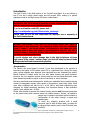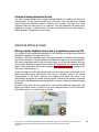
1
Petit Crouton (a.k.a. PC) v2.0
Entry Range Illuminated Saber Controller – User’s manual
© Erv’ - Plecter Labs – v 2.0 – January 2012
[email protected]
http://www.plecterlabs.com
We spent a lot of time writing this manual to ensure all the important
information is provided for proper use of that board. If you are new to saber
building, to the use of Plecter Labs boards, or simply to electronics in
general, we highly recommend you print a copy of that document and keep
it with you during the whole process of installing PC in your hilt.
Modification, copies or distribution of this document is strictly prohibited
© Plecter Labs / Erv’ Plecter 2005-2012
Plecter Labs is in no way affiliated, associated, licensed or endorsed by Lucasfilm Ltd., Industrial Light and Magic or any of
their associates.All brands and trademarks listed are the exclusive property of their respective owners.
2005-2012
1
Index
PETIT CROUTON (A.K.A. PC) V2.0
1
INTRODUCTION
Sound section
Petit Crouton V2.0 Features & Maximum Ratings
TOOLS AND PARTS REQUIRED TO INSTALL/OPERATE THE MODULE
SD CARD CONTENTS, SOUND BANKS AND SLOTS
BOARD OVERVIEW
USER’S NOTES
WIRING AND OPERATING THE MODULE
General Power Switch & Recharge Port
General wiring
USER’S NOTES
Animated Accent LEDs
Calculating resistors for LEDs
MAIN CONFIGURATION FILE
PARAMETERS AND FINE TUNING THE SABER
CLASHES & SWINGS SELECTION MODES
3
3
4
5
6
7
8
9
9
11
11
12
12
14
15
18
ADVANCED WIRING & USAGE
18
WIRING A TACTILE FEEDBACK MOTOR AND A PROGRESSIVE POWER ON LED
WIRING A GENERAL POWER-ON INDICATOR / ACCENT LED
WIRING A FLASH ON CLASH™ (FOC™) LED / DIE
ACCENT LEDS SEQUENCER
Stages & Delays
DEEP SLEEP FLASHING LED
Mute On The Go™
TROUBLESHOOTING & FAQ
18
21
22
24
24
26
26
27
Plecter Labs is in no way affiliated, associated, licensed or endorsed by Lucasfilm Ltd., Industrial Light and Magic or any of
their associates.All brands and trademarks listed are the exclusive property of their respective owners.
2005-2012
2
Introduction
The Petit Crouton is the little brother of our Crystal Focus Board. It is very similar to
the CF but has a single sound banks and two accent LEDs, making it a perfect
midrange sound fx and high-power LED driver combo board.
Warning : You’ve just acquired an electronic board containing parts
sensitive to ESD. Final wiring & assembly is under responsibility of the user
with the appropriate tools and ESD protection.
If you’re not familiar with ESD, please visit :
http://en.wikipedia.org/wiki/Electrostatic_discharge
Plecter Labs can not be held responsible for improper use or assembly of
the Petit Crouton board.
Warning : High-power LEDs (such as the Luxeon brand LED, which is
mentioned in this document) are extremely bright. They are considered
"class 2 lasers"! You should neither look directly to the beam nor point
someone with it when the blade is not attached to the hilt, just like a
powerfull lamp or flashlight. Plecter Labs could not be held responsible for
any bad use of high-power LEDs.
To avoid injuries and retina damage due to the high brightness of those
high-power LEDs, simple “emitter plugs” can be built using a piece of blade
tubing ended with some decorative greeblies.
Sound section
The Plecter Labs sound board is unique. It has been developed in the purpose of
improving the quality of DIY sabers sound FX in a significant way. During too many
years, sound modules were obtained from sacrificed toys and remained low quality.
Master Replica FX sabers broke the line with better sounds and good dynamics.
However, the low resolution motion sensors used as well as closed electronics made
those boards impossible to adjust in term of sensitivity or sound contents.
We have monitored several attempts for building an embedded sound module playing
custom & changeable sounds, often based on chipcorders. Using bulky parts, those
were often unreliable and hard to fit in a hilt. Not to add those chipcorders were
designed for digital answering machines, and therefore feature a bad restitution
quality (voice sample rate – 8 KHz).
Plecter Labs decided to process the internal motion sensors and the sound generation
on the same board which requires some non-volatile memory. Second, we needed a
simple way to upload or download sound contents or
configuration of the saber through a simple and
standard way.
To avoid any plugging problem with a small
connector and an easy-to-loose cable, we opted for
a high-end flash memory card in the SD format (now
microSD).
Plecter Labs is in no way affiliated, associated, licensed or endorsed by Lucasfilm Ltd., Industrial Light and Magic or any of
their associates.All brands and trademarks listed are the exclusive property of their respective owners.
2005-2012
3
Inserted in a USB card reader like the one we sell, the card is seen as a USB storage
key and it takes a few seconds only to transfer files to or from the card, on Mac or PC,
without the need of any custom piece of software.
Petit Crouton V2.0 Features & Maximum Ratings
-
-
Dimensions: 48x23.5x7.5 mm (with the microSD card).
Power supply: 5.5 to 11 V / 2.5A (with the High-power LED). 2 li-ion cells
(18650 or 14500) batteries recommended.
Idle current consumption : 3 mA (deep sleep mode)
2 A high-power LED drive
Speaker: 4 to 8 ohm.
Audio output Power : 2W
Accent LEDs: 2
32 stages sequence with stop and loop instructions (using either 0 or 65535 for
the delay)
Accent LEDs pad current source: 18 mA max per pad
Handles momentary or latching for blade activation
Blaster Blocking & Lockup Fx
Blade Flickering Fx
Blade Shimmering on Clash
Anti Power Off technology (A-POP™)
Foc™ Flash on Clash™
WAV file support
12 bit sound
SD card support: up to 2GB, FAT16 or FAT32 (beta). Sandisk and Kingston
brands preferred.
Hum resume: defines if you come back to where the hum has been interrupted
or not. Interesting for certain hums. Not sample accurate but resumes the hum
in a ballpark of 11ms from where it's been interrupted by a fx sound
Anti power off delay (offd) : variant of our Anti Power Off technology (APOP)
use an adjustable delay when cycling the the activation switch.
Led current parameter now takes mA. To get 2A you would enter 2000, for
1.5A 1500 etc
Motion sensing thresholds now go up to 1023 (ls, hs, lc) : multiply your former
CF configurations by 4.
General sensitivity (i) is now an integer between 0 and 99. Same kind of value
than on CFv5. Previously entered as float number (0.65) but is now 65.
Wiring is very similar to current CF, down to the accent LEDs location and FoC
pad.
Shorter than PC 1.6
Mute on the go
Plecter Labs is in no way affiliated, associated, licensed or endorsed by Lucasfilm Ltd., Industrial Light and Magic or any of
their associates.All brands and trademarks listed are the exclusive property of their respective owners.
2005-2012
4
Tools and Parts required to install/operate the module
-
an ESD safe soldering station & soldering wire (60/40, 1mm OD or eq.)
pliers (flat and cutting)
a Digital Multimeter / DMM (strongly advised, so useful)
a latching or momentary switch for the blade ignition, and a momentary switch
for the auxiliary switch.
wire & heat shrink
rechargeable Batteries
recharge port (canon 2.1mm socket)
appropriate Battery charger
a USB SD card reader accepting micro SD card or a regular SD card reader with
a micro to regular SD card adapter.
a computer
a digital audio editor software handling WAV files if you wish to create your
own sound fonts.
Plecter Labs is in no way affiliated, associated, licensed or endorsed by Lucasfilm Ltd., Industrial Light and Magic or any of
their associates.All brands and trademarks listed are the exclusive property of their respective owners.
2005-2012
5
SD card contents, Sound Banks and Slots
Sounds are stored in the WAV format (16 bits, 22050 samples per second). Despite
the module uses a 12 bit sound output, we kept the 16 bit format of the sound font,
therefore ensuring immediate compatibility with CF sound fonts. You can now drop
the contents of a CF sound bank directly onto the root directory of the SD card for the
PC 2.0. It will only use the files necessary and ignore the rest.
WAV sound files must comply with the format above or they will be skipped
during the boot, leading to sound gaps or board failure.
Petit Crouton has a single sound bank, with all the files (including configuration files)
stored in the root directory of the SD card. The sound content of a bank is called a
Sound Font.
A sound bank has 26 sound slots split as below:
a boot sound (boot.wav)
a power on sound (poweron.wav)
a power off sound (poweroff.wav)
continuous humming (hum.wav)
8 clash sounds (clash1.wav to clash8.wav)
8 swing sounds (swing1.wav to swing8.wav)
4 blaster blocking sound (blaster1.wav to blaster4)
a blade lockup sound (lockup.wav)
force sound (force.wav)
When the power supply voltage is applied to the board, our board “boots” and plays a
little logo sound to notify the user, just like a digital camera. This little logo makes
sure the Petit Crouton Saber Core started properly and it gives a special identity to the
saber and to the loaded sound font. This sound can be of course customized. If the
boot sound boot.wav is not on the SD card, a little beep is played instead. If you
don’t want any sound when powering the module, create a WAV sound file with 100
ms of silence.
The sounds must be all there on the SD card and be named properly (lower case) to
have the module operating properly. Same thing for the configuration files (.txt).
We advise the user to keep all its sound and configuration files in specific folders on
the hard disk on the computer so that changing the saber’s contents remains easy.
Use some explicit naming of the folders so that you can easily remember what the
sound
font
and
configuration
files
are
doing,
for
instance
[very_sensitive_dark_lord_saber].
Plecter Labs is in no way affiliated, associated, licensed or endorsed by Lucasfilm Ltd., Industrial Light and Magic or any of
their associates.All brands and trademarks listed are the exclusive property of their respective owners.
2005-2012
6
Creating Your Own Sounds
It’s a great personal satisfaction to build up your own soundfont. However, it’s not so
easy. Please read our online tutorial about that particular topic.
Installing a Sound Font on the SD card
Although editing the configuration files (text files) can be done directly
onto your microSD card, changing the SOUND FILES (.wav of ANY kind)
requires you to format the microSD card! This is not a recommendation, it
is A REQUIREMENT: YOU MUST FORMAT THE SD CARD prior to changing
any sound files!
1. First thing: backup the SD card on the hard disk. Easy to do, however most
people don’t bother doing so and end losing their
initial configuration.
2. Unzip the sound font archive in a directory of
your hard disc.
3. Take all the WAV sounds. If the sound font zip
archive comes configuration files that are
supposed to match the theme of the sound font,
you can take it as well, but make sure the
settings won’t harm anything (especially the
high-power LED current).
4. Copy the files in desired sound bank and
overwrite the files
5. Copy the whole SD card (Ctrl+a, Ctrl+c) to a
temporary folder of the hard drive.
6. Format the SD card in FAT (FAT16 or FAT32)
7. Select the whole content of the temporary
directory on the hard drive and copy it in one run
to the SD card (Ctrl+a, Ctrl+c, Ctrl+v on the SD
drive)
If you wish to try different sound fonts quickly, copying back and forth all the files will
soon be boring and time consuming. Start by configuring your board to use bank1.
Then make a temporary file structure of the SD card that has only the bank1 directory
and nothing else. Use that directory to test the different sound fonts. This way you
will transfer only a limited number of files. Once the fonts have been selected, you can
store them in the different sound banks and start adjusting the parameters.
Board Overview
Plecter Labs is in no way affiliated, associated, licensed or endorsed by Lucasfilm Ltd., Industrial Light and Magic or any of
their associates.All brands and trademarks listed are the exclusive property of their respective owners.
2005-2012
7
User’s Notes
Plecter Labs is in no way affiliated, associated, licensed or endorsed by Lucasfilm Ltd., Industrial Light and Magic or any of
their associates.All brands and trademarks listed are the exclusive property of their respective owners.
2005-2012
8
Wiring and Operating the Module
The board must be powered with an appropriate battery pack. We highly recommend
the use of good quality li-ion battery packs made of 14500 or 18650 cells and
including protection PCBs. The AW brand makes superior quality batteries while
the Ultrafire remains a cost effective solution.
Unless you have a convenient way to open the hilt and access the inside of the saber
(Graflex base for instance), we strongly recommend the use of a directly connected
battery pack (with a “recharge port”) vs. removable cells. Moreover, for dueling
sabers, directly wired battery packs have more reliable connections compared to
spring action battery holders.
A 2-cell li-ion will provide a nominal voltage of 7.4V to the board. The board isn’t
compatible with a 3-cell solution without some modifications of the electronics.
Ni-MH battery packs are simply not recommended since they have a bigger energy
storage/volume ratio and cost of li-ion cells isn’t an issue anymore.
General Power Switch & Recharge Port
Despite the PC board has a very low idle current use (3mA) when the blade is off and
board is in deep sleep mode, long term storage of the hilt on a shelf or display case
requires the electronics to be fully shut off. To avoid the use of an additional general
power switch, we use the recharge port for that very purpose. A pin 2.1 mm “Canon”
socket is a popular choice. Two of those pins are connected when nothing is inserted
in the socket. Contact is disrupted when a plug is inserted.
Along the years, the “kill key” technique has been developed: a fake plastic plug is
decorated to look like an actual part of the hilt. When inserted, it cuts the power
supply to the board in the recharge port. Of course, the port recharges the internal
battery pack when an actual charger plug is inserted.
Below, 2 examples of decorative kill keys (February 2006 and July 2010)
The Kill Key must be made out of a non-conductive material (PVC, Nylon etc). The left
picture above shows a kill key made out of a sacrificed male plug (metal) but it’s
Plecter Labs is in no way affiliated, associated, licensed or endorsed by Lucasfilm Ltd., Industrial Light and Magic or any of
their associates.All brands and trademarks listed are the exclusive property of their respective owners.
2005-2012
9
provided only as a reference picture and plastic should be used as a rule of the
thumb.
Here’s the usual wiring of the recharge port. Please note that not all recharge ports
have the exact same pin out. User must understand the principle of wiring a recharge
port and must be able to identify the different pins of a socket.
The idea is fairly simple: the positive of the battery pack goes to the recharge port
central pin (referred as tip) and to the positive of the board. It’s not affected by the
kill key. The negative of the battery pack goes to the pin of the recharge port that is
connected to the outer sleeve of the socket. The last pin, referred as switched
negative pin and goes to the negative of the board.
When nothing is inserted in the port, the negative of the battery pack is internally
connected to the switched negative tab, hence powering the board. When a Kill Key is
inserted in the port, the negative of the board is no longer connected to the negative
of the battery pack: the board is fully powered down. When a charger plug is inserted
in the recharge port, the charging voltage is reaching both leads of the battery pack
while the negative of the board is still unconnected from the circuit, preventing
damages to the electronics and ensuring only the battery pack is connected to the
charger for proper charge.
In the previous picture the green-black drawn switched doesn’t need to be wired per
say, it only illustrates the recharge socket internal switch.
Plecter Labs is in no way affiliated, associated, licensed or endorsed by Lucasfilm Ltd., Industrial Light and Magic or any of
their associates.All brands and trademarks listed are the exclusive property of their respective owners.
2005-2012
10
General wiring
The board doesn’t need so many connections for basic operation. Aside of the
recharge port / power supply detailed above, only a pair of switches, the high power
LED and the speaker are required to be soldered to get 90% of the features the PC
board proposes.
NEVER change the high-power LED while Petit Crouton Saber Core is in idle
mode. If you need to install another high-power LED (changing the color for
instance) you must totally power the saber off.
User’s Notes
Plecter Labs is in no way affiliated, associated, licensed or endorsed by Lucasfilm Ltd., Industrial Light and Magic or any of
their associates.All brands and trademarks listed are the exclusive property of their respective owners.
2005-2012
11
Animated Accent LEDs
There are many ways to “pimp” your saber hilt using additional small LEDs further
referred in this document as Accent LEDs.
Petit Crouton features a 32 stage sequencer that allows the user to setup a blinking
animated sequence for up to 2 LEDs. The board outputs 3.3V / 18mA max per accent
LED pad. User must ensure the used accent LEDs have a forward voltage (Vf) lower or
equal to 3.3V.
On the picture above, the red arrows point to the positive pads of the accent leds, use
small gauge wire to send those signals to the positive of the LEDs. Flat/Ribbon cable
can be very handy for that purpose. Then both negatives of the LEDs return to a
single pad pointed by the blue arrow (ground return).
The resistor pads on the PC2 are pre-bridged.
resistor for the accent LEDs
You will need to use an external
Calculating resistors for LEDs
R = (Vsupply – Vled) / LedCurrent
In our case, Vsupply is the voltage the board provides to power the accent LEDs, ie
3.3V. The Vled is the forward voltage of the LED, usually referred as Vf in the
datasheet. The led current has to be decided by the user, depending on the
brightness and the maximum rating of the used LED. 5 to15 mA are fairly common for
most accent LEDs.
As an example, let’s consider a 1.6 volt LED (red) at 10 mA
R = (3.3 – 1.6) / 0.01 = 170 ohm ( 150 ohm in the classic E12 resistor serie)
Plecter Labs is in no way affiliated, associated, licensed or endorsed by Lucasfilm Ltd., Industrial Light and Magic or any of
their associates.All brands and trademarks listed are the exclusive property of their respective owners.
2005-2012
12
Be sure not to drive too much current in the LED (18 mA max). If you wish a good
brightness with a low current, use high efficiency LED (generally coming in a
transparent “crystal” coating).
Please see further in this document for the sequencing of the accent LEDs.
Plecter Labs is in no way affiliated, associated, licensed or endorsed by Lucasfilm Ltd., Industrial Light and Magic or any of
their associates.All brands and trademarks listed are the exclusive property of their respective owners.
2005-2012
13
Main Configuration File
The config.txt configuration file is a simple text file to be edited with windows
notepad.
It is composed of 26 parameters that must all be present in the file. Otherwise, the
module will use default parameters.
The text file accepts comments on a stand alone line (not mixed with a parameter
line). The comment symbol is the C language double slash ‘//’ as the very first
characters of the line.
To modify the file, insert the SD card in the USB card reader, and then browse the
contents with windows file explorer (on E: for instance). Double-click on file
config.txt : the notepad opens. You can directly save the file on the SD card. Once
the configuration is over, simply remove the card from the reader after having it
“ejected” (right click on the reader device in windows explorer, contextual menu,
eject). Put the card back in the saber and test you new setup!
The configuration file MUST BE LESS than 512 bytes. If the size is bigger, the file
will be skipped without further analysis and defaults parameters will be used. The
basic configuration file of Petit Crouton is about 220 bytes, with a few comment lines
for an easier reading. Make sure not to add too many comments in the file. If you are
not sure of the file size, check it in Windows file Explorer, with a right click on the file,
then “properties” in the contextual menu.
Make sure you have no space characters at the beginning of the line, or
between the ‘=’ sign and the value of a parameter.
Plecter Labs is in no way affiliated, associated, licensed or endorsed by Lucasfilm Ltd., Industrial Light and Magic or any of
their associates.All brands and trademarks listed are the exclusive property of their respective owners.
2005-2012
14
Parameters and fine tuning the saber
The configuration file includes a set of parameters dedicated to the sound section of
the controller and the gestural / motion detection (both being linked). A second set of
parameters handles the behavior of the high-power LED. Some parameters influence
both categories, since visual and sound effects are in tight relationship intrinsically. All
parameters are lowercase.
Certain parameters involve time / duration / delay. We tried to normalize
those parameters to a single unit: a multiple of 2ms. Unless otherwise
indicated, that’s what is used to define those timing parameters and it
matches the internal clock of PC.
Motion & Gesture detection parameters :
Swings and clashes are separated using 3 thresholds. A swing motion must exceed ls
(low swing) and must remain under hs (high swing). A clash must simply exceed lc
(low clash).
It’s important to maintain a dead-zone between hs and lc to maximize the quality of
the motion detection.
Default parameters have been setup for you and usually, only the “i” parameter has to
be touched up.
However, some special cases can be considered:
_ The saber is not sensitive enough to the swing (placement in the hilt too close
to the spinning center, spinning style etc) : decrease parameter ls of one point
of two. Don’t decrease ls too much or undesired swing sounds will be
triggered.
_ When the saber cuts the air too fast, the swing is not triggered (it’s in the
dead-zone). Increase a little bit parameter hs(or reduce the speed of your
swings).
_ The saber often produces a clash sound when the user executes a swing:
parameter hs is probably too high and too close to parameter lc. If the clash
sensitivity is correct, decrease parameter hs.
_ The saber is not sensitive enough to clashes: decrease parameter lc.
_ The user wants the clash to happen only when blade is smacked very hard:
increase lc (keep it under 1023).
Rule of the thumb for a proper configuration process: modify only a single parameter
at once and work separately on clash and swing parameters. Fine tuning the module
might take some time, but a good configuration will lead you to a very satisfying
interaction with the saber.
Gesture flows & priorities :
Our gesture analysis is so fast that sounds could be chained one after the other at
light speed! We therefore have to slow down the module because too many swing
sounds played in a short time are not so realistic. For that reason we implement
gesture flow limiters for swing and clash sounds.
Plecter Labs is in no way affiliated, associated, licensed or endorsed by Lucasfilm Ltd., Industrial Light and Magic or any of
their associates.All brands and trademarks listed are the exclusive property of their respective owners.
2005-2012
15
Clash sounds generally have the priority over all other sounds except in the following
cases:
- lockup is engaged : no other sound will be triggered until the aux. switch is
released
- a blaster sound is triggered. Swings cannot interrupt it. A clash can interrupt it.
A clash sound can interrupt a swing sound even if the swing flow limiter is engaged
(just after a swing was triggered).
A clash sound cannot interrupt a previously triggered clash sound if the clash flow
limiter is still engaged (delay for triggering another one hasn’t expired).
A swing sound cannot interrupt a previously triggered swing sound if the swing flow
limiter is still engaged (delay for triggering another one hasn’t expired).
A swing sound can never interrupt a clash sound if the clash flow limiter is still
engaged, and whether or not the swing rate limiter is engaged.
If the clash flow limiter has expired, and even if the clash sound is still playing, a
swing sound can interrupt it.
swing [0-500]: swing rate flow limiter. Delay during which swings cannot be
furthermore triggered.
clash [0-500]: clash rate flow limiter. Delay during which clashes cannot be
furthermore triggered.
Sound parameters :
vol [0-4] : digital volume setup. 0 mutes the sound output, 4 is the
maximum volume.
shmrd [10-500]: duration of the shimmering effect of the high-power LED
during a clash. Make sure this duration is not too much longer than the
associated sound to keep a nice result.
shmrp [5-25]: periodicity of the light bursts during the clash effect. A slow
period will produce tight bursts.
shmrr [0-25]: random value applied to the periodicity of the light burst
during a clash effect. Allows having bursts that are not regularly spaced in time
which increases the realism. For instance, a period shmrp of 20 and a random
value shmrr of 10 will produce a period between two bursts varying between
20 and 30 (ie 40 and 60 ms).
switch [0-2]: selects if the saber is activated by a normally-open or a
normally-closed switch. Certain “push-on push-off” switches are more practical
and more reliable when released for activating the saber. Other switches might
simply have an “inverted” logic (normally closed contact). When switch is set
to 1, the saber lights up when the electrical contact of the switch is closed and
conversely when switch is set to 0. If you wish to use a momentary switch
for the blade activation, set switch to 2.
offp [0-1]: Anti power off protection (A-POP). To avoid accidentally
powering off the saber, especially when using a momentary button for
activation, we added a power off protection. When this parameter is set to 1,
Plecter Labs is in no way affiliated, associated, licensed or endorsed by Lucasfilm Ltd., Industrial Light and Magic or any of
their associates.All brands and trademarks listed are the exclusive property of their respective owners.
2005-2012
16
the user must press the activation button and confirm with the auxiliary button.
It is not necessary to press both buttons at the same time, keep the activation
switch pressed first, then press the auxiliary switch: the blade goes off.
qon [0-3000]: “quick-on”. Allows having the blade ignited in a specific
amount of time rather than matching the duration of the power on sound. This
parameter is specified in milliseconds (ms), and should not exceed the
duration of any power on sounds.
qoff [0-3000]: same thing as above, but for the blade retractation. Also in
ms.
lockup [0-1000]: our module features an auxiliary switch to trigger
additional sound/visual effects. A short pressure on the switch generates the
blaster effect (the saber blade stops a blaster ray), plays one of the blaster
sounds. A longer pressure (maintained) triggers a blade lockup effect: while the
switch is pressed, the sound lockup.wav is played in loop with some
shimmering applied to the high-power LED. The parameter lockup specifies
the duration of the delay before triggering the lockup effect. A short value (50
to 100) will trigger the effect almost immediately: to trigger a blaster effect, the
user will have to release the button quickly. Conversely, a higher value will
leave more time to produce a blaster blocking feature.
focd [0-500]: Flash on Clash™ (FoC™) duration. Used when an extra LED
die is wired to the board with a Power Xtender™ circuit and the Flash on
Clash™ Pad.
focp [5-25]: periodicity of the light bursts during the Flash on Clash™
effect. A slow period will produce tight bursts. Similar to the shmrp parameter.
focr [0-25]: random value applied to the periodicity of the light burst during
a Flash on Clash™ effect. Similar to shmrr but applied to FoC™.
focfs [0-511]: defines the overall strength of the FoC LED die
offd [0-3000]: adds a delay to the power off when changing the state of the
activation switch. Max value = 3000 = 6 seconds
resume [0-1] hum resume : defines if you come back to where the hum has
been interrupted or not. Interesting for certain hums. Not sample accurate but
resumes the hum in a ballpark of 11ms from where it's been interrupted by a fx
sound
High-power LED parameters :
led [0-2000]: defines the current of the LED up to 2A. A value of 750
matches 750 mA, 1000 gives 1A. Calculation of the value is in actual milliamps
flks [0-20]: speed of the energy variation / flickering effect of the blade. A
high value produces a damaged saber effect while a small value generates
subtile energy changes. The value 0 disables the effect (static blade).
flkd [0-100]: depth (in %) of the energy fluctuation effect, i.e. the the
range over which the LED brightness will be affected during the effect. A low
value does not modify the energy very much while a high value « digs » big
steps of light intensity. To be used with the parameter flks.
Plecter Labs is in no way affiliated, associated, licensed or endorsed by Lucasfilm Ltd., Industrial Light and Magic or any of
their associates.All brands and trademarks listed are the exclusive property of their respective owners.
2005-2012
17
Clashes & Swings Selection Modes
The Petit Crouton boards have a single random method for selecting the clash and
swing sounds. It’s the same as mode 3 on a CF board: this is an improved random
mode referred as RandomX mode or “Bubble Sort” random. The idea is to avoid
triggering twice the same sound in a sequence. This new algorithm will make sure a
sequence (8 swings / 8 clashes) does not have any duplicate, but you might still get a
double between 2 sequences, in rare cases.
Advanced Wiring & Usage
Wiring a tactile feedback motor and a progressive power On LED
It is possible to wire additional peripherals on our controller and make them follow the
fluctuations applied to the high power LED.
Therefore, a little force feedback motor (like the ones used in cellphones) and a power
on LED can be added. Those peripherals will behave the same way as the high-power
LED does: progressive fade in and out during power on/off and perturbation during a
clash, blaster blocking or blade lockup effects. The peripherals are connected on the
output of the high-power LED current regulator but return to ground instead of the
high-power LED negative (L-).
Please note that due to the mechanical nature of the motion sensor used (made out of
small steel balls moving with motion) the use of a rumbling motor is not always
recommended. It can work; however, the installer must insure the motor is as
mechanically decoupled as possible from the board, otherwise the vibration generated
by the motor will permanently activate the motion sensors, leading to undesired swing
fx sounds.
No extra wiring pad has been provided for wiring those additional peripherals, just
solder the positive wires (in yellow on the wiring diagram below) on the high-power
LED positive pad (L+) or on the side of the coil.
Plecter Labs is in no way affiliated, associated, licensed or endorsed by Lucasfilm Ltd., Industrial Light and Magic or any of
their associates.All brands and trademarks listed are the exclusive property of their respective owners.
2005-2012
18
Calculation of the power-on LED resistor
The power-on LED is not current regulated, it just takes the voltage applied to the
high-power LED running at its nominal current. We therefore need to limit the current
in the power on LED, as well as in the force-feedback motor.
The calculation of the resistor depends on the forward voltage of the high-power LED,
which varies with the current used and the LED color, the forward voltage of the
accent LED and the current flowing in it.
Example
A classic 3 or 5 mm LED (red, green or yellow) has a forward voltage of 1.6 to 1.8
volts and can take up to 20 mA.
For a red, red-orange or amber luxeon III LED the forward voltage is about
2.9V. Let’s take for instance a red power-on LED (1.6V) at 15 mA.
RPower-on LED = (Vluxeon – VPower-on LED) / IPower-on LED
RPower-on LED = (2.9 – 1.6) / 0.015 = 86 Ω
Which leads to 82Ω or 91Ω in the E12 resistor serie.
For a white, blue, green or cyan luxeon the forward voltage is about 3.7 V.
Let’s take for example a green LED (1.8V) at 15 mA.
RPower-on LED = (Vluxeon – VPower-on LED) / IPower-on LED
RPower-on LED = (3.7 – 1.8) / 0.015 = 95 Ω
Which leads to 91Ω or 100Ω in the E12 serie.
Calculation of the force-feedback motor resistor
There are too many various sorts of motors
to determine a specific resistor. The motors
we sell are designed to work in the 1V to 2V
range and the current they take increases
very quickly when the power supply voltage
increases due to the non-centered weight
that produces the rumbling effect.
We can however take 1.5V as a base voltage
with a 100 mA maximum current to avoid
too much current flowing in the high-power
LED driver and limit heating.
For a red, red-orange or amber luxeon LED the forward voltage is about 2.5V.
Rmotor = (Vluxeon – Vmotor) / Imotor
Rmotor = (2.5 – 1.5) / 0.1 = 10 Ω - ½ watt
For a white, blue, green or cyan luxeon the forward voltage is about 3.7 V.
Rmotor = (Vluxeon – Vmotor) / Imotor
Rmotor = (3.7 – 1.5) / 0.1 = 22 Ω - ½ watt
Plecter Labs is in no way affiliated, associated, licensed or endorsed by Lucasfilm Ltd., Industrial Light and Magic or any of
their associates.All brands and trademarks listed are the exclusive property of their respective owners.
2005-2012
19
For an unknown motor, experimentation is the key, starting for instance with a ½
watt 100 or 150Ω resistor and an amp-meter to find out the supply voltage of the
motor within the limit of the max current used (100 mA max). The best solution is to
power the motor with a regulated power supply and to increase slowly the voltage
while monitoring the current and when the current and voltage are found, you can go
back to the above formula. Be sure to use at least a ½ watt resistor in all cases.
An easy workaround is to use a multiturn trimming potentiometer of 100Ω
Ω
or 1kΩ
Ω. This makes possible to adjust the speed with accuracy.
User’s Notes
Plecter Labs is in no way affiliated, associated, licensed or endorsed by Lucasfilm Ltd., Industrial Light and Magic or any of
their associates.All brands and trademarks listed are the exclusive property of their respective owners.
2005-2012
20
Wiring a general Power-On Indicator / Accent LED
It’s is sometimes useful (or good looking) to have a LED lighting up as soon as the kill
key is removed. Of course, 1 of the 2 accent LEDs could still blink as idle mode
indicator, but a permanently on LED could be nice to simply indicate the battery pack
is working properly. This is also very nice to have indicator lighting up the internal ring
of a chromed anti-vandal switch.
The PC board provides a regulated 3.3V pad for that purpose, shown in purple in the
illustration below.
Plecter Labs is in no way affiliated, associated, licensed or endorsed by Lucasfilm Ltd., Industrial Light and Magic or any of
their associates.All brands and trademarks listed are the exclusive property of their respective owners.
2005-2012
21
Wiring a Flash on Clash™ (FoC™) LED / Die
PC v2.0 features an additional pad to drive a Flash on Clash™ effect. With the
emerging technology of multi-die high-power LEDs, certain dice can be used to light
up the blade, while a remaining die can add some more light (possibly with a different
color) when a clash is triggered. Depending on the configuration file, the FoC™ can
also be triggered when blaster blocking, and lockup events are registered.
The FoC™ pad is only a 3.3V remote control pad and cannot drive any power. Hence,
it controls a Power Xtender™ micro board in order to drive an additional LED die.
Moreover, the FoC™ isn’t static but has also its own shimmer parameters in the
configuration files, which allows the generation of very vivid Flash on Clash effects
(focp, focr and focs parameters).
The drive of the LED die involved in the FoC™ isn’t current regulated, so the
appropriate resistor must be included in the Power Xtender™ circuit to limit the
current. Also, user must be concerned about the current used by the FoC™ die, the
overall current used by the complete setup, and the current the battery pack can
provide. Exceeding the capacity of the battery pack, or its discharge rate could lead to
battery deterioration or explosion.
Example of use :
Let’s consider the drive an extra white die at 1A for the FoC. Forward voltage of that
die is around 3.7V.
Required resistor for the FoC circuit :
R = (Vpack – Vf die) / FoC current
R = (7.4 – 3.7) / 1 = 3.7 ohm
Wattage of the resistor :
P = RxI2 = 3.7 watt.
Since the FoC circuit is only active for a short time (maximum 10 seconds during a
lockup), it’s acceptable to use a 3W resistor in the example above.
If the user wants to drive an accent LED out of the FoC pad (and not a high-power
LED die), this can be of course achieved without a Power Xtender board, just like any
accent LED. The pad outputs 3.3V and 18 mA maximum.
Plecter Labs is in no way affiliated, associated, licensed or endorsed by Lucasfilm Ltd., Industrial Light and Magic or any of
their associates.All brands and trademarks listed are the exclusive property of their respective owners.
2005-2012
22
Wiring Diagram for Flash on Clash™ (FoC™)
Flash on Clash™ (FoC™)
User’s Notes
Plecter Labs is in no way affiliated, associated, licensed or endorsed by Lucasfilm Ltd., Industrial Light and Magic or any of
their associates.All brands and trademarks listed are the exclusive property of their respective owners.
2005-2012
23
Accent LEDs sequencer
2 accent LEDs can produce 4 patterns; we limited the sequencer to 32 stages.
The working principle of the sequencer is to put the LEDs in a given pattern/state
during a certain time (delay). Once the delay is over, a new pattern is output and so
on for the 32 stages before looping to the first one.
The main LED sequence is described for each sound bank in the leds.txt text file.
Simply open the file with window notepad to modify it, directly on the SD card or on
the hard disk.
Here is an example of an actual leds.txt file.
Stages & Delays
The delay between each state can be different for each “state” line, it’s not necessary
to have a pattern evolution with a constant timing. A value of 0 for a “delay” line will
stop the sequencer. Hence, it’s possible to have an accent LED animation when the
Plecter Labs is in no way affiliated, associated, licensed or endorsed by Lucasfilm Ltd., Industrial Light and Magic or any of
their associates.All brands and trademarks listed are the exclusive property of their respective owners.
2005-2012
24
saber starts, and the animation stop at the end of the 32 stages (or before) when a 0
delay is found in the file.
When setting random to 1 the sequencer will generate a random pattern at each
stage of the sequence, ideal for a changing or non conventional animation. The delays
will remain the ones specified in the sequence.
A delay of 65535 will loop the sequence. It’s of course possible to use a LED output to
drive an accent LED AND the remote control wire of a power xtender board to drive
an additional peripheral requiring more power than what the accent LED pads can
offer.
Plecter Labs is in no way affiliated, associated, licensed or endorsed by Lucasfilm Ltd., Industrial Light and Magic or any of
their associates.All brands and trademarks listed are the exclusive property of their respective owners.
2005-2012
25
Deep Sleep flashing LED
It’s also possible to use one of the 2 accent LEDs to indicate the saber is in deep sleep
mode when the blade is off. For that purpose, 2 parameters have been added to the
configuration file config.txt.
idleled [0-1]: selection of the LED used as idle indicator. 0 indicates
accent LED pad #1. 1 indicates accent LED pad #2.
idlepulsing [0-30]: duration of the the idle flash of the selected LED. In
multiple of 1/30th of second. 0 disable the effect. With 1 we get a really short
flash. With 28, the idle LED stays on all the time except during a brief moment,
and with 30, the idle LED remains always on.
Mute On The Go™
Proposed / requested by Novastar for the specific situation of teaching saber classes
and interacting with students. We all enjoy our saber to be loud when playing with it,
however, it’s hard to show saber moves and interact with the students with the saber
sound in the background.
We therefore tweaked the firmware so that, pressing the aux. switch prior pressing
the activator switch will mute the saber until powering the blade off (the power-off
sound will be played). Further “regular” ignition (without pressing the aux. switch prior
ignition) will have the normal sound volume as setup in the configuration file.
Plecter Labs is in no way affiliated, associated, licensed or endorsed by Lucasfilm Ltd., Industrial Light and Magic or any of
their associates.All brands and trademarks listed are the exclusive property of their respective owners.
2005-2012
26
Troubleshooting & FAQ
Q : I’ve updated the sounds on the SD card and now the module does not work
anymore. It generates some beeps when it starts.
A : You must format the SD card (in FAT16 / FAT32) before updating the sounds,
while it’s not necessary to do so for the configuration files that can be edited in place
on the SD card. To simplify the update process, put the new sounds on the SD,
overwrite the old ones. Then select the whole contents of the SD card, and copy it in
a temporary directory/folder on the hard disk. Format then the card, and next copy
the files back to the SD card in one run.
Q : what’s the meaning of the beeps when the module starts.
A : it means that a file is missing or hasn’t been found. It can be the boot sound, or
the configuration files. Three beeps generally mean that many important files haven’t
been found (boot.wav, config.txt, leds.txt)
Q : can I rename the sounds on the SD card ?
A : no, except the force.wav file. This file is usually provided with the sound font and
is meant to provide an alternative to blaster blocking when using the aux. switch (ie
producing a force fx sound instead of a blaster blocking fx).
Q : I wired a rumbling motor in my hilt and now I have swings triggered while the hilt
rests on a flat surface.
A : The motor makes the board vibrating enough so that it’s interpreted as a swing.
Reduce the speed of the motor and/or mechanically isolate the board from the motor.
Increasing ls can also help, but it will make swings more difficult to execute.
Plecter Labs is in no way affiliated, associated, licensed or endorsed by Lucasfilm Ltd., Industrial Light and Magic or any of
their associates.All brands and trademarks listed are the exclusive property of their respective owners.
2005-2012
27
Plecter Labs is in no way affiliated, associated, licensed or endorsed by Lucasfilm Ltd., Industrial Light and Magic or any of
their associates.All brands and trademarks listed are the exclusive property of their respective owners.
2005-2012
28