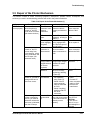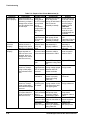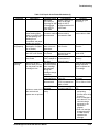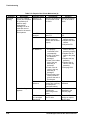
1
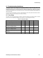
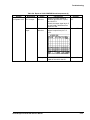
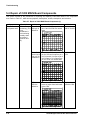
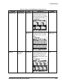
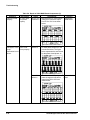
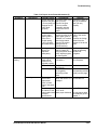
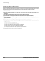
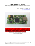
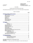
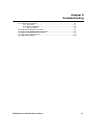
Chapter 5 Troubleshooting 5.1. Troubleshooting Guidelines ............................................................................................... 5-1 5.2.1. Error Mode........................................................................................................ 5-1 5.1.2. Sensor Checkpoints .......................................................................................... 5-3 5.1.3. Motor Checkpoints ............................................................................................ 5-3 5.2. Repair and Replacement of Unit Parts ............................................................................... 5-4 5.3. Repair of C202 PSB/PSE Board Components.................................................................. 5-12 5.4. Repair of C202 MAIN Board Components........................................................................ 5-14 5.5. Repair of the Printer Mechanism...................................................................................... 5-17 5.6. Pump Check Procedure................................................................................................... 5-22 EPSON Stylus COLOR 800 Service Manual 5-i Troubleshooting 5-ii EPSON Stylus COLOR 800 Service Manual Troubleshooting 5.1 Troubleshooting Guidelines This section describes how to identify and troubleshoot problems to repair the printer either to the unit/assembly level or to the component level. When replacing or repairing units or assemblies, follow the flowchart for that assembly or unit, which enables you to isolate the problem easily, based on the symptom. To repair to the component level, see sections 5.3 and 5.4, which provide checkpoints listed separately for major electric parts. This section provides information on the error modes displayed on the control panel and check lists used to determine if the units in each assembly are normally functioning. 5.1.1 Error Mode The LEDs on the control panel identify a number of abnormal conditions for this printer. Table 5-1 lists the printer errors and corresponding LED status. (See Figure 5-1 for the arrangement of LEDs.) Table 5-1. Printer Error Status Printer status Initial ink charge sequence is proceeding. Ink cartridge change sequence is proceeding. Paper out. Paper jam. Black ink cartridge ink end; No black ink cartridge installed. Black ink cartridge ink low. Color ink cartridge ink end; No color ink cartridge installed. Color ink cartridge ink low. Maintenance required. (Waste ink pads need replacing.) Fatal error. Note: “−−−” means no effect. EPSON Stylus COLOR 800 Service Manual LED (a) Blinks Blinks −−− −−− −−− LED (b) −−− −−− On Blinks −−− LED (c) −−− −−− −−− −−− On LED (d) −−− −−− −−− −−− −−− −−− −−− −−− −−− Blinks −−− −−− On −−− Blinks −−− Blinks −−− Blinks Blinks Blinks Blinks Blinks On On 5-1 Troubleshooting (b) (c) (d) (3) (a) (2) (4) (1) Figure 5-1. Control Panel 5-2 EPSON Stylus COLOR 800 Service Manual Troubleshooting 5.1.2 Sensor Checkpoints Table 5-2 shows the checkpoints for each sensor. Table 5-2. Checkpoints for Each Sensor Sensor CN no. Test pin no. CN6 (HP sensor) 1: 2: 3: CN7 1: (ASF HP sensor) 2: 3: CN8 (PE sensor) 1: 2: 3: CN9 1: (Black cartridge 3: detecting sensor) CN10 1: (Color cartridge 3: detecting sensor) Printhead thermistor (on color head) HP GND HPV ASF GND ASFV PE GND PEV BCO GND CCO GND Test procedure (Set meter to DC voltage.) Place the “+” lead of the meter on pin 1 and “–” lead of the meter on pin 2. Place the “+” lead of the meter on pin 1 and “–” lead of the meter on pin 2. Place the “+” lead of the meter on pin 1 and “–” lead of the meter on pin 2. Place the “+” lead of the meter on pin 1 and “–” lead of the meter on pin 3. Place the “+” lead of the meter on pin 1 and “–” lead of the meter on pin 3. Meter reading HIGH at home position (5 V). LOW at other positions (GND). LOW at home position. HIGH at other positions. LOW when paper is loaded. HIGH when no paper is loaded. LOW when cartridge is installed. HIGH when cartridge is not installed. LOW when cartridge is installed. HIGH when cartridge is not installed. 10K Ω ± 10% at 77° F (25° C) 5.1.3 Motor Checkpoints Table 5-3 shows the checkpoints for each motor. Table 5-3. Coil Resistance for Each Motor and Check Procedure Sensor CN no. Test pin no. CN11 1: ASFA (ASF/Pump motor) 2: ASF-A 3: ASFB 4: ASF-B CN12 1: CRA (CR Motor) 2: CR-A 3: CRB 4: CR-B CN13 1: PFA (PF motor) 2: PF-A 3: PFB 4: PF-B Test procedure (Set meter to Ω.) Place one lead of the meter on pin 1 and the other lead on pin 3. Place one lead of the meter on pin 2 and the other lead on pin 4. Place one lead of the meter on pin 1 and the other lead on pin 3. Place one lead of the meter on pin 2 and the other lead on pin 4. Place one lead of the meter on pin 1 and the other lead on pin 3. Place one lead of the meter on pin 2 and the other lead on pin 4. EPSON Stylus COLOR 800 Service Manual Meter reading 9.3 Ω ± 10 % at 25 °C (77 °F) /each phase 7.8 Ω ± 10 % at 25 °C (77 °F) /each phase 5 Ω ± 10 % at 25 °C (77 °F) /each phase 5-3 Troubleshooting 5.2 Repair and Replacement of Unit Parts This section contains flowcharts that let you isolate faulty units by following the flowchart for the problem. You can identify the faulty unit based on the primary symptom listed in Table 5-4. Refer to sections 5.3, 5.4, and 5.5 for information on repair to the component level for the PSB/PSE board, MAIN board, and the printer mechanism. Table 5-4. Symptoms and Corresponding Flowcharts Symptom The printer does not operate at all. CR moves abnormally. Cause No LED goes on. LED goes on but the printer mechanism does not operate at all. When the printer is powered on, the CR leaves home position and a fatal error is indicated. (The printer makes no abnormal noise.) When the printer is powered on, the CR motor immediately starts rotating irregularly and a fatal error is indicated. When the printer is powered on, the CR does not move at all. After the power on sequence, the printer attempts to eject a sheet for about 10 seconds and then indicates a paper jam error. If the LOAD button is pressed or any paper loading operation is activated after the power on sequence, the printer loads paper from the ASF and then indicates a fatal error. If the LOAD button is pressed or any paper loading operation is activated after the power on sequence, the printer indicates a fatal error. No image is printed. Faulty printing result (dot missing, uneven printing) No LEDs on the control panel go on. Buttons on the control panel do not function normally. Power on button does not work. Flowchart 1 2 The printer feeds paper abnormally. 3-1 3-2 Printing is abnormal. The control panel does not function normally. 5-4 4-1 4-2 5 EPSON Stylus COLOR 800 Service Manual Troubleshooting Flowchart 1: The printer does not operate at all. Start Check for error light indication. If the lights indicate an error, use Table 5-1 to determine the problem. If there are no lights, follow this flowchart. Is the AC voltage correct? NO Use only the correct AC voltage. YES Has fuse F1 on the PSB/PSE board blown out? YES Replace the fuse. Then disconnect CN4 on the main board and turn on power again. NO NO Is the output voltage from CN2 on the PSB/PSE board normal? Does the fuse blow again? YES NO Replace the PSB/PSE board. YES Check motors, printhead, and drivers, and if bad, replace. (See Section 5-5, Repair of the Printer Mechanism .) NO Is the problem corrected? YES End Is the problem corrected? YES NO Replace the main board. End Figure 5-2. Flowchart 1 EPSON Stylus COLOR 800 Service Manual 5-5 Troubleshooting Flowchart 2: CR moves abnormally. Start Does CR move when you turn on printer? Is the CR motor connector cable connected to CN12? NO NO Is the operation normal? Connect the CR motor connector cable to the CN12 properly. YES YES YES NO Does CR leave home position, stop, and then fatal error occurs? Do you NO hear a strange noise after printer power on, and a fatal error occurs? YES Is CR motor coil resistance OK? See Section 5.5, Repair of the Printer Mechanism. Is the HP sensor cable connected securely to CN6? YES NO NO YES Connect the HP sensor cable to CN6. NO Replace the MAIN board. NO NO Release CR lock lever with power off. YES Does PF rmotor rotate? Is the operation normal? YES Is there foreign YES matter between HP sensor terminals? See Section 5.5, Repair of the Printer Mechanism. NO YES Do PF rollers rotate with power on? NO Is the PF motor cable connected securely to CN13? NO YES End END Is the resistance of PF motor coils normal? YES Is the operation normal? Does HP NO sensor function normally? Replace the PF motor. Also check drivers and replace if bad. NO YES Replace the MAIN board. Release CR lock lever with printer power off. Does CR move smoothly manually? YES NO Replace the cap assembly or reinstall it. NO Is the operation normal? YES Replace the HP sensor. YES Is the operation normal? NO YES YES Replace the MAIN board. Is the cap assembly OK? Is the operation normal? NO NO NO Remove foreign matter. NO Reconnect the cable to CN13. YES Operate the unit several times to be sure the problem is solved. YES NO YES Is the CR lock lever released? Is the operation normal? Replace the CR motor. Check drivers and replace if bad. YES End END Is the operation normal? YES NO End END See Section 5.5, Repair of the Printer Mechanism. NO Oil the CR or clean the CR shaft. (See Chapter 6.) CAUTION: Do not use too much oil. End END Figure 5-3. Flowchart 2 5-6 EPSON Stylus COLOR 800 Service Manual Troubleshooting Flowchart 3-1: The printer feeds paper abnormally. Start After CR lock is released, does PF roller move when printer is turned on? Is the PF motor cable securely connected to CN13? NO NO Connect the cable securely to CN13. YES YES NO Is the resistance of the PF motor coil normal? YES Is the operation normal? Replace the PF motor. Check the drivers and replace if bad. NO YES Is the operation normal? YES NO Replace the MAIN board. End END After printer power on, does it keep trying to feed paper and indicate a fatal error? After printer power on, does it keep trying to eject a sheet and indicate a fatal error? NO YES If the LOAD button is pressed or printing is activated, does a fatal error occur? NO YES Foreign matter is lodged on the PF sensor in the upper paper guide assembly. NO Foreign matter is lodged on the ASF HP sensor. Continued on Figure 5-5 (A). Is the PE sensor working normally? Remove the foreign matter. Remove the foreign matter. NO NO YES YES NO Is the operation normal? YES Replace the PE sensor. YES Is the operation normal? NO NO Is the operation normal? YES YES Replace the MAIN board. End END Is the ASF HP sensor working properly? NO Replace the ASF HP sensor. YES NO Is the operation normal? YES Replace the MAIN board. End END Figure 5-4. Flowchart 3-1 EPSON Stylus COLOR 800 Service Manual 5-7 Troubleshooting Flowchart 3-2: The printer feeds paper abnormally. Continued from Figure 5-4. (A) If you press LOAD or activate printing, does a fatal error occur? No If you press LOAD or activate printing, does the printer print half a sheet of paper, and a paper empty error occurs? Yes Check that CN8 is connected. Is the operation normal? Yes Yes No Is the PE sensor functioning normally? No Replace the PE sensor. Is the operation normal? Yes No Replace the MAIN board. Yes Is the ASF/ pump motor cable securely connected to CN11? Connect the ASF/pump motor cable to CN11. No END Yes Is the ASF HP sensor cable securely connected to CN7? No No No Is the resistance Yes Replace the ASF HP sensor. No No No No Is the operation normal? Yes Replace the ASF/pump motor and check the drivers. Replace if bad. Yes Is the gear (27.2 mm) disengaged from the ASF LD shaft? Is the operation normal? No Yes of the ASF/pump motor coil normal? Yes Reconnect the ASF/HP sensor cable to CN7. Yes Is the ASF HP sensor functioning normally? Is the operation normal? Is the operation normal? Yes Replace the MAIN board. Yes Engage the gear (27.2 mm) with the ASF LD shaft. END Figure 5-5. Flowchart 3-2 5-8 EPSON Stylus COLOR 800 Service Manual Troubleshooting Flowchart 4-1: Printing operation is abnormal. Start Does the printer print after power on? No Does the printer indicate Ink End or No Cartridge error? Yes Replace the ink cartridge. Is printing normal? Yes No Have you replaced the cartridge during the ink change sequence? Yes No Yes Does the sensor properly detect the presence of a cartridge? End Print nozzle check pattern. Do all dots print OK? No No Is head FFC continuity OK? Continued in Figure 5-7 (A). Yes No Yes Most nozzles print. No No White banding problem occurs? Yes Is printing normal? Replace or clean the PF roller or gear (70 mm). Yes Replace the head unit. Is printing normal? Yes No Replace the head FFC. Is printing normal? Yes Image is not clear. Start the cartridge replacement sequence and replace the ink cartridge again. No Yes No Replace the MAIN board. Yes Is printing normal? Yes No Yes Are the head gap and Bi-d correct? No Perform Head Gap timing and Bi-d adjustments. Are the correct printer driver and paper settings selected? No Yes No Are head angle and vertical adjustments correct? No Yes Are the correct printer driver and paper settings selected? Yes Perform the Head Angle and BK-M Linear Adjustments. No No Is printing normal? Is printing normal? Use the driver for Stylus COLOR 800 or select the proper paper settings. Yes Is printing normal? Yes Repair printer mechanism. See Section 5.5. Yes Use the driver for Stylus COLOR 800 or select the proper paper setting. Is printing normal? Yes No Yes End Replace the MAIN board. Figure 5-6. Flowchart 4-1 EPSON Stylus COLOR 800 Service Manual 5-9 Troubleshooting Flowchart 4-2: Printing operation is abnormal. (A) Continued from Figure 5-6. NO Most nozzles print. YES Is the head cleaner NO properly functioning? Run cleaning cycles using the cleaning button. (See procedure in Chapter 6.) Is the printing normal? YES NO Replace the head cleaner or the pump unit. YES Does your PC have NO the correct printer driver? NO Is the printing normal? YES Is the head cleaner positioned correctly? Run self-test for 1 line. Then perform necessary cleaning, using the CLEANING button in self-test mode. YES Perform cleaning by alternating printing the nozzle check in the driver utility and running the head cleaning. (5 times, maximum.) Is the printing normal? YES NO YES Reinstall the head cleaner or replace it. NO Does NO the pump unit absorb the ink? Is the printing normal? YES Check or replace the cap unit or the the pump unit. YES NO Is the printing normal? YES NO Is the ink cartridge more than 2/5 full? YES Run the manual initial ink charge operation in the adjustment program. NO End Is the printing normal? Enter the ink cartridge change sequence to install a newly unpacked ink cartridge. YES NO Replace the defective head FFC. YES YES NO YES Is the head FCC continuity normal? End Is the printing normal? NO Is the printing normal? Replace the defective printhead. NO Replace the MAIN board. End Figure 5-7. Flowchart 4-2 5-10 EPSON Stylus COLOR 800 Service Manual Troubleshooting Flowchart 5: .The control panel does not function normally. Start Does the Power button operate normally? Switch on and off and check the continuity between each signal line for the Power button on the control panel and ground using a multimeter. NO YES Do the buttons on the control panel normally operate? NO Switch on and off, and check the continuity between each signal line for the buttons on the control panel and ground using a multimeter. NO Is the operation normal? Is the operation normal? NO Is the FFC properly connected? YES YES NO Connect the panel FFC properly. YES Is the FFC properly connected? NO YES NO Connect the panel FFC properly. NO Is the operation normal? Check NO FFC for continuity. Is there continuity? YES Is the operation normal? YES Replace the FFC. YES Check FFC for continuity. Is there continuity? NO NO Replace the FFC. Is the operation normal? YES Replace the control panel. YES NO Is the operation normal? YES Is the operation normal? NO Replace the control panel. Is the operation normal? YES Is there continuity between pin 5 of CN4 and pin 10 of CN5 on the MAIN board? YES NO Replace the MAIN board. NO YES NO Replace the MAIN board. Is the operation normal? YES Replace the PSB/PSE board. End End Figure 5-8. Flowchart 5 EPSON Stylus COLOR 800 Service Manual 5-11 Troubleshooting 5.3 Repair of C202 PSB/PSE Board Components This section describes procedures for replacing and repairing the C202 PSB/PSE board to the component level. Refer to tables 5-5 and 5-6 for symptoms, descriptions, causes, checkpoints, and solutions. Table 5-5. Repair of C202 PSB/PSE Board Components (1) System Description Cause The printer does Neither +45 V nor F1 is open. not operate at all. +5 V is output. T1 is open. Q1 is bad. Q2 is defective. Q31 is defective. 5-12 Checkpoints Check visually if F1 is normal. Solution Replace F1. Check the voltage output using a meter. Replace T1. • Check for proper resistance between Replace Q1. the source and drain at Q1 FET. • Check that the waveform shown below is output from the drain of Q1 FET. • Unplug the AC inlet; then check for proper resistance between the collector and emitter of transistor Q2. • Check that Q2 switching is correctly functioning with printer power on. • Unplug the AC inlet; then check for proper resistance between the source and drain of Q31 FET. • Check that Q31 FET switching is correctly functioning with printer power on. Replace Q2, or check if PC1 is functioning. Replace Q31, or check if PC1 is functioning. EPSON Stylus COLOR 800 Service Manual Troubleshooting Table 5-6. Repair of C202 PSB/PSE Board Components (2) System Description Cause The printer does Neither +42 V nor PC1 is not operate at all. +5 V is output. defective. +5 V is not output. IC51 is defective. Checkpoints Solution Replace the • Check for proper resistance between pins 5 and 6 or pins 7 PC1. and 8 of PC1. • Check the output signal at pin 5 to verify that it alternates from HIGH to LOW. • Check that the waveform shown Replace IC51. below is output from pin 7 of IC51. L51 is open. • Check resistance between 2 leads of the coil for the L51. EPSON Stylus COLOR 800 Service Manual Replace L51. 5-13 Troubleshooting 5.4 Repair of C202 MAIN Board Components This section consists of the procedures for replacing and repairing C202 MAIN board to the component level. Refer to Table 5-7, which shows symptoms, descriptions, causes, checkpoints, and solutions. Table 5-7. Repair of C202 MAIN Board Components (1) Symptom Description Cause Checkpoints The printer does CPU is not Reset IC for • Check that 5 V is output from not operate at all. functioning. (The IC9 logic is pins 1 and 3 of IC9 at a normal driver defective. state. mechanism is not functioning correctly when the printer is turned on and off.) Solution Replace the reset IC for IC9. Reset IC for • Check that +5 V is output from Replace IC8 or the IC8 42 V pin 6 of IC8 and is input to pin 1 IC19. line or IC19 of IC19, and 0 V is input to pin 2 is defective. of IC19 and +5 V is output from pin 4 of IC19 in a normal state. CRU1 or CRU2 is defective. 5-14 • Check that the waveform shown below is output from both leads of the CRU. Replace the defective CRU. EPSON Stylus COLOR 800 Service Manual Troubleshooting Table 5-8. Repair of C202 MAIN Board Components (2) Symptom CR does not operate properly. Paper is not fed properly. Description Cause Checkpoints Solution CR does not IC13 or IC2 • Check that the driving waveform Replace IC13. operate properly. is defective. for each phase output from IC13 is as shown below. The figure below represents the waveforms for the phase A and phase –A. PF motor does not operate properly. IC1 or IC2 is • Check that the CR motor phase defective. changeover waveform output from IC2 to IC13 is as shown below. Replace the MAIN board. IC16 or IC2 • Check that the drive waveform is defective. for each phase output from the IC16 is as shown below. The figure below represents the waveforms for the phase A and phase –A. Replace the IC16. EPSON Stylus COLOR 800 Service Manual 5-15 Troubleshooting Table 5-9. Repair of C202 MAIN Board Components (3) Symptom Paper is not fed properly. Description PF motor does not operate properly. ASF does not ASF / pump load paper, or the motor is not pump driven properly. mechanism is not driven. Cause Checkpoints IC16 or IC2 • Check that the PF motor phase is defective. changeover waveform output from IC2 to IC16 is as shown below. Solution Replace the MAIN board. Replace IC6. IC6 or IC2 is • Check that the drive waveform defective. for each phase output from IC6 is as shown below. The figure below represents the waveforms for the phase A and phase –A. IC1 or IC2 is • Check that the ASF/pump motor Replace MAIN defective. board. phase changeover waveform output from IC2 to IC6 is as shown below. 5-16 EPSON Stylus COLOR 800 Service Manual Troubleshooting 5.5 Repair of the Printer Mechanism This section consists of tables containing symptoms, descriptions, possible causes, checkpoints, and solutions you need in troubleshooting problems with units in the printer mechanism. Table 5-10. Repair of the Printer Mechanism (1) Symptom CR does not move properly. Description A fatal error occurs when the printer is turned on, and CR motor does not rotate. (No abnormal noise.) When the printer is turned on, the CR moves away from home position, a fatal error is indicated, and the CR stops. (No abnormal noise.) Possible cause The CR motor connector is not properly connected. Checkpoints Solution Check if the CR motor Connect the CR connector cable is motor connector properly connected to cable to CN12. CN12. CR motor coil is Check CR motor coil open. resistance, referring to Table 5-3. The timing belt Check if the timing is not engaging belt is engaged with the gears. the CR pinion gear of the belt pulley. HP sensor Check if the HP connector is sensor connector disconnected. cable is connected to CN6. Dirt or other foreign matter is lodged between HP sensor terminals. HP sensor is defective. Reinstall the timing belt or replace it. Connect the HP sensor connector cable to the CN6. Check if there is dirt or Remove foreign foreign matter lodged substance. between HP sensor terminals. Check if the HP sensor is correctly functioning, referring to Table 5-2. When the printer is CR lock lever is 1. Check PF motor turned on, you hear a not released. coil resistance, strange noise and a using Table 5-3. fatal error occurs. 2. Check if the PF motor connector cable is connected to CN13. 3. Check if anything interferes with CR lock lever movement. When turning on the Oil in the CR oil Release the CR lock printer or activating pad has dried lever with printer power the CR, you hear an up. off and check if the CR abnormal noise and a manually moves fatal error is indicated; smoothly. then the CR stops. EPSON Stylus COLOR 800 Service Manual Replace the CR motor. Replace HP sensor. 1. Replace PF motor. 2. Connect PF motor connector cable to CN13. 3. Remove the interference. Oil the oil pad built in the CR unit. CAUTION: Do not use too much oil, or you could damage the printhead. 5-17 Troubleshooting Table 5-11. Repair of the Printer Mechanism (2) Symptom CR does not move properly. Solution Oil the sliding part of the CR unit and the top frame, or remove foreign matter, if found. CAUTION: Do not use too much oil, or you could damage the printhead. Foreign matter Release CR lock lever Replace the CR oil lodged between with power off and pad. CR shaft and check if CR moves Clean the CR shaft CR unit. smoothly manually. using a soft cloth. The CR does CR returns to home Cap in cap Check whether the Reinstall the cap not move position, there is a assembly does cap assembly is assembly or properly. strange noise, and a not fit cap properly installed. replace the cap fatal error is indicated. frame. assembly. Paper is not fed PF motor does not PF motor Check if the PF motor Connect the PF properly. rotate at power on. connector cable connector cable is motor connector (CR lock lever is not is disconnected. connected to CN13. cable to CN13. released, there is a strange noise, and a fatal error occurs.) PF motor coil is Check PF motor coil Replace PF motor. open. resistance using Table 5-3. When the printer is Foreign matter Check if there is Remove the turned on, it keeps lodged between foreign matter lodged foreign matter. trying to load paper, ASF HP sensor between ASF HP and indicates a fatal terminals. sensor terminals. error. ASF HP sensor Check if the ASF HP Replace the ASF is defective. sensor is properly HP sensor. functioning using Table 5-2. When the printer is Foreign matter Check if there is Remove the turned on, it keeps is blocking the foreign matter on the foreign substance. trying to load paper; PE sensor. PE sensor lever and then indicates a paper rear paper guide. jam error. If you press LOAD or ASF/pump Check if the Connect ASF/ try to print when the motor connector ASF/pump motor pump motor printer is turned on, a cable is connector cable is connector cable to fatal error occurs. disconnected. connected to CN11. CN11. ASF HP sensor Check ASF HP sensor Connect ASF HP connector cable cable is connection to sensor connector is disconnected. CN7. cable to CN7. ASF/pump Check ASF/pump Replace the motor coil open. motor coil resistance ASF/pump motor. using Table 5-3. 5-18 Description When the printer is turned on or the CR is activated, you hear a strange noise; a fatal error is indicated; then the CR stops. Possible Cause Either the sliding part of the CR unit and the top frame are not lubricated or foreign matter is jamming the CR. Checkpoints Release the CR lock lever with printer power off and check if the CR moves smoothly manually. EPSON Stylus COLOR 800 Service Manual Troubleshooting Table 5-12. Repair of the Printer Mechanism (3) Symptom Paper is not fed properly. Description Possible cause Black gear (27.2 mm) on right edge of ASF is disengaged from ASF LD roller shaft After power on, printer PE sensor starts loading paper connector cable is when you press LOAD disconnected. or start printing, but loading is not completed, and paper empty error occurs. ASF keeps trying to ASF LD roller is load paper, but paper worn or there is is not loaded. paper dust. Last sheet of paper in The guide sheet is the ASF is not loaded. not placed. Transparency sheets not loaded. Abnormal printing Ink out or ink end occurs when you turn on the printer, but the cartridge is new. Transparency (OHP) adapter is not used. Ink consumption counter not reset when cartridge was replaced during ink cartridge change sequence. Ink cartridge sensor defective. Head FFC is disconnected. Head FFC is damaged. All dots or most dots in Bubbles in the the nozzle check cavity. pattern are not printed. EPSON Stylus COLOR 800 Service Manual Checkpoints Check if gear (27.2 mm) on the right edge of ASF is engaged with the LD roller shaft. Solution Reinstall the gear (27.2 mm). Check if the PE sensor cable is connected to CN8. Connect the PE sensor cable to CN8. Check the surface of the LD roller. Clean or replace the LD roller. Check if the appropriate guide sheet is used. Check if the adapter is mounted or is correctly used. Use the appropriate guide sheet. Use the OHP adapter correctly. Enter the ink cartridge change sequence again to replace the ink cartridge. Check sensor, using Table 5-2. Check if the head FFC is connected to CN9 or CN10. Check current of pin 1 for each head FFC. Replace the printhead. Connect the correct FFC to CN9 or CN10. Replace the head FFC. 1. Alternate cleaning and printing. (Printer driver utility is useful.) 2. If ink in cartridge is more than 2/5, run initial ink charge sequence in the adjustment program. 3. Enter ink cartridge change sequence to install a newly unpacked ink cartridge. 5-19 Troubleshooting Table 5-13. Repair of the Printer Mechanism (4) Symptom Abnormal printing Description You run 5 cleaning cycles (see Chapter 6 for procedure) or install a newly unpacked ink cartridge, but all or most dots are not printed in the nozzle check pattern. Possible cause Head FFC is disconnected. Head FFC is damaged. Pump unit does not absorb ink. Printhead is defective. White banding appears. Dot missing PF roller is worn or is smudged with the ink. 5-20 Checkpoints Solution Check if the head FFC Connect the correct is connected to CN9 FFC to the CN9 or or CN10. CN10. Check the continuity of each FFC. Check if the head cleaner comes into contact with the head properly. 1. Check if ink tubes are properly connected to the cap assembly. 2. Check if ink tubes are twisted or damaged. 3. Check if the rubber part of the cap assembly is deformed. 4. Check if the air valve in the cap assembly is damaged. 5. Perform the pump check procedure given at the end of this chapter. (If the problem still occurs after verifying all checkpoints mentioned above.) Check the nozzle condition by performing nozzle check. Check the surface of the PF roller. Replace the head FFC. 1. Adjust the head cleaner position. 2. Replace the head cleaner. 3. Adjust the PG. 1. Connect the ink tubes to the cap assembly properly. 2. Replace the ink tubes or the pump unit. 3. Replace the cap assembly. 4. Replace the air valve or the cap assembly. 5. See page 5-22. Replace the printhead. Refer to the solution described in the previous page. Clean the PF roller surface or replace the PF roller. EPSON Stylus COLOR 800 Service Manual Troubleshooting Table 5-14. Repair of the Printer Mechanism (5) Symptom Description Image is not clear. Abnormal printing Image is not clear. Ink smudges. Possible cause Some gear teeth broke or the gear (70 mm) does not engage the PF roller shaft properly. Checkpoints Check the teeth of the gear (70 mm). Check if the gear (70 mm) rotates constantly with the torque from the PF motor. The driven roller Check if the surface of on the upper the driven roller on the paper guide is upper paper guide is worn or the blackish or is covered torsion spring with foreign matter. (117.6 g) lacks Check if the torsion sufficient tension. spring is bent or hooked securely. Head gap or Check the head gap Bi-d is not and Bi-d status by adjusted using the printer driver adequately. utility, adjust program, or control panel. Head angular or Refer to 4-12 and 4-15 head vertical in Chapter 4. position is not adjusted properly. PG is too wide. Check the position of the PG lever. Dot missing Check if the nozzles are clogged by performing nozzle check. There is ink on the Feed a sheet of plain driven roller, paper, and check if it is upper paper smudged. guide, or other parts of the paper path The platen gap is Check the position of too narrow, or the the PF lever. paper loaded does Check paper thickness. not meet specifications. EPSON Stylus COLOR 800 Service Manual Solution Replace the gear (70 mm) or reinstall the gear (70 mm) properly. Replace the driven roller or the torsion spring. Remove the foreign matter from the surface of the driven roller. Perform adjustment using the adjusting utilities and programs. Refer to 4-12 and 415 in Chapter 4. Set the lever to “0”. Refer to the corresponding solution on the previous page. Clean the part covered with ink. Set the PG lever to “+.” Use only paper within specifications given in Chapter 1. 5-21 Troubleshooting 5.6 Pump Check Procedure When you encounter missing dots in the printout, and you have run cleaning cycles and the initial ink charge sequence without success, try the following procedure to check the pump and clear the nozzles: 1. Turn the printer off. 2. Move the printhead manually to the right until you hear the click that means the carriage lock is disengaged. 3. Then slide the carriage assembly left enough to see the capping mechanism. 4. Using a dropper (or straw) place several drops of warm water into the capping mechanism. 5. Turn the printer back on. The carriage moves back to the home position, and the printhead is above capping mechanism. 6. Follow the procedure in Chapter 3, Disassembly to remove the printer mechanism. 7. Turn the printer on and see if water flows through the tubes to the waste ink pads. If water does not flow through the tubes: Check for twisted or damaged tubes. Check if ink tubes are properly connected. Check if the rubber part of the cap assembly is damaged. Check if the air valve in the cap assembly is damaged. If everything with the tubes is OK, replace the pump mechanism. 8. Reassemble the printer and run another cleaning cycle. 5-22 EPSON Stylus COLOR 800 Service Manual