1
REMOTE DATA TRANSMISION SYSTEM
A Major Qualifying Project:
submitted to the Faculty
of the
WORCESTER POLYTECHNIC INSTITUTE
and performed at SRI INTERNATIONAL
in partial fulfillment of the requirements for the
Degree of Bachelor of Science
by
____________________________
Eric Hall
____________________________
Peter Kaineg
____________________________
Amanda Quigley
____________________________
Eric Young
Date: March 4, 2006
Approved:
______________________________
Professor John Orr, Major Advisor
Advisors:
Roy Stehle
Todd Valentic
Andrew Young
Table of Contents
Abstract ............................................................................................................................ viii
Executive Summary........................................................................................................... ix
1
Introduction................................................................................................................. 1
2
Background ................................................................................................................. 2
2.1
Scientific Background......................................................................................... 2
2.1.2
Why Transmit Data in Real Time? ............................................................. 2
2.1.3
Why Deploy Arctic Sensing Systems? ....................................................... 2
2.1.4
Existing Systems for Real Time Data Transmission .................................. 3
2.1.5
A New Approach to Remote Data Transmission........................................ 4
2.2
Alaskan Weather................................................................................................. 5
2.3
Collecting Data ................................................................................................... 8
2.3.2
System Description ..................................................................................... 9
2.3.3
Peripherals................................................................................................... 9
2.3.4
Software .................................................................................................... 10
2.3.5
Short Cut (SCWin).................................................................................... 10
2.3.6
CRBasic .................................................................................................... 11
2.4
Sending Data..................................................................................................... 11
2.4.2
Iridium Satellite Data Network................................................................. 12
2.4.3
Data Transport Network ........................................................................... 13
2.4.4
Python Programming Language ............................................................... 14
2.5
Power System.................................................................................................... 15
2.5.2
Battery....................................................................................................... 15
2.5.3
Power Generation...................................................................................... 16
2.5.4
Charge Controller...................................................................................... 18
3
Specifications............................................................................................................ 19
3.1
Communication Specifications ......................................................................... 19
3.2
Power Specifications......................................................................................... 19
3.3
Physical Specifications ..................................................................................... 20
4
Design Choices ......................................................................................................... 21
4.1
Quantity of Data & Frequency of Data Transmission ...................................... 21
4.2
Short Burst Data vs. Dial Up ............................................................................ 23
4.2.2.1 Short Burst Data Service........................................................................... 23
4.2.2.2 Dial-Up Service ........................................................................................ 24
4.3
Processing ......................................................................................................... 26
4.4
Data Transfer .................................................................................................... 27
5
Design Documentation.............................................................................................. 29
5.1
Power System.................................................................................................... 29
5.1.2
Battery....................................................................................................... 30
5.1.3
Solar Panel ................................................................................................ 30
5.1.4
Charge Controller...................................................................................... 30
5.2
Switching Circuit .............................................................................................. 31
5.2.2
High level Design ..................................................................................... 31
ii
5.2.3
Circuit Operation ...................................................................................... 33
5.2.4
Part Selection ............................................................................................ 33
5.2.5
Control Port............................................................................................... 33
5.2.6
Assembly................................................................................................... 34
5.3
CR1000 Code.................................................................................................... 34
5.3.2
Top Level System ..................................................................................... 34
5.3.3
Transmit Data............................................................................................ 36
5.3.4
Establish Connection ................................................................................ 37
5.3.5
Data Out .................................................................................................... 39
5.3.6
Accept New Transmit Period.................................................................... 42
5.4
Data Management Code.................................................................................... 43
5.4.2
Receiving the Data.................................................................................... 44
5.4.3
Preparing Data for Viewing ...................................................................... 49
5.4.4
Website ..................................................................................................... 54
6
Testing and Results ................................................................................................... 59
6.1
CR1000 Code Tests .......................................................................................... 59
6.1.2
Hello World .............................................................................................. 59
6.1.3
Serial In..................................................................................................... 60
6.1.4
Data Collection ......................................................................................... 62
6.1.5
Send Data .................................................................................................. 63
6.1.6
Control Port Time ..................................................................................... 65
6.1.7
Iridium Hello World ................................................................................. 67
6.2
Python Code Tests ............................................................................................ 68
6.2.2
Computer to Computer ............................................................................. 68
6.3
Full System Tests.............................................................................................. 69
6.3.2
Reliability & Frequency............................................................................ 69
6.3.3
NO CARRIER .......................................................................................... 70
6.3.4
Data Transfer Rate .................................................................................... 71
6.3.5
Full System Reliability ............................................................................. 73
6.4
Energy Testing .................................................................................................. 74
6.4.2
Communications Energy Consumption .................................................... 74
6.4.3
Datalogger Energy Consumption.............................................................. 76
6.4.4
Battery State of Charge Expectation......................................................... 78
7
Recommendations for Future Work.......................................................................... 82
7.1
Universal Datalogger Communications............................................................ 82
7.2
Dial up and SBD communications.................................................................... 82
7.3
Mobile Terminated Calling............................................................................... 83
7.4
Camera for Datalogger...................................................................................... 83
7.5
ISU-to-PSTN Communications ........................................................................ 83
8
Conclusion ................................................................................................................ 84
Appendix A – CR1000 Code ............................................................................................ 85
Appendix B – Data Managment Code .............................................................................. 92
Reading ......................................................................................................................... 92
Datalogger..................................................................................................................... 95
Receive........................................................................................................................ 103
Store ............................................................................................................................ 105
iii
plotGenerator .............................................................................................................. 110
System Requirements.................................................................................................. 115
Appendix C – User’s Manual ......................................................................................... 116
Physical Setup............................................................................................................. 116
Datalogger Connections.............................................................................................. 117
CSI Voltage Divider ................................................................................................... 119
Mounting Panel Connections...................................................................................... 119
PV panel and Antenna ................................................................................................ 121
Batteries ...................................................................................................................... 121
CR1000 Code User Manual ........................................................................................ 122
References....................................................................................................................... 127
iv
Table of Figures
Figure 1: NOAA/PMEL Webcam shot.............................................................................. 3
Figure 2: GEOSummit webpage (www.geosummit.org) ................................................... 4
Figure 3: Location of Kotzebue .......................................................................................... 5
Figure 4: Average and Extreme Temperatures for Kotzebue, AK ..................................... 5
Figure 5: Average Monthly Precipitation in Kotzebue, AK ............................................... 6
Figure 6: Cloudiness in Kotzebue, AK ............................................................................... 6
Figure 7: Insolation in Kotzebue, AK................................................................................. 7
Figure 8: Wind Speeds in Kotzebue, AK............................................................................ 7
Figure 9: Standard components of a CSI Datalogger ......................................................... 8
Figure 10: CR1000 Datalogger........................................................................................... 9
Figure 11: A CR1000 used in a weather station ................................................................ 9
Figure 12: Screen shot of SCWin ..................................................................................... 11
Figure 13: Iridium Satellites cover the Earth.................................................................... 12
Figure 14: Iridium coverage.............................................................................................. 13
Figure 15: Message Queue at Local Iridium Connection ................................................. 14
Figure 16: Publishing and Subscribing to Data from Central Newsgroup Server............ 14
Figure 17: Temperature Effect on Battery Capacitance ................................................... 16
Figure 18: Estimated Solar Power Output ........................................................................ 17
Figure 19: Three Stages of Charging L-A Battery............................................................ 18
Figure 20: Physical setup of the System ........................................................................... 20
Figure 21: Basic architecture of the Iridium SBD ............................................................ 23
Figure 22: Costs of SBD v. Dial-up.................................................................................. 24
Figure 23: ISU-to-PSTN overview ................................................................................... 25
Figure 24: ISU-to-ISU overview ...................................................................................... 25
Figure 25: Subsystems ...................................................................................................... 29
Figure 26: Power System Block Diagram ........................................................................ 29
Figure 27: Charging Two Batteries with Single PV ......................................................... 31
Figure 28: CSI sample switching circuit........................................................................... 32
Figure 29: Switching Circuit Schematic ........................................................................... 32
Figure 30: Assembled Circuit Box ................................................................................... 34
Figure 31: System Flowchart – Top Level ....................................................................... 35
Figure 32: Transmit Data Flowchart................................................................................. 37
Figure 33: Establish Connection Flowchart...................................................................... 39
Figure 34: Data Out Flowchart ......................................................................................... 41
Figure 35: New Transmit Period Flowchart ..................................................................... 43
Figure 36: Basic Overview of the End System Code ....................................................... 44
Figure 37: Overview of Receive ....................................................................................... 45
Figure 38: Overview of Datalogger .................................................................................. 45
Figure 39: Overview of the ‘receive’ function ................................................................. 47
Figure 40: Overview of the ‘isNoCarrier’ function .......................................................... 48
Figure 41: Overview of the ‘retrieveData’ function ......................................................... 49
Figure 42: Overview of Store ........................................................................................... 50
Figure 43: Overview of ‘storeReadings’........................................................................... 51
Figure 44: Overview of plotGenerator.............................................................................. 53
Figure 45: Website Sidebar............................................................................................... 55
v
Figure 46: Website’s System Health Check ..................................................................... 56
Figure 47: Website’s Query page ..................................................................................... 57
Figure 48: Website’s Database View................................................................................ 58
Figure 49: Hello World Program ...................................................................................... 59
Figure 50: Hyper-Terminal “Hello World” ...................................................................... 60
Figure 51: Timing control ports program ......................................................................... 61
Figure 52: Data Collection Program ................................................................................. 63
Figure 53: Send Out Data Program................................................................................... 64
Figure 54: Hyper-Terminal CR1000 Data Point............................................................... 65
Figure 55: Timing control ports program ......................................................................... 66
Figure 56: Iridium Hello World Program ......................................................................... 68
Figure 57: Current Profile (Connect First Attempt) ......................................................... 75
Figure 58: Current Profile (Connect Second Attempt) ..................................................... 75
Figure 59: Current Profile (Connect Third Attempt)........................................................ 76
Figure 60: Current Drawn when taking Measurements.................................................... 77
Figure 61: Transmission Mode Current Profile ................................................................ 78
Figure 62: Effect of temperature on Battery Capacity in Kotzebue, AK.......................... 79
Figure 63: Expected Energy Output for Each day of the Year ......................................... 80
Figure 64: Iridium Battery State of Charge ...................................................................... 81
Figure 65: Datalogger Battery State of Charge................................................................. 81
Figure 66: Full sensing station........................................................................................ 117
Figure 67: Datalogger enclosure..................................................................................... 117
Figure 68: Datalogger with all connections necessary for communications .................. 118
Figure 69: VDIV10:1 (voltage divider for reading greater than 5V).............................. 119
Figure 70: Mounting panel connections ......................................................................... 120
Figure 71: Mounting Panel Schematic............................................................................ 121
Figure 72: Deka 8G31 12V 100Ah gel cell battery ........................................................ 122
Figure 73: Header Information ....................................................................................... 123
Figure 74: Scan/Store Intervals Example ....................................................................... 124
Figure 75: Read_Sensors Subroutine.............................................................................. 125
Figure 76: Data Table Declaration.................................................................................. 125
vi
Table of Tables
Table 1: Comparing the Amount/Frequency of Data to Send .......................................... 21
Table 2: Cost per year ....................................................................................................... 21
Table 3: Energy consumed per year.................................................................................. 22
Table 4: External Microcontroller vs. CR1000 Internal Microcontroller......................... 26
Table 5: Data Transfer Mobile Originated vs. Mobile Terminated Weighted Chart........ 27
Table 6: Overnight Frequency & Reliability Test ............................................................ 70
Table 7: Weekend data rate test ........................................................................................ 73
Table 8: Energy Consumption of System ........................................................................ 78
vii
Abstract
The primary goal for this project was to create an autonomous remote data transmission
system for environmental researchers collecting data in remote locations. The system will
be used in Kotzebue, AK to monitor environmental conditions. To design this system an
interface between the Iridium Satellite Network and Campbell CR1000 datalogger was
implemented and analyzed. The solution includes a fully functional prototype which is
able to provide near real-time access to collected data.
viii
Executive Summary
The Center for GeoSpace Studies at SRI conducts research relating to the upper
atmosphere and space environment. This research often entails experiments using
incoherent scatter radar, satellite communications and optical instrumentation. The
Center is also one of the entities that make up VECO Polar Resources (VPR), the
National Science Foundation's Arctic logistics contractor. VPR supports research stations
in Alaska, Canada, Greenland, Iceland, Norway, Russia, and the Arctic Ocean.
Throughout these regions over 100 grants and 500 scientists are supported year-round for
a total of 55 different field locations. SRI’s role in VPR is to provide communications
services for VPR’s field research projects, including the deployment of data collection
and field communications systems.
SRI and VPR have received increasing requests from scientists for real-time access to
data from their research stations in remote locations. These are often small stations
collecting data from a few sensors and storing samples into a datalogger. In the past, the
data was retrieved only when the scientist visited the site, which could be as infrequent as
once a year. Several scientists explained that their system was working great while they
were there, but upon their return a year later they found that it failed shortly after leaving.
With real-time access to the data, they not only have constant monitoring capabilities, but
they can also determine if the system is functioning properly.1
This report provides design documentation as well as user and maintenance manuals for
future use and upkeep of the system. The major specifications for this project are: the
system must be able to sustain itself year round without maintenance in -40°C with ice
and snow; the system must collect and send meteorological data at least once per week
over the Iridium satellite network, and the system communications costs must be under
$2400 per year. The project is divided into two systems which will communicate with
one another, a “remote end” and a “local end”. The remote end, located in Kotzebue
Alaska, will collect data periodically and send it to the local end, at SRI in Menlo Park
CA. The local end will receive the data, format it, and send it to the data transport
network, which will update a webpage displaying meteorological conditions at the remote
site.
The remote end can be broken down into three systems, data collection, communication,
and power. The data collection system consists of a multitude of sensors attached to a
Campbell Scientific Institute (CSI) datalogger through CSI multiplexers. The datalogger
was programmed to collect data from the array of sensors and transmit it at user
adjustable intervals. The datalogger will also send a system health update with each data
transmission. The communications system includes an L-Band (390MHz-1.55GHz)
Iridium modem and transmitting antenna. The power system is comprised of three major
components: a photovoltaic panel, a charge controller, and two 100Ah gel cell batteries.
The solar panel converts the available sunlight into power which is stored in the battery
via the charge controller, increasing the efficiency of the charging system. This testing
station will collect soil moisture and soil temperature readings, and transmit the data over
satellite communications to be received by the local end. The local end will include
ix
another L-Band Iridium modem and a dedicated PC running a program to receive and
format the transmitted data. The local end program which was created using the Python
programming language will send updates to the Data Transport Network which will load
the most current data onto the website.
The datalogger and the Iridium modem were both specified by and provided by SRI. The
datalogger was chosen for its high level interface to the processing and data controls. The
Iridium modem was chosen for its versatility of communications modes including
standard dial up and short burst data as well as its ability to communicate in Polar
Regions. After thorough testing and the completion of the project, the system was
shipped to Kozebue, Alaska where it was deployed. A user manual and a maintenance
manual were also provided to the researcher leading the project. The system successfully
demonstrated the functionality of this design through extensive testing. The
communications system has been thoroughly tested, also the ability to adjust the
transmission period has been implemented, and the data has been displayed on a website
for easy access. This report documents background information related to the project,
major design decisions, tests performed, and recommendations for future work.
x
1
Introduction
The National Science Foundation (NSF) was created in 1950 by Congress to promote the
progress of science and national prosperity. Today, NSF is continuing to keep the
United States at the leading edge of discoveries from astronomy to geology to zoology.
With an annual budget of $5.5 million, NSF is responsible for 20% of federally supported
research at America’s colleges and universities.
Research in the Polar Regions of the Earth is of particular importance in these times of
climate change and global warming. In order to support scientists in the Polar Regions
NSF contracts VECO Polar Resources (VPR) for all Arctic Logistics. VPR supports 500
scientists working in 55 different field locations around the Poles. The GeoSpace Center
at SRI International supplies field communications services to VPR-funded projects. The
WPI team worked at SRI to provide communications support to Dr. Patrick Sullivan’s
study of the constraints on the physiology and growth of trees at the latitude tree line.
As communications technology pushes forward, so does the demand for immediate
access to data from sensors in remote locations around the world. The resources
expended to send a researcher to one of these remote locations to manually retrieve data
is both uneconomical and impractical given today’s ability to communicate
autonomously. Real-time data coming from these remote systems would allow
researchers to monitor operating status, and keep up to date records, while saving time
and money.
The primary goal of this Major Qualifying Project was to design a general system that
can provide real-time access to scientific instruments located in remote regions of the
world. To implement the system the WPI team provided a comprehensive interface
between a Campbell Scientific Datalogger and an Iridium Satellite Transceiver.
Additionally, the team employed the Data Transfer Network, created by SRI, to make this
information available to researchers. To interface with the Data Transport Network, the
team used Python programs to process and distribute the data transmitted across the
Iridium Network.
1
2
Background
This section provides background information on all relevant aspects of the project: data
collection, data transmission, system power, and weather conditions
2.1
Scientific Background
In order to gain a greater appreciation for the impact this project will have on SRI, VECO
Polar Resources (VPR), and the scientific community at large, several topics must be
understood. In the following section the significance of polar research and real time data
transmission will be explained. Furthermore, a short overview of previous arctic remote
sensing deployments will be discussed. This section concludes by outlining theories
behind this project and how they will improve future remote sensing missions.
2.1.2 Why Transmit Data in Real Time?
SRI has received increasing requests from researchers for near real-time access to data
from their instruments in remote locations. These are often small stations collecting data
from a few sensors and storing samples into a datalogger. In the past, the data was
retrieved only when the scientist visited the site, which could be as infrequent as once a
year. Several scientists have explained that their system was working great while they
were there, but upon their return a year later they found that it failed shortly after they
left. With real-time access to the data, they not only have constant monitoring
capabilities, but can also determine if the system is functioning properly.
2.1.3 Why Deploy Arctic Sensing Systems?
Scientists and researchers are placing increasing importance on understanding
environmental effects of changes in temperature, moisture and other shifting climate
conditions. This project will be used specifically to support a research station which will
gather information about soil moisture and temperature and the effect of the growth and
regression of the latitudinal tree line over time. Dr. Patrick Sullivan is a researcher
supported by a NSF grant and being assisted by VPR. Dr. Sullivan has hypothesized that
the careful study of changes in soil moistures, temperature, and tree line over time, can
lead to conclusions about the widespread effects of global warming.
Evidence implies that temperature has significant control over the latitudinal tree line
position. Traditionally it has been viewed that rising temperatures are associated with
increases in growth of tree line trees, and the invasion of forests into tundra land.
However, numerous recent studies have observed negative growth trends in the late 20th
century among arctic and alpine tree lines studied. The most significant tree line
regressions have been noted in particularly dry areas. Clearly, there are changes
occurring in the earth’s climate, studying areas affected by these changes can provide
insight into the broader implications of phenomena such as global warming.
2
2.1.4 Existing Systems for Real Time Data Transmission
As previously stated, recent years have seen an increase in researchers need for real-time
status reports from their remote systems. As a result several organizations have begun
using satellite network technology to transmit status reports, instrument data, and even
digital images. This section will briefly overview a few such deployments.
One notable deployment took place in September of 2005. Since April of 2002 The
National Oceanic & Atmospheric Administration in conjunction with the Pacific Marine
Environmental Laboratory (NOAA/PMEL) has been deploying web cams to view the
North Pole in the summer warmth and daylight. They are set up from April to October
and redeployed each spring. The images from the cameras track North Pole snow cover,
weather conditions, as well as the status of PMELS North Pole instrumentation. This
includes meteorological and ice sensors seen in Figure 1. Among the sensors are
downward looking sounders, ice thickness poles, and camera images, which are relayed
via the Iridium satellite system. While the WPI team’s system did not employ a webcam
it did implement the Iridium satellite network to transmit data in real time. Being able to
review previous applications of Iridium’s technology was useful in the design of this
project.
Figure 1: NOAA/PMEL Webcam shot2
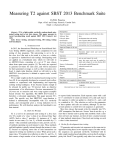
Another similar project is called the Summit Station. It is located at the peak of the
Greenland Ice Cap, and like the WPI/Sullivan project, Summit is also sponsored by the
3
NSF through VECO Polar Resources. Summit Station is home to the Greenland
Environmental Observatory, also known as GEOSummit, which provides real time
monitoring of climate conditions. This station is positioned on 3200m of ice which is
almost 400km from the nearest point of land. GEOSummit supports a diversity of
scientific research, including year-round measurements of air-snow interactions that
provide crucial knowledge for interpreting data from deep ice cores drilled both at
GEOSummit and elsewhere.
Figure 2: GEOSummit webpage (www.geosummit.org)
Figure 2, shows a screen shot of the website relating data from GEOSummit in real time.
The table in the upper left corner presents current conditions at the Summit station. In
the center of the page there are graphs continually updated displaying outside
temperature, wind speed, and wind direction. Another interesting feature is the live
webcam view which is shown on the left of the page. For Paddy Sullivan’s research
project the WPI team will create a website similar to this one, continually updating the
page with meteorological data from Paddy’s remote station in Alaska.
2.1.5 A New Approach to Remote Data Transmission
As seen above, VECO Polar Resources has had a fair amount of experience with remote
data transmission systems. However, the Sullivan project will be their first experience
interfacing a Campbell Scientific datalogger with an Iridium modem for remote
transmission purposes. While the collection of soil temperature and moisture data will be
4
of great interest to the scientific community, this project will have broader implications as
well. It will serve as a prototype system for future VPR deployments of CSI dataloggers
using the Iridium network to transmit data in real time.
2.2
Alaskan Weather
The implementation of the data logging system will be in Kotzebue, Alaska for treeline
research. Kotzebue is located on the northwest coast of Alaska, just above the Arctic
Circle (67° 28’N, 162° 14’W).
Figure 3: Location of Kotzebue3
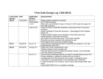
Harsh weather conditions can be expected in Kotzebue. The maximum recorded
temperature is 85°F in June of 1991 and the minimum recorded temperature is -52°F in
February, 1968. The average and extreme daily temperatures can be seen in Figure 4.
Figure 4: Average and Extreme Temperatures for Kotzebue, AK4
Due to the high latitude, the daylight hours in Kotzebue vary greatly from summer to
winter. On the winter solstice, December 21, the sun is only up for about 1.5 hours,
5
rising at 1:01PM and setting at 2:41PM. During the summer solstice Kotzebue
experiences 24 hours of sunlight. In fact, the sun rises on June 12 and sets July 2,
providing a month of uninterrupted daylight.5
Kotzebue receives 8.98in of precipitation annually on average, significantly less than
most areas in the United States. Most of this precipitation comes from July to October, as
seen in Figure 5.
Figure 5: Average Monthly Precipitation in Kotzebue, AK
When harnessing energy from the sun it is also important to take cloudiness into account.
A cloudy day can greatly impact the output of a solar panel. Figure 6 shows the monthly
averages for clear, partly cloudy and cloudy days in Kotzebue.
Cloudiness in Kotzebue, AK
25
20
15
Days
Clear
Partly Cloudy
Cloudy
10
5
0
Jan
Feb
Mar
Apr
May
Jun
Jul
Aug
Sep
Oct
Nov
Dec
Month
Figure 6: Cloudiness in Kotzebue, AK6
6
Solar energy also depends upon the strength of the sun. Solar insolation is the amount of
incoming solar radiation that reaches the planet, measured in Watts per m2. Figure 7
shows the average insolation values throughout the year measured at the top of the
atmosphere for the latitude and longitude of Kotzebue.
Solar Insolation at Kotzebue, AK
600
500
Watts per M
2
400
300
200
100
12/1/2005
11/1/2005
10/1/2005
9/1/2005
8/1/2005
7/1/2005
6/1/2005
5/1/2005
4/1/2005
3/1/2005
2/1/2005
1/1/2005
0
Day
Figure 7: Insolation in Kotzebue, AK7
The insolation values drop extremely low in the low angle sun of the winter but peak
close to 500 W/m2 in the summer, roughly half of what is received at the equator.
Another important weather condition for energy generation is wind speed. Figure 8
shows average wind speeds to be around 11mph with gusts ranging from 30mph to
48mph. In the winter the prevailing wind direction is from the East, while in the summer
the wind mostly comes from the West.
Figure 8: Wind Speeds in Kotzebue, AK
7
2.3
Collecting Data
SRI has considerable experience in remote sensing applications. Through prior efforts
they have concluded that using a single datalogger, with multiple inputs as well as
integrated memory and processor, is the most efficient way to implement data collection.
Given this knowledge, researchers at SRI have elected to employ a Campbell Scientific
Institute (CSI) datalogger to collect environmental information.
Figure 9: Standard components of a CSI Datalogger8
CSI dataloggers have been used in a variety of applications including meteorology,
agriculture, air quality, soil moisture, HVAC systems, water resources, and geological
research. These dataloggers are used all over the world to provide accurate and reliable
measurement and to control system performance. CSI has intended these systems to
execute one-time data collection, as well as ongoing data monitoring. Additionally, some
CSI dataloggers can be programmed to respond to input conditions by executing
operations such as actuating a motor or toggling a switch.
8
Figure 10: CR1000 Datalogger9
This project will be designed specifically for the Campbell Scientific CR1000
Datalogger, but the desire for a generalized solution will be kept in mind as well. All CSI
Dataloggers accept input from multiple peripheral devices. These sensors may indicate
things such as temperature, wind speed, moisture, and a host of other environmental
indicators. Many of the other CSI dataloggers have similar functionality, with variations
simply being in the size, number of inputs, or layout.
Figure 11: A CR1000 used in a weather station 10
2.3.2 System Description
The Wiring Panel uses screw terminals to connect input sensors and controlled devices to
the output. On the CR1000 there are 8 differential analog inputs, 16 single ended analog
inputs, 8 digital I/O ports, as well as 5 and 12 volt terminals. Additionally there is a 9 pin
RS232 port for serial communications. A 9-pin CS I/O port is also included for
connection of other peripherals, such as the CS keypad. The “measurement and control”
system can sample input sensor voltages at a maximum rate of 100Hz. The CR1000
implements both battery backed SRAM and non-volatile flash memory to store data and
programs. Standard memory on the CR1000 is 2MB SRAM with expansions available.
The CR1000 uses the CR OS 8 operating system which was designed by CSI specifically
for data acquisition. This operating system can be used to run the datalogger’s complete
set of process, arithmetic, and program management instructions used to operate the
system.
2.3.3 Peripherals
To add even more flexibility to this device, CSI multiplexers and synchronous devices for
measurement (SDM) can be implemented to expand measurement and control
9
capabilities. Multiplexers increase the number of sensors that can be read by the CR1000
and its predecessors. The two main sensors that will be implemented by Dr. Sullivan are
the CS615 soil moisture sensor, and the CS107 thermocouple. SDMs are peripherals that
expand digital I/O ports and analog output ports. CSI uses NEMA 4X enclosures to
protect the datalogger even in extreme weather conditions.
2.3.4 Software
CSI has developed proprietary software for use with its entire line of dataloggers. This
software package supports programming the device, communicating with a PC, and
displaying data on the software’s graphical interface. There are several software
packages available. SCWin Program Builder allows the user to create programs using
only sensor measurement and data output. PC200W Starter Software allows the user to
transfer and retrieve data from the CR1000. LoggerNet 2.X is CSI’s comprehensive
software package (there are several other software packages that can be used to increase
the capabilities of the LoggerNet 2.X software. Real-Time Data Monitor(RTDM)
displays real-time or stored data in a multitude of graphical formats.
2.3.5 Short Cut (SCWin)
Short Cut for Windows is a software package that is designed to make datalogger
programming easy. Short Cut implements a four step process to create simple programs
with a user friendly graphical interface. This package is compatible with a wide array of
sensors. Furthermore, it permits the use of multiplexers with the datalogger to expand the
I/O ports and gather more data. Since the goal of this project is to interface the
datalogger with the Iridium network, the data collection program will be created by
another VPR partner who will implement the final system. However, Short Cut will still
be an integral component of the remote sensing system.
10
Figure 12: Screen shot of SCWin11
2.3.6 CRBasic
The SCWin software allows users to create programs into .CR1 files written with
CRBasic with simple drop down menus as described above. The CR1000 uses this
programming language which is similar structured language to Basic. Using this
relatively high level language, a programmer can easily create programs with the
CRBasic’s special instruction set to periodically measure and store data into tables.
Additionally CRBasic offers many hardware interface commands to integrate external
devices. Using the RS232 serial commands with CRBasic to program the CR1000 was
required to integrate with an Iridium transceiver.
2.4
Sending Data
SRI funds projects in many remote locations around the globe. Communication in some
of these areas is often difficult. This can make transferring data to and from these remote
locations quite a challenge. The Iridium Satellite Network paired with SRI’s Data
Transport Network will allow information to be sent to researchers from anywhere on
earth.
11
2.4.2 Iridium Satellite Data Network
The Iridium Satellite Network uses three main components in its operation: the satellites,
an Iridium Subscriber Unit (ISU), and Iridium Gateways. There are sixty-six low earth
orbiting (LEO) satellites. It is the only satellite network whose coverage spans the entire
globe including Polar Regions, oceans and airways. At any time, there is at least one
satellite covering every region of the globe. The Iridium Data Network transmits data to
and from areas where no other form of communication is available.
Figure 13: Iridium Satellites cover the Earth
The satellite network consists of 66 operating satellites as well as 14 orbiting spares. The
satellites are arranged into 6 polar orbiting planes with 11 satellites in each plane. The
orbiting altitude is 485 miles at 16,832 miles per hour. This configuration ensures that
any part of the earth is covered by at least one satellite at all times.
12
Figure 14: Iridium coverage12
Figure 14, shows the Iridium Networks coverage. The darkest areas indicate the best
coverage. The Iridium Network is ideal for systems in the Polar Regions because of the
concentration of satellite coverage in this area.
The second component of the Iridium Network is the ISU which places and receives
calls. When a call is placed from one ISU to another, the call is directly routed by
passing the call from one satellite to another until it has reached a satellite above the
intended receiver. For a call to a remote local area network (LAN) or to establish
connection through the public switched telephone network (PSTN), the Iridium Gateway
must be used to establish connectivity.13
The third component of the Iridium Network is the Iridium Gateways. There are
currently two commercial Iridium Gateways, one in Arizona and the other in Fucino,
Italy. Each user is registered to one of these Gateways. The Gateway is responsible for
keeping information about its users. It also routes calls from an ISU to the PSTN or other
land based networks.14
2.4.3 Data Transport Network
The Data Transport Network (DTN) was developed by SRI as a way to manage the
collection of data from an instrument and deliver the information to interested parties. It
was made in response to the inconsistent transfer properties from unreliable, limited
bandwidth network connections. The Iridium network fits this description, with calls
often being dropped in handshakes between satellites and a maximum bandwidth of only
2400 bps. Figure 15 shows the workings of the DTN as it applies to this system. Data
files being collected on the local end of the Iridium connection are saved to a networked
file system. The data is stored here until a posting program notices the new data file and
posts it to a central newsgroup. The information can then be accessed by anyone by
logging onto the newsgroup where it was posted.
13
Figure 15: Message Queue at Local Iridium Connection15
The DTN provides for a convenient system to distribute the data that was transmitted
from the datalogger. From the central newsgroup server where the raw data files are
posted a Python-based programming architecture can archive, plot, and monitor the data
as seen in Figure 16. The Python Programming language will be described in the next
section. Typically, a processing program will have one component which watches the
server for new data from the remote site. That program can trigger a program which
archives the raw data and plots the processed data to a website for review by researchers.
The system can also be implemented to monitor the health of the overall system. When
problems are reported the program can send an e-mail alert to the administrator.
Figure 16: Publishing and Subscribing to Data from Central Newsgroup Server16
2.4.4 Python Programming Language
To configure the Data Transport Network, Python will be used to manipulate data.
Python is a high-level, interpreted, interactive object oriented programming language that
is used in many applications and by many companies including Google, Yahoo, and
Industrial Light & Magic. Python operates using automatic memory management and
dynamic data typing. Similar languages to Python that use dynamic data typing include
Scheme, Lisp, Perl, PHP, and Ruby. The portability of Python is convenient as it can be
implemented using most operating systems including Windows, Unix, Linux and Mac.
14
Python is also free and available for download from their website www.python.org. The
python website provides free tutorials and helpful links for programmers.
The language is intended to be fun to use, as reflected in the name origin (after “Monty
Python’s Flying Circus”), and the humor implemented in most of Python’s online
tutorials. One of Python’s biggest goals is to make their programming language easy to
use, understand, and implement. By providing Python with built in modules, and
extensibility, it can be used for a variety of applications and can be embedded into other
programming languages such as C.
2.5
Power System
To keep the overall system functioning, a constant power source will be needed to
provide the energy needed to collect, compute, and transmit data. The power system will
need to be self-sustaining and independent from any power grid. This requires energy
storage and energy renewal. VECO Polar Resources has assigned the task of designing
the power system to Tracy Dahl, an engineer from Colorado. The WPI team therefore
must collaborate with Tracy to make sure the power system is adequate for the project. A
good understanding of the power system components is necessary for the team.
2.5.2 Battery
The main source of energy for the system will be two 100 Ah batteries lead acid batteries.
In all batteries a chemical reaction inside the battery produces a voltage across the output
terminals.
An important battery property to be considered is storage capacity, or the amount of
energy a battery can hold. Batteries are rated to a certain voltage and Ampere hours.
Ampere hours (Ah) is the amount of current supplied at the battery’s voltage, multiplied
by the hours it is being supplied. So, a battery that supplies 5A for 10 hours will have a
rating of 50 Ah. To find the Ah rating needed for this system the amount of input current
needed to power the system needs to be known as well as the longest amount of time the
battery may go without being recharged. It should be designed to not drop lower than
30% of its capacity to increase the lifespan of the battery. The temperature the battery is
operating at greatly affects the capacity of a battery. A chart showing the relationship
between temperature and capacitance can be seen in Figure 17. As temperature decreases
so does the capacity. The Ah rating of a battery is given for 80° F. When the battery is
operated at 40° F the actual Ah of the battery is 75% of the rating and at 0° F the actual
Ah is at 50% of its rating.
15
Temperature Effect on Capacitance
100%
90%
% Capacitance
80%
70%
60%
50%
40%
30%
20%
10%
-40
-37
-34
-31
-28
-25
-22
-19
-16
-13
-10
-7
-4
-1
2
5
8
11
14
17
20
23
26
0%
Temp (°C)
Figure 17: Temperature Effect on Battery Capacitance17
The SRI sponsored MQP team from 2005, Communications Network for a GPS
Atmospheric Imaging System, performed a great deal of research and experimentation on
batteries in Arctic climates. Their work showed two specialized deep cycle lead-acid
batteries to be most applicable, the Gel Cell battery and the Absorbed Glass Mat (AGM)
battery. The gel cell battery uses a thickening gel, usually fumed silica, to immobilize the
electrolyte making the battery able to perform even if the walls are cracked or damaged.
Also, the battery functions under any orientation, unlike flooded lead-acid batteries which
need to be sitting flat on the ground. AGM batteries work much the same way, except
they use fiberglass to hold the electrolyte in place instead of gel. When testing the gel cell
versus the AGM battery the previous year’s team found that the AGM battery’s recharge
characteristics are much more favorable than the gel cell. The AGM is able to recharge
over a greater range of voltages resulting in 96% minimum recharge efficiency, while
ideally the gel cell recharges at 90% efficiency. Secondly, the AGM is rated for twice the
amount of lifetime discharges to 30% of capacity than the gel cell.18 These results proved
the AGM battery to be superior to the gel cell for the specifications of their system.
2.5.3 Power Generation
In order for the power system to be self-sustaining, some sort of power generation is
needed. The power generated recharges the battery and should be designed to keep the
battery charged above 30% of its capacity. Also, there needs to be a charge controller
between the power generation component and the battery to properly charge the battery.
Perhaps the simplest and least expensive form of renewable energy for Polar Regions is
through photovoltaic cells (PV cells). These cells convert sunlight into DC power. The
16
advantage of using solar power is that it requires no moving parts to produce energy. A
solar array simply lies on the ground or is mounted on a pole. Also, the efficiency of a
solar panel actually goes up in cold temperatures. Generally, the efficiency of PV cells
increase 0.5% for every decrease of 1°C.19 Other aspects of the climate reduce the
effectiveness of the solar power, however. The effectiveness of a solar cell is optimized
in full sun hours, or times of the day when the sun’s intensity is equal to 1000 watts per
square meter. Most of the time full sun hours are about a quarter of the total sunlight
hours in a day.20 In Kotzebue, AK total sunlight hours in a day can get as low as 1.5
hours. This means there is virtually no sunlight close to the winter solstice.
Another obstacle in solar power generation is cloud cover. Figure 6 in Section 2.2 shows
that Kotzebue experiences more cloudy days than sunny days. As a rule of thumb the
output of a solar panel during cloudiness is only 20% of the output in full sun.
Precipitation can severely limit the output of a solar panel as well. Snow can accumulate
on top of the solar panels during the winter months, greatly decreasing the efficiency of
the panel. Without any human interaction with the system, snow and other debris can
stay on the panels for long periods of time, inhibiting any power generation.
By taking into account the amount of solar insolation, sunlight hours and cloudiness, the
estimated output of a 20W Solar Panel in Kotzebue, AK for each day of the year can be
seen in Figure 18. This estimation does not take into account any obstruction blocking
the sun from the PV panel such as ice or snow.
Estimated Power Output of PV Panel
5
4.5
4
3.5
2.5
2
1.5
1
0.5
12/1/2005
11/1/2005
10/1/2005
9/1/2005
8/1/2005
7/1/2005
6/1/2005
5/1/2005
4/1/2005
3/1/2005
2/1/2005
0
1/1/2005
Watts
3
Day
Figure 18: Estimated Solar Power Output
17
2.5.4 Charge Controller
A charge controller controls the voltage or current delivered to the battery to prevent
damage from overcharging and other irregular charging. The best method to charge a
lead-acid battery is in three stages. In the first stage a constant current is applied to the
battery charging it to a certain threshold. The second stage applies a constant voltage to
saturate the battery. Then in stage three a float voltage is applied to account for internal
resistance losses in the battery.21 (See Figure 19)
Figure 19: Three Stages of Charging L-A Battery
The simplest charge controllers only work in one or two stages. These charge controllers
are basically a switch which provides charging power to the battery until it reaches a
certain voltage. More modern charge controllers work with pulse width modulation
(PWM). These charge controllers constantly monitor the voltage of a battery and change
the duty cycle of the recharge voltage and current to most appropriately charge the
battery. This helps to maximize the amount of power delivered to the battery in the
shortest time without compromising the life of the battery.
18
3
Specifications
The system must provide autonomous and robust communications support for a
Campbell Scientific CR1000 Datalogger using the Iridium Satellite Network. The system
must meet the transfer needs of Dr. Patrick Sullivan for deployment in Kotzebue, Alaska.
The system specifications can be broken into three main categories: communication,
power and physical specifications.
3.1
Communication Specifications
The communication specifications include the amount of money that can be spent to send
the data, the amount of data to be sent and the type of data to be sent. The system must
meet the following communication specifications:
•
•
•
•
Communication budget of $2400 per year
Minimum of one transmission per week
Each transmission must include:
o Battery Voltage
o Enclosure Temperature
o At least one sample of data from each sensor
Allow bi-directional communication
As the specifications state, the system must send at a minimum one transmission a week
that includes the battery voltage, enclosure temperature, and at least one sample of the
sensor readings. The datalogger will collect a set of sensor readings every hour so one
sample signifies one of these data sets. Ideally, the system will transmit the battery
voltage, enclosure temperature, and the full set of collected data every day, but must
transmit at a minimum of once per week. Bi-directional communications will allow the
local end to provide the system with confirmation that all the data was received. In
addition, it would be desirable for the local end system to have the ability to change the
transmission period should energy resources become scarce.
3.2
Power Specifications
The overall system must be powered perennially without maintenance. The main power
source is two 100 Ah, 12 V gelled electrolyte batteries (Deka Model 8G31). Whenever
sunlight is present a 20W photovoltaic panel with a Morningstar Sunguard charge
regulator will charge the batteries. The two power specifications the system must meet
are:
•
•
Never allow the battery charge to fall below 30%
Operate for a complete year without power failure
It is desirable to run the datalogger on one of the 12 V batteries and the communications
system on the other. By isolating the power to the datalogger and the communication
19
system, the datalogger will still have power and be able to collect data if the
communication system power fails, for this design refer to Section 5.2.
3.3
Physical Specifications
The system is to be deployed in Kotzebue, Alaska where the lowest recorded temperature
is -46°C in February, 1968. The physical specifications that must be met are:
•
•
The system must operate at -40°C
The system must be able to withstand the harsh artic meteorological conditions
As for the enclosure; the electrical system, including batteries, will be placed in a
plywood box with 4” of insulation to provide a relatively stable environment. The
electrical components will be mounted on a panel and secured to the top of the box. This
box will open from the top, keeping the small components out of harms way when the
two batteries are moved in and out of the box. The PV panel will be mounted vertically,
to shed ice and snow, on a poll 2.5 meters high. Figure 20 shows how the system will be
set up.
Figure 20: Physical setup of the System
20
4
Design Choices
The following sections outline the major design decisions for the overall system. These
choices included the quantity and frequency of data transmission, using short burst data
vs. dial up communications, processing capabilities, and data transfer methods. All
decisions were made based on several factors, each critical to the success of the project.
4.1
Quantity of Data & Frequency of Data Transmission
For the final deployment it was important to choose how often data should be sent from
the remote end to the local user. The specifications state that the data must be sent at a
minimum of one sample per week but ideally the system would send the complete set of
data daily.
Cost
Weight
Once per Week (One Sample)
Once per Day (One Sample)
0.2
100
14
Energy
Convenience
0.2
100
14
0.6
10
70
Total
Once per Day (Complete Data Set)
9
11
100
Table 1: Comparing the Amount/Frequency of Data to Send
1
46
47.6
64
Table 1 shows a value analysis chart of the each of the three choices. The weights were
chosen due to its importance to the project. On this scale, zero represents no importance
with ascending importance until one. Each decision is given a value from zero to onehundred for cost, power and convenience. This number was chosen by how well each
choice meets the ideal situation with zero being the worst case and 100 being the best
case. The reasoning behind the selection of these numbers will be discussed in the
pertinent sections below. After weighing the options it was decided that a daily
transmission of the complete set of data was the best option.
One specification of the system is that the communication cost cannot exceed $2400 per
year. There will be approximately 100 sensors in the field. The data from these sensors
are each four bytes. Each sensor will take one reading every hour or 400 bytes per hour.
Therefore, one sample is one reading from each of the 100 sensors in the field combined
with some metrological data such as temperature and also some system health checks
such as battery voltage. This makes one sample approximately 500 bytes. A full day’s
set of data would have twenty-four samples, one for each hour of the day, and would be
approximately 12KB.
Cost for Transmission (per year)
Once per Week(One Sample)
Once per Day(One Sample)
Once per Day(Complete Data Set)
Table 2: Cost per year
$78.52
$551.15
$876.00
21
The cost to send one sample of data is $1.51. As Table 2 shows, the daily transmission
cost at this rate is $551.15 per year and the weekly transmission at this rate is $78.52 per
year. The cost to send a complete day’s set of data is $2.40 per day, or $876.00 per year.
Even though sending one sample of the data per week is cheaper than the other two
methods, it is important to notice that all three choices would be well within the yearly
budget. To choose a weighting from zero to one-hundred for the cost parameter, Table 2
was used. To do this, one-hundred was chosen for sending one sample per week because
it was the most cost efficient. Then, dividing one sample per day by one sample per
week showed a factor of seven. Dividing one-hundred by seven gave a rating of
fourteen. The same was done with sending a full day’s data everyday and the result was
nine.
The system must run all year without draining its battery source. Therefore the energy
used by the system must be minimal. The energy is calculated by the length of time the
transceiver is on and the amount of time the datalogger is collecting and sending data.
Sending the complete set of data will keep the devices on the longest, with once a day
next and once a week consuming the least amount of power. The energy consumption of
the three choices can be seen in Table 3.
Energy used for Transmission (Wh)
Once per Week(One Sample)
13.00
Once per Day(One Sample)
91.24
Once per Day(Complete Data Set)
113.91
Table 3: Energy consumed per year
Table 3 shows the energy in Watt hours (Wh) that each method consumes per year. The
communication system will be powered by a 12V, 110 Ah battery which when fully
charged will provide 1320 Wh per year. The battery should only be drained to
approximately 30% of its original charge capacity, which leaves 924 Wh. In addition, the
battery self-discharges 2% per month when not used. At worst case, there would be
twelve months that it is not used which leaves 725 Wh to run the system for a year. As
with the price budget, all three methods stay within the energy specifications. Table 3
was used to determine the weightings for the energy parameter. As before with the cost
weightings, a 100 was given to the best option. Then, dividing one sample per day by
one sample per week showed a factor of seven. Dividing one-hundred by seven gave a
rating of fourteen. The same was done with sending a full day’s data everyday and the
result was eleven.
The last category considered among the three choices was the convenience for the
scientist. At a minimum the system must send one data sample once per week. Ideally,
the system would send the full set of data each day. If all the data is sent daily, the
scientist can begin to analyze it and would not have to wait a year to retrieve the data
from the datalogger. Since sending the full set of data daily is within the power and cost
constraints, it was decided that this was the best option for the scientist.
22
4.2
Short Burst Data vs. Dial Up
After deciding the quantity of data to be transferred and the frequency it will be sent, an
Iridium communications service was chosen. There are two ways to send data over the
Iridium network, short burst data (SBD) and data dial-up calls.
4.2.2.1
Short Burst Data Service
SBD is designed to send and receive shorter data messages at a more cost efficient rate
than dial-up. When using SBD the user does not need to establish a connection with
another modem, eliminating the dialing and connection time. A basic overview of how
the SBD connection can be seen in Figure 21.
Figure 21: Basic architecture of the Iridium SBD
The mobile application loads the data message into the transceiver and then instructs the
transceiver to send the SBD message to the Iridium Gateway. The Iridium Gateway SBD
equipment receives the message and sends an acknowledgement back to the mobile
application. An email message is then created with the SBD data message as an
attachment to that email. The email is then sent to the destination email server hosted by
the Value Added Reseller for processing of the data message.
The architecture of SBD lends itself to integrate well with the Data Transport Network.
Data messages sent from the system will arrive in an email message as an attachment,
which can then be easily routed, into the Transport Network. A data dial-up solution
requires a program to collect the data being streamed across the network.
The problem with SBD is that the messages being sent are projected to be much larger
than SBD is designed to handle. The length of these SBD messages can range from 0 to
1960 bytes of data. The message to send is expected to be 12 KB, requiring multiple
SBD messages for transfer.
23
When sending multiple SBD messages, the costs of communications skyrocket. SBD
charges per byte sent it costs $0.10 for the first 30 bytes and $0.003 for each additional
byte.22 A full 1960-byte message would therefore cost $5.89. Figure 22 compares the
costs of sending larger SBD messages with the costs of using dial-up airtime minutes.
Cost Analysis: SBD v Dial-Up
$35.00
$30.00
cost
$25.00
$20.00
$15.00
$10.00
$5.00
$0.00
100
2600
5100
7600
10100
# of bytes sent
SBD
Dial-Up
Figure 22: Costs of SBD v. Dial-up
Although SBD offers a simple solution to transferring data, the costs associated with it
allowed us to quickly discount it as a viable communications option. From here attention
was to dial-up service.
4.2.2.2
Dial-Up Service
There are two main forms of Iridium dial-up service, Iridium Subscriber Unit (ISU) to the
Public Service Telephone Network (PSTN) and ISU-to-ISU. The ISU-to-PSTN provides
connectivity from the onsite modem to an offsite computer, LAN or Internet Service
Provider (ISP). A basic overview of the dial-up data method can be seen in Figure 23.
24
Figure 23: ISU-to-PSTN overview23
A call request from a mobile ISU is routed over the satellite network to an Iridium
Gateway for user authentication and call set-up. The switch then makes the connection to
the number dialed into the ISU. The analog modem in the gateway and the analog
modem in the host application then synchronize and then the end-to-end connection is
established. Overall set-up time for an ISU-to-PSTN is estimated to be 40 seconds.
The second data service is ISU-to-ISU, which provides a connection between two Iridium
units. A basic overview of this method can be seen in Figure 24.
Figure 24: ISU-to-ISU overview
ISU 1 dials the ISU 2. The call is set-up and connected to inter-working equipment at the
gateway. A ring alert and call set-up is then issued to ISU 2 by the gateway. ISU 2 can
then answer the call and data can be sent. Once the connection is established, the
intermediate connection with the Gateway is dropped the data is transferred directly from
one ISU to the other through the satellite network. Total set-up time is estimated to be 25
seconds, 15 seconds shorter than ISU-to-PSTN.
Both of these methods have a data rate of 2400 bits per second and cost $1.20 per airtime
minute. ISU-to-ISU requires two transceivers and ISU-to-PTSN only one. However,
SRI has the resources for the system to have two transceivers and therefore this along
with the shorter set-up time has led to the choice to use ISU-to-ISU.
25
4.3
Processing
One of the fundamental challenges of this project was to create an interface between a
Campbell Scientific Datalogger and an Iridium transceiver. A major design decision that
was faced with was deciding whether to use an external microcontroller to interface
between the two devices, or to perform all processing using the datalogger’s internal
CPU. The internal processor on the CR1000 is a 16 bit Hitachi H8S 2322. Ideally, the
system would not use an external controller both to limit power consumption, and to
make a more simple system.
Energy consumption was one of the highest priorities because the power budget for this
project will be limited particularly in winter months. While an external microcontroller
would draw additional energy, it would not be significant enough to make this decision
solely on energy consumption.
By not designing an overly complex system, potential sources of error can be limited and
the system can be made easier to implement. Using an external microcontroller would
increase external circuitry and create a dual processor system, which for this application
seems to be excessive. Using an external processor would potentially mean more issues
for the end user to deal with, and possibly absorb time which could have been spent
performing tests to ensure system robustness.
The ability to make future alterations to this system was also a considerable factor.
While this project does have a specific end user in mind, it is worth while to design the
system such that it can easily be adapted to achieve other goals. This is where using an
external processor would be desirable. An external processor would allow more
complete access to its low level controls. The Hitachi processor on the CR1000 can only
be controlled through CRBASIC, which is converted to machine code, so it is a less
versatile solution.
The cost of using an intermediate processor had to be considered, but since small
processing units can be purchased for less than ten dollars and the total hardware budget
is on the order of thousands of dollars, cost was not a major deciding factor.
Energy
Consumption
Complexity
Flexibility Cost Total
0.1
90
1.0
83.5
CR1000 internal processor
100
100
70
100
Table 4: External Microcontroller vs. CR1000 Internal Microcontroller
92.5
Weight
External Microprocessor
0.35
90
0.3
60
0.25
100
Table 4 clearly shows that for this application, the CR1000 internal processor without a
third party microcontroller is the best choice. After working with the CR1000 to test its
26
capabilities, this decision was reaffirmed, and the team proceeded without a third party
controller to interface the datalogger with the Iridium transceiver.
4.4
Data Transfer
To transfer data from the datalogger to the local user it was important to choose a method
of initiating a connection. The options were to use either a mobile originated approach
where the remote system dials to the local user and data is pushed across the network, or
a mobile terminated system where the local user initiates the call and pulls the data.
Computation
Complexity Energy Design Flexibility Total
Weight
.2
.2
Mobile Originated
80
80
.3
90
.3
1
100
89
40
Mobile Terminated
72.5
100
90
75
Table 5: Data Transfer Mobile Originated vs. Mobile Terminated Weighted Chart
Table 5 shows a value analysis of the pros and cons of each approach. The system was
designed under the mobile originated approach. Mobile Originated implies that the
system initiates a dial-up connection from the remote end. The local host accepts
communications and manages the data being pushed from the remote end.
The computation required with each approach is significant to the design decision. Using
a mobile terminated approach with Campbell Scientific’s LoggerNet software would
require no remote computation to send data. The LoggerNet software would simply
initiate a connection, pull and manage data from the CR1000. This is a very simple
design strategy, and would also in turn lower the complexity of the final system.
Timing complexity was another important factor in the decision. Establishing a
connection between remote and local ends would require an Iridium transceiver to be
awake and active at an expected interval for a mobile terminated approach. This approach
could be potentially disrupted from a system clock drift. The CR1000 clock is rated to
within +/- 5 min per year. To compensate for this clock drift longer Iridium active
windows could be implemented, however this increased complexity is undesirable.
The energy consumption could be greater using the mobile terminated approach. As
mentioned earlier, the increased timing complexity would require an increased duty cycle
for the Iridium transceiver of at least 10 more active minutes. This increased duty cycle is
unwanted and would increase the energy consumption of the system. According to the
testing and results section, the average current draw of the Iridium transceiver during a
transmission session is about 245mA lasting approximately 2 minutes. Multiplying these
values together gives an energy consumption value of approximately 8.1mAH. During an
idle period, the average current draw is 60mA. Adding an idle period of 10 minutes to
compensate for a clock drift would add an energy consumption value of approximately
10mAH, this would more than double the energy consumption of the Iridium transceiver.
Design flexibility was another deciding factor in choosing a transfer method. In the future
more dataloggers could be implemented easily with a mobile originated approach. Using
27
a mobile terminated approach would require the LoggerNet software which is designed to
access a single datalogger. Although this approach offers a simple solution as described
earlier, this would give the solution little flexibility.
For the reasons mentioned above, the decision was to use a mobile originated approach.
Although mobile termination offered a simple solution, the mobile originated benefits
were too important to ignore as shown in Table 5.
28
5
Design Documentation
Figure 25 shows a top level block diagram of the full system. The following sections
outline the design of each subsystem, and address how each component is linked together
to form a fully functional remote data transmission system.
Figure 25: Subsystems
5.1
Power System
VECO Polar Resources gave the responsibility of designing and assembling the power
system for the datalogging project to Tracy Dahl. The preliminary design agreed on by
the WPI team and Tracy Dahl is described in this section. The block diagram can be seen
in Figure 26.
Figure 26: Power System Block Diagram
29
5.1.2 Battery
The battery chosen for the system is the Deka 8G31 100Ah Battery. The battery is a gel
cell, sealed lead acid (SLA) battery, which means it can be mounted in any position and
still be operational. The gel cell properties also provide recovery from deep freezes of
below -40deg C that interrupt the chemical reaction inside the battery. Once the
temperature rises the battery will be able to hold charge again, unlike ordinary SLA
batteries, which could be damaged by the freeze.
Two batteries are used in the system, one battery provides power to the datalogger while
the other powers the communications support. The redundancy insures that any
communications power malfunction does not sacrifice the information on the datalogger.
Each battery provides 100Ah which will be more than sufficient for both the datalogger
and the communications for an entire year of operation without recharging. Estimating
from data sheets the overall energy consumption of the entire system is less than 20Ah
for a year of operation. Further tests on the battery capacity confirming this estimation
will be shown in Section 6.4.4.
5.1.3 Solar Panel
The India PV20 20 Watt Solar Model will provide renewable energy to the system. The
panel is monocrystalline and carries a 10-year warranty. The panel will be mounted on a
10-foot pole at a vertical angle so that the panel faces the horizon. The vertical alignment
is designed to optimize the panel performance for the winter months when the stays low
to the horizon throughout the day in Alaska. This is desirable since the stronger summer
sun provides more than enough power to keep the batteries fully charged.
5.1.4 Charge Controller
The Morningstar SunGuard will be used to control the charging of the two batteries. The
SunGuard provides a simple and economical charge control, while having proven field
reliability—VECO has used them in previous projects with success. The efficient PWM
charging of the SunGuard can provide up to 4.5A to the battery while monitoring the
ambient temperature to adjust the charging cutoff voltage for the battery to avoid
overcharging in the cold. Due to this temperature monitoring the charge controller is to
be mounted inside the box with the batteries.
In order to charge both of the batteries two charge controllers are used. Diodes are
inserted in between the PV panel and each one of the charge controllers. The design can
be seen below in Figure 27. Using this diode isolation configuration the datalogger and
communications system can run on separate batteries. The 6A2 6A 200V diode was
selected for the job for its high current rating and voltage rating as well as low forward
voltage drop.
30
Figure 27: Charging Two Batteries with Single PV
5.2
Switching Circuit
The design of a switching circuit to turn the Iridium modem on and off was critical to the
system’s functionality. A relatively simple circuit was implemented to perform this task.
One of the digital control I/O ports from the datalogger was used to activate and deactivate the circuit and a 12V battery was used for power. The following sections detail
the selection of parts and reasoning behind the design decisions.
5.2.2 High level Design
The CR1000 datalogger manual provided a section describing a sample switching circuit
which is shown in Figure 28. This figure shows a simple circuit often used for switching
external power to a device without the use of a relay, which typically would draw more
power than using a transistor.
31
Figure 28: CSI sample switching circuit24
For the purpose of powering on the Iridium modem, a similar circuit could be
implemented.
Figure 29
shows the schematic of the circuit used for this project.
32
Figure 29: Switching Circuit Schematic
As seen in Figure 29, the only difference between the Iridium switching circuit used for
this project and the sample circuit provided in Campbell’s documentation is the power
supply voltage and the transistor connected directly to the Iridium’s power input. The
power supply used for this circuit was a 12V 110Ahr gel cell battery.
5.2.3 Circuit Operation
The functionality of this circuit is simple, it is either off, or on and supplying current to
the Iridium modem. When the datalogger’s control port is off, the BJT will not let
current flow from the 12V battery. Thus, the voltage between R1 and R2 will be
approximately equal to 12V. When the voltage at this node is 12V, the MOSFET will
also be off (VGS=0V) and not providing current to the Iridium modem. As soon as the
datalogger’s control port is set high (5V), the BJT will turn on allowing current to flow
through from the VCC. This will drop the voltage between R1 and R2 to approximately
2V, which means VGS will be greater than the MOSFET’s threshold voltage of 4V and
current will flow.
5.2.4 Part Selection
The 2N2907 BJT from CSI’s sample circuit needed to be replaced with a transistor that
could handle a larger current through it. For this purpose an IRF9520 P-Channel
MOSFET was chosen with a drain source current of 6.8A. This power FET was chosen
for its current rating, its VGS of between 2V and 4V, and its low static on resistance
(RDS=0.60 ). The 2N2222A NPN BJT was not changed for this circuit. It was designed
33
for high speed switching applications with collector current under 500mA which will not
be exceeded in this circuit
The resistors chosen for this circuit needed to be relatively high valued to limit the
current draw. The ratio of R1 to R2 was also significant. The 10k and 2k resistive
divider was used to provide 12 volts to the gate of the IRF9520 MOSFET when the
2N2222A is turned off and low voltage (about 2V) to the MOSFET gate when the circuit
is turned on. After analyzing the operation of the circuit, it was concluded that the
resistor values used in CSI’s sample would work for this application.
5.2.5 Control Port
For the remote system to operate autonomously, the Iridium transceiver would need to be
powered on periodically as controlled by the datalogger. Each of the datalogger’s eight
digital I/O ports can be configured as an output port and set to either high (5V) or low
(0V) using the portset instruction. These digital output ports are often used to control
switching circuits but not to provide significant power because the port itself has limited
drive capabilities (2.0mA at 3.5V). To implement a control port the datalogger program
uses two commands Portconfig(Mask, Function) and Portset(Port, State). The Portconfig
instruction is used to configure a control port as either output or input, Mask specifies
which port to configure (&B1 = port 1), and Function configures the port as either input
or output (1=output). The Portset instruction activates a port either logic high or low,
Port denotes which port to effect, and State indicates logic high or low (True = logic high
(5V), False = logic low (0V)).
5.2.6 Assembly
After testing this circuit with the full system, the circuit was soldered onto a piece of
proto board and placed in the circuit box shown in Figure 30. The box has a sheet of
insulting material on the bottom, and ground wires are tied to the standoffs to create a
chassis ground. The circuit box was then screwed onto the mounting panel which would
be later cemented into the final insulated storage box for deployment.
34
Figure 30: Assembled Circuit Box
5.3
CR1000 Code
Coding the CR1000 was done in CRBasic and required a “divide and conquer” approach.
To complete the final system it was important to start from a top level view and then
divide the large system into smaller subsystems. The following sections document the
CR1000 code starting from the top level approach and working down into each sub level
of the program. The full CRBasic code can be read in Appendix A.
5.3.2 Top Level System
Figure 31 shows a top level flowchart of the solution. The first step in the CRBasic code
initializes variables to be used in various subroutines. These variables could be counters
or anything which affects a decision in the program.
The program then continues taking readings and storing these readings into a data table at
a predefined interval. The researcher will provide the necessary code for recording data.
To test the system, readings of the power supply voltage and the panel temperature were
taken to provide real data.
Marking the time is an important block in the program because this is used to decide
when it is time to transmit data. Unfortunately, the time reading functions of CRBasic are
somewhat limited to simply reading the present time. However, by using the following
algorithm it was possible to calculate the time in seconds since the beginning of 2006:
Seconds _ Since _ 2006 = [(Year − 2006 ) * 366 * 24 * 60 * 60 ] +
[( Day _ of _ Year − 1) * 24 * 60 * 60] +
[Hour * 60 * 60] + [ Minutes * 60] + Seconds
(1)
35
Using equation 1, a calculation was made of the time difference from the last
transmission session to the present time. The last transmission session is initialized to the
present time, so if this is the first check, then the difference will be 0. However, if there is
a calculated difference in the last sent time to the present time that is greater than the
transmission period, the program executes the transmit data function of the system. This
function is explained in more detail in the next section.
%
! "
#
$
Figure 31: System Flowchart – Top Level
5.3.3 Transmit Data
Figure 32 shows a flowchart of the transmit data subroutine. This larger subroutine is
basically a collection of smaller subroutines which will be explained in more detail in
later sections.
36
The first step in transmitting data is to turn on the transceiver. As explained in section
5.2, this is accomplished by turning on a 5V control port. After turning on the 5V control
port, there is a delay of 20 seconds to allow the transceiver to power on.
The program then continues on by establishing a dial-up connection. After a connection
is established the program then starts streaming data out of the RS232 port. Immediately
following the transmission of the end data tag, the program executes the period
adjustment subroutine. The period adjustment subroutine allows the user on the local end
to bi-directionally communicate with the datalogger and gives allowance to remotely
change the transmission frequency should there be a need for it, as well as give the
datalogger confirmation that the data was successfully transmitted. If the user does not
change the frequency or gives an invalid frequency then the program will continue as
previously operated. The transmit data subroutine is then ended by the execution of the
datalogger’s hang-up routine
37
Figure 32: Transmit Data Flowchart
5.3.4 Establish Connection
Establishing a connection with the Iridium transceiver requires the use of an RS232
connection and bi-directional communication. The transceiver can be operated through
38
the use of AT commands which can be executed by sending and receiving strings over
the serial port. The following section explains the subroutine used to establish
communication with the Iridium transceiver.
The first step in establishing a connection is to initialize the AT command strings for
establishing a connection and to open the RS232 port. Following initialization, the
subroutine enters a connection retry loop. Inside of the connection retry loop the program
sends the ATDT command to establish a connection. If the connection attempt fails then
the program delays and retries establishing a connection with a limit of three attempts.
When the transceiver has successfully established a connection or exhausted the
connection attempts, the subroutine is exited. Figure 33 shows this process.
39
Figure 33: Establish Connection Flowchart
5.3.5 Data Out
As described in the Transmit Data subroutine, after establishing a connection the next
step is to send the appropriate data. To do this the sub system as shown in Figure 34 was
used.
40
The first step in sending the records in a data table is to initialize local variables. These
variables will be used in the data transmission loop. The next step is to send the header
with header information containing an id number, and appropriate column headings.
Header begin and end tags are also used to be interpreted by the local end. This
transmission is accomplished with a simple “SerialOut” command.
The subroutine then enters a loop to send out a variable number of data points. To
calculate exactly how many data points to send the timestamp associated with each row
in the data table was used. The loop then iterates through each record in the stack and
continues sending until the last sent time stamp is greater then the current iteration. The
time stamp of the last sent record is then tagged to be used upon the next execution of the
send data subroutine. An end data tag is also transmitted and finally the subroutine exits
and enters the period change routine.
41
Figure 34: Data Out Flowchart
42
5.3.6 Accept New Transmit Period
Immediately following the completion of the send data routine a subroutine which
accepts a new transmission period from the local user is executed. This is essential
because it allows the user to change the transmission frequency and gives confirmation
that all the data was sent successfully. This is particularly useful if energy availability is
low.
The subroutine starts by executing a SerialIn instruction which waits for the termination
characters “PEND”, or a time out period of three minutes. If a string “PEND” is received,
the program checks the received characters to find a PSTR tag. The PSTR tag signifies
the beginning of a new transmission period, and the PEND signifies the end of this
information. Any characters between these two tags will be the new period adjustment
information.
The transmission period information is then placed into a 32-bit integer container. This
binary data is a 4 byte integer to represent the number of seconds upon next transmission.
If a valid number is received then the transmission period is changed to this value. A
valid value is defined as divisible by one hour and less than once every 2 weeks. If a
number is received that is outside of this range then the program will reject this change
and the previous transmission period is continued being used. Following these
instructions, the subroutine then exits back to the call origin. Figure 35 shows a flowchart
of this sub system.
43
Figure 35: New Transmit Period Flowchart
5.4
Data Management Code
The data management code is located at SRI. It is responsible for receiving the data and
then posting to a website for the scientist to view. There are two main components in the
data management code. The first is the Python program used to receive the incoming
data from the satellite network, organize it, and post it to the Data Transport Network.
44
The second component is the Python program that takes the data from the Data Transport
Network and archives it and provides graphs.
Figure 36: Basic Overview of the End System Code
Figure 36 shows a basic overview of the entire end system code. The codes used to
receive and sort the data from the Iridium Satellite Network and post it to the Data
Transport Network are the Python codes Receive and Datalogger. Store and
plotGenerator take the data that was posted to the Data Transport Network and create a
database as well as graphs of the data.
5.4.2 Receiving the Data
Two python codes were written to receive the data coming across the Iridium Satellite
Network, Receive and Datalogger. The full text of these codes can be seen in Appendix
B. Receive is an infinite loop that calls Datalogger. Datalogger receives and sorts the
incoming data and returns it to Receive. Receive then posts this data to the Data
Transport Network.
5.4.2.1
Receive
Receive calls Datalogger, Section 5.4.2.2 which will collect and organize the data. It
then sends this information to the Data Transport Network where other Python programs
will take that information and produce a database and graphs of the data. Figure 37
shows the overview of the Receive program. As shown, the program is an infinite loop.
So, the program will call Datalogger to read and return the data, post the data to the Data
Transport Network and then start again and wait for the next set of data to be sent across
the Iridium Satellite Network.
45
Figure 37: Overview of Receive
5.4.2.2
Datalogger
Datalogger waits for incoming data, stores the data, sorts it, and returns it to Receive. A
basic overview of Datalogger can be seen in Figure 38.
'(
&
'
)
&
&
*
&
Figure 38: Overview of Datalogger
Figure 38 shows a basic diagram of how the data is received by the python program.
First, the logging is set up which will help to debug code and display any warnings or
errors. Next, the program initializes the settings used throughout the code. To obtain the
46
data, ‘getReadings’ is called which will retrieve the data and return it to Receive to be
posted to the Data Transport Network.
Log and Initialize
The first steps of this program are to set up the logging and to do the initialization. The
logging has provided the ability to set a severity of the logging statements that were in the
code, they ranged from “debug” to “error”. The logging could also be set so that only
messages of a certain level of severity or higher could be seen. While debugging the
program, it was important to see all of the messages that appeared. However, once the
program was working correctly, only those messages that signaled an error needed to be
viewed.
Next, all of the settings needed to be initialized. To initialize the program the modem
was set to auto answer after just one ring with the command “ats0=1”. Here the serial
port and the baud rate were set. The period in which the data will be sent was initialized
along with a buffer to store data.
After Logging and Initializing, the program is ready to be run. Receive will call
‘getReadings’ which retrieves the data and formats it for integration with the Data
Transport Network.
Retrieve and Format the Data
The data that is received from the remote site is a continuous string of data that needs to
be formatted so it can be easily read and interpreted. The function ‘getReadings’ calls the
function ‘receive’ which handles this data. The function ‘receive’ calls the functions
needed to retrieve and sort through all the data and return this data back to ‘getReadings’.
Figure 39 shows a basic overview of the ‘receive’ function.
47
&
,
- *%%+
/
0
&
.
1
1
&
&
' '
+
Figure 39: Overview of the ‘receive’ function
First, a function ‘readUntil’ is called twice. The first time it looks for the “CONNECT”
string and the second time it looks for the baud rate. The next function called is
‘receiveHeader’. This is a simple function that calls ‘readUntil’ and records all the data
up until a specified end header tag. The header is then returned to ‘receive’. Figure 40
shows the architecture of the ‘readUntil’ function.
48
2
%
$
3
-%*
+ .
#
%
%
4
"5 6#
47
84 9
!4
"
$
Figure 40: Overview of the ‘isNoCarrier’ function
The program waits for an input character to be received and when it receives the
character it adds it to a buffer that will contain the data. Next it calls a small program,
‘isNoCarrier’ which checks the buffer to see if a “NO CARRIER” was read. A “NO
CARRIER” signifies the call is over, it has either been hung up or the connection was
dropped. If a “NO CARRIER” is found, the function immediately returns “None”. If it
is not found it proceeds through the function. Next, the program checks if the character is
equal to the Mth element in “x” where M is a counter that starts at zero and increments if
it finds the first character of the string it is looking for and x is the string that is being
searched for. If it has found the character, the index M will be increased to look for the
next character; if not, it will set M back to zero and look for the string x again. Once M
49
becomes equal to the number of characters in x, the string has been successfully read into
the modem and it returns the data buffer.
Once the call is connected, ‘retrieveData’ is called. This function reads and formats the
data in and returns it to ‘receive’. A basic overview of the function can be seen in Figure
41.
Figure 41: Overview of the ‘retrieveData’ function
The program first calls the ‘readUntil’ function until it gets an end data tag. Each new
row of the data is separated by a parsing tag so the data is split at each of these values and
stored as separate elements in an array.
The last step in sorting is ‘parseAsciiReading’. Each data reading contains a timestamp
followed by data values, so the first step in ‘parseAsciiReading’ is to separate the
timestamp from the values and save them accordingly. Each value is then casted from a
string to a floating point number and appended together as an array of values. The
timestamp and array of values are then returned as the final data to be posted to the data
transport network.
5.4.3 Preparing Data for Viewing
The second task of the local end is to take the data that is stored in the Data Transport
Network and put it into a user friendly format. This is done in two ways, putting the data
into a database and into graphs. The python program Store puts the data into a database
and plotGenerator graphs some of the data. Both of these codes can be seen in Appendix
B.
50
5.4.3.1
Store
The Store program obtains data from the Data Transport Network and puts these values
into a table that will be posted onto a website so the scientist can access the data. A basic
overview of the Store program can be seen in Figure 42.
'
&
*
/
:
'
% ;
&
&
*'
/
)
;
Figure 42: Overview of Store
Store begins with the function ‘process’ which obtains the subject and payload from the
Data Transport Network. Payload here is referring to all the data, including the header
and the values. These are both passed into the function ‘storeReadings’. An overview of
this function can be seen in Figure 43.
51
/
'
'
:
/
'
/
'
'
)
1
'
' <
Figure 43: Overview of ‘storeReadings’
First, ‘storeReadings’ calls ‘parseSubject’ which goes through the subject and returns the
version and the transmit timestamp. The transmit timestamp is the time at which the data
was pulled from the Data Transport Network.
Next, ‘storeReadings’ calls ‘splitPayload’. The function ‘splitPayload’ breaks the
payload back into a header and data and returns those values to ‘storeReadings’.
52
Once the header is separated from the data, it also has to be parsed with the function
‘parseHeader’. This function separates the header into its components: the remote
Iridium phone number that is sending the data and the column names for the values
stored in the database. Both the phone number and the column names are returned to
‘storeReadings’.
The final parsing is of the data. All the values that were returned to ‘storeReadings’ in
the previous three functions are the parameters that are passed into the function
‘parseData’. Here the parameters that were passed into the function are combined with
the collected data into a variable named reading. This complete reading is then returned
and sent into the function ‘store’ to be added to the database.
The function ‘store’ is the last step in creating the database. First it opens a new
connection to the database and then attaches the reading that was obtained from
‘parseData’ onto the database. Store then calls PlotGenerator which will produce the
graphs of the data.
5.4.3.2
plotGenerator
The first step in generating graphs of the collected data is to use the function
‘getReadings’ to obtain the data from the database. This function will get the data from
when the data collection began until the present. Figure 44 shows a basic overview of the
plotGenerator program.
53
Figure 44: Overview of plotGenerator
Next, the variables measurements, units, and ranges are declared as tuples. A tuple is
very similar to an array except instead of being associated with a position the elements
have a unique key that are not dependent on location. The three declarations can be seen
below:
measurements = { 0: ‘PTemp’, 1: ‘Batt_volt;, 2: ‘Batt_Volt_IR’, 3: ‘PV_Voltage’, 4: ‘ETemp’ }
units = { 0: ‘Celsius’, 1: ‘Volts’, 2: ‘Volts’, 3: ‘Volts’, 4: ‘Celsius’ }
ranges = { 0: None, 1: (0:15), 2: (0,15), 3: (0,30), 4: None }
The variable measurements is what the sensor is reading. PTemp is the panel temperature
of the datalogger. Batt_volt is the voltage of the datalogger battery. Batt_Volt_IR is the
Communications systems battery voltage. PV_Voltage is the voltage of the solar panel.
ETemp is the temperature inside the enclosure. The numbers before the values in
measurements are their individual keys. Units and ranges use these keys to associate a
54
proper unit and range with each measurement. If the range is “None”, the plotter will
automatically choose a range based on the data points. For the voltages, the range was
selected so that the 0V reference point would always be visible. Therefore, the first
number in the range represents the lower boundary and the second number the upper.
Each key corresponds to a column of the data table. The program uses the key to go
through all five sensor readings. For each key, the functions ‘getLine’ and ‘plotLine’ are
called. The function ‘getLine’ uses that key’s measurement, unit, range and data
readings. A new series is created for the x and y axis. The series includes a
measurement, unit, range, and data. When the new series, x and y, are created, the
measurement and unit for x are both set to ‘time’, the range is set to None, and the data
variable is initialized as an empty array. The y axis is next initialized with its
measurement being set to the measurement value matching its key in the variable
declaration shown above. The unit and range are set the same way. Its data variable is
also initialized as an empty array.
Once those variables have been set, the data must be set. For each data point, an x
coordinate and y coordinate are drawn from the database and then appended onto the
empty data array described above. This obtains each x and y coordinate and returns these
values to be graphed.
The function ‘plotLine’ graphs the data that is returned from the previously mentioned
function ‘getLine’. The first step of this function is setting the figure size. This was set
to be 8” wide and 2.25” tall. The title is set to be the measurements value for the
specified key and y axis label as the units variable. The data array is now used to plot the
lines onto the graph. The y axis limits are set as they were declared in the declaration
for the variable ranges. The x axis limits are set from the first data point to the current
data point. The last step is to write out the figure for the website to use.
5.4.4 Website
A website to display the scientist’s data was developed. This website contains the
database and graphs as described above. The website address is
http://polar.sri.com/datalogger/. The side bar can be used to navigate the website. This
can be seen in Figure 45.
55
Figure 45: Website Sidebar
The two main pages on this site are the Health page and Query page. The health page
contains the graphs of the datalogger’s panel temperature, datalogger’s battery voltage,
communications system’s battery voltage, solar panel voltage, and the temperature in the
enclosure. The health page can be seen in Figure 46.
56
Figure 46: Website’s System Health Check
Figure 46 shows data that was collected hourly from February 24, 2006 until February
27, 2006. Store will check the Data Transport Network for new values; these values will
be added to the website. If there are no new values, it will check again. The last recorded
data transmission can be seen just below the “HEALTH” heading.
57
The graph is useful for the scientist as a quick confirmation that the system is still
functioning properly. However, the complete database is available on the website also.
This can be found by clicking on Query on the sidebar. The screen in Figure 47 will
appear. The date range can be selected so only the data of interest is displayed. There
are two options on how the data is displayed. It can either be saved as a comma
separated value (.csv) file or viewed on the current web browser. This method is
suggested for viewing a large amount of data.
Figure 47: Website’s Query page
Viewing the data through a web browser can be seen in Figure 48.
58
Figure 48: Website’s Database View
This view is meant for viewing a smaller amount of data. Figure 48 shows the data from
9:00 AM to 9:22 AM on February 27, 2006. This view shows the same values as the
graphs except it shows the exact numerical value for each minute. The database is useful
for the scientist to begin analyzing the data.
59
6
Testing and Results
This section documents the testing and results for the project system. The purpose, set-up
steps, and results are described in each test sub section. Test sections include the CR1000
code, Iridium network, Python code, and the full system.
6.1
CR1000 Code Tests
To develop the CR1000 code it was important to understand how to perform each
function required of the end solution. The following sections document code that was
used to test the CR1000 functions related to: bi-directional serial communications, data
collection/transmission, and control port switching.
6.1.2 Hello World
Purpose: The Hello World Program was the first test in programming the datalogger.
Using the serial I/O instructions, the goal was to create a program which could send the
string “Hello World” out a serial port.
Setup: Power on CR1000 and load program with PC200W software. Connect datalogger
over an RS232 serial cable to a computer running hyper-terminal.
Solution:
01
02
03
04
05
06
07
08
09
10
11
12
13
14
15
‘Hello_World.CR1
'Hello World Program
'SRI WPI Team January 9, 2006
'Declare Variable
Public HelloWorld AS STRING *11
'Main Program
BeginProg
HelloWorld = "Hello World"
While 1
SerialOpen(comRS232, 9600, 0, 0, 2000)
SerialOut(comRS232, HelloWorld, "", 0, 500)
Wend
EndProg
‘Initialize Hello World
‘Infinite While Loop
‘Open Serial Port
‘Output String
Figure 49: Hello World Program
The Hello World program defines a string in line 5 called “HelloWorld” which has a
maximum length of 11 characters. In lines 8-9 the main program begins by initializing
the Hello World string. The program then enters an infinite while loop in lines 10-13
which opens the RS232 port and continuously streams out the HelloWorld String.
60
Testing: To test the “Hello World” program, the datalogger was directly connected to a
PC running hyper-terminal. Upon completion, the program was able to continuously
stream “Hello World” to hyper-terminal as shown below:
Figure 50: Hyper-Terminal “Hello World”
Conclusion: By sending out a “hello world” string over an RS232 com port, one of the
most important functions in the end design has been demonstrated. Although this
application is trivial, the ability of the CR1000 datalogger to interface with an Iridium
transceiver required serial communication with strings.
6.1.3 Serial In
Purpose: The goal of this program was to experiment with reading data through the
datalogger’s serial port and then performing additional processing based on what was
read.
Setup: Power on the CR1000. Connect the serial port from a PC to the datalogger’s
RS232 port. Open a hyper-terminal session on the PC. Run the program entitled
Confirmation, after the start prompt is displayed type ‘confirmation’ in the hyperterminal window, immediately after this “Confirmation_Received” should be seen in the
hyper-terminal window.
Solution:
61
01
02
03
04
05
06
07
08
09
10
11
12
13
14
15
16
17
18
19
20
21
22
23
24
25
26
27
28
Public localconf AS String*100
Public confirm AS String*100
Sub Confirmation
Localconf = “confirmation”
'Open the RS232 port, flush the input buffer and read in
Serialopen (comrs232,9600,string,100,100)
Serialout(comrs232,"Enter Confirmation",100,5,5000)
Serialflush(comrs232)
serialin(localconf,comrs232, 2000, ,100)
‘compare ‘confirm’ with ‘localconf’ if equal result is 0
if strcomp(confirm,localconf)=0 then
serialout(comrs232,"Confirmation_Recieved",100,5,5000)
else
serialout(comrs232,"TRY_AGAIN",100,5,5000)
Endif
Endsub
BeginProg
Scan (1,sec,1,1)
Call confirmation
Next Scan
EndProg
Figure 51: Timing control ports program
This confirmation program defines 2 strings, “localconf” and “confirm”. The program
calls a subroutine to read in data through the RS232 port and store that data in the string,
“localconf”. The program then compares that string to the string “confirm”. If the two
strings are equal, then the program will output "Confirmation_Recieved”, otherwise it
will output “Try_Again”.
The command Serialopen (ComPort, BaudRate, Format, TXDelay, BufferSize) on line 09
is used to open a serial port for communications. The ComPort parameter specifies
which communications port to use (RS232, CS I/O, or Digital I/O). The Baud Rate is the
speed of transmission and Format is the data type that will be transmitted through the
port. TXDelay is used to introduce a delay and BufferSize limits the packet size that can
be transmitted.
The command Serialflush (ComPort) on line 12 is used to clear the communication ports
input buffer.
62
The command SerialIn (Dest,ComPort, TimeOut, TerminationChar, MaxNumChars) on
line 13, is used to read data into a destination array (Dest), through a specified
communications port (ComPort). This read is terminated if the TimeOut parameter is
exceeded, if the terminating character (TerminationChar) is received, or if the maximum
number of characters is exceeded (MaxNumChars).
Testing: To test the “Confirmation” program, the datalogger was directly connected to a
PC running hyper-terminal. The user would receive a start prompt saying “Enter
confirmation” The user would then have 20 seconds to type into the terminal. If the
confirmation string was typed, then the program would output “Confirmation_Received”
otherwise the output would be, “Try_Again”.
Conclusions: This program accomplished another key feature of the final program. The
end solution required bi-directional communications with the datalogger which this
example program accomplished.
6.1.4 Data Collection
Purpose: The test program used the internal sensors of the CR1000 to collect and store
data into a data table every minute. This was created using the ShortCut software.
Setup: Power on CR1000 and load program with PC200W software.
Solution:
01
02
03
04
05
06
07
08
09
10
11
12
13
14
15
16
17
18
19
20
21
‘Data_Collection.CR1
'CR1000
'Created by SCWIN (2.5)
'Declare Variables and Units
Public Batt_Volt
Public PTemp_C
Public Batt_Vo_2
Units Batt_Volt=Volts
Units PTemp_C=Deg C
Units Batt_Vo_2=Volts
'Define Data Tables
DataTable(Table1,True,-1)
DataInterval(0,1,Min,10)
Average(1,PTemp_C(),FP2,False)
Average(1,Batt_Vo_2(),FP2,False)
EndTable
'Main Program
BeginProg
63
Scan(5,Sec,1,48)
22
‘Default Datalogger Battery Voltage measurement Batt_Volt:
23
Battery(Batt_Volt)
24
'Wiring Panel Temperature measurement PTemp_C:
25
PanelTemp(PTemp_C,_60Hz)
26
'Datalogger Battery Voltage measurement Batt_Vo_2:
27
Battery(Batt_Vo_2)
28
'Call Data Tables and Store Data
29
CallTable(Table1)
30
NextScan
31
32 EndProg
Figure 52: Data Collection Program
The first step in creating a data collection program was to declare any public variables
which hold sensor readings to be sent to a data table; this is accomplished in lines 5-7.
The units for these sensor readings are defined in lines 9-12. In lines 14-18, the data table
declaration for Table1 defines which readings to store, how often to do this, and what
data type to use. Inside of the main program is a scan instruction which tells the program
to execute each instruction under scan until line 31, or “NextScan”. The NextScan
instruction then tells the program to sleep for a period of time until which the program
will loop back to the scan instruction. Lines 24 – 28 are instructions which call the
sensors to store values to the variables. These values are then transferred to the data table
in line 30.
Testing: To test the functionality of the data collection program, the CR1000 was
powered on and allowed to run for 5 minutes. The CR1000 keypad was then used to view
the contents of table1 to verify that reasonable data was being tabulated.
Conclusion: Although minor, this program was at least is similar to how the data was
stored and collected in the final design. This program also allowed a method of collecting
data which proved to be useful in testing programs which require data to be transferred
from the datalogger.
6.1.5 Send Data
Purpose: Following the successful implementation of a data collection program, the next
step was to take the data stored internally on the CR1000 and output this data through a
serial-port. This furthered the understanding of the CR1000 data retrieval functions.
Set Up: Power on CR1000, load program with PC200W software, and connect
datalogger RS232 to Computer running hyper-terminal.
Solution:
01 ‘Send Data Out Program
02 ‘Send_Data.CR1
64
03
04
05
06
07
08
09
10
11
12
13
14
15
16
17
18
19
20
21
22
23
24
25
26
27
28
29
30
31
32
33
34
35
36
37
‘January 13, 2006
Public Batt_Vo_2
Public Counter
Units Batt_Vo_2=Volts
'Define Data Tables
DataTable(Table1,True,-1)
DataInterval(0,60,sec,0)
Average(1,Batt_Vo_2(),IEEE4,False)
EndTable
BeginProg
Counter = 0
Scan(5,Sec,1,0)
‘Initialize Counter
'Scan Every 5 Seconds
Counter = Counter + 1
'Datalogger Battery Voltage measurement Batt_Vo_2:
Battery(Batt_Vo_2())
'Call Data Tables and Store Data
CallTable(Table1)
If Counter = 12
SerialOpen(comRS232, 9600, 0, 0, 2000) ‘Open RS232
'SerialOutBlock to Send Data Point in Binary
SerialOutBlock(comRS232, Table1.Batt_Vo_2_Avg(1,1), 4)
EndIf
NextScan
EndProg
Counter = 0
Figure 53: Send Out Data Program
The send data program builds off of the previous workings of collect data program. This
program collects the battery voltage into table1 every minute, and then sends this data
point. In line 17 a counter is initialized and incremented with every scan in line 20.
When the counter hits 12, this means that it is time to send the data point. The data point
is sent with the SerialOutBlock command which sends the data point as a binary float
representation.
Testing: To test the functionality of the data sending program hyper-terminal was used to
view the data stream from the CR1000. After a minute the following characters were
shown on hyper-terminal:
65
Figure 54: Hyper-Terminal CR1000 Data Point
The data in Figure 54 shows four characters which represent a 4 byte float. Hyperterminal interprets everything as ASCII, so a binary to ASCII conversion process was
necessary. Quickly converting ASCII to binary, and then binary to IEEE float shows that
this number is 10.1438 Volts which approximately matches the voltage shown by the
power supply.
Conclusion: Through the send data program it was successful in demonstrating how to
use the serial port of the datalogger to send collected data. This function simulated the
end goal which was to ultimately collect and periodically send data over the Iridium
satellite network.
6.1.6 Control Port Time
Purpose: This program, entitled “Realtimesub”, utilizes the Realtime() instruction to
access the datalogger’s real time clock, as opposed to a counter used in previous
programs. Additionally the datalogger’s control ports are activated to simulate power
cycling the Iridium transceiver.
Setup: Power on CR1000, load “Realtimesub” with PC200W Software. Monitor the
datalogger’s control port 1 using a multi meter.
Solution:
01 ‘Declare array
66
02
03
04
05
06
07
08
09
10
11
12
13
14
15
16
17
18
19
20
21
22
23
24
25
26
27
28
29
30
31
Public rTime(9)
Alias rTime(1)=Year
Alias rTime(2)=Month
Alias rTime(3)=Day
Alias rTime(4)=Hour
Alias rTime(5)=Minute
Alias rTime(6)=Second
Alias rTime(7)=uSecond
Alias rTime(8)=WeekDay
Alias rTime(9)=Day_of_Year
Sub Transmittime(timeunits,time)
Scan (1,sec,0,0)
RealTime(rTime())
if rtime(timeunits) > time then
Portsconfig(&B1,1) 'configure d I/O port 1 as output
Portset(1,FALSE)
'Set port 1 to high
Else
Portset(1,TRUE)
'Set port 1 to low
EndIf
Next Scan
Exit Sub
EndSub
‘Main program
BeginProg
Scan (1,sec,1,1)
Call Transmittime(6,30)
Next Scan
EndProg
Figure 55: Timing control ports program
The second row of this program defines an array with 9 parameters called rTime(9).
Lines 2-11 setup aliases corresponding to each of the 9 parameters in rTime. The main
program passes two values to the sub routine “Realtimesub”. The first value passed,
“timeunits” signifies one of rTime’s parameters, and the second value passed “time” is an
integer which will be compared to one of rTime’s parameters specified by “timeunits”.
The subroutine receives the 2 parameters then proceeds to access the real time clock on
line 15, which updates the array rTime every second. Lines 16-21 implement an “if”
statement which turns on control port 1 if the value in one of rTime’s parameters,
specified by “timeunits”, is equal to “time”.
The command Portconfig(Mask, Function) on line 17 is used to configure control port 1
as an output port. Mask specifies which port to configure (&B1 = port 1), and Function
configures the port as either input or output (1=output).
67
The command Portset(Port, State) on lines 18 and 20 activates a port either logic high or
low. Port denotes which port to effect, and State indicates logic high or low (False =
logic high (5V), True = logic low (0V))
Testing: To test the program, a digital multi meter was connected to control port 1. The
program was executed and the real time clock was watched. During the second half of a
minute (between :30 and:00) the port went high, otherwise it was low.
Conclusion: While this program is simple, it does accomplish two functions that are
critical to the project, running off the real time clock, and using control ports to power on
the transceiver. The previous programs ran off of a counter that simply incremented with
each scan command, running off the real time clock provided a more versatile solution.
6.1.7 Iridium Hello World
Purpose: This program established a connection through the Iridium satellite network to
a computer running hyper-terminal, the string “Hello World” was streamed. The purpose
was to demonstrate communication from the CR1000 datalogger to the Iridium
transceiver.
Set Up: Power on CR1000, load program with PC200W software, connect datalogger
RS232 to Iridium transceiver using a Null Modem Cable. Set up a computer to another
Iridium Transceiver and run using hyper-terminal.
Solution:
01
02
03
04
05
06
07
08
09
10
11
12
13
14
15
16
17
18
19
20
'Iridium_Hello_World.CR1
Public HelloWorld AS STRING *11
'Main Program
BeginProg
HelloWorld = "Hello World"
‘Initialize Hello World
'Initialize AT Command to Connect Dialup
Dim AT_COMMAND AS STRING *40
AT_COMMAND = "ATDT 00881693151117" + Chr(13) + Chr(10)
'Open RS232 Port and set baud rate to 9600. Buffer Size is 2000 bytes
SerialOpen(ComRS232, 9600, 0, 0, 2000)
'Send Out the AT Command to Dialup
SerialOut(ComRS232, AT_COMMAND, "", 0, 100)
'Flush the Buffer
SerialFlush(ComRS232)
68
'Wait Two Minutes for "CONNECT" string to verify connection
21
SerialIn (InString, ComRS232,12000,"CONNECT",100)
22
23
While 1
‘Infinite While Loop
24
SerialOut(comRS232, “Hello World!”, "", 0, 500) ‘Output String
25
Wend
26
27 EndProg
Figure 56: Iridium Hello World Program
To communicate with the Iridium transceiver the datalogger must send out AT
Commands. To establish a dial-up connection to another Iridium transceiver the AT
command “ATDT [number]” is used and initialized in line 10 of Figure 56. After opening
the RS232 port, this command is output to the transceiver in line 16. Lines 19 to 22 flush
the input buffer and wait for the string “CONNECT” to verify a connection. If this string
is not received the SerialIn command will timeout after two minutes. Directly following
the connection, the hello world program is executed and infinitely streams “Hello
World!” in lines 24-26.
Testing: To test the Iridium hello world program, the datalogger was connected to an
active Iridium transceiver which established a connection with a computer also linked to
an Iridium transceiver. The computer also had an active window of hyper-terminal to
view the data being streamed. After receiving the “CONNECT 9600” string on the local
computer, hyper-terminal showed a similar output as shown in Figure 50.
Conclusion: Using the hello world program through the Iridium transceiver was a major
milestone for the team. This program demonstrated the datalogger’s capabilities in
interfacing with an Iridium transceiver. Making a direct connection between two Iridium
transceivers effectively built a wireless RS232 cable which was the method of streaming
real data.
6.2
Python Code Tests
This section of the testing results briefly document the methods and results from testing
the python code which is used on the backend system.
6.2.2 Computer to Computer
Purpose: Before introducing the datalogger and Iridium transceiver into the testing. The
Datalogger.py code, see Appendix B, was tested to make sure the code worked as it was
intended to.
Set Up: Two computers were connected with a null modem cable. One computer ran
the python program and the other had HyperTerminal open.
Testing: The computer with HyperTerminal simulated different situations that the
datalogger would produce. First, a successful transmission was simulated by entering
69
values into HyperTerminal. A successful transmission consists of: “CONNECT
<BAUDRATE>”, a start header tag “?@#$”, some header text, an end header tag
“$#@?”, data readings and the end data tag “~%;^”. Next, a variety of unsuccessful
transmissions were simulated. An unsuccessful transmission means that the end data tag
was not received and a “NO CARRIER” appeared meaning the connection had been lost.
The unsuccessful transmissions were simulated by typing “NO CARRIER” into
HyperTerminal at different stages of the transmission. For example, halfway through the
data reading a “NO CARRIER” would be typed.
Conclusion: This test proved that the Python code worked as expected. When a
successful transmission was simulated, a file containing the header and data was
produced. When an unsuccessful transmission was simulated, the program quit and no
file was created.
6.3
Full System Tests
This section of the testing results documents the results from testing the final prototype
system. System reliability and characteristics are stressed in this section and documented
through various procedures described below.
6.3.2 Reliability & Frequency
Purpose: After each successful transmission, the back end program sends the remote
end a new transmission period in intervals of five minutes with a starting period of five
minutes. The benefit of sending the transmit period is that if the communication system
is draining too much of the battery, the local user can set a new frequency to send less
often and therefore save power. The second factor this tested was the reliability of the
system. This system ran overnight so it was possible to see how often a successful
transmission was received. The purpose of this test was to verify that sending the period
worked properly and to observe the reliability of the system.
Set Up: This test required the full system to be set up. On the remote end, the
datalogger was powered by one battery and the Iridium transceiver by a different battery.
The switching circuit was setup to turn the Iridium on and off as indicated by the
datalogger. On the local end, the data was received by the python program, put into the
Data Transport Network and then made into a database.
Testing: The datalogger took sensor readings every second and stored those values until
they needed to be sent. The period to send the data was originally set to approximately
two and a half minutes. After the first transmission, the local side sent a new period to
the remote end, starting with five minutes and then incrementing after each successful
transmission. After the datalogger sent the data it waited for three minutes to receive the
new period. To test the frequency and reliability, the test was run for twenty-three hours
and a log file was kept of all the data to review in the morning.
Conclusion: A table of the data collected and calculated can be seen in Table 6
70
Record
#
1
2
3
4
5
6
6
7
8
9
10
10
11
12
13
14
15
16
17
18
19
20
21
22
23
connect
hang up
total
period
time
time
time
13:09:47
13:10:11
0:00:24
0:05:01 13:14:48
13:15:08
0:00:20
0:10:04 13:24:52
13:25:16
0:00:24
0:15:07 13:39:59
13:40:28
0:00:29
0:20:23 14:00:22
14:00:53
0:00:31
0:02:02 14:02:24
14:02:56
0:00:32
0:24:33 14:24:55
14:25:31
0:00:36
0:31:05 14:56:00
14:56:44
0:00:44
0:34:01 15:30:01
15:30:49
0:00:48
0:35:21 16:05:22
16:06:08
0:00:46
0:43:45 16:49:07
16:50:01
0:00:54
0:02:32 16:51:39
16:52:42
0:01:03
0:48:23 17:40:02
17:41:08
0:01:06
0:54:59 18:35:01
18:36:10
0:01:09
1:00:01 19:35:02
19:36:15
0:01:13
1:04:58 20:40:00
20:41:21
0:01:21
1:10:02 21:50:02
21:51:29
0:01:27
1:15:10 23:05:12
23:06:42
0:01:30
1:20:12
0:25:24
0:27:00
0:01:36
1:24:57
1:50:21
1:52:03
0:01:42
1:29:49
3:20:10
3:21:58
0:01:48
1:35:05
4:55:15
4:57:10
0:01:55
1:40:06
6:35:21
6:37:19
0:01:58
1:44:46
8:20:07
8:22:09
0:02:02
1:50:12 10:10:19
10:12:29
0:02:10
Table 6: Overnight Frequency & Reliability Test
#
bytes
sent
1954
840
1944
2923
0
3986
4481
6001
6868
6464
0
9170
9806
11284
12327
13311
14459
15523
16496
17420
18568
19573
20631
21647
22783
The first column contains the record number which shows that 24 records were sent. In
this column record 6 and 10 appear twice. This is because they did not successfully send
on the first trial. It took a retry before these two records were sent. The next column is
where the period information can be seen. All of the periods were successfully
transferred and updated except at record 8, the period should have increased from 35 to
40 minutes. However, this did not happen because either the period was not received or a
byte got distorted during transmission leading to an invalid period value. The positive
side to this is that the datalogger realized this problem and kept the period at the same
value it previously had. In addition, all of the records were sent successfully from the
remote end to the local end with only 2 records not sending on the first try. The period
was successfully sent 22 out of 23 times and when it was not sent successfully the
datalogger handled the situation by maintaining the current period.
6.3.3 NO CARRIER
Purpose: If the remote side Iridium tries to establish a connection with the local end
Iridium transceiver and receives a “NO CARRIER”, it will try to reconnect three times.
71
If all three of those reconnection tries are unsuccessful the datalogger will take the data it
was trying to send and add it to the next data transmission. The purpose of this test was
to make sure this feature was working properly.
Set Up: This test was run with the complete system set up. The remote end was
connected with the switching circuit being controlled by the datalogger and calling the
Iridium transceiver. The remote end was set up waiting for incoming data from the
remote end. To start this experiment, the remote side’s antenna was unplugged to ensure
a “NO CARRIER” for the first data transmission attempts.
Testing: To test this system, the datalogger collected data every 20 seconds for a 10
minute period. After 10 minutes, the remote side attempted to send 30 records across the
Iridium Network. Since the antenna was unplugged, the data was not able to transmit
successfully. The program then collected data every 20 seconds for 10 more minutes.
While the datalogger was collecting data the antenna was reconnected. After the ten
minutes, the remote side attempted to send the data again.
Conclusion: This system collected 30 records for the first 10 minutes and was unable to
send it due to the fact that the antenna was not connected to the Iridium transceiver. The
datalogger then collected more records for the next 10 minutes this time the antenna was
connected and the data was transmitted successfully. On the local end, it was confirmed
that all 60 samples were sent. This proved that when the first transmission was
unsuccessful, the data was attached to the next record and sent along with the next
transmission.
6.3.4 Data Transfer Rate
Purpose: The power and cost analysis was originally calculated using the data rate on
the Iridium Specification sheet of 2400bps. However, to accurately calculate the power
and cost, a test was run to see how long it took to send a known amount of data across the
Iridium Network. This test was run by sending approximately 12 kilobytes of data for
every transfer. This is the amount of data that the scientist will be sending so having the
connection time is useful for having a complete time including any connection or hang up
times.
Set Up: For this experiment, the complete system was used including the complete
remote and local ends.
Testing: The test was run over the weekend from Friday, February 17 at 7:52PM until
Tuesday, February 21 at 7:06AM. The local end collected all the data and stored it into a
log file to be reviewed and analyzed after full completion of the test.
Conclusion: The data that was collected during that test can be seen in Table 7.
Begin
Connect
19:52:27
Begin data
transfer
19:52:37
End Call
19:53:46
Total
Time
0:01:19
Transfer
Time
0:01:09
# bytes
sent
12762
72
Bps
184.96
20:52:09
21:52:12
22:52:45
23:52:56
0:53:22
1:53:28
2:54:01
3:54:08
4:54:48
5:54:49
7:55:37
8:55:56
11:56:57
12:57:09
13:57:46
22:45:49
23:45:47
0:46:13
1:46:29
2:46:56
3:47:08
5:47:48
6:48:18
7:48:38
8:50:34
9:49:06
10:50:48
11:49:51
12:50:10
13:50:30
14:50:50
15:51:11
16:52:34
17:51:46
19:52:25
20:52:54
21:53:08
22:53:34
23:53:55
0:54:05
1:54:25
2:54:48
3:55:12
5:55:52
6:56:10
7:56:26
8:56:50
9:57:05
11:57:57
12:58:07
20:52:19
21:52:22
22:52:55
23:53:04
0:53:32
1:53:38
2:54:09
3:54:17
4:55:00
5:54:59
7:55:46
8:56:05
11:58:49
12:57:18
13:57:55
22:45:59
23:45:57
0:46:25
1:46:38
2:47:06
3:47:18
5:47:57
6:48:28
7:48:47
8:50:42
9:49:16
10:50:57
11:50:01
12:50:20
13:50:41
14:50:59
15:51:21
16:52:44
17:51:56
19:52:35
20:53:03
21:53:18
22:53:44
23:54:04
0:54:15
1:54:35
2:54:58
3:55:22
5:56:01
6:56:21
7:56:35
8:57:00
9:57:15
11:58:06
12:58:17
20:53:19
21:53:25
22:53:53
23:54:03
0:54:30
1:54:36
2:55:09
3:55:21
4:55:59
5:56:03
7:56:54
8:57:06
11:59:55
12:58:16
13:58:53
22:46:51
23:46:58
0:47:26
1:47:38
2:48:05
3:48:16
5:48:55
6:49:24
7:49:46
8:51:42
9:50:18
10:51:59
11:51:01
12:51:20
13:51:39
14:52:01
15:52:23
16:53:42
17:52:54
19:53:31
20:54:07
21:54:16
22:54:45
23:55:05
0:55:14
1:55:35
2:56:00
3:56:23
5:57:03
6:57:21
7:57:35
8:58:11
9:58:18
11:59:03
12:59:17
0:01:10
0:01:13
0:01:08
0:01:07
0:01:08
0:01:08
0:01:08
0:01:13
0:01:11
0:01:14
0:01:17
0:01:10
0:02:58
0:01:07
0:01:07
0:01:02
0:01:11
0:01:13
0:01:09
0:01:09
0:01:08
0:01:07
0:01:06
0:01:08
0:01:08
0:01:12
0:01:11
0:01:10
0:01:10
0:01:09
0:01:11
0:01:12
0:01:08
0:01:08
0:01:06
0:01:13
0:01:08
0:01:11
0:01:10
0:01:09
0:01:10
0:01:12
0:01:11
0:01:11
0:01:11
0:01:09
0:01:21
0:01:13
0:01:06
0:01:10
0:01:00
0:01:03
0:00:58
0:00:59
0:00:58
0:00:58
0:01:00
0:01:04
0:00:59
0:01:04
0:01:08
0:01:01
0:01:06
0:00:58
0:00:58
0:00:52
0:01:01
0:01:01
0:01:00
0:00:59
0:00:58
0:00:58
0:00:56
0:00:59
0:01:00
0:01:02
0:01:02
0:01:00
0:01:00
0:00:58
0:01:02
0:01:02
0:00:58
0:00:58
0:00:56
0:01:04
0:00:58
0:01:01
0:01:01
0:00:59
0:01:00
0:01:02
0:01:01
0:01:02
0:01:00
0:01:00
0:01:11
0:01:03
0:00:57
0:01:00
12116
12291
12288
12298
12362
12302
12399
12312
12391
12302
11609
12273
12012
11901
12198
11015
12293
12297
12258
11671
12221
11353
11709
12159
12250
12028
12397
12105
12326
12140
12378
12368
12288
12150
11682
12355
11590
12381
12377
12268
12279
12338
12366
12298
12339
12281
11922
12251
11577
12299
73
201.93
195.10
211.86
208.44
213.14
212.10
206.65
192.38
210.02
192.22
170.72
201.20
182.00
205.19
210.31
211.83
201.52
201.59
204.30
197.81
210.71
195.74
209.09
206.08
204.17
194.00
199.95
201.75
205.43
209.31
199.65
199.48
211.86
209.48
208.61
193.05
199.83
202.97
202.90
207.93
204.65
199.00
202.72
198.35
205.65
204.68
167.92
194.46
203.11
204.98
15:00:30
15:00:40
15:01:36
0:01:06
15:59:12
15:59:21
16:00:19
0:01:07
16:59:26
16:59:35
17:00:52
0:01:26
17:59:53
18:00:02
18:01:02
0:01:09
20:00:27
20:00:37
20:01:34
0:01:07
21:00:45
21:00:55
21:01:54
0:01:09
22:01:06
22:01:15
22:02:15
0:01:09
0:01:47
0:01:57
0:02:54
0:01:07
1:02:15
1:02:25
1:03:33
0:01:18
2:02:43
2:02:52
2:03:53
0:01:10
3:02:46
3:02:56
3:03:55
0:01:09
4:03:06
4:03:16
4:04:16
0:01:10
5:03:29
5:03:39
5:04:37
0:01:08
6:03:45
6:03:54
6:04:54
0:01:09
7:06:10
7:06:20
7:07:18
0:01:08
Average Connection Time:
0:01:12
Table 7: Weekend data rate test
0:00:56
0:00:58
0:01:17
0:01:00
0:00:57
0:00:59
0:01:00
0:00:57
0:01:08
0:01:01
0:00:59
0:01:00
0:00:58
0:01:00
0:00:58
0:01:00
11657
11985
12377
12306
11643
12350
12355
11624
12347
12289
12342
12344
12210
12393
12402
12158.32
This table shows an average data transmission rate of 201.01 Bps, the Iridium
specification sheet shows 300 Bps. Now when calculating power and cost estimates for
the amount of data that is going to be sent, a more accurate number can be calculated.
Also, to send 12 kilobytes of data across the Iridium Network there was an average total
time of 1 minute and 12 seconds. This was also useful in estimating how long a call
would take and therefore how much the call would end up costing. Iridium rounds the
minutes used up, so a 1+ minute call would be charged for 2 minutes, or $2.40 per call.
6.3.5 Full System Reliability
Purpose: The purpose of conducting the final system weekend test (February 24 – 27,
2006) was to prove that the system could function and transmit data reliably. An analysis
of the number of successful data points received as compared to the number of points
recorded gave an impression on the overall reliability of the data transmission system.
Set Up: The entire system required assembly for this test to be successful. On the remote
end, the datalogger was connected to the Iridium transceiver through a null modem cable.
The PV panel, enclosure temperature sensor, and Iridium battery were all connected to
the datalogger’s A/D ports to record health status, and the internal panel temperature and
battery voltage sensors were programmed to record at each storage interval. Separate
batteries were used to run the datalogger and the Iridium transceiver. The switching
circuit to toggle power with the Iridium transceiver was used with the appropriate
CRBasic code to turn this port on and off.
Testing: The test program was set to store health system data once per minute and
transmit the data once per hour. Each transmission session included sixty data points. If
the Iridium transceiver was unable to establish a connection with the remote system, the
system was programmed to append this data to be transmitted on the next transmission
period.
74
208.16
206.64
160.74
205.10
204.26
209.32
205.92
203.93
181.57
201.46
209.19
205.73
210.52
206.55
213.83
201.01
Conclusions: The results from this test were very positive. Out of the 3960 data rows
collected over this weekend test, 3720 of these table rows were successfully collected.
This implies that 4 hours worth of data out of 66 total hours of data were unsuccessfully
transferred. Looking at the log file shows that 4 transfer calls were dropped correlating to
the 4 hours worth of data which was unsuccessfully transferred. Looking at the overall
reliability percentage for this test shows that 93% of the data was successfully
transferred.
6.4
Energy Testing
To ensure that the system can operate throughout an entire year without depleting the
batteries, energy consumption testing was performed. Since the datalogger and the
communications run off separate batteries, energy consumption was measured separately.
Upon completion of these measurements, it was possible to estimate the state of charge
for each battery throughout a year.
6.4.2 Communications Energy Consumption
In order to determine the energy consumption of the power system the MultiTec 330
Digital Multi-meter with RS232 connection was used logging the current drawn from the
Iridium battery every 500ms. The multi-meter began logging the current when the
datalogger switches on the transceiver before a transmission took place. The meter
logged the current throughout the dialing and data call until the call was over and the
Iridium was switched off. The current was logged for when the transceiver connects on
the first attempt, second attempt and third attempt. The data size of the transmission is
approximately equal to that in which the system expects to send once per day.
Connect on First Attempt
Sending Data
400
Hangs up
350
Current (mA)
300
Dial
Command
Sent
250
200
150
100
50
0
0
14
28
43
57
71
84
98
112
Time (sec)
75
Figure 57: Current Profile (Connect First Attempt)
Figure 57 illustrates the current drawn by the Iridium when it is able to connect on the
first dialing attempt. The most current is drawn during actual data transmission, but
spikes are also seen when the Iridium is starting up and when commands are sent to the
transceiver. The average current drawn during actual data transmission is around
325mA. The average current drawn during the entire time the Iridium is switched on is
245mA.
The following plots illustrate the current draw when the Iridium transceiver is not able to
connect on the first attempt.
Connect on Second Attempt
Second
Connection
Successful
First
Connection
Unsuccessful
400
350
Current (mA)
300
250
200
Waiting to
Dial Again
150
100
50
0
0
28
56
83
111
139
167
194
222
Time (sec)
Figure 58: Current Profile (Connect Second Attempt)
Figure 58 shows when the transceiver is unable to connect on the first try. During this
test transmission, the log file on the local program shows that there was a brief
connection but the call was quickly dropped. The modem then waited two minutes and
then attempted to call again and was able to connect and transfer the data successfully.
76
Connect on Third Attempt
Second
Connection
Unsuccessful
400
350
Current (mA)
300
250
Third
Connection
Successful
First Dialing
Attempt
Unsuccessful
200
150
100
50
22
2
23
6
25
0
26
4
27
9
29
3
16
7
18
1
19
4
20
8
97
11
1
12
5
13
9
15
3
69
83
42
56
14
28
0
0
Time (sec)
Figure 59: Current Profile (Connect Third Attempt)
Testing showed that unsuccessful transmissions have a variety of different profiles. The
first dialing attempt in Figure 59 shows the profile of dialing when no satellite signal
could be found. Unplugging the antenna simulated the loss of signal. The second
attempt was able to connect briefly, but the call was dropped, then on the third attempt a
successful transmission was made. This current profile illustrates one of the worst-case
scenarios as far as erngy consumption is concerned. The average current drain is about
156 mA for 304 seconds. These figures are used to estimate the overall energy
consumption of the Iridium.
6.4.3 Datalogger Energy Consumption
The power consumption of the CR1000 Datalogger was determined using the same
MultiTec 330 Digital Multi-meter to measuring the current drawn from the datalogger
battery during operation. There are two modes of operation for which the current was
measured, the measurement mode and transmitting mode.
Measurement mode is the time when the datalogger takes measurements of sensors. For
this project the datalogger measures once every hour and is in sleep mode the rest of the
time. To test the current drawn during measurements a test program was written to read
80 sensors every minute. The results are shown in Figure 60.
77
Datalogger Current Drawn During Measurements
25
Measurement
taken
Current (mA)
20
15
10
5
10
6
10
2
97
91
87
81
76
72
66
61
56
51
46
41
36
30
25
21
15
10
5
0
0
Time (sec)
Figure 60: Current Drawn when taking Measurements
The average quiescent current between measurements is around 0.53mA while the
current during measurements spikes to about 22mA, but for only about 2 seconds.
The other mode the datalogger operates in is transmitting mode. During transmissions
the datalogger must stream the data collected to the RS232 port requiring extra current.
To simulate the amount of data that will typically be sent by the system data was logged
once per second to expedite the process. The results are shown in Figure 61.
78
Current Drawn By Datalogger during Transmissions
35
30
Current (mA)
25
Transmission
Period
20
15
10
5
93
10
2
11
1
12
0
13
0
13
9
14
8
15
7
16
7
17
6
18
5
19
4
20
4
83
74
65
56
46
37
28
9
19
0
0
Time (sec)
Figure 61 - Transmission Mode Current Profile
The average current during transmissions is 28.9mA. The spikes before the transmission
should be disregarded since this is when the datalogger is measuring sensors once per
second and will not apply to the final system, only for the test.
6.4.4 Battery State of Charge Expectation
To prove that the system is able to operate on the two 100Ah batteries with solar charging
the amount of energy consumed by the system as well as the amount of energy harnessed
by the solar array must be computed. Table 8 shows the estimated energy consumption
from the communications and Datalogger. According to the estimates, the entire system
will only consume about 10Ah for an entire year—a very low power system.
Iridium
Quiescent
Measurements
Transmitting
Drain (A)
Duration/Day (hr) Energy/day (Ah) Energy/year (Ah)
0.156253
0.0844
0.0132
4.8161
0.0005
0.022
0.0289
24
0.0120
0.0133
0.0003
0.0844
0.0024
Datalogger Total:
0.0147
System Total:
0.0279
Table 8: Energy Consumption of System
4.3800
0.1071
0.8908
5.3778
10.1939
79
Using two 100 Ah batteries with this low power system seems to be excessive, but in the
extreme cold the lead acid batteries lose much of their capacity, getting as low as 40%
during the coldest months in Kotzebue. In order to determine the battery capacity of the
Deka 8G31 at any point during the year the low temperature for each day is used as a
temperature reference. The results are seen in Figure 62. The capacity dips into the low
40% range throughout the winter months. The figure shows the worst-case scenario since
the temperature reference used is the low for each day. The actual batteries will be in an
insulated enclosure.
Effect of Temperature on Battery Capacity in Kotzebue, AK
100%
90%
80%
Capacity
70%
60%
50%
40%
30%
20%
10%
5
00
5
/2
/2
/1
12
/1
11
/2
00
00
5
05
10
/1
20
05
1/
9/
1/
20
05
8/
1/
20
05
7/
1/
20
05
6/
20
05
1/
5/
1/
20
05
4/
20
05
3/
1/
20
1/
2/
1/
1/
20
05
0%
Day
Figure 62: Effect of temperature on Battery Capacity in Kotzebue, AK
Extensive solar array testing has not been performed around Kotzebue, AK where the
system will be deployed. In order to accurately predict how a solar array will perform the
solar insolation, cloudiness and daylight hours must be taken into account. Figure 63
takes into account these variables to provide an estimated energy output of the 20W PV
panel.
80
Energy Output of Solar Panel by Day
30
Watt Hours
25
20
15
10
5
12/1/2005
11/1/2005
10/1/2005
9/1/2005
8/1/2005
7/1/2005
6/1/2005
5/1/2005
4/1/2005
3/1/2005
2/1/2005
1/1/2005
0
Day
Figure 63: Expected Energy Output for Each day of the Year
According to the estimates the solar panel should provide much more than enough extra
energy in the summer months, while having no output in the winter. This means the only
time the batteries should start to become drained is in the winter.
Integrating the capacity of the battery, charging from the solar panel, and current drain
from the components a graph of the state of charge of the battery was determined. Figure
64 and Figure 65 show the energy available in each battery throughout the year. Both
graphs look similar since the batteries are in the same weather conditions, being charged
by the same solar panel. Also, both systems draw close to the same amount of current
each day.
81
Estimated Energy Available in Iridium Battery
100.00
90.00
80.00
Amp Hours
70.00
60.00
50.00
40.00
30.00
20.00
10.00
12/1/2005
11/1/2005
10/1/2005
9/1/2005
8/1/2005
7/1/2005
6/1/2005
5/1/2005
4/1/2005
3/1/2005
2/1/2005
1/1/2005
0.00
Day
Figure 64: Iridium Battery State of Charge
Estimated Energy Available in Datalogger Battery
100
90
80
Amp Hours
70
60
50
40
30
20
10
358
341
324
307
290
273
256
239
222
188
205
154
171
137
120
103
86
69
52
35
1
18
0
Day
Figure 65: Datalogger Battery State of Charge
These graphs show that the system can operate independently throughout the entire year.
82
7
Recommendations for Future Work
The following section describes some potential extensions to the data transmission
system. While some may have greater impact than others, researchers have shown
interest in all of these possibilities.
7.1
Universal Datalogger Communications
One useful extension to this project would accommodate data transmission from any
Campbell Scientific Inc (CSI) datalogger. While creating an interface for any CSI
datalogger model would certainly require external processing, it would also make this
project useful for deployments other than the Sullivan project. Two of the more common
CSI dataloggers are the CR10X and the CR23X. Since these models are older than the
CR1000, there are more of these deployed throughout the world. Backward compatibility
is a desirable feature for a communications system. Creating this feature would make the
project far more marketable.
To accomplish this, the programmer could create several routines within the
microcontroller to accommodate the various existing dataloggers. This way, if a
researcher desired to transmit data from a CR1000, the datalogger would be connected to
a microcontroller, the user would then set a switch (either physical or in software) to
execute a routine for CR1000 data transmissions.
Building off this extension even further could lead to a third party microcontroller
accommodating data transmission from non-datalogger sources capable of RS232
communications. Some data sources might have the resources to format the data, while
others may not, but the ability to interface a wide variety of devices with an Iridium
modem could prove to be advantageous. Two examples of possible data sources are a
GPS receiver and a webcam, real time access to both of these are desirable to researchers.
7.2
Dial up and SBD communications
The system created for this project uses the Iridium Network's dial up mode of operation
to transmit data. A potentially useful extension to this project is the ability to transmit
using either dial up or short burst data. If for some reason the remote system needed to go
into an extremely low power mode, and only transmit a message indicating that the
system is functioning this could be accomplished while minimizing the communications
budget by using short burst data. As explained earlier, for shorter messages, SBD is more
economical than a dial up connection. To activate this feature, the local end could send a
tag at the end of a transmission indicating the remote system will go into this extremely
low power mode and only transmit alive messages using SBD.
A similar extension to this project is to make the system in both SBD and dial up modes
and be configured to either prior to deployment. The mode selected would be based
primarily off the volume of traffic expected. For the Sullivan project, dial up was found
83
to be the most cost efficient means of transfer, but if the system were used for future
deployments transmitting less data, SBD capabilities might be preferable.
7.3
Mobile Terminated Calling
7.4
Camera for Datalogger
7.5
ISU-to-PSTN Communications
Another desirable feature that was discussed during the course of this project but never
included in the final design is the ability to perform a mobile terminated call to modify
program settings on the remote end. The local end does send a tag at the end of each
transmission indicating the period of transmission but expanding on this could add some
very powerful options. For example, the ability to use Loggernet to either modify the
datalogger’s code or to load a completely different program on the datalogger from the
local end could introduce some interesting prospects, such as switching from ASCII to
binary communications or disabling/enabling particular sensors. Additionally, if
problems occurred somewhere in the system, being able to find and fix them over the
satellite link could save the cost of a researcher returning to the site.
This deployment could certainly further benefit from having a digital image of the site
transmitted periodically with the collected data. VECO Polar Resources has deployed
webcams for other research stations. They have even used the Iridium satellite network to
transmit the images, so implementing a camera is a possibility in the future. However,
adding a webcam to the system may or may not require an external microcontroller to
perform buffering or protocol adjustments between the camera and the satellite modem.
In the early stages of the design choices, a solution using ISU to ISU communications
was chosen. As described in the design choices section, some of the most important
reasons for using ISU to ISU were the simplicity and modem training advantages. Since
SRI International had the resources to provide an additional transceiver without the added
cost, it made the most sense to take advantage of these benefits for Dr. Sullivan’s project.
However, the solution of ISU to ISU might not be the most cost efficient solution to
future projects. If an additional Iridium transceiver is required, it might make more sense
to use ISU to PSTN communications because of the fact that the communications price is
the same without the added transceiver.
84
8
Conclusion
After successfully implementing a remote data transmission system; the preliminary
goals and specifications set forth for this project were met. Testing has shown that the
reliability of a system which transmits all data points daily will easily meet the minimum
requirement of at least one data reading per week. This was of course, the primary goal as
defined by Patty Sullivan.
Testing of the final solution also shows that the system is well within the power budget
described in the specifications section of this report. Although trivial, using a design
which toggles power to the Iridium transceiver was an important milestone to meet this
goal. The Iridium transceiver consumes the most energy in the system even when idle,
and therefore it was desirable to create a solution which disconnects power to it.
In addition to meeting the minimum requirements set forth by Patty, accomplishments
were made in providing more end user control. The final solution allows the end user to
control the data transmission period of the remote system. Allowing this communication
gives insurance that if the daily transmission period unexpectedly drains energy
resources, the user can reset this period.
Providing the researcher with a user web interface allows the data to be viewed and
analyzed in real time. Important data such as battery voltages, system temperatures, and
photovoltaic panel readings will give vital information on the system status. This
information can provide clues for potential causes of problems should the system fail.
Designing this remote data transmission system in only seven weeks proved to be a
challenge; however lessons were learned in handling such a task. One of the most
important lessons learned through the completion of this MQP is the importance of
thoroughly testing the final solution. Even when things appear to be completed,
unexpected results can occur if one does not take the time to meticulously test and
professionally document a prototype.
Another lesson gained from this experience is the importance of breaking a large system
into smaller subsystems. When developing a large scale system such as this, it is much
easier to accomplish if it is approached one small step at a time. This also proved to be
true in debugging. It is far simpler to solve an issue when the problem is isolated to a
smaller component of a much larger system, then to search through an overwhelmingly
large and complicated structure. The lessons learned from this experience will no doubt
be applied throughout the professional careers of this project team.
85
Appendix A – CR1000 Code
The following appendix gives the full version of the CR1000 code written in CRBasic
developed by the WPI team. This code will be edited by Dr. Patrick Sullivan, and used in
the final deployment of the data acquisition system.
'Remote_Data_Transmission_System.cr1
'WPI Team 2-24-06
'Eric Hall
'Peter Kaineg
'Amanda Quigley
'Eric Young
'Declare Variables and Units
'Default data type = Float
' System consts
Public MAX_CONNECT_TRIES
Public REMOTE_IR_PHONE_NUMBER AS STRING *40
' System vars
Public InString AS STRING *100
Public last_time_sent
Public Xmit_period
Public ts_of_last_sent_record
Public time_since_sent
' Health/Status data
Public Batt_Volt
Public Batt_Volt_IR
Public PV_Voltage
Public ETemp_C
Public PTemp_C
' Paddy's data
Units
Units
Units
Units
Units
Batt_Volt=Volts
PTemp_C=Deg C
PV_Voltage=Volts
Batt_Volt_IR=Volts
ETemp_C=Deg C
'Define Data Tables
DataTable(Table1,True,-1)
DataInterval(0,1,min,0)
Sample(1,PTemp_C,IEEE4)
Sample(1,Batt_Volt,IEEE4)
Sample(1,Batt_Volt_IR,IEEE4)
Sample(1,PV_Voltage,IEEE4)
Sample(1,ETemp_C,IEEE4)
'Paddy's columns to follow
EndTable
86
Sub Mark_Time( temp_var )
Dim rTime(9)
Dim temp_var
Alias
Alias
Alias
Alias
Alias
Alias
Alias
Alias
Alias
rTime(1)=Year
rTime(2)=Month
rTime(3)=Day
rTime(4)=Hour
rTime(5)=Minute
rTime(6)=Second
rTime(7)=uSecond
rTime(8)=WeekDay
rTime(9)=Day_of_Year
'Read The System Clock
RealTime(rTime())
'The number 366 is used to acount for the number of days in a
leap year, if it is not a leap year, the 366th day will be skipped
temp_var = ((Year - 2006) * 366*24*60*60) + ((Day_of_Year - 1) *
24 * 60 * 60) + Hour * 60 * 60 + Minute * 60 + Second
Exit Sub
End Sub
Sub Read_Sensors
'Default Datalogger Battery Voltage measurement Batt_Volt:
Battery(Batt_Volt())
'Wiring Panel Temperature measurement PTemp_C:
PanelTemp(PTemp_C(),_60Hz)
'Voltage measurement of IR battery:
VoltDiff(Batt_Volt_IR,1,mV2500,2,True,0,_60Hz,0.01,0.0)
'Voltage measurement of PV panel:
VoltDiff(PV_Voltage,1,mV2500,3,True,0,_60Hz,0.01,0.0)
'temp measurement of Enclosure:
Therm107(ETemp_C,1,1,1,0,_60Hz,1.0,0.0)
'Paddy's data to follow
Exit Sub
End Sub
'Connect_Dial_Up SubRoutine sends AT Commands to the Iridium
Transceiver to connect via dial-up mode
Sub Connect_Dial_Up( tmp_connect_success )
DIM tmp_connect_success
DIM try_reconnect
tmp_connect_success = 1
'Initialize counter
Dim D
87
'Initialize AT Command to Connect DialUp
Dim AT_COMMAND AS STRING *40
AT_COMMAND = "ATDT " + REMOTE_IR_PHONE_NUMBER + Chr(13) + Chr(10)
For try_reconnect = 1 to MAX_CONNECT_TRIES step 1
'Flush the Buffer
SerialFlush(ComRS232)
'Send Out the AT Command to DialUp
SerialOut(ComRS232, AT_COMMAND, "", 0, 100)
'Wait for "CONNECT" string to verify connection (TIME OUT
UNITS IN CENTI SECONDS)
SerialIn (InString, ComRS232, 6000,"CONNECT",100)
For D=1 to 90 step 1
if mid(instring,D,7)= "CONNECT" Then
Exit Sub
EndIf
Next D
Next try_reconnect
if try_reconnect > MAX_CONNECT_TRIES Then
tmp_connect_success = 0
endif
Exit Sub
End Sub
Sub ReceiveNewPeriod
Dim new_period
'initialize index
Dim index1, index2
index1 = 0
index2 = 0
'initialize counter
Dim J
Dim buffer_size
buffer_size = 100
Dim end_str AS STRING *4
Dim start_str AS STRING *4
start_str = "PSTR"
end_str = "PEND"
'Initialize New_Period
New_Period = 0
'Wait for PEND String to Verify that the wait PERIOD for next
transmission will occur
88
SerialIn(InString, ComRs232, 18000, end_str, 100)
'Check for $end_str string
For J = 1 TO 90 Step 1
If mid(InString, J, len( end_str ) ) = end_str Then
index2 = J
EndIf
If mid(InString, J, len( end_str ) ) = start_str Then
index1 = J
EndIf
Next J
If (index2 - index1 - 4) > 0 Then
New_Period = mid(Instring, index1+4, index2 - index1 - 4)
EndIf
'If The Time Between Transfers is greater than 2 weeks or less
than 1 hour, change to 1 transmission per day
If New_PERIOD mod (60*60) = 0 and New_PERIOD >= (60*60) and
New_PERIOD < (14*24*60*60) Then
Xmit_period = New_PERIOD
EndIf
Exit Sub
End Sub
'SendData SubRoutine Sends Data for a specified number of records
Sub SendData
Dim MyPhoneNumber AS STRING *40
Dim ASCII_Record AS STRING *1000
Dim k
Dim MAX_REC
MyPhoneNumber = "00881693151117"
MAX_REC = 250 'Assuming 24 records per day for 7 days
'Send The Header With Column Names
SerialOut(ComRS232, "?@#$", "", 0, 500 )
SerialOut(ComRS232, MyPhoneNumber, "", 0, 500)
SerialOut(ComRS232, CHR(13) + CHR(10), "", 0, 500)
' Health/Status columns
SerialOut( ComRS232,
"PTemp_C,Batt_Volt,Batt_Volt_IR,PV_Voltage,ETemp_C", "", 0, 500)
' Paddy to add his columns here...
SerialOut( ComRS232, "Paddy0,Paddy1,PaddyN", "", 0, 500 )
'Send The Header With End Tag
SerialOut(ComRS232, "$#@?", "", 0, 500)
k = 1
Do While ts_of_last_sent_record < Table1.Timestamp(1,k) and k <
MAX_REC
89
loop
GetRecord(ASCII_Record, Table1, k)
SerialOut(ComRS232, ASCII_Record, "", 0, 1000)
k = k + 1
'End of Data Tag
SerialOut(ComRS232, "~%;^", "", 0, 500)
ts_of_last_sent_record = Table1.timestamp(1,1)
Exit Sub
End Sub
'HangUp Sub Routine tells the transceiver to disconnect and close the
serial port
Sub Hangup
'Initialize AT Command Strings
Dim AT_COMMANDP AS STRING *40
Dim AT_COMMANDhu AS STRING *40
AT_COMMANDP = "+++"
AT_COMMANDhu = "ATH" +chr(13) +chr(10)
'SendOut the AT Command to exit data mode
SerialOut(ComRS232, AT_COMMANDP, "", 0, 100)
'Flush the Buffer
SerialFlush(ComRS232)
'Wait for the "OK" confirmation, maximum of 10 seconds
SerialIn (InString, ComRS232,1000,"OK",100)
'Send Out AT command to hang-up
SerialOut(ComRS232, AT_COMMANDhu, "", 0, 100)
'Flush the Buffer
SerialFlush(ComRS232)
'Wait for the "OK" confirmation, TimeOut after 10 seconds
SerialIn (InString, ComRS232,1000,"OK",100)
Exit Sub
End Sub
Sub Transmit_Data
Dim connect_success
'Configure and turn On Transceiver From Control Port 2
PortsConfig( &B10, 1 )
PortSet( 2, True )
bytes
'Open RS232 Port and set baud rate to 2400. Buffer Size is 2000
SerialOpen(ComRS232, 2400, 0, 0, 2000)
90
'Delay to let Iridium boot up
Delay(1,20,sec)
SerialFlush(ComRS232)
Call Connect_Dial_Up( connect_success )
Call Mark_Time ( last_time_sent )
If connect_success = 1 Then
Call SendData
Call ReceiveNewPeriod
Call Hangup
EndIf
'Set port 2 to low to turn off transceiver
PortSet(2, False)
'Close the Serial Port
SerialClose(ComRS232)
Exit Sub
End Sub
BeginProg
MAX_CONNECT_TRIES = 3
REMOTE_IR_PHONE_NUMBER = "00881693151118"
Xmit_period = 60 '* 60 * 24
'seconds
Dim now
call Mark_Time (last_time_sent)
'Xmit_period= 1 transmission every day
ts_of_last_sent_record = 0
'Scan Every n Seconds
'Scan(30,min,1,0)
Scan(1, sec, 1, 0)
'Read all sensors
Call Read_Sensors
'Call Data Tables and Store Data
CallTable(Table1)
Call Mark_Time (now)
'Calculate the Change in Time from when the last
transmission occured
time_Since_sent = now - last_time_sent
'If it is Time to Transmit, then call Transmit_Data
If time_since_sent > Xmit_period Then
Call Transmit_Data
EndIf
91
NextScan
EndProg
92
Appendix B – Data Managment Code
The following codes were run on the local computer and used to receive, organize and
make a database and graphs of the data.
Reading
An object of type reading has a transmit timestamp, version, timestamp, phone number
and column names and is used in the four codes that were discussed in Section 5.4.
#!/usr/bin/env python
import
import
import
import
import
import
import
import
datetime
struct
logging
sys
StringIO
os
string
pg
import sri.ayoung.DatetimeUtils
def fromString( str ):
"""This function separated the timestamp from the data,
then converts the data from a string to a float.
"""
__FUNCTION__ = sys._getframe().f_code.co_name
try:
ts_str, numbers = string.split( str, ',', 1 )
except ValueError, e:
logging.error( "%s: unable to split \"%s\"",
__FUNCTION__, str )
return None
reading = Reading()
reading.timestamp = sri.ayoung.DatetimeUtils.parse_iso8601(ts_str)
value_strs = string.split( numbers, ',' )
for value_str in value_strs:
try:
value = float( value_str )
reading.values.append( value )
except ValueError, e:
logging.error( "%s: unable to convert \"%s\" to float",
__FUNCTION__, value_str )
return None
logging.debug( "%s: parsed ts = %s, %d values",
__FUNCTION__,
reading.timestamp,
len( reading.values ) )
return reading
93
class Reading:
def __init__( self ):
self.phone_number = None
self.transmit_timestamp = None
self.timestamp = None
self.column_names = None
self.values = []
def toString( self ):
"""This function creates a string with the timestamp and values
"""
__FUNCTION__ = sys._getframe().f_code.co_name
buf = StringIO.StringIO()
buf.write( "%s," % self.timestamp )
a_list = []
for value in self.values:
str = "%g" % value
a_list.append( str )
str = string.join( a_list, ',' )
buf.write( str )
return buf.getvalue()
"""The next six definitions set or get the transmit timestamp, phone number or
column names
"""
def setTransmitTimestamp( self, timestamp ):
self.transmit_timestamp = timestamp
def getTransmitTimestamp( self ): return self.transmit_timestamp
def setPhoneNumber( self, phone_number ):
self.phone_number = phone_number
def getPhoneNumber( self ): return self.phone_number
def setColumnNames( self, column_names ):
self.column_names = column_names
def getColumnNames( self ): return self.column_names
class ReadingTable:
def __init__( self, connection ):
self.connection = connection
def get( self, id=None, where=None ):
if id != None:
return self.getOne( id=id )
elif where != None:
return self.getWhere( where )
else:
return self.getWhere()
94
def getOne( self, id=None ):
where = "id = %d" % id
readings = self.getWhere( where )
if readings and len( readings ) == 1:
return readings[ 0 ]
else:
return None
def getWhere( self, where=None ):
__FUNCTION__ = sys._getframe().f_code.co_name
sqlStmt = "SELECT id,meter_id,settz('UTC',timestamp),legs,w_hrs,
max_demand FROM readings "
if where:
sqlStmt += "WHERE %s" % where
try:
ro = self.connection.query( sqlStmt )
except pg.ProgrammingError, e:
logging.error( e )
raise
if ro == None:
logging.warning( "%s: sql = \"%s\" returned no result
object", __name__, sqlStmt )
return None;
else:
results = ro.getresult()
log_msg = "%s: sql = \"%s\" -> %d rows" % \
( __FUNCTION__, sqlStmt, len( results ) )
readings = []
for result in results:
reading = Reading()
reading.phone_number = result[ 0 ]
reading.transmit_timestamp =
sri.ayoung.DatetimeUtils.parseIso8601Datetime( result[ 1 ] )
reading.timestamp =
sri.ayoung.DatetimeUtils.parseIso8601Datetime( result[ 2 ] )
reading.values = None
# TODO
readings.append( reading )
if len( readings ) > 0:
logging.debug( log_msg )
return readings
else:
logging.info( log_msg )
return None
def insert( self, reading=None ):
__FUNCTION__ = sys._getframe().f_code.co_name
95
logging.debug( "%s: reading = %s", __FUNCTION__, reading )
if reading == None:
logging.warning( "%s: reading is None", __FUNCTION__ )
return
a_list = []
for value in reading.values:
# NOTE: It seems no whitespace is permitted in postgres 7.3
# Version 8.0 does allow whitespace
value_str = "%g" % (value)
a_list.append( value_str )
values = "{%s}" % string.join( a_list, ',' )
param_clause = "phone_number, transmit_timestamp, timestamp,
values"
values_clause = "'%s', '%s', '%s', '%s'" % \
( reading.phone_number,
reading.transmit_timestamp,
reading.timestamp,
values )
try:
sqlStmt = "INSERT INTO readings ( %s ) VALUES ( %s )" % \
( param_clause, values_clause )
logging.debug( "%s: sqlStmt = \"%s\"", __FUNCTION__,
sqlStmt )
ro = self.connection.query( sqlStmt )
except pg.ProgrammingError, e:
logging.error( "%s: %s", __FUNCTION__, e )
raise
return
if __name__ == '__main__':
reading = Reading()
reading.phone_number = 'phone_number'
reading.timestamp = datetime.datetime.now()
reading.values = [ 1, 2, 3, 4 ]
print reading.toString()
Datalogger
#!/usr/bin/env python
import serial
import time
import datetime
from time import gmtime, strftime
import struct
import logging
import sys
import StringIO
import os
96
import string
import sri.ayoung.DatetimeUtils
import Reading
# PERIOD is tranmitted back to the datalogger to set the rate
# at which data is sent.
# SETTING THIS VALUE TOO LOW MAY CAUSE EXCESSIVE BATTERY DRAIN
PERIOD = 60 * 60
# seconds
CRLF = '\r\n'
BEGIN_HEADER = '?@#$'
END_HEADER = '$#@?'
END_FILE = '~%;^'
CONNECT = 'CONNECT'
NOCARRIER = 'NO CARRIER'
ASCII_READING_SEP = CRLF
BINARY_READING_SEP = "pppp"
THANKYOU = 'THANKYOU'
BAUDRATE = '2400'
OK = 'OK'
def setupLogging():
#logging_format = '%(asctime)s %(name)s %(filename)s %(levelname)s
%(message)s'
logging_format = '%(asctime)s %(message)s'
formatter = logging.Formatter( logging_format )
log_file = logging.FileHandler( "Datalogger.log", 'w' )
log_file.setFormatter( formatter )
log_file.setLevel( logging.DEBUG )
console = logging.StreamHandler( sys.stdout )
console.setFormatter( formatter )
console.setLevel( logging.DEBUG )
rootLogger = logging.getLogger( '' )
rootLogger.setLevel( logging.DEBUG )
rootLogger.addHandler( console )
rootLogger.addHandler( log_file )
class Datalogger:
def __init__( self, serial_port = 0 ):
self.serial_port = serial_port
# An Iridium manual suggests a 19,200 baud rate between
# computer and Ir modem. However the modem-modem link is at
97
# best 2400 baud. When cpu-modem baud rate is set above 2400
# the modem must buffer.
self.baud_rate = BAUDRATE
self.period = PERIOD
self.counter = 1
self.read_buffer = StringIO.StringIO()
self.ser = None
def __del__(self):
if self.ser and self.ser.isOpen(): self.ser.close()
def run(self):
__FUNCTION__ = sys._getframe().f_code.co_name
logging.debug( "%s: entering", __FUNCTION__ )
while True:
logging.debug( "%s: waiting for a set of readings", __FUNCTION__ )
readings = self.getReadings()
if readings != None and len( readings ) > 0:
self.output( readings )
#break
# makes it a one-shot
def getReadings( self ):
__FUNCTION__ = sys._getframe().f_code.co_name
logging.debug( "%s: entering", __FUNCTION__ )
try:
self.ser = serial.Serial( self.serial_port, self.baud_rate )
except serial.serialutil.SerialException, e:
logging.error( "%s: exception opening serial port", __FUNCTION__ )
logging.error( "%s: %s", __FUNCTION__, e )
return None
if self.ser == None or not self.ser.isOpen():
logging.error( "%s: serial None or not open", __FUNCTION__ )
return None
self.setupModem( self.ser )
logging.debug( "%s: waiting for a set of readings", __FUNCTION__ )
readings = self.receive( self.ser )
logging.debug( "%s: closing ser", __FUNCTION__ )
self.ser.close()
logging.debug( "%s: exiting", __FUNCTION__ )
return readings
def simulate( self ):
readings = []
98
for i in range( 10 ):
reading = Reading.Reading()
reading.phone_number = "800-555-1212"
reading.timestamp = datetime.datetime.now()
reading.values = [ 1, 2, 3, 4 ]
readings.append( reading )
return readings
def setupModem( self, ser ):
__FUNCTION__ = sys._getframe().f_code.co_name
logging.debug( "%s: ser = %s", __FUNCTION__, ser )
cmd = "ats0=1%s" % CRLF
time.sleep( 0.5 )
logging.debug( "%s: sending %s", __FUNCTION__, repr( cmd ) )
ser.write( cmd )
#self.readUntil( ser, cmd )
#self.readUntil( ser, "%sOK%s" % (CRLF, CRLF ) )
time.sleep( 0.5 )
def receive( self, ser ):
__FUNCTION__ = sys._getframe().f_code.co_name
logging.debug( "%s: enter", __FUNCTION__ )
if self.readUntil( ser, CONNECT ) == None: return None
if self.readUntil( ser, "%s%s" % (BAUDRATE, CRLF)) == None:
return None
(phone_number, col_names) = self.receiveHeader( ser )
if phone_number == None: return None
readings = self.retreiveData( ser, phone_number, col_names )
if readings == None: return None
# Update the period
logging.debug( "%s: period = %d", __FUNCTION__, self.period )
cmd = "PSTR%dPEND" % self.period
logging.debug( "%s: writing \"%s\"", __FUNCTION__, cmd )
ser.write( cmd )
time.sleep(5)
# delay before hang up
#####
"""
Increment period for testing
"""
self.period += (5 * 60)
# seconds
#####
# Close connection
logging.debug( "%s: entering command mode (+++)", __FUNCTION__ )
ser.write( "+++" )
99
if self.readUntil( ser, OK ) == None: return None
logging.debug( "%s: issuing hangup (ath)", __FUNCTION__ )
ser.write( "ath\r\n" )
self.readUntil( ser, OK )
# ignore None return
logging.debug( "%s: exit", __FUNCTION__ )
return readings
def receiveHeader( self, ser ):
"""This function reads in the header.
"""
__FUNCTION__ = sys._getframe().f_code.co_name
logging.debug( "%s: entering", __FUNCTION__ )
if self.readUntil( ser, BEGIN_HEADER ) == None: return (None,None)
header_str = self.readUntil( ser, END_HEADER )
if header_str == None: return (None,None)
( phone_number, col_names_str ) = string.split( header_str, ',', 1 )
col_names = string.split( col_names_str, ',' )
logging.debug( "%s: exiting", __FUNCTION__ )
return (phone_number, col_names)
def retreiveData( self, ser, phone_number, col_names ):
"""Read in the data from the serial port until the end of file
marker, parse it, and return a list of readings.
"""
__FUNCTION__ = sys._getframe().f_code.co_name
logging.debug( "%s: entering", __FUNCTION__ )
# Read from the serial port
data = self.readUntil( ser, END_FILE )
if data == None: return None
reading_elements = string.split( data, ASCII_READING_SEP )[ : -1 ]
logging.debug( "%s: %d reading_elements",
__FUNCTION__, len( reading_elements ) )
readings = []
i = 0
for reading_element in reading_elements:
i += 1
reading = self.parseAsciiReading( reading_element )
reading.setPhoneNumber( phone_number )
reading.setColumnNames( col_names )
if reading == None:
logging.warning( "%s: None reading on %d of %d element",
100
__FUNCTION__, i, len( reading_elements ) )
else:
# The readings are stored in a stack on the datalogger
# and are transmitted in reverse-time order. We want
# to post them in time order.
readings.insert( 0, reading )
logging.debug( "exit receiveData: read %d elements" % i )
return readings
def parseAsciiReading( self, reading_element ):
"""Parse an ASCII line of data and return a reading.
"""
__FUNCTION__ = sys._getframe().f_code.co_name
logging.debug( "%s: parsing %d bytes",
__FUNCTION__, len( reading_element ) )
if len( reading_element ) == 0:
logging.warning( "%s: zero length reading_element", __FUNCTION__ )
return None
(ts_str, data_str) = string.split( reading_element, ',', 1 )
ts_str = string.strip( ts_str, '"' ) # remove quotes
timestamp = sri.ayoung.DatetimeUtils.parse_iso8601( ts_str )
numbers = []
numbers_str = string.split( data_str, ',' )
for number_str in numbers_str:
try:
number = float( number_str )
except ValueError, e:
logging.error( "%s: \"%s\" is not a float",
__FUNCTION__, number_str )
return None
numbers.append( number )
reading = Reading.Reading()
reading.timestamp = timestamp
reading.values = numbers
logging.debug( "%s: timestamp = %s, nNumbers = %d",
__FUNCTION__, reading.timestamp,
len( reading.values ) )
return reading
def parseBinaryReading( self, reading_element, header ):
"""This function parses binary input from the datalogger.
DEPRECATED.
"""
101
__FUNCTION__ = sys._getframe().f_code.co_name
logging.debug( "%s: parsing %d bytes",
__FUNCTION__, len( reading_element ) )
if len( reading_element ) == 0:
logging.warning( "%s: zero length reading_element", __FUNCTION__ )
return None
if len( reading_element ) < 19:
logging.warning( "%s: length not even that of a ts, %s",
__FUNCTION__, repr(data) )
return None
reading = Reading.Reading()
reading.header = header
reading.phone_number = "800-555-1212" # TODO
iso8601_str = reading_element[ 0 : 19 ]
ts = sri.ayoung.DatetimeUtils.parse_iso8601( iso8601_str )
reading.timestamp = ts
data = reading_element[ 19 : ]
# The data is IEEE4, thus we better have mults of 4 bytes!!
SIZEOF_FLOAT = 4
if len(data) % SIZEOF_FLOAT != 0:
logging.debug( "%s: data length %d not mod %d, %s",
__FUNCTION__, len(data), SIZEOF_FLOAT, repr(data) )
#reading.values = 'Distorted Data'
return None #readings
numbers = []
nValues = len(data) / SIZEOF_FLOAT
for i in range( nValues ):
value = data[ i * SIZEOF_FLOAT : i * SIZEOF_FLOAT + SIZEOF_FLOAT ]
number = struct.unpack( '!f', value )
numbers.append( number )
logging.debug( "%s: ts = %s, nNumbers = %d",
__FUNCTION__, reading.ts, len( numbers ) )
reading.values = numbers
return reading
def readUntil( self, ser, x, maximum = 0 ):
"""This function reads characters until it reads the string x
"""
__FUNCTION__ = sys._getframe().f_code.co_name
logging.debug( "%s: waiting for %s, maximum = %d",
__FUNCTION__, repr(x), maximum )
102
message_buffer = StringIO.StringIO()
i = 0
while True:
value = ser.read()
message_buffer.write( value )
text = message_buffer.getvalue()
if len( text ) > 25:
xx = text[-24:]
else:
xx = text
logging.debug( "%s: recv: (%d) %s",
__FUNCTION__,
len( text ), repr( xx ) )
if self.isNoCarrier( value ): return None
if value == x[ i ]:
logging.debug( "%s: received %s of %s",
__FUNCTION__, repr(x[ 0 : i+1 ]), repr(x) )
i += 1
else:
i = 0
if i >= len( x ):
logging.debug( "%s: received %s completely",
__FUNCTION__, repr( x ) )
break
if maximum > 0 and len( text ) > maximum:
logging.debug( "%s: received maximum chars", __FUNCTION__ )
message = message_buffer.getvalue()
return message[ 0 : -len( x ) ]
def isNoCarrier( self, value ):
"""This function checks for a “NO CARRIER”.
"""
__FUNCTION__ = sys._getframe().f_code.co_name
self.read_buffer.write( value )
result = self.read_buffer.getvalue().find( NOCARRIER )
if result >= 0:
logging.debug( "%s found!" % NOCARRIER )
self.read_buffer = StringIO.StringIO()
return True
else:
return False
def output( self, readings ):
"""This function write the formatted data to a file.
(used during testing)
"""
103
__FUNCTION__ = sys._getframe().f_code.co_name
filename = "%.3d.txt" % self.counter
logging.debug( "%s: opening %s for writing",
__FUNCTION__, filename )
myfile = open( filename, 'w' )
myfile.write( "HEADER\n" )
myfile.write( "%s" % readings[0].header )
myfile.write('\n')
myfile.write( "DATA\n" )
for reading in readings:
# what do do if it gets a corrupt piece of data
if reading == None:
myfile.write( "Distorted Data" )
else:
myfile.write( "TS=%s, " % reading.ts )
myfile.write( "VALUES= " )
for value in reading.values:
myfile.write( "%e, " % value )
myfile.write( '\n' )
myfile.close()
self.counter += 1
if __name__ == '__main__':
setupLogging()
logging.debug( "%s: starting", __name__ )
datalogger = Datalogger( serial_port = 0 )
# readings = datalogger.getReadings()
readings = datalogger.run()
if readings:
logging.debug( "%s: got %d readings", __name__, len( readings ) )
else:
logging.debug( "%s: None readings", __name__ )
sys.exit( 0 )
Receive
#!/usr/bin/env python
import
import
import
import
import
import
logging
sys
string
datetime
StringIO
pg
from Transport import ProcessClient
from Transport import NewsPostMixin
104
import Reading
import Datalogger
# Initial
MESSAGE_FORMAT_VERSION = "0.1"
"""
This version receives the list of readings from Datalogger in a
reverse order. The initial version received them in reverse-time
order (decending.) Now Datalogger's getReadings() returns them in
forward-time order (assending.)
"""
MESSAGE_FORMAT_VERSION = "0.2"
def setupLogging():
logging_format = '%(asctime)s %(name)s %(filename)s %(levelname)s
%(message)s'
formatter = logging.Formatter( logging_format )
log_file = logging.FileHandler( "Receive.log", 'w' )
log_file.setFormatter( formatter )
log_file.setLevel( logging.DEBUG )
console = logging.StreamHandler( sys.stdout )
console.setFormatter( formatter )
console.setLevel( logging.DEBUG )
rootLogger = logging.getLogger( '' )
rootLogger.setLevel( logging.DEBUG )
rootLogger.addHandler( console )
rootLogger.addHandler( log_file )
class Receive( ProcessClient, NewsPostMixin ):
def __init__( self, argv ):
ProcessClient.__init__( self, argv )
NewsPostMixin.__init__( self )
def run( self ):
__FUNCTION__ = sys._getframe().f_code.co_name
logging.debug( "%s: entering", __FUNCTION__ )
datalogger = Datalogger.Datalogger()
while True:
logging.debug( "%s: top-of-while", __FUNCTION__ )
# readings = datalogger.simulate()
readings = datalogger.getReadings()
if readings == None or len( readings ) == 0:
logging.error("%s: no readings to post", __FUNCTION__)
else:
buf = StringIO.StringIO()
buf.write( "[HEADER]\n" )
105
buf.write( "%s\n" % readings[0].getPhoneNumber() )
buf.write( "timestamp," )
col_names = string.join( readings[0].getColumnNames(), ',' )
buf.write( "%s\n" % col_names )
buf.write( "[DATA]\n" )
for reading in readings:
buf.write( "%s\n" % reading.toString() )
timestamp = datetime.datetime.now()
subject = "version=\"%s\",timestamp=\"%s\"" % \
( MESSAGE_FORMAT_VERSION,
timestamp )
logging.debug( "%s: posting message subject = \"%s\"",
__FUNCTION__, subject )
self.newsPoster.setSubject( subject )
self.newsPoster.postText( buf.getvalue() )
# break
# one shot
logging.debug( "%s: exiting", __FUNCTION__ )
if __name__ == '__main__':
setupLogging()
logging.debug( "%s: starting", __name__ )
Receive( sys.argv ).run()
sys.exit( 0 )
Store
#!/usr/bin/env python
import
import
import
import
import
import
import
logging
sys
StringIO
string
datetime
pg
re
import sri.ayoung.DatetimeUtils
from Transport import ProcessClient
from Transport import NewsPollMixin
import Reading
import Datalogger
dbname = "datalogger"
user = "transport"
class Store( ProcessClient, NewsPollMixin ):
106
def __init__( self, argv ):
ProcessClient.__init__( self, argv )
NewsPollMixin.__init__( self, callback=self.process )
def process( self, message ):
__FUNCTION__ = sys._getframe().f_code.co_name
logging.debug( "%s: entering", __FUNCTION__ )
subject = message.get( 'Subject' )
payload = message.get_payload()
logging.info( "%s: message subject: %s",
__FUNCTION__, subject )
self.storeReadings( subject, payload )
to = datetime.datetime.now()
fm = sri.ayoung.DatetimeUtils.parse_iso8601( “2006-02-24 18:00:00” )
date_range = sri.ayoung.DatetimeUtils.DateRange( fm, to )
png_dir = “/var/www/polar/polar/static/images/datalogger”
plot_generator = sri.Datalogger.PlotGenerator.PlotGenerator()
plot_generator.generate( date_range, png_dir )
logging.debug( "%s: exiting", __FUNCTION__ )
def storeReadings( self, subject, payload ):
__FUNCTION__ = sys._getframe().f_code.co_name
logging.debug( "%s: entering", __FUNCTION__ )
( message_format_version,
transmit_timestamp ) = self.parseSubject( subject )
if message_format_version != "0.1" and \
message_format_version != "0.2":
logging.error( "%s: unknown message_format_version:
\"%s\"",
__FUNCTION__, message_format_version )
return
header, data = self.splitPayload( payload )
if header == None:
logging.error( "%s: header is None", __FUNCTION__ )
return
phone_number, column_names = self.parseHeader( header )
readings = self.parseData( message_format_version,
data,
phone_number,
transmit_timestamp,
column_names )
self.store( readings )
107
def parseSubject( self, subject ):
"""This function parses the subject into a transmit timestamp & version.
"""
__FUNCTION__ = sys._getframe().f_code.co_name
logging.debug( "%s: entering", __FUNCTION__ )
pattern = "version=\"([a-z0-9.-]+)\""
mo = re.search( pattern, subject )
if mo:
version = mo.group( 1 )
else:
logging.warning( "%s: using NA for version", __FUNCTION__ )
version = "NA"
pattern = "timestamp=\"(%s)\"" % \
sri.ayoung.DatetimeUtils.iso8601_pattern
mo = re.search( pattern, subject )
if mo:
ts = mo.group( 1 )
transmit_timestamp = sri.ayoung.DatetimeUtils.parse_iso8601( ts )
else:
logging.warning( "%s: using now for timestamp", __FUNCTION__ )
transmit_timestamp = datetime.datetime.now()
logging.debug( "%s: version = \"%s\" transmit_timestamp = \"%s\"",
__FUNCTION__, version, transmit_timestamp )
return ( version, transmit_timestamp )
def splitPayload( self, payload ):
"""This function parses the payload into a header & data.
"""
__FUNCTION__ = sys._getframe().f_code.co_name
logging.debug( "%s: entering", __FUNCTION__ )
sections = {}
lines = string.split( payload, '\n' )
logging.debug( "%s: %d lines in payload", __FUNCTION__, len( lines ) )
section_name = None
line_number = 0
for line in lines:
line_number += 1
#logging.debug( "%s: line %d/%d is %d long",
#
__FUNCTION__, line_number, len(lines), len( line ))
mo = re.match( "^[[](.+)[]]", line )
if mo:
section_name = mo.group( 1 )
logging.debug( "%s: now reading section \"%s\"",
__FUNCTION__, section_name )
if not sections.has_key( section_name ):
108
logging.debug( "%s: new section", __FUNCTION__ )
sections[ section_name ] = []
else:
if section_name:
sections[ section_name ].append( line )
if sections.has_key( 'HEADER' ) and sections.has_key( 'DATA' ):
header = sections['HEADER']
data = sections['DATA']
logging.debug( "%s: exiting, header: %d lines, data: %d lines",
__FUNCTION__, len( header ), len( data ) )
return header, data
else:
logging.warning( "%s: exiting, header: None, data: None",
__FUNCTION__ )
return None, None
def parseHeader( self, lines ):
"""This function parses the header into a phone number & column names.
"""
__FUNCTION__ = sys._getframe().f_code.co_name
logging.debug( "%s: %d lines in header", __FUNCTION__, len( lines ) )
line_number = 0
for line in lines:
line_number += 1
logging.debug( "%s: line %d/%d is %d long",
__FUNCTION__, line_number, len(lines), len( line ) )
if line_number == 1:
phone_number = line
logging.debug( "%s: phone_number: \"%s\"",
__FUNCTION__, phone_number )
elif line_number == 2:
column_names = string.split( line, ',' )
logging.debug( "%s: column_names: %s",
__FUNCTION__, repr( column_names ) )
else:
logging.warning( "%s: line %d/%d is unexpected: \"%s\"",
__FUNCTION__, line_number, len(lines), line )
return phone_number, column_names
def parseData( self,
message_format_version,
lines,
phone_number,
transmit_timestamp,
column_names ):
__FUNCTION__ = sys._getframe().f_code.co_name
readings = []
109
logging.debug( "%s: %d lines in data", __FUNCTION__, len( lines ) )
line_number = 0
for line in lines:
line_number += 1
logging.debug( "%s: line %d/%d is %d long",
__FUNCTION__, line_number, len(lines), len( line ) )
reading = Reading.fromString( line )
if not reading:
logging.error( "%s: can't parse \"%s\"", __FUNCTION__, line )
else:
reading.setTransmitTimestamp( transmit_timestamp )
reading.setPhoneNumber( phone_number )
reading.setColumnNames( column_names )
if message_format_version == "0.1":
readings.insert( 0, reading )
elif message_format_version == "0.2":
readings.append( reading )
else:
logging.error( "%s: message_format_version?: \"%s\"",
__FUNCTION__, message_format_version )
logging.debug( "%s: exiting, %d readings",
__FUNCTION__, len( readings ) )
return readings
def store( self, readings ):
"""This function stores the values into a reading table.
"""
__FUNCTION__ = sys._getframe().f_code.co_name
# Open a connection to the DB
try:
logging.debug( "%s: entering, connecting to %s @ %s",
__FUNCTION__, dbname, user )
connection = pg.connect( dbname=dbname, user=user )
except pg.InternalError, inst:
logging.error( "%s: db connection failed: %s", __name__, inst )
return
reading_table = Reading.ReadingTable( connection )
for reading in readings:
try:
reading_table.insert( reading )
except pg.ProgrammingError, e:
if re.search( "_timestamp_key", str( e ) ):
logging.warning( "%s: duplicate reading", __FUNCTION__ )
else:
raise
logging.debug( "%s: exiting, closing connection to %s @ %s",
__FUNCTION__, dbname, user )
connection.close()
110
return
def setupLogging():
logging_format = '%(asctime)s %(name)s %(filename)s %(levelname)s %(message)s'
formatter = logging.Formatter( logging_format )
log_file = logging.FileHandler( "Store.log", 'w' )
log_file.setFormatter( formatter )
log_file.setLevel( logging.DEBUG )
console = logging.StreamHandler( sys.stdout )
console.setFormatter( formatter )
console.setLevel( logging.DEBUG )
rootLogger = logging.getLogger( '' )
rootLogger.setLevel( logging.DEBUG )
rootLogger.addHandler( console )
rootLogger.addHandler( log_file )
if __name__ == '__main__':
setupLogging()
logging.debug( "%s: starting", __name__ )
Store( sys.argv ).run()
sys.exit( 0 )
plotGenerator
#!/usr/bin/env python
import
import
import
import
import
import
import
import
import
StringIO
logging
datetime
tempfile
time
sys
os
os.path
pg
from stat import *
import sri.Datalogger.Reading
import Database
dbname = “datalogger”
user = “apache”
passwd = “apache”
def is_writable_dir(p):
“””
p is a string pointing to a putative writable dir – return True p
111
is such a string, else False
From /usr/lib/python2.4/site-packages/matplotlib/__init__.py
“””
try: p + ‘’ # test is string like
except TypeError: return False
try:
t = tempfile.TemporaryFile(dir=p)
t.write(‘1’)
t.close()
except OSError: return False
else: return True
#
#
#
#
Here is some weird voodoo!
http://www.scipy.org/wikis/topical_software/UsingMatPlotLibInACGIScript
matplotlib wants to run in a writable directory, which, when run through
apache may be /root: unwritable by apache
home = ‘HOME’
home_dir = os.environ[ HOME ]
if not is_writable_dir( home_dir ):
home_dir = ‘/tmp’
os.environ[ HOME ]
import matplotlib
#
#
#
#
#
Here is some weird voodoo!
http://www.scipy.org/wikis/topical_software/UsingMatPlotLibInACGIScript
importing pylab w/o calling matplotlib.use( ‘Agg’ ) will have the import
try to open the display, which, when run through apache, which will fail
matplotlib.use( ‘Agg’ )
import pylab
from matplotlib.backends.backend_agg import FigureCanvasAgg as FigureCanvas
import Mlab
class Series:
def __init__( self, measurement=None, units=None ):
self.measurement = measurement
self.units = units
self.range = None
self.data = []
def append( self, datum ): self.data.append( datum )
def getMeasurements( self ): return self.measurement
def getUnits( self ): return self.units
def setRange( self, range ):
self.range = range
def getRange( self ): return self.range
def getData( self ): return self.data
class Line:
def __init__( self, x=None, y=None ):
112
self.x =
self.y =
def getX( self
def getY( se;f
x
y
): return self.x
): return self.y
class PlotGenerator:
def __init__( self, connection=None ):
__FUNCTION__ = sys._getframe().f_code.co_name
logging.debug( “%s: connection = %s”, __FUNCTION__, connection )
if connection:
self.connection = connection
self.local_connection = False
else:
self.connection = self.connect()
self.local_connection = True
def __del__( self ):
if self.local_connection:
self.connection.close()
def connection( self ):
__FUNCTION__ = sys._getframe().f_code.co_name
try:
logging.info( “%s:connecting to %s @ %s”,
__FUNCTION__, dbname, user )
connection = pg.connect( dbname=dbanme, user=user )
except pg.InternalError, inst:
logging.error( “%s: db connection failed: %s”, __FUNCTION__, inst )
connection = None
return connection
def generate( self, date_range, pnd_dir = “/var/tmp” ):
__FUNCTION__ = sys._getframe().f_code.co_name
logging.info( “%s: %s, png_dir=%s”,
__FUNCTION__, date_range, png_dir )
readings = self.getReadings( date_range )
if readings == None:
logging.warning( “%s:no data available”, __FUNCTION__ )
return None
measurements = { 0: ‘PTemp’, 1: ‘Batt_volt;, 2: ‘Batt_Volt_IR’, 3:
‘PV_Voltage’, 4: ‘ETemp’ }
units = { 0: ‘Celsius’, 1: ‘Volts’, 2: ‘Volts’, 3: ‘Volts’, 4: ‘Celsius’
}
ranges = { 0: None, 1: (0:15), 2: (0,15), 3: (0,30), 4: None }
colum_numbers = [ 0, 1, 2, 3, 4 ]
for column_number in column_numbers:
measurement = measurement[ column_number ]
unit = units[ column_number ]
113
png_filename = “%s.png” % (measurement)
png_path = os.path.join( png_dir, png_filename )
line = self.getLine( readings,
measurmenr,
unit,
range,
column_number )
self.plotLine( date_range, line, png_path )
def getReadings( self, dr ):
“””Returns a list of readings within the date range
“””
__FUNCTION__ = sys._getframe().f_code.co_name
# Here is the structure of the series
xs = Series( ‘time’, ’time’ )
ys = Series( measurement, units )
ys.setRange( range )
for reading in readings:
x = matplotlib.pylab.date2num( reading.getTimestamp() )
y = reading.getValues()[ column_number ]
xs.append( x )
ys.append( y )
l = Line( xs, ys)
return l
def plotline( self, date_range, line, png_path ):
__FUNCTION__ = sys._getframe().f_code.co_name
logging.debug( “%s: %s, png_path=%s”,
__FUNCTION__, date_range, png_path )
figure = matplotlib.pylab.Figure( figsize=(8,2.25) )
# Canvas for figure
canvas = FigureCanvas( figure )
# Add a plot
axes = figure.add_subplot(111)
# row 1, col1, subplot 1
# Raise subplot up a little
figure.subplots_adjust( bottome=0.2 )
# Title
title = axes.set_title(line.getY().getMeasurement())
# YLabel
ylabel = axes.set_ylabel( line.getY().getUnits() )
# Grid
axes.grid( True )
114
l,b,w,h = awex.get_position()
axes.set_position( [l – ¼.0, b, w + ((1-w)/2.0), h – ((1-h)/4.0)] )
# Plot the lines
l1, = axes.plot_date( line.getX().getData(),
line.getY().getData(),
fmt=’-‘)
# Set the colors
# l1.set_color( Color.brown )
#
#
#
l
u
X
l
u
=
=
limits
=Mlab.min( series[‘x’] )
=Mlab.max( series[‘x’] )
matplotlib.pylab.date2num( date_range.fm )
matpltlib.pylab.date2num( date_range.to )
axes.set_xlim( [l, u ] )
# Y limits
# Do this following all plots so ylim is autoscaled to be used
# l,u = axes.get_ylim()
if line.getY().getRange()
range = line.getY().getRange()
axes.set_ylim( range )
date_formatter = matplotlib.pylab.dates.DateFormatter( ‘%m/%d\n%H:%M’ )
axes.xaxis.set_major_formatter( date_formatter )
# Write out the png
canvas.print_figure( png_path, dpi = 80 ) #dpi=150 is default
def setupLogging():
logging.format=’%(asctime)s %(name)s %(filename)s %(levelnames)s
%(message)s’
formatter = logging.Formatter( logging_format )
log_file = logging.FileHandler(
“/var/tmp/sri.Datalogger.Plotgenerator.log”, ‘w’)
log_file.setFormatter( formatter )
log_file.setLevel( logging.DEBUG )
console = logging.StreamHandle()
console.setFormatter( formatter )
console.setLevel( logging.DEBUG )
rootLogger = logging.getLogger(‘’)
rootLogger.setLevel( logging.DEBUG )
rootLogger.addHandler( console )
rootLogger.addHandler( log_file )
115
System Requirements
These programs were written with Python 2.4.2. A downloadable version and overview
of this version can be found at http://www.python.org/2.4.2/ .
Also, to utilize the serial commands pyserial is needed to properly run these programs.
Pyserial 2.2 can be downloaded through http://pyserial.sourceforge.net/ . This site also
contains information about Pyserial and its functions.
Lastly, if this is being run on a windows PC, win32 is required. This can be downloaded
with pyserial also at http://pyserial.sourceforge.net/ . For this download the file named
pyserial-2.2.win32.exe .
116
Appendix C – User’s Manual
This manual is intended to aid the researcher using this system in properly setting up the
data collection station. Additionally it documents the programming tools used to create
the interface between a Campbell Scientific datalogger and an Iridium modem.
Physical Setup
The following sections will cover recommended steps to ensure proper set up of the
physical system on site in Kotzebue Alaska. Figure 66 is a physical diagram of the
research station.
Insulated enclosure
117
Figure 66: Full sensing station
Datalogger Connections
The datalogger will be mounted on the tower, in its own Campbell Scientific secure
enclosure. Figure 67 shows the datalogger mounted in the enclosure with space at the
bottom for a multiplexer.
Figure 67: Datalogger enclosure
Several wires will need to be fed from the datalogger’s enclosure to the insulated box.
This is necessary to power the datalogger, to communicate with the satellite modem, and
to collect data from the insulated enclosure. Figure 68 shows all of these connections on
the proper terminals
118
Figure 68: Datalogger with all connections necessary for communications
The connections made from the datalogger’s enclosure to the insulated box, are explained
in detail below:
Power and Ground wires are connected to the datalogger’s power terminals from the
datalogger’s 12V battery in the insulated box. These two lines are the Brown (power) and
paired White (ground) lines in the eight conductor cable.
One control line is run from the datalogger’s digital I/O port #2 (C2) to the circuit box
and is used to activate the switching circuitry inside the insulated box. This line is Blue
wire in the eight conductor cable.
Two wires running from the datalogger’s differential measurement terminal #2 (which
is connected through a CSI voltage divider) are used to sense the Iridium modem’s
battery voltage. Be sure to connect the positive battery terminal to the high or ‘H’
terminal on the datalogger’s differential measurement panel. These two lines are the
Green (+) and paired White (-) wires in the eight conductor cable.
119
Two wires are used to sense the PV voltage, they also run from the datalogger’s
differential measurement terminal #3 (which is connected through a CSI voltage divider)
to the terminal strip shown in Figure 70. These two are the Orange (+) and paired White() wires in the seven conductor cable.
A null modem cable is linked between the datalogger and Iridium transceiver’s RS232
port inside the insulated box.
A thermocouple (T107) is used to measure the temperature inside the insulated box.
Four wires must be connected to the datalogger to operate this temperature sensor. The
red wire should be attached to the SE 1 terminal, the black wire to the EX1 terminal, and
the Purple and Clear wires to a ground terminal.
CSI Voltage Divider
Two CSI VDIV10:1 voltage dividers are used in this system. The datalogger can only
measure voltages up to 5 volts, so to measure the PV panel voltage (which could reach up
to 25V) and the Iridium battery voltage (12V) the 10 to 1 voltage dividers shown in
Figure 69 are used. Figure 69 shows how the voltage dividers are inserted into the
datalogger’s terminals. The resistor values are 90k and 10k , to form a 10 to one
voltage divider.
Figure 69: VDIV10:1 (voltage divider for reading greater than 5V)
Mounting Panel Connections
Several hardware components of this system are mounted on a sheet of plywood and
cemented onto the top lid of the insulated enclosure. Items attached to the mounting panel
include the Iridium modem, the battery charge controller, the switching circuit and diode
box, a fuse block, and several junction terminals. The mounting panel is affixed to the
inside of the top lid. Figure 70 shows the mounting panel with all connections made.
120
Charge Controller
Iridium Modem
Circuit Box
Fuse Block
DC to DC converter
Junction Terminals
Figure 70: Mounting panel connections
Make sure all connections on the mounting panel are secure:
Gently pull on Iridium DC to DC converter to verify it is fastened securely to the
modem as shown.
Ensure that the circuit box connectors are secure.
Assure that all terminal connections are screwed down tightly.
Insure that circuit box lid is screwed down tightly.
Make sure RS232 cable from the Iridium modem is screwed securely to the DB9 RS232
cable coming from the datalogger box.
121
3 3 (*<<+ +% (* , +
?
0
>
8
@
8
0
03
A
B
C
D
8 03
> 03
8 (03
> (03
97
<%
<%
=
<%
<%
> ( 2
8 (
<%
> (
<%
=%====3
=7
03
03
>
@
8
8
A
B
C
D
0 "
<%
<%
=E=
8
>
8 ( 2
( 9
(<%
<%
<%
<%
<%
97C
'
9=
A
2
<%
Figure 71:Mounting Panel Schematic
PV panel and Antenna
The PV panel should be mounted vertically at the top of a 2.5 meter pole facing south.
(Refer to Figure 66). The voltage leads from the panel will be fed into the insulated
enclosure. The antenna should be mounted at 1.5 meters up the pole and the cable should
be fed into the insulated enclosure and connected to the Iridium modem.
Batteries
At the heart of the power system are two 12V 100Ah gel cell batteries which are housed
at the base of the tower in an insulated box.
122
Figure 72: Deka 8G31 12V 100Ah gel cell battery25
CR1000 Code User Manual
1. Devlopment Tools
This section will document the tools used to develop the final code to be deployed in the
field. Please refer to the help file(s) included with the following development tools for
further assistance.
1.1.1. CRBasic Editor
The final CR1000 code was compiled and debugged using the CRBasic editor which is
available through Campbell Scientific’s Loggernet package. The software can be
purchased through the Campbell download link page as provided in the links and
resources section of this manual.
1.1.2. PC200W
PC200W is a free software package used to upload programs or change the system clock
of the CR1000. This software was used to upload new versions of the code but can also
be used to directly retrieve collected data. See the links and resources section for
download information.
2. Customizing Code
This section will explain the code alterations which will need to be made before
deploying the final system. Additionally, this section will also explain some features in
the code which can be changed if desired.
2.1. Header Information
It is necessary for the header information to be edited inside of the CRBasic code. The
header is transmitted before the data and provides the backend system with column
information for each data reading. Figure 73 shows the code to transmit the header
information.
01
02
03
04
01
02
03
04
'CR1000
'Created by Short Cut (2.5)
'Declare Variables and Units
'Send The Header With Column Names
SerialOut(ComRS232, "?@#$", "", 0, 500 )
SerialOut(ComRS232, MyPhoneNumber, "", 0, 500)
SerialOut(ComRS232, CHR(13) + CHR(10), "", 0, 500)
123
05
' Health/Status columns
06
SerialOut( ComRS232,
07
08 "PTemp_C,Batt_Volt,Batt_Volt_IR,PV_Voltage,ETemp_C", "", 0, 500)
09
' Paddy to add his columns here...
10
SerialOut( ComRS232, "Paddy0,Paddy1,PaddyN", "", 0, 500 )
11
12
'Send The Header With End Tag
13
SerialOut(ComRS232, "$#@?", "", 0, 500)
14
Figure 73: Header Information
To customize the code so that the header columns contain the correct information, simply
edit the SerialOut command shown in line 11. The second parameter is where this
information will go. Replace “Paddy0,Paddy1,PaddyN” with the corresponding variable
or sensor description names. These must match with the order of the columns formatted
by the datalogger. The columns will go in the same order as declared in the DataTable
instruction which will be described in the following sections.
2.2. Sensor Readings
When editing the final code, it is necessary to change parameters in reading sensors and
storing data. The following describes steps to customize these settings inside of the final
CR1000 code.
2.2.1. Scan / Data Storage Interval
Changing the scan or sensor reading intervals requires editing two numbers in the
CRBasic code. The “BeginProg” structure of the CRBasic code shown in Appendix A
shows an instruction called “scan”. The scan instruction is used to control the looping
inside of this function. The instruction also controls how often the sensors are being read.
There are 4 parameters which are explained in the Campbell’s CR1000 user manual, or
using the help menu in the CRBasic editor. The first parameter of the scan instruction
controls how often the scan occurs and the second parameter is used to control the scan
units. Editing these parameters will change the scan rate inside of the main program.
It is important to make the distinction between taking, and storing a sensor reading. The
interval for reading a sensor is controlled with the scan function, however; storing a
sensor reading is accomplished by editing the data table declaration. Line 12 in Figure 74
shows a DataInterval instruction. Parameters 2 and 3 of this instruction can be edited to
change the storage rate from sensor readings. Similar to the scan instruction shown in
Figure 74, parameter 2 controls the storage rate, while parameter 3 is used to control the
units corresponding to the storage rate. Figure 74 also shows an example of a program
which scans and stores at different intervals. Notice that on line 13 the data is recorded
every sixty minutes, but in line 20 it shows that the sensors are scanned every five
seconds.
01 'CR1000
02 'Created by Short Cut (2.5)
124
03
04
05
06
07
08
09
10
11
12
13
14
15
16
17
18
19
20
21
22
23
24
25
26
27
28
'Declare Variables and Units
Public Batt_Volt
Public PTemp_C
Units Batt_Volt=Volts
Units PTemp_C=Deg C
'Define Data Tables
DataTable(Table1,True,-1)
DataInterval(0,60,Min,10)
Sample(1,Batt_Volt,FP2)
Sample(1,PTemp_C,FP2)
EndTable
'Main Program
BeginProg
Scan(5,Sec,1,0)
'Default Datalogger Battery Voltage measurement Batt_Volt:
Battery(Batt_Volt)
'Wiring Panel Temperature measurement PTemp_C:
PanelTemp(PTemp_C,_60Hz)
'Call Data Tables and Store Data
CallTable(Table1)
NextScan
EndProg
Figure 74: Scan/Store Intervals Example
2.2.2. Adding Sensors
Inside of the developed CR1000 code is a subroutine which is built to hold the sensor
readings. This subroutine can be seen in Figure 75.
01 Sub Read_Sensors
02
'Default Datalogger Battery Voltage measurement Batt_Volt:
03
Battery(Batt_Volt())
04
05
'Wiring Panel Temperature measurement PTemp_C:
06
PanelTemp(PTemp_C(),_60Hz)
07
08
'Generic Single-Ended Voltage measurements SEVolt:
09
VoltDiff(Batt_Volt_IR,1,mV2500,2,True,0,_60Hz,0.01,0.0)
10
11
'Generic Differential Voltage measurements PV_Voltag:
12
VoltDiff(PV_Voltage,1,mV2500,3,True,0,_60Hz,0.01,0.0)
13
14
'107 Temperature Probe measurement T107_C:
15
125
16
17
18 Exit Sub
19 End Sub
Therm107(T107_C,1,1,1,0,_60Hz,1.0,0.0)
Figure 75: Read_Sensors Subroutine
Editing this section of the code is trivial. Simply add or remove any measurement
instruction calls into this section. Please refer to Campbell’s CR1000 user manual for
specific details on measurement instructions.
In addition to editing the subroutine, the data table declaration of the code will also need
to be edited. Figure 76 shows the data table declaration which was used in testing the
data transmission code.
01 'Define Data Tables
02 DataTable(Table1,True,-1)
DataInterval(0,1,sec,0)
03
Average(1,PTemp_C(),IEEE4,False)
04
Average(1,Batt_Vo_2(),IEEE4,False)
05
Sample(1,Batt_Volt_IR,IEEE4)
06
Sample(1,Charge_Current,IEEE4)
07
Sample(1,PV_Voltage,IEEE4)
08
09 EndTable
Figure 76: Data Table Declaration
To ensure data storage, simply add any processing instructions into the data table
structure. The variables in this data table structure correspond to the sensor readings as
shown in Figure 75. This example uses only one data table, however it might be desirable
in some cases to add more tables. Please see the CR1000 user manual for further
customizable options.
2.3. Data Transmission Interval
The data transmission interval is the period between transfers. This period is initialized at
the beginning of the “BeginProg” structure shown in Appendix A – CR1000 Code. The
units are given as time in seconds. Changing the period can also be done locally as
described in the design documentation section. Keep in mind that changing the period
will also change the amount of records to be sent upon the next transmission. To change
the transmission period, it will be necessary to edit the python code running the local end
to send whatever the desired transmission period. This period must be divisible by one
hour, and a maximum of one transmission per two weeks.
3. Links and Resources
Title
Links (2-22-06)
CR1000 Overview http://www.campbellsci.com/documents/
manuals/cr1000-ov.pdf
Description
The CR1000 Overview
gives a brief
description of the basic
functions of the
CR1000 datalogger.
Physical Specifications
126
PC200W
ftp://ftp.campbellsci.com/pub/outgoing/f
iles/pc200w_3.1.exe
Campbell
Downloads
http://www.campbellsci.com/downloads
are given.
Campbell’s PC200W
software to directly
communicate with the
CR1000 datalogger.
See the included help
files for more
information.
Campbell’s website for
OS upgrades, software
downloads/updates,
and various
datalogging resources
127
References
1
SRI International, December, 2005. http://sri.com/esd/cgs/index.html
2
Arctic Theme Pade. February 2006. http://www.arctic.noaa.gov/gallery_np.html
3
Kotzebue AK, City Profile. December, 2005. http://www.epodunk.com/cgibin/genInfo.php?locIndex=27971
4
Kotzebue Alaska. December, 2005. http://www.wrcc.dri.edu/cgi-bin/cliMAIN.pl?akkotz
5
Alaska.com, Weather and Climate. December, 2005.
http://www.alaska.com/about/weather/v-page2/story/4481284p-4773632c.html
6
NOAA Cloudiness. January, 2006 . http://lwf.ncdc.noaa.gov/oa/climate/online/ccd/cldy.html
7
Insolation at Specified Location. NASA. January, 2006. http://aom.giss.nasa.gov/srlocat.html
8
Campbell Scientific Institute. Dataloggers. December, 2005. www.campbellsci.com/dataloggers
9
Campbell Scientific Institute. Dataloggers. December, 2005. http://www.campbellsci.com/cr1000
10
Campbell Scientific Institute. Dataloggers. December, 2005. www.campbellsci.com/dataloggers
11
Campbell Scientific Institute. Dataloggers. December, 2005. http://www.campbellsci.com/scwin
12
SaVi. December, 2005. http://www.geom.uiuc.edu/~worfolk/SaVi/images/iridium_coverage.gif
13
About Iridium. November, 2005. http://www.iridium.com/corp/iri_corp-understand.asp
14
NALRESEARCH. February, 2006. http://www.nalresearch.com/QuickRef_Gateway.html
15
Data Transport Network. December, 2005.http://transport.sri.com/TransportDevel/howitworks
16
Remote Data Retrieval with the Data Transport Network, Valentic. December, 2005.
http://transport.sri.com/files/PolarTechSlides.pdf
17
Personal Communication with Deka Batteries, January, 2005.
18
Communications Network for a GPS Atmospheric Imaging System, Candlish, Daniels, Hamman, Lynch.
WPI MQP C05.
19
Solar Electric Power Association. November, 2005.
http://www.solarelectricpower.org/power/pv_q&a.cfm#03
20
Alaska Average Insulation. November, 2005. http://www.absak.com/design/sunhours.html
21
Charging the lead-acid battery. November, 2005. http://www.batteryuniversity.com/partone-13.htm
22
World Communication Center. December, 2005. http://www.wcclp.com/Service/Iridium/SBD/
23
Iridium Satellite Date Services White Paper. Version 1.0, June 2003.
24
Campbell Scientific Institute. Dataloggers. December, 2005. http://www.campbellsci.com/cr1000
128
25
Deka 8G31 12V 100Ah gel cell battery. February 2006.
http://us.st11.yimg.com/store1.yimg.com/I/yhst-70515121304670_1886_70944078
129