1
AzeoTech® DAQFactory®
Serial / Ethernet
Communications Guide
DAQFactory Serial / Ethernet Communications Guide
DAQFactory for Windows, Version 5.34, July 18th, 2006.
Copyright © 2001-2006 AzeoTech, Inc. All rights reserved worldwide.
Documentation Version 1.00.
Information in this document is subject to change without notice.
AzeoTech is a registered trademark of AzeoTech, Inc. DAQFactory is a registered
trademark of AzeoTech, Inc. Other brand and product names are trademarks of their
respective holders.
Copyright © 2001-2006 AzeoTech, Inc. All rights reserved worldwide.
No portion of this manual may be copied, modified, translated, or reduced into
machine-readable form without the prior written consent of AzeoTech, Inc.
Overview
DAQFactory can communicate with a wide variety of devices with serial (RS232/422/485) and Ethernet connections. This guide explains how to start
communicating with your device and how to create a protocol to interpret the
language your device speaks. Since serial and Ethernet communications are done
almost identically, we’ll simply refer to it as serial communications. Ethernet is
actually a serial technique, meaning bits of data are sent over the wire one after
another. There are additional layers with Ethernet handled by your operating
system and your hardware, but as far as DAQFactory is concerned, Ethernet, RS232, RS-422 and RS-485 are pretty much identical. This allows you to apply any
protocol to either serial or Ethernet ports.
DAQFactory handles serial communications by splitting the transport layer: RS232, RS-422, RS-485, Ethernet, etc, from the protocol used on that layer: Modbus,
DF1, NMEA. In less technical speak you can think of the transport layer as a
telephone. There are many different types of telephones: ones that plug into a
wall, cordless phones, cellular phones, and even VOIP. We then communicate on
the phone. The protocol is the language that we speak: English, Swahili, Klingon,
modem speak. By splitting the telephone from the language, we can use any
language on any phone type. DAQFactory provides all the tools for communicate
over the various phone types. DAQFactory provides several different languages to
communicate with common devices, but also provides the tools for you to specify
your own special languages. In order for you to communicate with your device,
you have to select and configure the proper telephone type, and you have to
speak the proper language over the phone.
This guide assumes you have a basic knowledge of DAQFactory and have at least
progressed through the guided tour in the user’s guide. If you are going to create
your own protocol, we suggest reviewing the section on sequence scripting in the
user’s guide as well. We assume a basic knowledge of DAQFactory scripting in
our discussion of user protocols.
This guide applies to DAQFactory 5.34 or newer.
USB:
It should be noted now, though, that USB devices, even though the S stands for
Serial, are not handled by Windows the same way as Ethernet or normal RS232
serial communications. USB devices require very specialized software to allow for
plug and play. The manufacturer of your USB device should provide you with a
driver to help you communicate with the USB device. For some devices, such as
mice and flash drives, this driver is included with Windows. For others, the
manufacturer will provide a driver which will make your USB device appear like a
Window’s resource. The most common examples of this are serial to USB
converters. These devices include a driver which makes the USB device appear
like a standard Windows serial RS232 comm port. Since it appears as a comm
port, you should ignore the USB device and just pretend you have an extra comm
port on your PC. For even more specialized devices, such as USB DAQ devices,
the manufacturer should provide a DLL with functions you can call to
communicate with the device. To use these devices in DAQFactory, you should
use extern() function and perhaps create a user device. Bottom line: if you are
trying to communicate with a USB device, and not a serial to USB converter (or
device that appears as a serial port) you are reading the wrong guide.
One more note about serial to USB converters. We have had several reports of
problems from customers using multiple serial to USB converters on a single PC.
There appears to be a backlog of some sort in the driver software that is included
with these devices. Most of the cheap devices have the same chip internally and
therefore use the same software driver even though they come from different
manufacturers. If you are using only one converter you are probably OK, but if
you are going to communicate on multiple ports, we strongly recommend
purchasing a converter designed for industrial applications such as the ones from
Sealevel Systems (www.sealevel.com).
Getting Started
Enough of the fine print on USB devices. Let’s start communicating with your
device. The first step when trying to setup a new serial device in DAQFactory is to
initialize and test the communications. To do this, we’ll create a new
communications port and use the DAQFactory monitor window to talk to it.
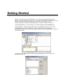
1) Start DAQFactory, or go File-New if you have already started DAQFactory.
2) Select Quick – Device Configuration from the DAQFactory main menu, then
select New Serial / Ethernet Device. This will open up the serial device
configuration window. For now we’ll ignore most of it since we just want to talk to
our device a little.
3) Click on either New Serial or New Ethernet depending on how you device
connects to your PC.
New Serial:
4) If you are doing a serial (RS-232, RS-422 or RS-485) connection: in the
window that appears, give your comm port a name, then specify the comm port
number and its parameters. This information is usually available from your
device’s manual. The default timeout value of 1000 is fine. Most likely flow
control will be off.
New Ethernet:
5) If you are doing an Ethernet connection: in the window that appears, give your
connection a name, then enter the IP address of the device. You will need to
configure your device with a valid IP on your subnet. The device manual should
explain how to do this. If you don’t know what a valid IP is, or for that matter
what subnet means, you should ask an IT person or get help from the device
manufacturer. There is also an Ethernet Primer at the end of this guide.
Next, you will need to enter the IP port. Ethernet is really a big bundle of
different communication lines. Each one is assigned a port number. Certain ports
have standard uses. For example, port 80 is typically used by the web for HTTP
requests. ModbusTCP is typically on port 502. Once again, you will need to
check with your device for the proper Ethernet port. If you don’t enter the correct
port, you will not be able to communicate with your device. Finally, a timeout of
1000 is more then adequate for most cases.
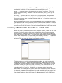
The Monitor Window
6) Once you have created your new port, click on the port in the port list so there
is a check next to it, and then click the monitor button. This will display the
DAQFactory serial monitor window. This window allows you to view the data
being transmitted and received on the serial line. It also allows you to manually
transmit data. This window is unique in several ways. First, it is what is called a
modeless window. This means you can keep the window displayed and
manipulate other parts of DAQFactory. In order to do much of that, though, you
will need to move the window to the side and close the serial configuration
window hiding underneath. Second, the monitor window displays binary data, or
data that can’t normally be seen (like carriage returns, line feeds, tabs, etc) as
three digit ASCII codes preceded by a backslash.
At this point we go in three directions depending on your device.
Streamed data:
If your device is a scale, or GPS or similar device that simply streams data out
without prompting (like a politician giving their opinion), then you should see data
appearing in the window immediately. If you don’t then chances are either your
device is not transmitting, or you have the communications parameters incorrect
and you should go back and check them. Just remember you can leave the
monitor window open while you tweak the settings.
Polled data with simple protocol:
If your device is of the more common sort that requires a little prodding, you will
need to send it a command using the manual output. Refer to your device’s
documentation and find a simple command you can send it. Enter that command
in the output box at the top and hit Send. If you need to enter control or binary
characters, put a backslash and the three digit code. For example, if you needed
to send it “Give me data” and a carriage return, you would put:
Give me data\013
13 is the ASCII code for carriage return, so \013 sends a carriage return at the
end. Other common codes are \010 for a line feed (LF), and \009 for tab. If you
have no idea what to send, start with a carriage return: \013. No matter what
you send, you should see what your output appear in the monitor error preceded
by “Tx:”, and hopefully your device’s response. If you don’t see what you
outputted and the Tx, then the connection failed. With serial RS232/422/485
comm ports, this usually means another piece of software is using the port or you
specified a non-existant port and you probably got an alert already indicating this.
With Ethernet, this means a connection could not be established, which means
either the IP address was wrong, or inaccessible, or the IP port was incorrect. Or
you just forgot to turn the device on. Either way, you should keep the monitor
window open and tweak your settings until you get it transmitting.
If you get Tx: and your output string but no response, then things are a little
better off. First, check your command and make sure you have it properly
formatted. Many devices don’t respond to invalid commands. Second, the
communications settings could still be off. With serial, this typically occurs when
you have the wrong baud or other setting. With Ethernet, it could be that you are
simply communicating with the wrong device because you put the wrong IP, or
your device has multiple Ethernet ports (some Ethernet encapsulation devices
have this), and you connected to the wrong one. Or, perhaps while you weren’t
looking your cat ate the cable. Again, leave the monitor window open, tweak your
settings, check your cable, and check the device’s manual. Until you get a
response, there is no point in moving forward with the rest of this guide.
Polled data with a complex protocol:
If your device uses a complex protocol, such as Modbus, you probably don’t know
off hand what a proper message is. If you do, perhaps you’d like a job with
AzeoTech? If not, fortunately we do work for AzeoTech and so here are a couple
example commands that might work. You could also simply jump ahead to the
section on prebuilt protocols, leaving the monitor window open.
ModbusRTU: assuming your device is at Modbus ID 1, to read the first holding
register do:
\001\003\000\000\000\001\132\010
ModbusTCP: you can actually send 6 characters and the device will likely echo it
back. But here is the same command as the above example for RTU using
ModbusTCP:
\000\000\000\000\000\006\001\003\000\000\000\001
Allen Bradley: assuming your device has an ID of 1 in CRC mode, to read N7:0
do:
\016\002\001\000\015\000\042\000\162\002\007\137\000\000\016\003\136\065
Mitsubishi FX serial: to read T0, do:
\0020080002\0035D
Mitsubishi uses a combined binary ASCII protocol, thus the combination of control
codes (\002 and \003) and ASCII characters.
For other devices or if you’d prefer to skip entering manual commands, you
should jump ahead to the section on prebuilt protocols, leaving the monitor
window open so you can see when the communications starts working. If
DAQFactory doesn’t have a prebuilt protocol for your device, you probably should
study the device’s instructions and manually calculate out a proper string. Usually
the CRC calc is the hard part, and you can always write a short sequence script to
do this.
At this point you should either be getting some sort of data from your device, or
you have a device with a complex protocol that you don’t know off the top of your
head, so you need to jump forward. If not, you really should go back to the last
few steps above and get things working.
Like above, there are three different courses of action next depending on your
device:
1) your device uses a protocol with an existing protocol driver included with
DAQFactory (for example the many flavors of Modbus)
2) your device uses a unique poll – response protocol. This means you have to
send the device a command, at which point it responds with some data
3) your device streams data to you unprovoked. You only need to interpret the
incoming data and probably never have to output anything.
Did we say three? We meant four: you have #2 and #3 combined. Some
protocols allow you to send a command that causes the device to switch to
streaming data continuously. Another command typically stops the streaming. In
this case, you’ll need to read twice as much as everyone else to learn to do both.
Don’t worry, its not that bad.
Using an existing protocol:
DAQFactory comes with an ever expanding list of protocol drivers that you can
use immediately. To use one of these drivers you should create a new serial /
Ethernet device as described above. You can either go all the way through the
procedure described above, or once you create your serial or Ethernet port, you
can simply select the desired protocol from the list, give your device a name, and
close the window. Once you do this, a new device will be available in the channel
table that will communicate on the port you specified using the protocol you
specified. In the channel table, you will see different I/O types available
depending on the protocol. You will also find different device functions available
depending on the protocol selected. At this point you should read the section in
the help on the desired protocol as it will describe what each I/O type and
function mean, as well as the proper addressing of your device.
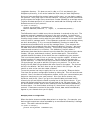
Creating a Poll / Response protocol
If an existing protocol is not available, you can create your own using DAQFactory
scripting. For most protocols this is a pretty simple task. To do so, click on the
New Protocol button in the Ethernet / Serial device window. This will open the
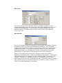
Protocol configuration window:
This window is very similar to the user device window, but that is not terribly
important at this time. At the top you should specify a name for your protocol.
This can be just about anything, though like all names in DAQFactory, it should
start with a letter and have only letters, numbers, or the underscore. You will
also have to specify a file name for the protocol. Protocols are stored separate to
your document in a text file. This allows you to use a protocol on multiple
documents and even share the protocol with other DAQFactory users. Because it
is stored in a separate file you will need to make sure and copy the protocol file if
you move your document to another computer. When specifying the protocol file,
you should make sure that the file ends in .ddp and stored in your DAQFactory
installation directory. If it does not end in .ddp, or if it is not placed in the
DAQFactory directory, it will not be loaded the next time you start DAQFactory.
Once you have specified the protocol name and file name, you can begin creating
the protocol. In a poll / response protocol, DAQFactory will send a command to
your device (polling it) and your device will send some data or an
acknowledgment back (the response). Fortunately, DAQFactory provides just the
function for doing this sort of thing. When you first create your protocol,
DAQFactory will automatically create several functions. Four of them are events
and start with “On” and we’ll talk about them later as they are only for advanced
protocols. The last is called “Poll”. Not only is the function created, but
DAQFactory even writes the function for you. You can click on Poll in the function
list and see the code. This was done to allow advanced users to tweak their
polling, or to use this script as a template for more advanced serial protocols. For
now, we’ll just use the function as is.
As an example, let’s say when your device gets the letter D followed by a carriage
return, it will respond with a data value and a carriage return. So, we need to
send the command D + carriage return, and then listen for the response. To
make the protocol easy to use, we also want this to be an I/O type so we can
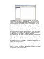
assign it to a channel. To create a new I/O type for this protocol, click on the Add
I/O Type button. A new window will appear:
Give your I/O type a name (say GetData) and leave the rest in their default
settings and hit OK. This adds the new I/O type to the protocol and gives a blank
box for entering code for this I/O Type. With the Poll function DAQFactory already
created for you, this is really easy and requires only one line of code:
return(StrToDouble(Poll("D"+chr(13),13)))
Starting from the inside we have “D” + chr(13). This is simply a string containing
D plus a carriage return (ASCII code 13). The chr() function simply takes an
ASCII code number and creates the corresponding character. The Poll() function
takes the string to output as its first parameter. The second parameter, 13, is the
end of line character for the reply from your device. The Poll() function will return
the entire string received up to this end of line character. So, moving out, we
take this string and send it to the StrToDouble() function which converts our
string into a number. So if the reply was “3248”, it would convert it to the
number 3248. In almost every case you’ll need to convert the string reply from
your device into a number. Finally, we return that number from our I/O type
function. This will put it in the channel.
To use this I/O type we have to apply the protocol to our new serial / Ethernet
device. First close the protocol configuration window by hitting OK. This will save
the new protocol. Now in the device configuration window, check your
communication port and put a check next to your new protocol. Give your device
a name, say, MyDevice, and hit OK. Now if you go to the channel table and
create a new channel you will see MyDevice listed in combo box in the Device
column. If you select the MyDevice device type you will see GetData in the I/O
type column. The D# and Channel number are not used in the code we wrote. If
you select a timing of 1 and hit apply, DAQFactory will start sending out D and
carriage return every second waiting for a reply. If you open the monitor on the
comm port you will see this.
That is the simplest of polling routines, and in many cases this is all you need. If
you had different commands to get different values, you would simply create
more I/O types and send a different command to the Poll function.
Getting a little more advanced, we’ll assume that your device has multiple
channels. Let’s say the command is still “D”, but with the channel number after.
For example, D5 plus carriage return would return the data from channel 5 on
your device. Ideally we want to use a single I/O type function and use the
channel number specified in the channel table. Fortunately, DAQFactory passes
several private variables to your I/O type function that describe the channel. This
includes the device number, channel number and more. For now, we’ll just use
the channel number. Fortunately, the code isn’t that much more complicated. To
make it easier to read, though, we’ll split it into a couple lines:
private string dataout = "D" + DoubleToStr(Channel) + Chr(13)
return(StrToDouble(Poll(dataout,13)))
The first line creates the output string. Its just like before, but we put the
channel in the middle. The Channel variable is a number, so we need to convert it
to a string too using the DoubleToStr() function. Then, we simply call the Poll()
function again, and return the result converted to a number. That’s it! Now you
can create multiple channels with the same I/O type and different channel
numbers and different commands will be sent to your device.
So far, we’ve assumed your device simply returns a number and a carriage return.
Most devices return extra stuff we don’t want. Often times this is simply the
command echoed back. Lets say our device returns “D” plus the value and a
carriage return. In this case we can’t just convert the result of the Poll() function
to a number because D doesn’t convert to any number in decimal. So we have to
change the code a little. Keeping it readable by splitting it into separate lines, it
would look like this:
private string dataout = "D" + DoubleToStr(Channel) + Chr(13)
private string datain = Poll(dataout,13)
return(StrToDouble(Mid(datain,1,10)))
Now lets get even more complicated and assume your device returns more than
one value with a single request. In this case, we’ll use a single channel to trigger
the read and then push the data into multiple channels. As an example, lets say
your device is polled with our original “D” plus carriage return, and it returns a
comma delimited list of 3 values followed by a carriage return. We’ll use channel
# 0 of our I/O type to trigger the read, and then put the data in channels 0,1 and
2:
if (Channel != 0)
return(NULL)
endif
private string datain = Poll("D"+Chr(13),13)
Channel.AddValue(strDevice,0,"GetData",1,StrToDouble(Parse(datain,1,",")))
Channel.AddValue(strDevice,0,"GetData",2,StrToDouble(Parse(datain,2,",")))
return(StrToDouble(Parse(datain,0,”,”)))
The first three lines ensure that we trigger the read from channel 0 only. This is
so we don’t have to worry about setting the Timing of channels 1 and 2 to 0.
Note that by returning NULL, we keep DAQFactory from adding a value to the
channel. The next line we do our standard Poll(). The following two lines stuff
the second and third values into channels 1 and 2. The Channel.AddValue()
function allows you to put data into a channel that you don’t know the name off.
It takes 5 parameters. The first 4 describe the channel (device type, device
number, I/O type, and channel number), the last contains the value to put in the
channel. strDevice is a local variable that contains the name of the device the
user created when using this protocol. You have to use strDevice because you
don’t know what a user might name their device. We then specified a D# of 0.
This means our channels will have to have a D# of 0, where previously it did not
matter. Next is a string with the name of our I/O Type. Finally we have the
channel number and the value to put in the channel. To retrieve the proper value,
we use the Parse() function. This function takes a string, the index into the string,
and the character used to delimit the string. In this case, the data is a comma
delimited string, and we want the second value (index 1 since its numbered from
0) for channel 1, and the third value for channel 2. Finally we return the first
value in the list to put it in channel 0.
That covers the primary types of poll / response protocols. Adapting to your
device is simply a matter of creating the correct output string and parsing the
input. Some protocols require more advanced functionality and that, along with
the details of how the Poll() function works is described at the end of this guide.
Binary and fixed field protocols:
But first, we should talk a little more about binary protocols. The protocols so far
have been primarily ASCII protocols. The only binary information is the carriage
return that marks the end of the line of data. What if, instead of “D3” + chr(13)
to read the 3rd channel with an ASCII string response, we had to send the binary
value 15 to trigger a read, and a word representation of the channel, for a total of
3 bytes, and then read a 5 byte response, the command byte (15) plus a 4 digit
double word representation of the number? Well, we’d have to do a few things
differently. We’d still construct our query as a string, but we’d use some different
functions:
private string dataout = chr(15) + chra(From.Word(Channel))
This looks similar to our previous example when we did “D” plus the channel
number in ASCII string form, except this time we use the From.Word() function.
The From. functions are a series of functions that convert numbers into their byte
representation. There are 16 different functions for the various ways a number
can be represented. In this case, we want the word with default LSB first
representation. The From functions return an array of numbers, so to convert it
into a string, we use the chra() function. This is just like the chr() function,
except it takes an array of values and returns a single string made up of the
characters in the array. If you did just chr() with an array of values, it would
return an array of strings.
It is important to understand that just because dataout is a string, it doesn't mean
it can't be a bunch of unreadable binary codes. The string simply provides a
simple way to manipulate these codes. We could do the same thing by creating
an array of all our values, but would have to convert the array to a string to call
any of the communication functions. As it happens, it is sometimes more useful
to do this. It is entirely up to you.
Moving on, the protocol in our example is different from the previous examples
not only because it is entirely binary, but because it is has a fixed length response
and doesn't have an end of line character. The Poll function is written to read to
an end of line character. So, to read a fixed number of characters, we'll need to
modify the Poll function slightly. Fortunately, all we need to do is change one line.
If you click on the Poll function in the protocol editor you will see all the code for
the Poll function. Skipping the details of the code, which is discussed later,
change the one line that says:
in = ReadUntil(until)
to
in = Read(until)
The Read() function takes a single parameter which is the number of characters to
read, so now our Poll() function's second parameter is the number of characters
to read instead of the end of line character. So, the next line of our I/O type
would be:
private string datain = Poll(dataout,5)
The 5 is the number of characters to read. Now all we need to do is parse the
data:
return(To.Long(AscA(Mid(datain,1,4)))
There are a bunch of functions here, so starting from the inside:
Mid(datain,1,4) returns the 2nd through 5th characters, thus skipping the first
code which should be 15, our command code echoed back to us.
AscA(...) converts those 4 characters into an array of 4 numbers. This is the
exact opposite of ChrA(). Actually, if you did ChrA(AscA("abc")) you'd get the
string "abc".
To.Long(...) converts an array of bytes to a single long value, which we then
return. The To. functions are the opposite of the From. functions. From.
functions convert a from a number to bytes, while the To. functions convert to a
number from bytes.
Binary protocols aren't much more complicated than ASCII protocols as long as
you remember that a string is just a series of numbers, each between 0 and 255.
Fixed field length protocols are equally easy, though you need to make a small
modification to the Poll function, but that's why we coded it in DAQFactory script.
Creating a Protocol to Accept non-polled Data
While the majority of devices use the poll / response method, there are still a fair
number of common devices that simply stream their data without prompting.
Some common examples of this are GPS devices (and most anything that uses
the NMEA protocol), and scales. For these types of devices we use the OnReceive
event of an user protocol to capture and parse data as it comes in. To create an
user protocol, click on the New Protocol button in the Ethernet / Serial device
window. This will open the Protocol configuration window:
This window is very similar to the user device window, but that is not terribly
important at this time. At the top you should specify a name for your protocol.
This can be just about anything, though like all names in DAQFactory, it should
start with a letter and have only letters, numbers, or the underscore. You will
also have to specify a file name for the protocol. Protocols are stored separate to
your document in a text file. This allows you to use a protocol on multiple
documents and even share the protocol with other DAQFactory users. Because it
is stored in a separate file you will need to make sure and copy the protocol file if
you move your document to another computer. When specifying the protocol file,
you should make sure that the file ends in .ddp and stored in your DAQFactory
installation directory. If it does not end in .ddp, or if it is not placed in the
DAQFactory directory, it will not be loaded the next time you start DAQFactory.
Once you have specified the protocol name and file name, you can begin creating
the protocol. Let’s jump right in with an example. Let’s say you have a scale that
simply outputs the weight every second as a number followed by a carriage return.
To parse this data and put it in a channel we would add the following code to the
OnReceive event of your protocol:
if (strIn == Chr(13))
private string datain = ReadUntil(13)
Channel.AddValue(strDevice, 0, "Input", 0, StrToDouble(DataIn))
Endif
The OnReceive event is called every time a character is received on the port. The
character received is passed to the event in the strIn variable. In the first line
above, we look to see if the last character received is a carriage return. The chr()
function simply creates a string with the given ASCII character, in this case ASCII
code 13 which is carriage return. If the character received is not a carriage return,
we don’t do anything. If it is, we use the ReadUntil() function to read all the
characters accumulated so far up until the carriage return. Then we parse the
data and put it into a channel using the Channel.AddValue() function. We parse
the data with the StrToDouble() function. This function simply takes the string
response and converts it to a number. The AddValue() function takes 4
parameters that describe the channel to put the data into (the device type, device
number, I/O type, and channel number), and the data point. The strDevice
variable contains the name of the device the user created using your protocol.
This is not known ahead of time, so you have to use this variable. A device and
channel number of 0 was chosen arbitrarily. The I/O type of Input was also
chosen arbitrarily. In order for the user to be able to create a channel with this
I/O type though, we need to add this I/O type to our protocol. To do this, we
simply click the Add I/O type button and enter Input for the name. The rest can
be left in its defaults. We don’t have to put any code in this I/O type. We just
need it to exist so the user can create a channel.
To use this protocol we have to apply the it to our new serial / Ethernet device.
First close the protocol configuration window by hitting OK. This will save the new
protocol. Now in the device configuration window, check your communication port
and put a check next to your new protocol. Give your device a name, say,
MyDevice, and hit OK. Now if you go to the channel table and create a new
channel you will see MyDevice listed in combo box in the Device column. If you
select the MyDevice device type you will see Input in the I/O type column. The
D# and Channel number have to be 0 because of how we coded the AddValue()
function above. You should select a timing of 0 since there is no polling in this
protocol. If data were received in the proper format, data would automatically
appear in your channel when you hit Apply.
Multiple points on a single line:
Often the device streams multiple data points in a single line. For example, your
device might output two values separated by a comma and followed by a carriage
return. The code is almost the same:
if (strIn == Chr(13))
private string datain = ReadUntil(13)
Channel.AddValue(strDevice, 0,"Input",0, StrToDouble(Parse(DataIn,0,",")))
Channel.AddValue(strDevice, 0,"Input",1, StrToDouble(Parse(DataIn,1,",")))
Endif
All we added was the Parse() function to split the data apart and then two calls to
AddValue to put the data into channels 0 and 1. The Parse command takes 3
parameters, the string to parse, the index you want to retrieve and the delimiter.
Varying data types:
A slightly more advanced streaming protocol is the NMEA standard often used in
devices like GPS. In this case different lines of data are received with different
meanings. The meaning of a particular line is determined by the first 6 characters.
To parse this, we simply look at these first six characters and put the data in
different places depending on this header’s value. You can delineate different
places using either different I/O types or different device numbers. For example:
if (strIn == chr(10))
// now read until the LF
private string datain = ReadUntil(10)
// split out header
private string head = Left(datain,6)
// now examine each line type differently.
switch
case (head == "$GPRMC")
Channel.AddValue(strDevice, 0, "RMC",
Channel.AddValue(strDevice, 0, "RMC",
case (head == "$GPGSA")
Channel.AddValue(strDevice, 0, "GSA",
Channel.AddValue(strDevice, 0, "GSA",
endswitch
endif
0, Parse(datain,1, ",")
1, Parse(datain,2, ",")
0, Parse(datain,1, ",")
1, Parse(datain,2, ",")
If your data is binary, you may want to review the section on Binary Protocols at
the end of the section on Poll / Response protocols to learn about the To and From
series of functions.
Poll / Response and streaming data:
Some devices perform both poll / response type commands and streaming data.
Typically they start in poll / response mode and a particular command will start it
streaming. The streaming continues until another command is sent to the device.
Handling these types of devices is almost entirely a matter of combining the
concepts described above. The exception is that you have to use a flag to keep
the OnReceive event from parsing data when the device isn’t streaming. To do
this you will first need to create the variable for the flag. For this you can use a
local variable. A local variable is similar to a private variable, but it is viewable by
any code in the protocol. It is not viewable outside the protocol. Typically you
will want to declare your local variables in the OnLoad event. Something like this:
local streamflag = 0
Then, in the OnReceive event, you would enclose your stream parsing code with a
simple if:
if (streamflag)
… parse data, we’re streaming
endif
Of course you’ll need to set and clear the streamflag from somewhere. This can
be done in the code that sends the stream start and stop commands to the device.
Advanced Communications
The Poll() function in detail:
Here is the script for the poll function with line numbers:
1
2
3
4
5
6
7
8
9
10
11
12
13
14
15
16
17
18
19
20
21
22
23
24
25
26
27
28
29
30
31
function Poll(string out, until)
// this function will poll the port with given string and read
// the response until the given character. Returns NULL (empty)
// if there is an error
if (argc < 2)
throw("Invalid number of parameters")
endif
private string in
try
// lock the port
if (!LockPort())
throw("Unable to lock port")
endif
// clear anything pending
Purge()
// output our string
Write(out)
// and read until the eol:
in = ReadUntil(until)
// release the port
UnlockPort()
// and return the response
return(in)
catch()
// error occured
UnlockPort()
throw()
endcatch
// return NULL to indicate error. This should never happen
// because of the throw() statement above
return(NULL)
The first line is a standard function declaration. Its not required, but it allows us
to quickly name the two parameters of this function, out and until. Lines 5
through 7 ensure that there were actually two parameters passed in. Argc is a
private variable set in all functions that contains the number of parameters passed.
If there are less then two passed in, we throw an error.
Next we have to lock the port in line 11. Locking the port prevents another
sequence or thread from trying to communicate over the port while we are in the
middle of a poll / response cycle. If we didn’t lock the port, we could have a case
where we send the device a command, and another thread sends another
command before we get a response. If this happened the response may not
match our request. The LockPort() function doesn’t always succeed. If the port is
being over used, the port may not come available within the timeout specified in
the port. In this case, LockPort() returns 0 and we throw an error. We can’t do
anything else, otherwise we’d defeat the purpose of locking the port in the first
place.
In line 15 we purge the port. This clears out any extraneous data on the port and
is usually a good idea just to be sure nothing is left over from a previous request.
Once purged, we can write the string out in line 17. We can then immediately
read the data back in line 19. The readuntil() function reads from the port until
the given character is received or the timeout occurs. If the timeout does occur,
an error is thrown. Otherwise, the characters are returned and placed in the
variable. Once we have a response, we can unlock the port in line 21 and return
the string received in line 23.
If we don’t unlock the port after locking it, no other sequences or threads will be
able to communicate on the port. For this reason, immediately after locking the
port, we enclose all the code up to the UnlockPort() in a try/catch block (lines 9 to
24). If an error is thrown inside this block, DAQFactory will skip to line 26 where
it unlocks the port. We then rethrow the error in line 27 so the user knows
something happened. This format ensures that the port is properly unlocked.
As stated in the comments in the code, line 31 is not really necessary as it is
impossible to reach, but we placed it there anyway just in case the logic changed
in the rest of the script. This ensures that something is actually returned from the
function, even if its nothing.
Ethernet Primer
Since an IT person may not be available, here is a quick explanation of Ethernet
communications and IP addressing and a few pointers at the end. Ethernet
communications can be complicated, especially in large corporations. If you do
not feel comfortable with this, you should contact an IT person. Assigning an
incorrect IP address may bump another individual off the network and is not a
good way to make friends.
Ethernet communications, as explained previously, is a serial communications
method, meaning bits of data are sent one after another and assembled to create
bytes of data. A bit is simply a one or a zero. A byte is a collection of 8 bits that
describe a number between 0 and 255. Often, a byte is used to describe a
character, a letter, number, symbol or code. So, for example, a capital A is
typically coded as 65. This code is called the ASCII code and you can see the
standard characters by searching for ASCII on the internet. Note that only the
numbers from 0 to 127 have standard meanings. The numbers above 127 are
used for a wide variety of things, often to generate non-english characters.
But we deviate from Ethernet… Ethernet is actually made of multiple layers. The
details of what these layers are is not so important. The important ones are the
hardware layer, the IP layer, and the TCP/UDP layer. The hardware layer is the
what it seems. Typically this is Ethernet cabling, switches and routers, but could
also be fiber optic cable, DSL lines, GPRS, etc. In general, you do not need to
worry about the hardware layer, except for proper cabling. Fortunately, there is
usually only two different types of cabling: direct and crossover. In most LAN’s
you will use exclusively direct cabling. This means that each pin on one side of
the cable corresponds to the same pin on the other side of the cable. In a
crossover cable, several pairs of pins are swapped. You would use a crossover
cable if you wanted to connect your PC directly to your Ethernet device (PLC, DAQ
device) without going through a switch, hub, or router. A switch or hub is simply
a traffic cop who allows Ethernet traffic to pass through to the appropriate spots.
Often switches/hubs are combined with your cable or DSL modem to allow
multiple computers to connect to the same internet connection.
On top of the hardware layer runs the IP layer. The IP layer handles the
addressing, thus the “IP Address”. The IP address is a collection of 4 numbers,
each between 0 and 255, separated by periods. These 4 numbers actually define
a single big number internally that ranges from 0 to a little over 4 billion, but
splitting that number into 4 sections makes it easier for us to read. A URL, such
as www.azeotech.com, is not an IP address. In fact, before your computer can
find azeotech.com it has to go to what is called a domain name server (DNS) to
find the IP address that corresponds to azeotech.com. Domain name servers are
typically provided by your ISP and their sole job is to take a URL and translate it
into the IP address. Ethernet cannot use URLs directly.
IP addresses are addresses and therefore every computer on the Internet has a
unique IP address. On the Internet, these addresses are distributed by a global
governing body, and typically provided to you by your ISP. Since IP addresses
basically define a number between 0 and about 4 billion, there can only be about
4 billion computers directly connected to the Internet. Fortunately there are
things called routers which allow you to connect multiple computers on a LAN
(local area network) to a single IP address on the internet. Each computer on the
LAN has its own IP address, but in order to communicate with computers on the
internet the computer has to connect to the LAN’s router, called a gateway first.
In addition to allowing multiple computers to connect to the internet using one
global Internet IP address, routers also provide a level of security. Each computer
in the LAN has a private IP address. This address typically starts with 10. or
192.168. IP addresses that start with these numbers are called non-routable IP
addresses and used exclusively in LAN’s. If your computer has an address
starting with one of these numbers then it cannot be accessed from the Internet
without using special tools like VPN (virtual private networking) or a virus. Since
your computer isn’t visible from the outside, it is somewhat protected by the
router. The most common security problem occurs when you get a virus. This
virus runs on your computer and announces to the world (or at least the virus
author) “Here I am!” and creates a link from the inside, much as you would when
you access a web site.
Now, how does your computer know when to look for an IP address that is on the
LAN, for example, a printer, or local file server, and when to go to the gateway
router to access an external computer? This is where the subnet comes in. The
subnet tells your computer which computers are directly accessible and which
computers are only accessible through the gateway. In general, subnets are
specified as 255.255.255.0 or 255.255.0.0 or 255.0.0.0. In the first case, the
subnet includes all addresses with the same first three numbers. So, 192.168.1.1
and 192.168.1.2 would be on the same subnet, but 192.168.2.1 would not and in
order to access that address, your computer would have to ask the gateway,
which would have to somehow have access to that subnet as well, presumably by
having a subnet of 255.255.0.0, which includes all addresses with the same first
two numbers. There are other combinations that don’t include 255, but this gets
much more complicated to figure out and are pretty rare. Typically, in small
LAN’s you will have a single subnet, but if you are in a large corporation, you may
have multiple subnets for different parts of your company. This allows each part
to secure their own network and control their resources. If you are in this
situation, you almost certainly have IT people and should talk to them before
putting anything on the LAN.
Finally, on top of the IP layer there is the TCP/UDP layer. TCP and UDP are two
different methods for data transmission. TCP is what is called a guaranteed
delivery protocol. This means that if you send a packet over TCP to a device, the
Ethernet layers below will keep trying to deliver that packet until it is delivered or
a timeout period occurs. If it is not delivered, then the sending computer is
notified and can take appropriate action. This is the most common method. UDP
is a broadcast protocol. With UDP, the packet is sent without regard to whether it
is received or not. UDP is often used to find out what devices are connected to a
subnet. So, for example, a piece of software could send a UDP command to every
IP address on the local subnet that tells the device to send a response. Then, it
can simply wait for responses and find out who is actually connected.
As mentioned before, just to complicate things, in addition to the IP address,
there are ports on each address. The port is like a communications channel.
Each IP address has 65535 ports available. Some of these ports are used for
common things. For example, HTTP, the protocol used to get web pages, uses
port 80. Most ports are picked arbitrarily by various software packages or
hardware devices. You have to have both the correct IP address and port to
communicate with a device over Ethernet.
One final discussion: static versus dynamic IP addressing. To make the
installation of new PC’s easier on the IT people, something called DHCP was
invented. DHCP is a protocol used to automatically provide IP addresses to
devices. The DHCP retains a list of IP addresses that can be used and when a
new computer connects to the LAN, it finds the DHCP server and requests an IP
address to use. This address is called a dynamic IP address. It is dynamic
because the next time the PC or device is powered up and requests an address
from the DHCP server, it may be a different address. A static IP address is
specified directly on the PC or device and is fixed. Dynamic IP addresses work
because most of the stuff people do on PC’s are client based, meaning they start
the communications and connect to a server or other device with a known fixed IP
address. If your PC or device has a dynamic IP address, you cannot access it
externally because you don’t know its address. It would be like trying to
telephone somebody whose telephone number changed every day.
Dynamic IPs are also used by ISP’s to stretch the number of users they can have
on a group of static IPs. The ISP might own 100 IP addresses and have 200
subscribers. But not all 200 subscribers are on the Internet at the same time, so
they rotate IPs among those that are connected. Since much web browsing is a
connect, download, and release mechanism, it is pretty easy to rotate IPs even if
200 people are browsing the web at the same time.
Now the important points:
1) To connect to an Ethernet device using DAQFactory and TCP, you must know
the IP address of the remote device. The IP address also must be accessible
from your subnet. So if your device has an IP of 192.168.1.2 and you have an
IP of 10.0.0.3 and your subnet is 255.0.0.0, you probably won’t be able to
connect to your device. When you first start, you should always try and put
your device on the same subnet so you don’t have to worry about routing.
2) You also must know the port number of the TCP/IP connection that your
device is listening on. Many devices listen to multiple ports using different
protocols, so make sure you get the right port.
3) In order to put a device on the Internet in a way that allows access to that
device, the device must have a static, Internet capable, address. This means
the address can’t start with 192.168 or 10. You will have to contact your ISP
or IT people for a static IP address, and it may cost extra. This is a very
insecure method. Alternatively, you can use a technology like VPN to access
your LAN and then get access to the local addresses. In this case, your device
will still have to have a static IP, but it can be a local address, i.e. one that
starts with 192.168 or 10. VPN typically requires a special type of hardware
firewall. VPN is much more secure then simply giving your device a static IP
on the internet.
4) The only way to connect a PC directly to a device without using a switch, hub
or router is to use a crossover cable. In this case, you will need both the
device and the PC to have IP addresses on the same subnet. Your best bet is
to simply use 192.168.1.2 and 192.168.1.3, but it doesn’t really matter
because there are no other computers or devices to interfere with.
5) Some devices require a crossover cable to initially set the IP address. The
device may come from the factory with an IP of 192.168.1.1 or similar. You
will probably not want to simply plug this device into your LAN. Instead, you
should connect directly to the device with a crossover cable and assign your
PC an IP address on the same subnet, 192.168.1.2 for example.
6) Be careful when you have multiple Ethernet connections. This is especially
common on laptops that have both a wireless and wired connection.
Depending on your settings, the two connections may be on completely
different subnets which may prevent a connection.
7) An easy way to tell if you have access to a device is to ping it. Not all devices
support ping, but most do. To perform a ping, open a command line prompt,
which is typically under Start – Programs –Accessories – Command Prompt.
Type in something like: ping 192.168.1.1 to ping a particular address. You
will probably get one of three responses:
A) It will pause and say “Request timed out.”. This means either the IP
can’t be found or can’t be accessed, or the device does not support the
ping function.
B) It will display something like: “address is unaccessible”. This means
you are not on the same subnet as the IP specified and either your
gateway doesn’t exist, or it doesn’t know how to get to that address
either. This can also occur if you are using DHCP on your PC and your
PC hasn’t gotten its IP address yet.
C) It will display something like: “Reply from 192.168.1.1: bytes=32
time=1ms TTL=63”. This means you can successfully reach the device.
Whether or not it is actually the device you want is another question,
but chances are, you are successful. Now the trick is determining
which port to connect to, and for that you’ll have to review your
devices manual.