1
Siemens Industry, Inc.
Software Release Memo
SR353-10
Rev: 5
August 2010
Procidia™ Controller Models 352P, 353, 354, and 354N
Design Level “A”
MPU Controller Board Firmware, Version 3.00
PRODUCTS INVOLVED
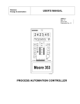
Model 353 Process Automation Controller, Design Level A 1 , (e.g. 353_ _ _ _ _ _ _ _ _ _A_)
Model 352Plus™ Single-Loop Digital Controller
Model 354 Universal Control Station
Model 354N Universal Loop Controller
INTRODUCTION
This Software Release memo discusses the enhancements and operational considerations for version 3.00
of MPU Controller board firmware (software).
ENHANCEMENTS
Model 353, Design Level “A” controllers: V3.00 firmware adds Ethernet communication function
blocks and V2.00 Ethernet Communication board firmware to the features provided by earlier firmware
versions. An Ethernet Communication option board with V2.00 firmware must be installed in a Model
353 controller for the added blocks to be available. Of the four listed controllers, Ethernet
communications is available only in the Model 353.
V3.00 firmware will add the following enhancements to a Model 353.
•
AWE Function Block – The AWE (Analog Write Ethernet) block allows the controller to write
analog data to other Modbus devices over the Ethernet network.
•
CWE Function Block – The CWE (Coil Write Ethernet) block allows the controller to write coil data
to other Modbus devices over the Ethernet network.
•
DWE Function Block – The DWE (Digital Write Ethernet) block allows the controller to write digital
data to other Modbus devices over the Ethernet network.
•
V2.00 Ethernet Communication board firmware (included in this release)
•
V3.00 Controller firmware enhances AIE, CIE, and DIE function blocks through the inclusion of
additional parameters for data type selection.
All listed controllers: The RLM block now accepts an adaptive rate input.
1
The design level is indicated by the next to last character in the model number. The characters shown are those
required to identify an involved instrument. See the Siemens Process Instruments catalog or the instrument’s User’s
Manual (e.g. UM353-1) for complete model designation information.
SR353-10
OPERATIONAL CONSIDERATIONS
•
353 with Ethernet - Before installing MPU Controller board firmware 3.00, if the controller contains
an Ethernet Board with firmware version 1, first upgrade Ethernet Board firmware to version 2. To
display the firmware version, refer to the STATN – Station Parameters section in the Function Blocks
chapter of UM353-1, the controller’s User’s Manual.
•
Critical configurations 2 only – Before upgrading to MPU Controller board firmware 3.00:
1) Save the current configuration using i|config™.
2) Using the Display Assembly/Local Faceplate, select and store FCO-0 (zero) as the controller
configuration -- FCO-0 will overwrite the installed configuration.
3) Update the MPU Controller board firmware.
4) Create a new configuration using the saved configuration for a reference.
•
Before installing MPU Controller board firmware that is a lower level than that presently installed in
the controller:
1) Save the current configuration using i|config.
2) Using the Display Assembly/Local Faceplate, select and store FCO-0 (zero) as the controller
configuration -- FCO-0 will overwrite the installed configuration.
3) Install the Controller board firmware.
4) Create a new configuration using the saved configuration for a reference.
•
RTC/CB Option Board - After downloading a configuration to a controller that has an RTC/CB board
installed, an “RTC->MEM” message may appear following a power interruption. If the
"RTC->MEM" message appears, the controller is asking for permission to transfer the configuration
data from the RTC/CB to the MPU board. The presently selected choice (YES or NO) is shown in the
5-digit display. Select "NO" using the pulser knob and press the "STORE" button, which will allow
the controller to operate. To stop the "RTC-MEM" message from appearing on future power cycles,
you should now store a configuration parameter using the controller’s Display Assembly/Local
Faceplate.
•
353 with Ethernet - After installing MPU Controller board firmware 3.00, if the controller
configuration includes an AIE function block connected to an AOE block, the BYTE ORD parameter
must be changed to 4 from the default setting of 1. Refer to function blocks “STATN- Station
Parameter” and “AIE_- Analog Input – Ethernet” in UM353-1 for details.
•
ALARM - Alarm Block – When an ALARM block is placed in a loop configuration (either at the
controller faceplate or in i|config™), Alarm 3 is configured as a Deviation alarm. The displayed
default value of Alarm 3 Limit is 100%. However, the alarm will actually trip at 110%. To reset the
default Limit value to 100%, display the Alarm 3 Limit value and press STORE (faceplate) or click
Accept (i|config).
When Alarm 3 Limit is user configured, the user entered value over writes the default value and the
default trip point error has no effect.
The above also occurs when creating a new configuration from a Factory Configured Option (FCO)
that contains an ALARM - Alarm Block, for example, FCO101. If the selected FCO has two loops,
the Alarm Block in each loop should be reset.
2
For the purpose of this Software Release memo, a critical configuration may be any configuration that would be
very difficult to recreate in the unlikely event that the upgrade process fails or is interrupted.
2
SR353-10
•
In the STATN - Station Parameters function block, parameters CONFG LO and PARAM LO can
have a value of either 0 or 1, 2, or 3: a 0 allows writes, a 1, 2, or 3 prevents writes. (There is no
difference in operation in selecting a 1, 2, or 3.) Early User’s Manuals list write values as YES/NO
which was correct for earlier firmware. Later User’s Manuals incorrectly list different functions for
selections 1, 2, and 3. Reads are always enabled.
UPGRADE CONSIDERATIONS AND MATERIALS
1. Check the current MPU Controller Board firmware version before upgrading. To display the
firmware version, refer to the STATN – Station Parameters section in the Function Blocks chapter of
the controller’s User’s Manual.
2. A personal computer running Microsoft® Windows® 95, 98, NT, 2000 or XP is needed.
3. Upgrading requires the following items:
1) Communications Cable - P/N 16353-61
2) Communications Cable Adapter; select one to mate with your computer’s COM port:
DB25 to MMJ11 - P/N 16353-62
DB9 to MMJ11 - P/N 16353-63
3) Model 352P/353/354 Firmware Upgrade Utility P/N15939-77V3.00 (upgrades 1.xx to 3.00). Kit
contents:
• CD-ROM with the multiple versions of the controller firmware
• Software license disk created for the station (by serial number) to be upgraded
• Software registration card
INSTALLING VERSION 3.00
1. Read the Operational Considerations and the Upgrade Considerations and Materials sections of this
publication.
2. Follow the instructions on the label of the supplied CD-ROM to install the utility.
3. Read the supplied HELP file for information about downloading firmware (kernel and code) to a
controller.
4. Complete and mail the software registration card.
3
SR353-10
CUSTOMER/PRODUCT SUPPORT
For support and the location of your local Siemens representative, refer to the table below for the URL of
the Process Instrumentation (PI) portion of the Siemens public Internet site. Once at the site, click
Support in the right column and then Product Support. Next select the type of support desired: sales,
technical (see the table below), documentation, or software.
Online Support Request
http://www.siemens.com/automation/support-request
Technical Support
1-800-333-7421; 8 a.m. to 4:45 p.m. eastern time, Monday through Friday (except
holidays)
Customer Service & Returns
1-800-365-8766 (warranty and non-warranty)
Public Internet Site
http://www.usa.siemens.com/pi
Technical Publications
in PDF
Click the above link to go to the PI home page. Click Support and then Manuals
and then, under “Additional Manuals,” select the product line (e.g. Control
Solutions)
All product designations may be trademarks or product names of Siemens Industry, Inc. or other supplier companies whose use
by third parties for their own purposes could violate the rights of the owners.
Siemens Industry, Inc. assumes no liability for errors or omissions in this document or for the application and use of information
in this document. The information herein is subject to change without notice.
Procedures in this document have been reviewed for compliance with applicable approval agency requirements and are
considered sound practice. Neither Siemens Industry, Inc. nor these agencies are responsible for product uses not included in the
approval certification(s) or for repairs or modifications made by the user.
© Copyright 2010, Siemens Industry, Inc. All rights reserved.
4