1
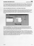
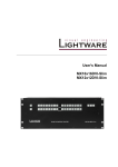
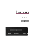
NL5000
Wireless Modem
NL5000 User Manual
Data Only Rev B0
Raveon Technologies Corporation
2461 Impala Drive
Carlsbad, CA 92010 - USA
Phone +1-760-444-5995
WWW.RAVEON.COM
WWW.RFNEULINK.COM
TABLE OF CONTENTS
1.0 Introduction ........................................................................................ 3
1.1 General ....................................................................................... 4
1.2 Model Identification ..................................................................... 3
1.3 FCC Regulations ........................................................................ 4
2.0 Specifications .................................................................................... 5
2.1 General ....................................................................................... 5
2.2 Transmitter ................................................................................. 6
2.3 Receiver ..................................................................................... 6
3.0 NL5000 I/O Connectors and Indicators ............................................ 7
3.1 15-Pin I/O Connector .................................................................. 7
3.2 Indicators .................................................................................... 8
3.3 NL5000 - DB 15 to DB 9 Interface Cable .................................... 9
4.0 Accessories........................................................................................ 9
5.0 Operation .......................................................................................... 10
5.1 Channel Selection ..................................................................... 10
5.2 Power Supply Voltage............................................................... 10
5.3 Duty Cycle/Key-Down Limitations ............................................. 11
5.4 Operating Modes ...................................................................... 12
5.5 Antenna Placement................................................................... 12
5.6 Analog/Voice Interface .............................................................. 13
5.7 Data Stream Packet Detection Modes ...................................... 13
NL5000 User Manual Rev B0
1
6.0 Configuration Software ................................................................... 14
6.1 PC Configuration Software Kit .................................................. 14
6.2 Loading The Configuration Software ......................................... 15
6.3 Computer Software Copyrights ................................................. 15
6.4 Using The Configuration Software ............................................ 15
6.5 Configuration Software Buttons ................................................ 16
6.6 Configuration Software Drop-Down Menus ............................... 17
APPENDIX ............................................................................................... 22
NL5000 User Manual Rev B0
2
1.0 Introduction
1.1
GENERAL
The NL5000 modem is a wireless modem designed to operate on the licensed land
mobile frequency bands at VHF, UHF, and 220 MHz. It supports over-the-air data
rates of up to 4800 bps in a 6.25 kHz channel, 9600 bps in a 12.5 kHz channel,
and 19.2 kbps in a 25 kHz channel. Besides offering data communications, the
NL5000 modem includes voice transceiver audio input and outputs. The complete
modem transceiver is housed in the standard NL5000 case, resulting in a light,
compact package.
1.2
MODEL IDENTIFICATION
The NL5000 modem has a part number in the form of “NL5000-VHF/LN”
Where:
The NL5000 is followed by the next major frequency band designator:
VHF
220 MHz
UHF
“L” is the Low portion of the sub-band designator:
L=136-162 for VHF and 400-420 for UHF
“H” is the High portion of the sub-band designator:
H=148-174 for VHF, and 450-470 for UHF
“N” designates the channel bandwidth:
S=6.25 kHz
N=12.5 kHz
W=25 kHz
Example: A NL5000-UHF/HN would be a UHF module for operation between 450
and 470 MHz, narrow (12.5 kHz channel spacing) IF bandwidth.
NL5000 User Manual Rev B0
3
1.3
FCC REGULATIONS
1.3.1 Licensing
The FCC requires that the radio owner obtain a station license for his radio before
using the equipment to transmit, but does not require an operating license or
permit. The station licensee is responsible for proper operation and maintenance of
his radio equipment, and for ensuring that transmitter power, frequency and
deviation are within the limits specified by the station license. This includes
checking the transmitter frequency and deviation periodically using appropriate
methods.
1.3.2 Equipment Authorization (Certification)
The unit is certified for transmission of either voice or data signals when aligned
according to the alignment procedure for the proper bandwidth and when operated
as a complete unit in the metal case. Operation of the RF board as a stand-alone
unit or in combination with any other equipment, in any mode outside the alignment
procedure, or with the clipper filter electronically disabled will require the filing of a
new certification application with the FCC by the user.
1.3.3 Standards
The FCC, with its action in General Docket 79-144, March 13, 1985, adopted a
safety standard for human exposure to radio frequency electromagnetic energy
emitted by FCC regulated equipment.
The NL5000 product family has been evaluated for compliance with the maximum
exposure limits for RF energy at the maximum power rating of the unit and with the
only antenna sold for use with this product by RF NEULINK. To ensure compliance
with the General Population/Uncontrolled maximum exposure limits, please
observe the following:
When the RF Neulink RAM-1545 remote magnetic mount antenna is used, mount
the antenna in a location that will ensure that all persons will be located 8.0 inches
away from the antenna of all models
Antennas other than the RF Neulink RAM-1545 must be tested with the NL5000 for
RF exposure compliance in the environment in which it is to be used per the FCC’s
OET Bulletin 65, Edition 97-01 or Industry Canada RSS-102.
NL5000 User Manual Rev B0
4
2.0 SPECIFICATIONS
2.1
GENERAL
FCC Rule Parts
IC Rule Parts
Data rate (bps)
6.25 kHz channel
12.5 kHz channel
25 kHz channel
Modulation
Voice
Data
Over-the-Air Protocol
Number of Channels
Operating Bandwidth
VHF
UHF
220 MHz
Synthesizer Step Size
VHF
UHF
220 MHz
Emissions Bandwidth
Voice
12.5 kHz channels
25 kHz channels
Data
6.25 kHz channels
12.25 kHz channels
25 kHz channels
Frequency Stability
-30°C to +50°C
-30°C to +60°C
-30°C to +75°C
Supply Voltage
D-version
I, L-versions
RF Connector
Power/Data Connector
Dimensions (LxWxH)
NL5000 User Manual Rev B0
90
RSS-119
4800 bps
9600 bps
19,200 bps
Direct FM
4FSK
RF Neulink Proprietary
2 (8 via software)
26 MHz
20 MHz
28 MHz
2.5 kHz
5.0/6.25 kHz
2.5/3.125 kHz
10.0 kHz
15.0 kHz
4.8 kHz
9.6 kHz
19.2 kHz
+/- 1.0 ppm
+/- 1.5 ppm
+/- 2.5 ppm
7.5+/-0.5 VDC
11-16 VDC
BNC
15-pin subminiature D-type
3.6"x 2.3" x1.0"
5
Weight
Indicators
2.2
TRANSMITTER
RF Output Power
VHF
UHF
220 MHz
RF Load Impedance
PTT attack time
Spurious and Harmonics
FM Hum and Noise
6.25 kHz channel
12.5 kHz channel
25 kHz channel
Current Drain
1 watt
2 watts
6 watts
2.3
6 oz
Transmit LED, Receive LED
1-6 watts
1-3 watts, 1-6 watts
1-6 watts
50 Ohms resistive, VSWR 1.5:1 or less
15 ms max.
-25 dBm max.
35 dB min.
40 dB min.
45 dB min.
1.1 A max.
1.6 A max.
2.7 A max.
RECEIVER
Sensitivity
Voice (12 dB SINAD)
Data (10-5 BER)
Adjacent Channel Selectivity
6.25 kHz channel
12.5 kHz channel
25 kHz channel
Spurious and Image Rejection
IMD Rejection
FM Hum and Noise
6.25 kHz channel
12.5 kHz channel
25 kHz channel
Conducted Emissions
Squelch Attack Time
Receive Current Drain
NL5000 User Manual Rev B0
0.25 uV max.
0.30 uV max.
50 dB min.
60 dB min.
70 dB min.
70 dB min.
67 dB min.
35 dB min.
40 dB min.
45 dB min.
-57 dBm max.
15 ms max.
120 mA max.
6
3.0 NL5000 I/O CONNECTOR AND INDICATORS
3.1
15-PIN I/O CONNECTOR - DATA ONLY
Connector Pinout
Pin
1
2
3
4
5
6
7
8
9
10
11
12
13
14
15
Name
Description
A/B
NC
Supply
NC
RD
TD
CTS
DSR
TEST
CD
RTS
GND
Input
Input
Output
Output
Input
Output
Output
Input
Output
Input
Comments
Not used for Data
Not used for Data
Not used for Data
Channel 1/2 or High/Low power
Not Used
DC Power + input connects here to power unit
Receiver Alignment-Do NOT CONNECT
RS-232 data output from modem
RS-232 data input to the modem
RS-232 clear to send output from modem
RS-232 data set ready output from modem
Used for PTT (Not used for Data)
Carrier Detect
RS-232 request to send input to modem
System ground - Power Supply I/P connection
Pinout Description – DB 15
Pin 4
A/B
Depending on how it is programmed via the Configuration Software, this pin can
either be a channel A/channel B selection pin or a high/low transmit power
selection pin. This pin has an internal pull-up resistor to +5 volts and assumes a
high (channel A or high power) state when left unconnected.
Pin 5
Not Used
Pin 6
SUPPLY
This is the positive power supply input for the modem.
Pin 8
RD (Receive Data)
RS-232 data to be received from the modem is available at this pin. The data are
at normal RS-232 levels and are transmitted from the modem to be received by
the host computer or other device connected to the modem. The radio accepts
port speeds from 2,400 bps 38,400 bps.
NL5000 User Manual Rev B0
7
Pin 9
TD (Transmit Data)
RS-232 data to be transmitted to the modem should be presented to this pin. The
data should be at normal RS-232 levels and are transmitted from the host
computer or other devices to the modem.
Pin 10
CTS (Clear to Send)
This RS-232 output pin is asserted by the modem as a response to an assertion of
the RTS pin when it is ready and able to receive data from the host computer or
device.
Pin 11
DSR (Data Set Ready)
This RS-232 output pin is asserted by the modem when it is powered-up. It
indicates that the modem is actually connected, although not necessarily ready to
receive data. The polarity (active low/active high) is programmable via the
Configuration Software.
Pin 13
CD (Carrier Detect)
This pin is asserted by the modem when the receiver has detected a carrier. The
RF level set point is set via the Configuration Software. Note that the modem
demodulation circuitry does not actually use this signal to determine that a valid
data packet has been received. The polarity (active low/active high) is
programmable via the Configuration Software
Pin 14
RTS (Request to Send)
This RS-232 input pin is asserted by the host computer or device to indicate that it
has data to be transmitted by the modem. If the modem is able to accept the data,
the CTS pin will be asserted in response.
Pin 15
GND (Ground)
The system ground common point and negative connection for the power
supply input.
3.2
INDICATORS
The NL5000 Modem has two indicators on the side of the unit, one green RX LED
and one red TX LED. They function as follows:
GREEN RX LED This indicator is illuminated when the modem has detected a
valid preamble for a data packet. This indicator reflects the behavior of the
NL5000 User Manual Rev B0
8
modem’s packet detection system, not the fact that a signal may actually be
present. To determine the presence of a carrier, one can monitor the state of the
Carrier Detect output.
RED TX LED This indicator is illuminated when the modem is transmitting.
3.3
NL5000 - DB 15 to DB 9 Interface Cable
DB 15 Male
1
2
3
4
NL5000 Serial Interface Cable
DB 9 Female
9 Tx Data
DCD
DSR
Rx Data
RTS
Tx Data
CTS
10 CTS
11 DSR
12
5
6
13 DCD
D1
14 RTS
7
8
15
Rx Data
6
1
2
7
3
8
4
GND
WHT
A/B Ch.
RED
+12 VDC
BLK
9
5
GND
The above interface cable facilitates the connection of standard RS-232 signals to
a typical 9 pin “D” type female connector. This cable additionally accommodates
the connection of the +12 VDC, Ground and the A/B power or channel selector to
the 15 pin “D” type female connector on the NL5000 front panel. As shown, D1 is
placed in series between pin 6 and the + 12 VDC supply voltage and provides
reverse polarity protection.
4.0 ACCESSORIES
Note: Configuration Software kits are for use by authorized
service/maintenance personnel only.
The Configuration Software Kit for NL5000 (via compatible computer) is model
NL5000P-PCKT. It includes:
1. Configuration Software disk, CD (qty 1).
2. A Configuration Software/Power cable with a DB-15 Male connector on one
end for connection to the NL5000 modem and a cable to a DB-9 Female
connector for connection to the host computer and two wires, one red (positive)
and one black (negative) for connections to a power supply.
Factory Configuration of channels and features is also optional. Contact the factory
for details.
NL5000 User Manual Rev B0
9
5.0 OPERATION
5.1
CHANNEL SELECTION
Via the 15-pin connector, the NL5000 supports one channel if the A/B pin (pin 4) is
programmed for high/low power and two channels if the A/B pin is programmed as
a channel select input. Channel A is set when the A/B pin is activated and the A/B
pin is in the logic high state i.e. above 3.5 volts DC or left unconnected (There is an
internal pull-up resistor on the A/B pin). Channel B is set when the A/B pin is
activated and the A/B pin is in the logic low state i.e. below 0.5 volts DC. If the A/B
pin is programmed for high/low power, channel A is always selected.
Internally, the NL5000 can store eight (8) channels. The first one or two are
selected via the 15-pin A/B pin, but the remaining channels can be selected within
the Configuration Software or via a special channel select command through the
RS-232 connection.
A change in the channel selection in receive will cause the receiver to operate on
the new channel. In transmit, however, the channel selection is only checked only
at the beginning of a transmission. Changes in channel during transmit will not
change the transmit operating channel of the unit until the unit is cycled from
transmit to receive and back to transmit.
5.2
POWER SUPPLY VOLTAGE
Pin 6 is the positive supply input to the unit. The type of module determines the
actual voltage that should be applied to this pin. One should be absolutely sure of
the proper voltage and current requirements before applying power.
Three voltages are used within the unit; +5 volts for the processor and logic circuits
along with most of the receiver, +7.5 volts for the transmitter driver stages, and the
supply voltage for the RF power module which depends upon which module is
used.
The VHF unit and the 3 and 6-watt UHF units use 7.5 volt RF power modules.
Two supply voltage options are available for these units depending upon whether
the modem board has a regulator installed. If a regulator is not installed, the
voltage should be 7.5 volts +/-10 %. This voltage should be “clean” and preferably
regulated since the RF power module is powered directly from this source.
Variations in voltage will cause variations in transmitted output power. Conversely,
if the control/loader board has a regulator installed, the supply voltage can be at
any voltage between 10 and about 15 volts. Although the use of the regulator
allows flexibility in terms of supply voltage, because of the amount of heat
generated by the regulator, significant duty cycle/key down limitations may apply
(see below).
NL5000 User Manual Rev B0
10
The RF power module in the 10 watt UHF unit requires at least 12 volts to achieve
10 watts, although voltages as high as 15 may be used. Since the module is
powered directly from this voltage, the supply should be “clean” and, preferably,
regulated. The output power will vary with supply voltage. The 7.5 volts required for
the transmitter driver stages is developed by a regulator, but since the current
requirements are limited, the regulator is not a factor in determining the duty
cycle/key down limits.
5.3
DUTY CYCLE/KEY-DOWN LIMITATIONS
The major heat generating components within the module such as the RF power
amplifier and voltage regulator (if used) have maximum temperature limits that
should not be exceeded. In addition, the temperature within the module itself must
be kept below the maximum temperature of the reference oscillator. As a result,
depending upon power, supply voltage, and temperature, limits upon the average
transmit duty cycle and the maximum continuous transmitter on time exist. These
limits are summarized below for operation in still air:
Temperature (°C)
Duty Cycle (%)
Key-DownTime (s)
With internal regulator
60
5
5
3 watt RF output
25
50
20
60
5
5
25
30
15
60
5
5
6 watt RF output
Blowing air across the unit and/or adding heat sinks can significantly improve the
duty cycle/key-down times, especially in units without the internal regulator.
NL5000 User Manual Rev B0
11
5.4
OPERATING MODES
5.4.1 Digital/Data Mode
The primary mode of operation of the NL5000 modem is that of transmitting digital
data. Data received through the RS-232 pins on the I/O connector are combined
with error detecting and correcting bits along with bit synchronization and framing
pattern bits and converted into a 4-level pattern to be transmitted. The data stream
to be transmitted is also broken into blocks and then into packets or frames (a
collection of blocks) for easier error detection and correcting. The speed (baud
rate) of the stream is dependent upon the channel bandwidth and varies from 4800
bps (2400 baud) in a 6.25 kHz channel to 19.2 kbps (9600 baud) in a 25 kHz
channel. The actual data throughput is about half that of the over-the-air speed due
to the extra bits added as discussed above. At the receiving end, the 4-level data
stream is decoded and the information is passed to the host.
The length of the blocks is fixed, but the overall packet length can vary and
depends upon the timing of the reception of the data through the RS-232 pins.
The packets are formed as the length of the data stream reaches a certain
limit, determined by the modem itself or when a time gap in the reception of
the data occurs.
5.4.2 Voice/Analog Mode
In many situations it is desirable to be able to transmit voice or analog information.
This can be useful in determining whether an RF link has been established and in
troubleshooting situations. The NL5000 modem supports voice and analog input
signals in the 12.5 kHz and the 25 kHz versions; the 6.25 kHz version cannot
support voice due to its narrow bandwidth. The audio path gains on both the
transmitter and receiver are programmable via the Configuration Software. The
receiver has two audio outputs, one for line level operation and one which is able
to drive a speaker.
5.5
ANTENNA PLACEMENT
The NL5000 module is enclosed in a metal housing for RF shielding. However, RF
emitting sources located very close (less than 12 inches) to the unit can at times
affect its operation. It is not recommended that an antenna be connected directly to
the module’s BNC connector unless the RF output power is set for less than 1 watt
or the module is placed within another RF tight enclosure.
In addition, to ensure that persons are not exposed to RF levels above save limits,
observe the antenna to personnel distance limits in section 1.3.3.
5.6
ANALOG/VOICE INTERFACE
NL5000 User Manual Rev B0
12
5.6.1 Transmitter
The analog/voice input for the modem is on pin 1 (AUDIO IN) of the 15-pin I/O
connector. Signals at this input are modulation limited and filtered before being
presented to the modulator. Via the Configuration Software, the gain of this signal
path can be adjusted and pre-emphasis or a flat audio response can also be
selected. Transmitting a signal from this input normally requires that the pin 12
(TEST) of the I/O connector be taken to the active state. The active state can be
set via the Configuration Software and is normally set for active low logic level.
Note that the TEST pin can be set via the Configuration Software to send other
types of signals such as digital test patterns and must be set via the Configuration
Software to activate the analog/voice channel and transmit the analog/voice signal
when asserted.
5.6.2 Receiver
The receiver has two audio outputs, a line level output and an output which can
drive a speaker load. There are a number of parameters which can be set via the
Configuration Software for these two outputs. The line level output on pin 2
(AUDIO OUT) of the 15-pin I/O connector can be selected to have either a flat or
de-emphasized audio response and its level can be adjusted. Pin 3 (SPEAKER) of
the 15-pin I/O connector is the output of the audio PA and is capable of driving 8ohm speaker loads. This output is always de-emphasized and its level is set via
the Configuration Software with the same adjustment as the AUDIO OUT signal.
Note that the AUDIO OUT and SPEAKER levels cannot be set independently since
they share the same adjustment.
In order for audio to be present at either of these outputs, the received signal RF
level must be above the carrier detect level set via the Configuration Software.
Both the carrier detect on and carrier detect off levels can be set and are the same
as the levels used by the data modem when the modem is set to use carrier detect
for the detection of a packet (see below).
5.7
DATA STREAM PACKET DETECTION MODES
In order for the receive modem to properly synchronize to a transmitted packet of
data, the packet data blocks are preceded by a bit synchronizing block and a frame
synchronizing block. The receive modem looks for the bit synchronizing pattern to
determine that a packet of data is forthcoming. The modem can be programmed to
do this continuously on the raw discriminator output or only when a signal has
been detected on the basis of the carrier detect circuitry.
There is a tradeoff in choosing between these two modes. If the radio’s carrier
detect circuitry is not used, the modem must continuously sample the noise and
NL5000 User Manual Rev B0
13
other signals at the discriminator output to attempt to determine the presence of a
valid synchronization pattern. This can lead to falsing on noise and signals which
may happen to have the same signature as the synchronization pattern. Although
the error detection and CRC algorithms within the modem are powerful enough to
prevent false data from ever being passed to the host, the modem may miss a
valid packet while trying to decode noise. On the other hand, using the carrier
detect circuit to inhibit signals from passing into the modem until and unless a
carrier of sufficient has been detected makes the modem’s detection of a valid
synchronization pattern slightly more reliable. However, the carrier detect circuit
looks at the RF level of the incoming signal and can open on noise if the noise
level is high enough. This is common on the VHF band. In order to prevent false
carrier detect operation, the carrier detect threshold must be set to the equivalent
of a 20 dB SINAD signal or better.
In general, for best data modem sensitivity, the carrier detect circuit should not be
used, but for best overall throughput i.e. lowest ultimate BER, the carrier detect
circuit should be used. RF Neulink recommends that for most setups, that carrier
detect not be used.
6.0 Configuration Software
To configure the NL6000 Module, the RF NEULINK PC Configuration Software Kit,
NL5000P-PCKT, must be used.
6.1
PC CONFIGURATION SOFTWARE KIT
The user should install the Configuration Software on the host computer. The
RF NEULINK adapter cable connects the modem to a computer’s serial
communications port. Once the cable is hooked up, the user runs the Configuration
Software. This program transfers data between radio and
computer memory.
6.1.1 Configuration Software Kit Contents and Requirements
The Configuration Software Kit for NL5000 (via compatible computer) is model
NL5000P-PCKT. It includes:
1. Configuration Software disk, CD (qty 1).
2. Configuration Software/Power cable-a cable with a DB-15M connector on one
end for connection to the NL5000 modem and a cable to a DB-9F connector for
connection to the host computer and two wires, one red (positive) and one
black (negative) for connections to a power supply.
Note: Ensure that the correct power supply voltage is available for the modem
model used and that said power supply can supply the required current. A
regulated supply is strongly recommended. Unregulated wall-mount supplies are
NL5000 User Manual Rev B0
14
NOT recommended. Switch mode supplies work well if the are kept at least two
feet from the antenna.
The Configuration Software Kit requires a PC compatible computer with Windows
95 or later operating system installed. The computer must have an RS-232 serial
port available. A hard disk and CD drive is also required.
6.2
LOADING THE CONFIGURATION SOFTWARE
Insert disk one of the two disk set in the floppy disk drive. View the contents of the
floppy disk and double click on the install.exe file. Follow the instructions as they
appear on the screen including the prompt to insert the second disk. At the
conclusion of the installation procedure, the Configuration Software will be resident
on the user’s host computer.
6.3
COMPUTER SOFTWARE COPYRIGHTS
The RF NEULINK, Inc. products described in this manual include copyrighted
RF NEULINK, Inc. computer programs. Laws in the United States and other
countries grant to RF NEULINK, Inc. certain exclusive rights in its copyrighted
computer programs, including the exclusive right to distribute copies of the
programs, make reproductions of the programs, and prepare derivative works
based on the programs. Accordingly, any computer programs contained in
RF NEULINK, Inc. products may not be copied or reproduced in any manner
without the express written permission of RF NEULINK, Inc. The purchase of
RF NEULINK, Inc. products does not grant any license or rights under the
copyrights or other intellectual property of RF NEULINK, Inc. except for the nonexclusive, royalty fee license to use that arises in the sale of a product, or as
addressed in a written agreement between RF NEULINK, Inc. and the purchaser of
RF NEULINK, Inc. products.
6.4
USING THE CONFIGURATION SOFTWARE
Upon starting the Configuration Software a progress bar will be displayed showing
the progress of loading the Configuration Software. Once the Configuration
Software has been loaded a screen with the frequencies of the two programmable
channels will be visible along with three drop-down menus at the top and three
buttons at the bottom. The functions of these menus and buttons will be explained
in detail below.
A few notes about using the Configuration Software:
NL5000 User Manual Rev B0
15
6.5
•
Moving from menu item to menu item and from screen to screen may take from
1 to 7 or 8 seconds. Some commands require that the entire contents of the
radio’s memory be accessed. An hourglass symbol may or may not be present
for some or all of that time.
•
If the Configuration Software acts as if it is accepting commands, but the radio
does not appear to be responding, exit the Configuration Software and start
over. A power glitch on the radio during the middle of a Configuration Software
session can cause a serial communications conflict.
•
The adjustments on the alignment menu are somewhat slower than changes in
settings on the settings menu. More computations and radio memory
communications are required on the alignment items.
CONFIGURATION SOFTWARE BUTTONS
The Configuration Software has three buttons at the top of the Welcome
screen. These functions are as follows:
1. Program Radio This button begins the Configuration Software process.
2. Configuration Software Configuration Software This button is used to select the
correct host computer communications port and the correct serial baud rate.
The default is port 1 and 9600 bps.
3. Exit Selecting this button will close the Configuration Software. The exit screen
will allow the user to continue to exit, cancel the exit command, or allow the
current radio Configuration Software to be saved.
The Configuration Software has three buttons at the bottom of the frequency
screen. There functions are as follows:
1. Receiving This button allows the unit to be keyed via the Configuration
Software and overrides the test pin on the I/O connector. When selected,
the button will display transmitting.
2. Monitor This button overrides the internal squelch system and opens the
receive audio gates so that audio is present on the two audio outputs
regardless of RF signal level. When selected, the button will display
open squelch.
3. Exit Selecting this button will close the Configuration Software. The exit screen
will allow the user to continue to exit, cancel the exit command, or allow the
current radio Configuration Software to be saved.
NL5000 User Manual Rev B0
16
6.6
CONFIGURATION SOFTWARE DROP-DOWN MENUS
The NL5000 Configuration Software has three drop-down menus, selectable via
tabs at the top of each page, which are always visible. These menus are:
6.6.1 File
Allows the management of Configuration Software files. There are four
sub-menus under this menu:
Open File Opens a previously saved Configuration Software file. This is used to
copy one radio modem’s Configuration Software to another. This is of benefit when
a number of radios are to set to the same frequencies and with the same switch
settings.
Save File Allows the current Configuration Software to be saved. This feature is
also presented upon exiting the Configuration Software.
Print Prints a summary of the current Configuration.
Change Password Allows the password for the Configuration Software to be
changed. Note that the password is specific to the Configuration software and not
to the radio modem. A password is required to access the alignment page or to
update firmware.
Quit Exits the program. Upon exiting the Configuration Software via the exit
button, the user will be presented with a box which allows the saving of the current
Configuration. This is useful if a number of other radios are to be programmed with
the same frequencies and settings. If one does not wish to save the current
Configuration, the exit button should be selected.
6.6.2 Radio
Read Reads the radio’s Configuration. This would normally take place when the
Configuration Software is opened, but if a radio is disconnected and another radio
is connected, this sub-menu function would force the program to update itself with
the new connected radio.
Summary Presents a summary of the radio’s entire configuration on
one screen.
Upgrade Firmware Brings up a screen which allows upgraded firmware to be
loaded into the radio.
6.6.3 Edit
NL5000 User Manual Rev B0
17
Frequency Brings up the page where channel frequencies can be entered. This is
the page which first appears when the Configuration Software is opened.
Settings Allows the basic settings of the radio modem to be set. This would
include enabling functions such as squelch, transmit timeout timer, etc.
Alignment Allows setting of the radio’s alignment items such as output power,
deviation, squelch open and closing points, etc.
Modem Allows selection of the modem parameters.
Terminal Mode Opens a terminal window which should only be used by
experienced technicians.
The above sub-menus are explained more fully below.
6.6.3.1
Frequency
The Frequency page has fields for the transmit and receive frequencies for
each of the two channels which can be selected via the 15-pin connector
A/B line as well the ability to show the entire 8 channels which can be stored
in the modem. Channel information can be entered by clicking on the
appropriate box and entering the desired frequency.
If the Channel Expansion box is checked at the bottom of the frequency
page, eight channels will be shown. Checking the box to the left of each
channel selects that channel, even after the Configuration software is closed
and even if the radio modem is removed from power. When the modem is
forced to a channel by checking a channel box, the A/B line on the 15-pin
connector may be used for high/low power only. Via a box on the settings
page, the power control may be set up so that it operates in a high/low
mode selected by the A/B line or always in high power.
The command sequence for forcing the modem to a specific channel is
detailed in the appendix.
The frequency chosen must be within the operating range of the radio and
on a frequency for which the synthesizer is capable of channeling i.e. for
VHF, divisible by 2.5 kHz, for 220 MHz, divisible by 2.5 kHz or 3.125 kHz,
and for UHF, divisible by 5 or 6.25 kHz. If the entered frequency is out of
band, it will not be accepted. If the entered frequency is not on an
appropriate synthesizer step, it will be rounded to the nearest step.
6.6.3.2
Settings
NL5000 User Manual Rev B0
18
The Settings page allows for Configuration of various parameters of the
radio. These are detailed below:
TX Pre-emphasis Allows for the signal path from AUX IN to be either preemphasized or flat. Most applications where external data is being
transmitted work best with a flat response. Voice signals from a microphone
work best with pre-emphasis selected. Changing this setting changes the
gain of the audio input which may require setting a different audio input gain
on the alignment page. Factory default is flat response.
Busy Channel Lockout Prevents the transmitter from activating when the
carrier detect output is true. Used to prevent interference on a channel
where activity already exists. Not normally enabled in half duplex operation
since the transmit and receive channels are not on the same frequency.
Factory default is for this function to be off.
Test Pin (PTT) Input Logic Level Sets the polarity of the PTT input via the
TEST pin on the 15-pin I/O connector. Normally set for active low i.e.
transmitter is activated when this input is at the logic low state. Due to the
internal pull-up resistor, setting this to active high will cause activation
of the transmitter when the PTT input is left unconnected. The factory
default is active low.
TX Timeout Timer Allows for limits on the maximum time the transmitter
may be continuously keyed. When set, the maximum limit is set in the box.
To prevent overheating and possible damage to the unit, this is normally set
on with a time of 60 seconds of less. See section 5.3 for limits on maximum
key-down times. The factory default is 60 seconds.
A/B Input One or Two Channel Sets how the A/B input on the 15-pin
connector is to be used. This pin may be either used to select between the
two channels or to switch between preprogrammed low and high power
settings. When set for High/Low power, the channel defaults to channel A.
A/B Input Expanded Channels Active when expanded channel is selected
on the frequency page. The A/B input can be set to control high/low power
or set so that the unit is always in high power regardless of the A/B input
state.
Uart Rate Allows for setting of the data rate of the serial connection
between the host computer and the modem. The radio accepts port speeds
from 2,400 bps – 38,400 bps. The default rate is 19,200 bps.
RX De-emphasis Allows for the signal path from the discriminator to the
AUDIO OUT to be either de-emphasized or flat. Most applications where
external data is being sent work best with a flat response. Voice signals,
NL5000 User Manual Rev B0
19
however, usually work best with de-emphasis selected. Factory default is
for flat response.
RX Discriminator Coupling Selects whether the coupling from the
discriminator output on the RF board is AC or DC coupled to the
control/loader board. Since the audio outputs of the modem board are
AC coupled, this function is normally set for AC as well. For response
to DC, modifications must be made to the modem board. The factory default
is AC.
CD Output Logic Level Allows the setting of the polarity of the Carrier
Detect output. Active high means that the true state is a logic high while
active low means that the true state is logic low. Normal setting is active
high. The factory default is active high.
Squelch Enable Allows the receive audio paths to be muted when the
carrier detect output is false. Used to prevent the output of noise from the
audio outputs when no signal is present. The factory default is for this
function to be set for squelch on.
Flow Control Sets the method of controlling the flow of data between the
host device and the radio modem. Three selections are available, none,
hardware, and Xon/Xoff. If ‘none’ is selected, no flow control is provided i.e.
the modem and host must accept data anytime the other has data to send.
Hardware flow control refers to the use of the RTS/CTS lines to control the
data from the host to the modem. (There is no flow control in the opposite
direction.) Xon/Xoff refers to flow control using special characters in the
data stream itself to control data flow.
6.6.3.3
Alignment
The alignment menu is password protected and is used during the
alignment process. Details on its use may be found in the Maintenance
Section (Section II) of the complete manual.
6.6.3.4
Modem
The modem menu allows the modem source and destination addresses to
be set up as well as allowing the setting of various protocol parameters.
Source Station ID Sets the address of the modem itself. It is made up of 4
parts, from most general to most specific: System ID, Group ID, Unit ID, and
Sub-unit ID.
Default Destination ID Sets the destination ID of the intended recipient.
NL5000 User Manual Rev B0
20
Modem Protocol Indicates the protocol version number and a button which
opens a menu allowing various parameters of the protocol to be set. These
parameters are detailed in the next section.
6.6.3.5
Protocol
Configuration Software
Acknowledgement required after transmit When checked, the modem
requires an acknowledgement after each transmission or the transmission
will be repeated. The amount of time that the modem will wait for an
acknowledgement and the number of times it will repeat a message can be
set in the Message Retry Limits box and the Time Out Time box on the
Configuration Software page.
Sync Method
Selects which message detection method will be used by the modem for
reception. In the R4S method, the modem looks at raw discriminator audio
for the sync pattern of the transmitted message. In the Carrier Detect
method, the modem looks for the sync pattern, but only after a valid carrier
is detected. See Section 5.7 for details and tradeoffs between these two
methods.
Protocol Mask
The protocol mask determines how close a mask must exist between the
modems ID and the destination ID in the message before accepting and
outputting to the host the message. A ‘1’ for any location in the mask
requires a perfect match, while a ‘0’ means a ‘don’t care’ situation. This is
useful for ‘broadcast’ i.e. one unit transmitting to more than one unit
situation. Note: In broadcast applications, the ‘Acknowledgement after TX’
selection should NOT be selected to prevent multiple units from responding
and interfering with each other.
Dead Carrier before Symbol Sync-Value in 300 ms increments to set the
amount of time a dead carrier should be sent before starting the
transmission of a message. This allows a transmitter to get set on frequency
before the beginning of a message. For the NL5000, this value can be set to
zero.
Delay before Symbol Sync Value in 300 ms increments to set the amount of
delay after the detection of a carrier before starting to look for the beginning
of a message. This parameter is the receiver corollary to the ‘Dead Carrier
before Symbol Sync’ parameter in that it allows for the transmitter to get on
frequency before beginning to look for a message. This parameter is only
NL5000 User Manual Rev B0
21
used with the carrier detect method of detecting a message and for the
NL5000 can be set to zero.
Message Retry Limit Number of times the unit will retransmit a message in
acknowledgement mode when an acknowledgement is not received.
Time Out Time The length of time in 26 ms increments that the unit will wait
for an acknowledgement when in acknowledgment mode.
Partial Packet Time Out The length of time in 26 ms increments that the
unit will wait for data from the host before sending a packet in those cases
where the transmit buffer is not full.
6.6.3.6
Terminal Mode
The terminal mode allows for direct control of the radio modem and its
memory map via a set of special proprietary commands. This mode is used
by RF Neulink for troubleshooting and for implementing special functions.
APPENDIX
A
CONFIGURATION MODE W/O THE CONFIGURATION SOFTWARE
The NL5000 modem can be placed in Configuration mode without the
Configuration Software being connected if the user sends the same sequence of
characters to the modem that the Configuration Software does when it wishes to
place the unit in Configuration mode. After power-up, the modem should be sent a
sequence of three ASCII ‘+’ characters, each separated by 1 second in time. Note
that in Configuration mode, the modem will echo each character it receives while in
normal modem mode, it will not. The unit will stay in Configuration mode until
power is removed or until an ASCII *00<cr> is sent to reset the unit and take it out
of Configuration mode. Note: <cr> is the ASCII carriage return character.
B
COMMANDING A CHANNEL CHANGE W/O THE CONFIGURATION
SOFTWARE
To force the modem to a particular programmed channel, the channel number
must be sent to the modem while it is in Configuration mode. This requires first that
the unit be placed in Configuration mode. See Appendix A for instructions for doing
this.
Before commanding that the modem go to a specific channel, it is sometimes
helpful to determine the default channel number for multi-channel modes. This
requires sending a command to read the particular address in the modem’s
memory which contains the current channel number. This is done by sending the
following ASCII sequence:
NL5000 User Manual Rev B0
22
*02026201019640<cr>
<cr> is an ASCII carriage return.
The modem will respond with:
dd<cr><lf>
Where dd is the channel number in ASCII coded hex and <lf> is an ASCI line feed.
Example:
One wishes to read the default channel number when in multi-channel mode. The
command would be:
*02026201019640<cr>
The modem might reply with:
07<cr><lf>
Which would be channel 8. Note that the channel number is one greater than that
stored in memory since the unit stores channels from 0 to 7 while channels are
represented to the user from 1 to 8.
The memory write command is similar the read command except that additional
characters are placed on the end. The command sequence for writing the default
channel number is:
*02026201019640004452000000000000000080<cr>
Note that there are 16 ‘0s’ between the 52 and the 80 characters.
One could then issue a channel read command as illustrated above to verify the
write operation.
If one wishes to program to channels above 2 (actually 01 in the modem’s
memory), the expanded channel bit in the channel expansion memory byte must
be set as well. This is done by the following command:
*020262030000004452CF0000000000000080<cr>
Note that 14 ‘0s’ are sent between the CF and 80 characters.
NL5000 User Manual Rev B0
23
Finally, *00<cr> should be sent to perform a software reset which makes the
change effective and takes the modem out of Configuration mode.
NL5000 User Manual Rev B0
24