1
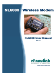
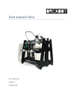
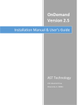
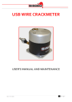
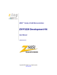
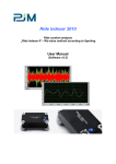
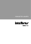
NL900S
900MHz Spread Spectrum
Wireless Transceiver
User’s Manual
Version 1.7
7610 MIRAMAR ROAD
SAN DIEGO, CA 92126 (800) 233-1728
www.rfneulink.com
[email protected]
Document Information
Copyright Information
Copyright © 2011 RF NEULINK All rights reserved.
The information contained in this manual and the accompanying software programs are copyrighted and all rights
are reserved by RF NEULINK. RF NEULINK reserves the right to make periodic modifications of this product
without obligation to notify any person or entity of such revision. Copying, duplicating, selling, or otherwise
distributing any part of this product without the prior consent of an authorized representative of RF NEULINK is
prohibited.
All brands and product names in this publication are registered trademarks or trademarks of their respective holders.
This material is preliminary
Information furnished by RF NEULINK in this specification is believed to be accurate. Devices sold
by RF NEULINK are covered by the warranty and patent indemnification provisions appearing in its
Terms of Sale only. RF NEULINK makes no warranty, express, statutory, and implied or by
description, regarding the information set forth herein. RF NEULINK reserves the right to change
specifications at any time and without notice.
RF NEULINK’s products are intended for use in normal commercial applications. Applications
requiring extended temperature range or unusual environmental requirements such as military,
medical life-support or life-sustaining equipment are specifically not recommended without
additional testing for such application.
Limited Warranty
For a period of one (1) year from the date of purchase, RF NEULINK warrants the transceiver
against defects in materials and workmanship. RF NEULINK will not honor this warranty (and
this warranty will be automatically void) if there has been any:
(1) Tampering, signs of tampering, or opening the transceiver’s case.
(2) Exposure to water or water vapor. Outside operation requires the NL900S be contained in
a NEMA 4 enclosure or better.
(3) Repair or attempt to repair by anyone other than an RF NEULINK authorized
technician.
This warranty does not cover and RF NEULINK will not be liable for, any damage or failure
caused by misuse, abuse, acts of God, accidents, electrical irregularity, or other causes
beyond RF NEULINK's control, or claim by other than the original purchaser.
NL900S USER MANUAL
2
FCC Information
FCC Notice
WARNING: This device complies with Part 15 of the FCC Rules. Operation is subject to
the following two conditions: (1) This device may not cause harmful interference and
(2) This device must accept any interference received, including interference that may
cause undesired operation.
RF Exposure/Installation Instructions
WARNING: To satisfy FCC RF exposure requirements for mobile transmitting devices,
this equipment must be professionally installed such that the end user is prevented
from replacing the antenna with a non-approved antenna. The end user should also
be prevented from being within 20cm of the antenna during normal use with the
exception of hands, feet, wrists and ankles.
The preceding statement must be included as a CAUTION statement in manuals for
OEM products to alert users on FCC RF Exposure compliance
Caution: Any change or modification not expressly approved by RF NEULINK could void the user’s authority
to operate the equipment.
NL900S USER MANUAL
3
Table of Contents
1.0 Introduction ....................................................................................................... 5
1.1 Why Spreadspectrum.......................................................................................... 5
1.2 Frequency Hopping versus Direct Sequence ...................................................... 6
1.3 RS232 Cable Pinout Definitions .......................................................................... 7
1.4 RJ45 Cable Pinout Definitions............................................................................ 7
1.5 USB Cable Pinout Definitions.............................................................................. 7
1.6 NL900S Configuration Utility Software .............................................................. 11
1.7 Troubleshooting Tips......................................................................................... 12
2.0 Quick Start Trouble Shooting Guide.......................................... 12
3.0 Ethernet Device Bridge Setup Guide ......................................... 14
3.1 Setup................................................................................................................. 14
3.2 Configuration..................................................................................................... 14
3.3 Testing The Link................................................................................................ 15
4.0 Repeater Mode Configuration .................................................... 16
* Before configuring or using the Ethernet interface, please read Section
3.3 Testing The Link
NL900S USER MANUAL
4
1.0 Introduction
The NL900S series transceivers provide highly reliable wireless connectivity for either point-topoint or point-to-multipoint applications. Frequency hopping spread spectrum (FHSS)
technology ensures maximum resistance to multipath fading and robustness in the presence of
interfering signals, while operation in the 900 MHz ISM band allows license-free use in the US
and Canada. The NL900S supports all standard serial data rates for host communications from
1.2 to 115.2 kb/s. On-board data buffering and an error-correcting air protocol provide smooth
data flow and simplify the task of integration with existing applications. Key NL900S features
include:
•
Multipath fading resistant frequency hop- ping
technology with up to 50 frequency channels
(902 to 928 MHz).
•
Selectable 1, 10, 100, 250, 500 or 1000 mW
transmit power with a firmware interlock of
85 mW maximum for 500 kb/s operation.
•
Support for point-to-point or point-tomultipoint applications.
•
Optional AES encryption provides
protection to eavesdropping
•
FCC 15.247 certified for license-free
operation.
•
Nonvolatile memory stores NL900S
configuration when powered off
•
20 mile plus range with omni-directional antennas
(antenna height dependent).
•
Simple serial interface handles data up to 115.2
kb/s
•
Transparent ARQ protocol with data
buffering ensures data integrity
1.1 Why Spread Spectrum?
A radio channel can be very hostile, corrupted by noise, path loss and interfering transmissions
from other radios. Even in an interference-free environment, radio performance faces serious
degradation through a phenomenon known as multipath fading. Multipath fading results when two
or more reflected rays of the transmitted signal arrive at the receiving antenna with opposing phases,
thereby partially or completely canceling the signal. This problem is particularly prevalent in indoor
installations. In the frequency domain, a multipath fade can be described as a frequency-selective
notch that shifts in location and intensity over time as reflections change due to motion of the radio
or objects within its range. At any given time, multipath fades will typically occupy 1% - 2% of the
band. From a probabilistic viewpoint, a conventional radio system faces a 1% - 2% chance of signal
impairment at any given time due to multi- path fading.
Spread spectrum reduces the vulnerability of a radio system to interference from both multipath
fading and jammers by distributing the transmitted signal over a larger region of the frequency
band than would otherwise be necessary to send the information. This allows the signal to be
reconstructed even though part of it may be lost or corrupted in transmission.
NL900S USER MANUAL
5
Narrow-band versus spread-spectrum transmission
Figure 1.1.1
1.2
Frequency Hopping versus Direct Sequence
The two primary approaches to spread spectrum are direct sequence spread spectrum (DSSS)
and frequency hopping spread spectrum (FHSS), either of which can generally be adapted to a
given application. Direct sequence spread spectrum is produced by multiplying the transmitted data
stream by a much faster, noise-like repeating pattern. The ratio by which this modulating pattern
exceeds the bit rate of the base-band data is called the processing gain, and is equal to the
amount of rejection the system affords against narrow-band interference from multipath and
jammers. Transmitting the data signal as usual, but varying the carrier frequency rapidly according
to a pseudo-random pattern over a broad range of channels produces a frequency hopping
spectrum system.
Forms of spread spectrum - direct sequence and frequency hopping
Figure 1.1.2
NL900S USER MANUAL
6
1.3
RS232 Cable Pinout Definitions
Standard RS232 DB9 Female Connector
Null Modem RS232 DB9 Male Connector
(Black DB9 Female/Female Cable)
(Gray DB9 Female/Male Cable)
Pin
1
2
3
4
5
6
7
8
9
Description
DCD
RxD
TxD
DTR
GND
DSR
RTS
CTS
RI
1.4
RJ45 Cable Pinout Definitions
1.5
USB Cable Pinout Definitions
NL900S USER MANUAL
7
1.6
NL900S Configuration Utility Software
The software CD included with your NL900S units provides a utility for changing the settings on
each unit.
1.6.1 Installation
1. Remove the contents of the box - Contents should include:
a. NL900S unit
b. This Quick Start Guide
c. Installation CD for the Radio Configuration Suite (RCS) Lite
2. Install the software on a Windows (2000, XP, Vista, or Window 7) PC a. Insert the installation CD.
b. The CD is equipped with Autorun, which should launch the installation program
automatically. If you do not have Autorun enabled, or if the installation program does
not launch automatically:
i. Go to “My Computer” and double-click on the CD/DVD drive containing the
installation media.
ii. If this does not launch the Setup program, browse the CD and locate the
‘RCSLite#.#.#Setup.exe’ file and double-click it.
c. Follow the setup wizard’s on screen instructions until installation is complete.
3. Plug in the NL900S radio and install the drivers –
a. Connect a compatible power supply to the NL900S radio.
b. Wait until the radio has booted up completely (Solid green “PWR” light, and a slow
flashing green “ACT” light).
c. Note: If this is the first time the radio modem has been configured, only the USB
port can be used for configuration. Because no serial RS232 or Ethernet port has
been enabled or configured yet. The serial port will be active once you have
configured the radio modem for a RS232 serial port with the Wizard. This is also
applicable for the Ethernet port.
The USB port is always accessible for programming the NL900S, regardless of
whether the radio modem was configured for Serial or Ethernet.
d. Connect the radio to your PC with a USB or Serial (DB9) cable (Recommended). If using
a USB cable follow the instructions below, otherwise go to Step (4. Configure the
NL900S radio –)
Note: When using USB, even after the drivers are installed the COM Port will
not become available until the radio is plugged in.
i. To install the USB virtual COM Port Drivers using the Setup Utility
NL900S USER MANUAL
8
1. Insert the installation disk and execute "WIN_CDM20802_Setup". Which
should be located at [CD Drive letter e.g. (D:)]\Drivers\Win32
ii. To install the USB virtual COM Port Drivers Manually (XP)
1. After a few moments, a message should appear that your computer has
“found new hardware” and the “Found New Hardware Wizard” should appear.
When asked “Can Windows connect to Windows Update to search for software?”
select “No, not this time”, and click the “Next >” button.
2. Make sure that the installation CDs is in the CD/DVD drive.
3. Select “Install the software automatically (Recommended)”, and click “Next >”
4. The drivers should be automatically located and installed. Click “Finish”
5. You may be presented with a second “Found New Hardware Wizard”, if so,
repeat steps 1-4 (in this section).
d. It is important to identify which virtual COM Port was installed so that when prompted
by the configuration wizard you will know which Comport to select. Open the Device
Manager by clicking on “Start”, “Run”, enter “devmgmt.msc” in the “Open:” field, and
then click the “OK” button. Expand the [+]“Ports (COM & LPT)” section. The USB
COM Port should be labeled “USB Serial Port (COM#)”. This COM# will be the one
you will use - when configuring the radio via USB. It is also possible to configure the
radio via a DB9 serial cable to a particular COM#.
Note: It may be necessary to reboot your computer in order for the newly installed
COM Port to finish installing and show up in the Device Manager.
4. Configure the NL900S radio
a. Launch the configuration wizard to configure the radio by either double-clicking the
“NL900S RCS Lite” desktop icon, or by launching it from the programs menu; (Accessed by
clicking on the “Start” button) under “All Programs”, “NL900S RCS Lite”, “NL900S RCS Lite”
b. If you wish to create a Radio database at the default path, simply go to the next step
(c), otherwise press the “New” button on the initial wizard screen (Figure 1) and select the
location in which you wish to create the new radio database.
c. To login to the specified database, press the “Next >>” button (next page).
NL900S USER MANUAL
9
Figure 2
d. You will be presented with a login window. The default passwords are noted below
(Figure 3). It is highly recommended that you change your passwords immediately
and that you setup your recovery info.
Note: You can change your password, and edit your recovery info by selecting “Change
wizard settings.” when asked, “What task would you like to perform?” in the Master
Wizard. This login information will pertain only to the radio database (*.rdb) that was
selected.
Default Usernames/Passwords
User Level Access Username:
user Password: user
Administrative Level Access
Username: admin
Password: admin
Figure 3
User Level Access – User Level Access allows you to perform many of the basic tasks for
configuring a radio. Such as:
NL900S USER MANUAL
10
•
•
•
•
•
•
Creating a New Configuration
Opening a Radio Database
Loading a Configuration
Programming a Radio
Basic Configuration of a Radio (Enough access for a majority of
configuration tasks)
Change User Level login information
Administrative Level Access – Administrative Level Access allows you to perform all the
basic tasks listed above plus advanced tasks. Such as:
1. Access to the Expert Configuration Mode
• Read a radio’s configuration
2. Changing the advanced settings of the radio
• Transmit Power
• OTA Data Rate
• Encryption
• Compression
• Changing the Radio’s configuration password
• Air Ack Requirements
•
3. Change both Administrative Level and User Level login information
Note: Settings made while in Expert or Advanced Configuration Modes could render the Radio unusable. Proceed at
your own risk!
e.
Follow the wizard’s on screen instructions, and when asked, “How is your radio
connected to this PC?” select the appropriate COM Port from the list. If the radio is set
to defaults (as it comes configured from the factory), the appropriate baud rate should
be “115200”. Proceed through the wizard.
f. Verify the settings in the Summary screen, and proceed to the “Program your radio.”
page, and when ready, press the “PROGRAM RADIO” button.
1.7
Troubleshooting Tips
1. After attempting to install the USB drivers, I get an error, or my USB COM port does not
show up in the dropdown list of the Radio Configuration Suitea. If the COM Port simply does not show up in the list. Close the configuration program and
re-open it.
b. If the above does not resolve the issue then reboot your PC.
c. If the issue is still not resolved, it may be necessary to re-install the driver. You must first uninstall the old/corrupt driver; you can accomplish this by:
• Click on “Start”, then “Run”, type “devmgmt.msc” into the “Open:” box, and click “OK”.
(This should open the Device Manager)
• In the Device Manager find the device section with the yellow question mark. It
NL900S USER MANUAL
11
should be labeled something like “FT232R USB UART” and/or “USB Serial Port”.
Highlight each one individually (if more than one exists), then browse to the “Action” menu
and select “Uninstall”. Do this until all Items with yellow question marks labeled as noted
above are gone.
• Browse to the “Action” menu, and select “Scan for hardware changes”.
• Now, follow the instruction in section 3 of the “Quick Start Guide”.
LED Functionality
LED Definitions Below
LED# - Color
Normal Operation
4 - Green
MCU Activity [ Solid = Radio Base OS booting, Blinking = NL900S software loaded
and running ]
4 - Red
MCU Error [ Solid only, indicates unrecoverable error, power cycle needed ]
3 - Green
Serial and/or USB data is being sent [ to the host computer ]
3 - Red
Serial and/or USB data is being received [ from the host computer ]
1 - Green
Radio RX/Sync [ data or base station sync received ]
2 - Red
Radio TX [ transmitter active ]
Radio RX (Receive Data)
2 - Green
2.0 Quick Start Trouble Shooting Guide
The following is a list of the most important fields of the radios programming. .
1
Network I.D. All radios on the same network must have the same ID number. The
choices are 1-255.
NL900S USER MANUAL
12
2
3
4
5
6
Radio I.D. All radios on the same network must have a unique address. If the radio is a
“MASTER”, the address MUST be “0”. All other radios on that network must have an
address between 1 and 254.
Role. The choices are “Master” or “Slave. There can be only one master per network.
All others in that network must be slaves.
Destination Radio I.D. Place the unique address of the radio to be communicated with
in this field. The choices are 0-254. An address of 255 in all radios, including the
master will cause the slaves and the master all to talk to each other in broad cast
mode.
Destination Network I.D. This field must have the same ID as all radios on the same
network.
Encryption. Encryption is turned on by default and it is important to note that the
encryption code will be the same on all radios programmed from the same Radio Data
Base, (Radio.rdb). Radios programmed from a different RDB will have different codes
and will not talk to radios that were programmed from the first RDB. You must either
turn off encryption or manually generate a new code and program that code into each
radio. All other applicable fields are selected and filled in automatically when
programming is done. These field values can be changed but only advanced users
should consider changing the information in these fields.
See the example in the figure below.
The 6 fields of special attention are numbered in red.
NL900S USER MANUAL
13
3.0 Ethernet Device Bridge Setup Guide
This mode is only designed to bridge a single low activity remote IP device to its parent. It can not
be used to bridge two networks. Please keep in mind that remote device's OS and installed
applications can generate massive amounts of unwanted network traffic through services, auto
update, "call home" features, etc. If these are not minimized the link can become saturated and
unusable.
3.1
Setup
You will need two PCs (Turn off all unnecessary services and programs e.g. Windows Update,
Adobe Installer, Firefox updater, etc.), two Ethernet crossover cables, two radios (Master and
Slave configured for Ethernet bridging). We recommend using the wizard to help insure proper
configuration. Initially you will need to leave the Radio/PCs disconnected until instructed to do
otherwise.
3.2
•
•
•
•
•
•
•
•
•
Configuration
It is recommended to set Radio TX power to 10 mW if the radios are in close proximity.
Bridge Mode should be enabled on both the Master and Salve.
Master ID should be 0.
Ethernet Crossover Cable must be used when not using a hub or switch.
• Radio Link LED must be solid on, for both Master and slave for communications to occur.
• Sequence of events to get a link light on the Master when configured as an Ethernet device
bridge:
• Radio module must generate Slave Linked message to NIOS
• Master sends authorization request to slave, slave sends response
• If the Slave's response contains the same Network ID and Radio as the Master's
configured destination, the LED is toggled on.
• Sequence of events to get a link light on the Slave when configured as an Ethernet device
bridge:
• Radio module must generate a joined network message.
If the radio module generates a slave left network message, Link LED is toggled off.
We recommend using static IP’s for both radios and all remote devices, and to leave the
gateway field blank.
DHCP is not supported on the remote slave radio or attached device. This is due to the fact,
the remote radio or device can not communicate with the DHCP server on the other side of the
link without the Ethernet being configured dilemma.
The USB and Serial Ports are ignored when Ethernet device bridging is enabled.
If you are seeing a massive amount of data going over the link, indicated by Ethernet activity
and Tx/Rx activity lights, you have a program or service on one or both of the connected
devices that is producing unwanted traffic; this could render the link unusable.
NL900S USER MANUAL
14
Cross Over
Cross Over
PC2
PC1
Master
3.3
Slave
Testing the link
In order to test the Ethernet device link effectively, you should test each part of the link in
sequence. Without a reliable link at the radio level (Indicated by a solid link light), especially due to
the data requirements of TCP/IP, the link will be unusable. Due to the fact that there are several
encapsulating frames, and to that packets of a certain length are broken up and reassembled, the
hopping times required by the radio module, and the Ack/Nack connection nature of TCP/IP, the
throughput of the link can be limited.
1. Configure both the Master and Slave radios for Ethernet Device Bridging (Wizard). Make
sure that each radio has the other as the destination of the Ethernet Device Bridge.
2. Power on both radio modems and wait a MINIMUM of 20 SECONDS for each radio to boot
up and establish a radio link.
3. Verify that the link light is on solid for both Master and Slave radios.
4. Only connect the Ethernet Crossover cable between PC1 and the Master radio at this time.
DO NOT connect the Ethernet Crossover cable between PC2 and the Slave radio.
5. Ping the Master's assigned IP address using PC1.
6. If that is successful, ping the Slave Radio's assigned IP address. Check for blinking
Ethernet Activity LED and Radio TX LED (Red).
7. Now connect PC2 using a Ethernet Crossover cable to the remote Slave.
8. Ping the Slave's assigned IP address from PC2. If successful, ping the Master's assigned IP
address from PC2.
9. Now that pings are traveling both directions, you may attempt to ping PC2 from PC1 and
vice versa. Ping times could be slower since all broadcast traffic on the network is being
transmitted across the bridge (arp packets, etc).
Once you are able to ping in both directions, now you can test connectivity at the application level.
NL900S USER MANUAL
15
4.0
Repeater Mode Configuration – Serial Mode Only
The following describes configuring a NL900S to operate as a repeater. “This feature set is
supported in serial mode only”.
First, program the NL900S Radio Modem as you normally would as a Master. Change only the
Destination Radio ID address to 255. This will cause the master to repeat (retransmit) any
message it hears on its assigned Network ID to all slaves on the same network.
Next, program two Slave Radio Modems as you would normally. Again change only the
Destination Radio ID. Program the Destination Radio ID of each Slave to talk directly to the other.
(Slave 1 talks to Slave 2 and vice versa) This will allow the slaves to talk to each other through the
Master/ Repeater and there by extending the usable range.
Since the Master/ Repeater will repeat any message it hears on its Network ID, multiple Slaves can
be employed. (Slave 1 talks to 2 and vice versa, Slave 3 talks to 4 and vice versa and so on up to
127 pairs or a total of 254 slaves.
Repeater Radio
Network 1
Destination
Address 255
Slave Radio 1
Slave Radio 2
Network 1
Network 1
Destination
Address 2
Destination
Address 1
NL900S USER MANUAL
16
Slave Radio 1
Slave Radio 2
Network 1
Network 1
Destination
Address 2
Destination
Address 1
Repeater Radio
Network 1
Destination
Address 255
Slave Radio 3
Slave Radio 4
Network 1
Network 1
Destination
Address 4
Destination
Address 3
NL900S USER MANUAL
17