Transcript
Specifications
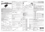
INDUCTIVE PROXIMITY SENSOR
CYLINDRICAL TYPE DC 3WIRE
A
N
U
A
L
Model
Thank you very much for selecting Autonics products.
For your safety, please read the following before using.
Caution for your safety
※Please keep these instructions and review them before using this unit.
※Please observe the cautions that follow;
Warning Serious injury may result if instructions are not followed.
Caution Product may be damaged, or injury may result if instructions are not followed.
※The following is an explanation of the symbols used in the operation manual.
Caution: Injury or danger may occur under special conditions.
Sensing distance
Hysteresis
Standard sensing
target
Setting distance
Power supply
(Operating voltage)
Current consumption
Response frequency
Residual voltage
Affection by Temp.
Control output
Insulation resistance
Dielectric strength
Vibration
Shock
Indicator
Environment
M
Caution
PR12-4DN
PR12-4DP
PR12-4DN2
PR12-4DP2
PRS12-4DN
PRS12-4DP
PRS12-4DN2
PRS12-4DP2
PRW12-4DN
PRW12-4DP
PRW12-4DN2
PRW12-4DP2
PRL12-4DN
PRL12-4DP
PR18-5DN
PR18-5DP
PR18-5DN2
PR18-5DP2
PRL18-5DN
PRL18-5DP
PRL18-5DN2
PRL18-5DP2
PRW18-5DN
PRW18-5DP
PRW18-5DN2
PRW18-5DP2
PRWL18-5DN
PRWL18-5DP
PRWL18-5DN2
PRWL18-5DP2
PR18-8DN
PR18-8DP
PR18-8DN2
PR18-8DP2
PRL18-8DN
PRL18-8DP
PRL18-8DN2
PRL18-8DP2
PRW18-8DN
PRW18-8DP
PRW18-8DN2
PRW18-8DP2
PRWL18-8DN
PRWL18-8DP
PRWL18-8DN2
PRWL18-8DP2
1.5mm
2mm
Max. 10% of sensing distance
2mm
4mm
5mm
8mm
10mm
15mm
8×8×1mm(Iron)
12×12×1mm(Iron)
18×18×1mm(Iron)
25×25×1mm(Iron)
30×30×1mm(Iron)
45×45×1mm(Iron)
0 to 7mm
0 to 10.5mm
400Hz
200Hz
0 to 1.05mm
0 to 1.4mm
0 to 2.8mm
0 to 3.5mm
0 to 5.6mm
12-24VDC
(10-30VDC)
Max. 10mA
1.5kHz
1kHz
1.5kHz
500Hz
500Hz
350Hz
Max. 2.0V
Max. 1.5V
Within ±10℃ max. of sensing distance at 20℃ in temperature range of -25 ~70℃(PR 08 Series: Max. ±20%)
Max. 200mA
Min. 50MΩ(at 500VDC megger)
1,500VAC 50/60Hz for 1minute
1mm amplitude at frequency of 10 to 55Hz in each of X, Y, Z directions for 2 hours
500m/s2(50G) X, Y, Z directions for 3 times
Operating indicator(Red LED)
-25 to 70℃, Storage: -30 to 80℃
Ambient
humidity
35 to 95%RH, Storage: 35 to 95%RH
Unit weight
5
Type
M8, M12, M18, M30
Sensing distance
Dimension
Body size
Connection
Shape
Item
NPN N.O.(Normally Open)
NPN N.C.(Normally Closed)
PNP N.O.(Normally Open)
PNP N.C.(Normally Closed)
Number
Standard sensing distance(Unit: mm)
Number
Diameter of head(mm)
No mark
S
L
Standard
Short body
Long body
No mark
W
DC 3 wire, cable outgoing type
DC 3 wire, cable outgoing connector type
R
Cylindrical type
P
Inductive proximity sensor
M8
M12
Flush
M18
M30
M8
Main circuit
10kΩ
Black
+V
Load
Normally Open
Normally Closed
Presence
Nothing
Presence
Nothing
Operation
Return
Operation
Return
(Black-Blue)
H
L
H
L
Indicator
(LED)
ON
OFF
ON
OFF
Normally Open
Normally Closed
Presence
Nothing
Presence
Nothing
Operation
Return
Operation
Return
(Black-Blue)
H
L
H
L
Indicator
(LED)
ON
OFF
ON
OFF
Sensing
target
Load
(Brown-Black)
Output voltage
Blue
0V
Brown
+V
Black
10kΩ
Blue
D
Sensing
target
Load
(Black-Blue)
Output voltage
Load
0V
※ The above specifications are subject to change without notice.
PR 08-1.5D
PR 08-2D
PR 12-2D
PR 12-4D
PR 18-5D
PRW 18-5D
PR 18-8D
PRW 18-8D
PR 30-10D
PRW 30-10D
PR 30-15D
PRW 30-15D
9
16
0
8
4.5
12
12
24
8
24
6
24
12
24
0
12
6
18
24
36
11
36
12
36
30
36
0
18
15
27
48
54
14
54
24
54
60
60
0
30
30
45
90
90
15
90
45
90
M12
Nonflush
M18
M30
Moving
direction
J
H
A
(70% of Sn)
(b)
(a)
Model
Head
M12×1
A
A
B
C
D
E
F
G
H
J
M8×1
M8×1
M8×1
M8×1
M12×1
M12×1
M12×1
M12×1
M18×1
M18×1
M18×1
M18×1
M30×1.5
M30×1.5
M30×1.5
M30×1.5
M8×1
M8×1
M8×1
M8×1
M12×1
M12×1
M12×1
M12×1
M18×1
M18×1
M18×1
M18×1
M30×1.5
M30×1.5
M30×1.5
M30×1.5
30
40
30
40
46
39
46
58.5
47.5
80.5
47.5
80.5
58
80
58
80
30
40
30
40
46
39
46
58.5
47
80
47
80
58
80
58
80
30
40
30
40
31.5
24.5
31.5
44
29.5
62
29.5
62
38
60
38
60
30
40
30
40
31.5
24.5
31.5
37
29
62
29
62
38
60
38
60
4
4
4
4
4
4
4
4
4
4
4
4
5
5
5
5
4
4
4
4
4
4
4
4
4
4
4
4
5
5
5
5
4
4
4
4
7
7
7
7
10
10
10
10
10
10
10
10
2,000
2,000
300
300
2,000
2,000
300
2,000
2,000
2,000
300
300
2,000
2,000
300
300
2,000
2,000
300
300
2,000
2,000
300
2,000
2,000
2,000
300
300
2,000
2,000
300
300
3.5
3.5
4
4
4
4
4
4
5
5
5
5
5
5
5
5
3.5
3.5
4
4
4
4
4
4
5
5
5
5
5
5
5
5
13
13
13
13
17
17
17
17
24
24
24
24
35
35
35
35
13
13
13
13
17
17
17
17
24
24
24
24
35
35
35
35
15
15
15
15
21
21
21
21
29
29
29
29
42
42
42
42
15
15
15
15
21
21
21
21
29
29
29
29
42
42
42
42
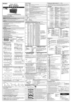
Front
NPN
Load
0V
2 1
3 4
Brown
Blue
Mounting
bracket
[Picture 2]
Rear
Torque
Torque
40kgf· cm
(3.92N·m)
90kgf· cm
(8.82N·m)
PR08 Flush
Series Non-flush
7mm
PR12 Flush
Series Non-flush
13mm 65kgf· cm
(6.37N·m)
7mm
PR18 Flush
Series Non-flush
-
PR30 Flush
Series Non-flush
26mm 500kgf· cm
12mm (49N·m)
5mm
-
120kgf· cm
(11.76N·m)
150kgf· cm
(14.7N·m)
800kgf· cm
(78.4N·m)
[Table 1]
※It may cause malfunction if above instructions are not followed.
Major products
+V
Black
Washer
Strength Front
Size
Note1) Allowable tightening torque of a nut may be different by the distance from the head. For allowable tightening torque and the range of front and rear
parts, refer to [Table 1] and above [Picture 1] respectively. The rear part includes a nut on the head side(see above [Picture 1]). Please apply
a tightening torque of the front part when the nut on the front is located in the front part.
Note2) The allowable tightening torque denotes a torque value when using a provided washer as above [Picture 2].
5. Please check the voltage changes of power source in order not to excess the rated power input.
6. Do not use this unit during transient time(80ms) after apply power.
7. It might result in damage to this product, if use automatic transformer. So please use insulated transformer.
8. Please make wire as short as possible in order to avoid noise.
9. Be sure to use cable as indicated specification on this product. If wrong cable or bended cable is used, it shall not maintain the water
proof.
10. It is possible to extend cable with over 0.3mm2 and max. 200m.
11. If the target is plated, the operating distance can be changed by the plating material.
12. It may result in malfunction by metal particle on product.
13. If there are machines(motor, welding etc), which occurs big surge around this unit, please install the varistor or absorber to source of surge, even though
there is built-in surge absorber in this unit.
14. If connecting the load with big inrush current(DC type bulb) to this unit, the big inrush current will flow because the initial resistance is low. If the current
flows, the resistance of load will be bigger, then it will return to standard current. In this case, proximity sensor might be damaged by inrush current. If you
use DC type bulb, please connect extra relay or resistance in order to protect proximity sensor.
15. If making a transceiver close to proximity sensor or wire connection, it may cause malfunction.
PNP
+V
Rear
[Picture 1]
Connections
Blue
Setting distance(Sa)
= Sensing distance(Sn) × 70%
Ex)PR30-10DN(See ordering information)
Setting distance(Sa) = 10mm × 0.7 = 7mm
※G
D
2 1
3 4 Black
●
※F
※'F' type standard: Cable outgoing type/2,000mm, Cable outgoing connector type/300mm
※'G' type: ø3.5, 3 cores(Conductor cross section: 0.2mm2, Insulator diameter: ø1) and ø4, 3 cores/ø5, 3 cores(Conductor cross section: 0.3mm2,
Insulator diameter: ø1.25)
Connector
Sa Sn
Sensing distance can be changed by the shape, size or material of the target.
Therefore please check the sensing distance like (a), then pass the target within
range of setting distance(Sa).
Caution for using
A
E
Brown
●
Target
1. This equipment shall not be used outdoors or beyond specified temperature range.
2. Do not apply over tensile strength of cord. (ø3.5: 25N max. ø4: 30N max., ø5: 50N max.)
3. Do not use the same conduit with cord of this unit and electric power line or power line.
4. Do not put overload to tighten nut, please use the supplied washer for tightening.
C
※G
PR
PRL
PRW
PRWL
PR
PRS
PRW
PRL
PR
PRL
PRW
PRWL
PR
PRL
PRW
PRWL
PR
PRL
PRW
PRWL
PR
PRS
PRW
PRL
PR
PRL
PRW
PRWL
PR
PRL
PRW
PRWL
ℓ
Nut & Washer
M12×1
B
Type
Control output diagram & Load operating
Brown
ℓ
Moving
direction
PR: Approx. 170g
PRL: Approx. 210g
PRW: Approx. 122g
PRWL: Approx. 158g
※G
※F
E
n
ℓ
Target
C
A
D
DN
DN2
DP
DP2
ød
Item
A
B
ℓ
ød
m
n
※F
B
※F
※G
Flush
Nonflush
Standard cable
Oil resistant cable
Option
◎Influence by surrounding metals
When sensors are mounted on metallic panel, it is required to protect the sensors from being affected by any metallic object except target.
Therefore, be sure to provide a minimum distance as below chart.
Sn:Sensing distance
B
No mark
V
S
B
{ Sa:Setting distance
M8, M12, M18, M30
B
Parallel
A
Model
(Unit: mm)
C
Output
Main circuit
PR: Approx. 110g
PRL: Approx. 130g
PRW: Approx. 58g
PRWL: Approx. 78g
Cable outgoing connector type
D
Cable type
PNP
Output
PR: Approx. 72g
PRS: Approx. 70g
PRW: Approx. 42g
PRL: Approx. 76g
C
●
Setting distance
Cable outgoing type
V
DN
Face to Face
※Environment resistance is rated at no freezing or condensation.
Ordering information
P R W L 18
●
m
Approval
PR: Approx. 52g
PRL: Approx. 54g
PRW: Approx. 32g
PRWL: Approx. 34g
◎Mutual-interference
When several proximity sensors are mounted closely, malfunction of sensor may be caused due to mutual interference. Therefore, be
sure to provide a minimum distance between the two sensors with referring to the chart below.
(Unit: mm)
Dimensions
1. Do not use this unit in place where there are flammable, explosive gas, chemical or strong alkalis, acids.
It may cause a fire or explosion.
2. Do not impact on this unit.
It may result in malfunction or damage to the product.
3. Do not apply AC power and observe the rated specification.
It may result in serious damage to the product.
NPN
Output
PR30-15DN
PR30-15DP
PR30-15DN2
PR30-15DP2
PRL30-15DN
PRL30-15DP
PRL30-15DN2
PRL30-15DP2
PRW30-15DN
PRW30-15DP
PRW30-15DN2
PRW30-15DP2
PRW30-15DN-V
PRW30-15DP-V
PRWL30-15DN
PRWL30-15DP
PRWL30-15DN2
PRWL30-15DP2
Surge protection, Reverse polarity proteciton, Overload & short circuit protection
IP67(IEC Standards)
Case/Nut: Nikel plated Brass, Washer: Nikel plated Iron, Sensing surface: Heat-resistant ABS,
Standard cable(Black): Polyvinyl chloride(PVC), Oil resistant cable(Gray): Oil resistant Polyvinyl chloride(PVC)
Materials
1. In case of using this unit with machinery(Ex: nuclear power control, medical equipment, ship, vehicle,
train, airplane, combustion apparatus, safety device, crime/disaster prevention equipment, etc) which
may cause damages to human life or property, it is required to install fail-safe device.
It may cause a fire, human injury or damage to property.
PR12-2DN
PR12-2DP
PR12-2DN2
PR12-2DP2
PRS12-2DN
PRS12-2DP
PRS12-2DN2
PRS12-2DP2
PRW12-2DN
PRW12-2DP
PRW12-2DN2
PRW12-2DP2
PRL12-2DN
PRL12-2DP
PR08-2DN
PR08-2DP
PR08-2DN2
PR08-2DP2
PRL08-2DN
PRL08-2DP
PRL08-2DN2
PRL08-2DP2
PRW08-2DN
PRW08-2DP
PRW08-2DN2
PRW08-2DP2
PRW08-2DN-V
PRW08-2DP-V
PRWL08-2DN
PRWL08-2DP
PRWL08-2DN2
PRWL08-2DP2
Ambient
temperature
Protection circuit
Protection
Warning
Mutual-interference & Influence by surrounding metals
PR30-10DN
PR30-10DP
PR30-10DN2
PR30-10DP2
PRL30-10DN
PRL30-10DP
PRL30-10DN2
PRL30-10DP2
PRW30-10DN
PRW30-10DP
PRW30-10DN2
PRW30-10DP2
PRW30-10DN-V
PRW30-10DP-V
PRWL30-10DN
PRWL30-10DP
PRWL30-10DN2
PRWL30-10DP2
PR08-1.5DN
PR08-1.5DP
PR08-1.5DN2
PR08-1.5DP2
PRL08-1.5DN
PRL08-1.5DP
PRL08-1.5DN2
PRL08-1.5DP2
PRW08-1.5DN
PRW08-1.5DP
PRW08-1.5DN2
PRW08-1.5DP2
PRW08-1.5DN-V
PRW08-1.5DP-V
PRWL08-1.5DN
PRWL08-1.5DP
PRWL08-1.5DN2
PRWL08-1.5DP2
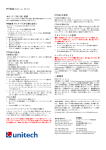
Load
0V
Proximity sensors
Area sensors
Photoelectric sensors
Fiber optic sensors
Door/Door side sensors
Sensor controllers
Graphic/Logic panels
Temperature controllers
Tachometer/Pulse(Rate) meters
Temperature/Humidity transducers
Switching power supplies
Stepping motors/drivers/motion controllers
Field network devices
Laser marking system(CO₂ , Nd:YAG)
Laser welding/soldering system
Counters
Timers
Display units
Panel meters
Pressure sensors
Rotary encoders
Power controllers
http://www.autonics.com
Satisfiable Partner For Factory Automation
HEAD QUARTERS :
41-5. Yongdang-dong, Yangsan-si, Gyeongnam, 626-847,
Korea
OVERSEAS SALES :
Bldg. 402 3rd FL., Bucheon Techno Park, 193, Yakdae-dong,
Wonmi-gu, Bucheon-si, Gyeonggi-do, 420-734, Korea
TEL : 82-32-610-2730 / FAX : 82-32-329-0728
E-mail : [email protected]
The proposal of a product improvement and
development: [email protected]
EP-KE-07-0360J