1
PRIMER TRAINER
EXTENDED MONITOR
OPERATING SYSTEM
USER’S MANUAL
Revision 2.1
Copyright 1989-1992 EMAC, Inc.
All Rights Reserved.
DISCLAIMER
EMAC has made every attempt to ensure that the information in this document is accurate
and complete. However, EMAC assumes no liability for any damages that result from use
of this manual or the equipment that it documents. EMAC reserves the right to make
changes at any time.
MOS AND EMOS
REVISION HISTORY
EMOS VERSION 1.6 AND MOS VERSION 2.3
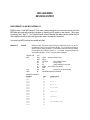
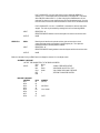
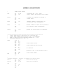
EMOS version 1.6 and MOS version 2.3 both have a feature that allows you to execute a service call in the
MOS data entry mode without writing a program or changing the PC register or user memory. This is done
by pressing "func." then "2". The C register should first be loaded with the desired service number and the
other registers should be loaded with appropriate values, as needed by the service.
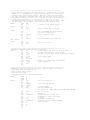
Also seven new MOS services were added as follows:
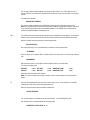
SERVICE 1A
LEDSTR
LED String output; This service routine allows you to individually turn off, or on, any of
the segments on one or more of the numeric displays. The HL register pair will point to
section of data for display bit patterns. The bit patterns stored here control the displays
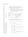
the same as the service LEDOUT (service 11). For example, the following program will
send a pattern displays 4, 3 and 2 , leaving the others unchanged.
LEDSTR EQU
MOS
loop:
bitpat:
1AH
EQU
ORG
Mvi
mvi
mvi
lxi
call
jmp
db
1000H ; address of MOS services
0ff01h
c,LEDSTR
; select LEDSTR service
e,3
; change 3 digits
d,4
; starting at display 4, going right
h,bitpat ; point to table of bit patterns
MOS
loop
; loop here so we can see displays
00010000b,00000100b,10000000b
MACHINE LANGUAGE
ADDRESS
FF01
FF02
FF03
FF04
FF05
FF06
FF07
FF08
FF09
FF0A
FF0B
FF0C
FF0D
FF0E
FF0F
FF10
FF11
FF12
DATA
0E
1A
1E
03
16
04
21
10
FF
CD
00
10
C3
03
FF
10
04
80
INSTRUCTION
MVI C,1A
MVI E,3
MVI D,4
LXI H,FF10
CALL 1000
JMP FF03
BIT PATTERN DATA
INPUT
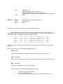
SERVICE 1B
OUTPUT
REGISTER C: 1A
REGISTER E: Number of displays to change ( 1 to 6)
REGISTER D: Starting display (numbered 5-0 from left to right).
REGISTER PAIR HL: Address of string of bit pattern data to be shown on the displays
NONE
DDATA
INPUT
OUTPUT
Display the hex byte in E on the DATA/OP displays
REGISTER C: 1B
NONE
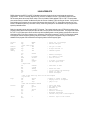
The remaining five new services are used to support the EPROM programmer board.
EMAC's EPROM programmer (E020-8) allows you to program EPROMs of a variety of types and voltages. The
smallest EPROM supported is a 2764 ( 8K x 8 ) and largest EPROM supported is 27512 ( 64K x 8 ). Each EPROM type is given
an identification number. The 6 EPROM type numbers supported are as follows:
TYPE
TYPE
TYPE
TYPE
TYPE
TYPE
#1
#2
#3
#4
#5
#6
27512
27256
27128
27128
2764
2764
(
(
(
(
(
(
64K
32K
16K
16K
8K
8K
x
x
x
x
x
x
8
8
8
8
8
8
)
)
)
)
)
)
EPROM
EPROM
EPROM
EPROM
EPROM
EPROM
WHICH
WHICH
WHICH
WHICH
WHICH
WHICH
PROGRAMS
PROGRAMS
PROGRAMS
PROGRAMS
PROGRAMS
PROGRAMS
AT
AT
AT
AT
AT
AT
12.5
12.5
12.5
21.0
12.5
21.0
VOLTS.
VOLTS.
VOLTS.
VOLTS.
VOLTS.
VOLTS.
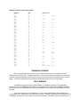
If an illegal type number is passed to one of the following services, the A register will return the value 4, with other registers
unaffected.
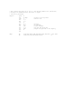
There are four MOS services which support EMAC's EPROM programmer.
READ (service 1C)
Copies a number of bytes starting at an EPROM memory address and stores them in system memory.
VERIFY (service 1D)
VERIFY determines whether the data in the EPROM in the programmer matches a range of data in system memory.
BURN
(service 1E)
This writes a number of bytes from system memory to EPROM.
The above commands require that you load the 8085 registers as follows:
H
L
High order byte of system memory address
High order byte of EPROM address
(NOTE: The low order bytes of the system memory and EPROM addresses default to 0)
DE
B
C
Number of bytes
EPROM type ( as in the table above )
Service number
When VERIFY or BURN, have finished executing with no errors, the A register will be 0 and the other registers(except
the flag register) will be unaffected. If A is not 0, an error has occurred. and the registers will be returned with the following
information.
BC
H
Address that error occurred in system memory
Value of data at address BC in system memory
DE
L
Address that error occurred in the EPROM in the programmer
Value of data at address DE in the EPROM in the programmer
ERASECHK (service 1F)
ERASECHK tells whether an EPROM is erased. This command requires you to load the registers as follows:
DE
Starting address from which to examine EPROM. It examines from this address down to 0.
B
EPROM type ( as in the table above )
C
Service number 1Fh
The A register will be returned with 0 if the EPROM is erased.
ZAP (service 20)
ZAP allows you to put your own application program into a 32k EPROM. BURN also allows this, but ZAP will
automatically examine the EPROM to see if it is erased, put in the initialization and MOS services code and verify that the data
was written correctly. This command requires you to load the registers as follows:
H
High byte of starting address of user program (low byte defaults to 01)
DE
Number of bytes in program (this should be no bigger than 50FEH)
C
Service number 20h
If ZAP has finished executing with no errors, the A register will be 0 and the other registers (except the flag register) will be
unaffected. If an error has occured, the A register will indicate the following:
A=1 Error during EPROM write (registers returned with same values as BURN error)
A=2 Error during verification (registers returned with same values as VERIFY error)
A=3 EPROM not erased (registers returned with same values as ERASECHK error)
To make an EPROM-based application:
1)
Load and test your program. To make it easier to relocate your program to 2F01h, you should start at address XF01h,
where X denotes a hex digit which would result in a valid RAM address. Address FF01h could be used, for example.
2)
Rewrite the program to execute at address 2F01h. If you have an assembler, this will be easy. Otherwise you must
look for all JMP's and CALL's that need to be changed. Remember that if your program refers to data tables, these
should be relocated to EPROM, and all RAM variables should remain at the same address. Also, remember that all
registers, except the stack pointer and program counter must be initialized by the user.
3)
Put a blank 32k EPROM (type 2 EPROM) in the programmer, aligning pin 1 of the chip to pin 1 of the socket, then latch
the socket
4)
Load DE with the length of the program, H with the upper byte of the starting address of the program and C with 20h
(for service 20). Press "func." then "2" to make MOS service call.
5)
Remove power from the trainer and carefully replace its EPROM with the EPROM that was just programmed, making
sure pin 1 of the EPROM goes to pin 1 of the socket. 0J2 must be in position B for a 32k EPROM. Place the unused
EPROM in a static safe area.
6)
Power up your unit and the program should begin to run. If it doesn't work, make sure you have followed these
procedures carefully, especially step 2.
To insure desired results:
When inserting or removing EPROMS, make sure the EPROM burner power LED is off.
When performing an ERASECHK, VERIFY or BURN command make sure the EPROM type was correctly entered.
EMOS has a new menu option which is defined as follows:
Z --> Zap application EPROM
"Z"
The Zap application command allows you to execute the ZAP service from the EMOS prompt
When the command is issued, the Monitor responds with:
STARTING HIGH ADDRESS ...
This is the upper byte of the start address of your program in memory ( the lower byte of the address defaults to 01).
Two hex digits should be typed here.
The monitor then responds with:
NO. OF BYTES..
This is the number of bytes in your program, and can be up to 4 hex digits.
After this, the program will begin to be written to the EPROM and the monitor will respond with appropriate error
messages, if necessary.
EMOS VERSION 1.7
This version fixed a bug in the EPROM programmer drivers.
EMOS VERSION 1.8 AND MOS VERSION 2.4
Service 9 (ADCIN) was speeded up by using a successive approximation algorithm. This new routine is also more accurate at
lower voltages since it now allows for settling time of the A/D circuitry.
The self test mode was modified to do a checksum on the ROM, and also adds a local loopback test of the optional
serial port. At the beginning of the self-test (invoked when the "func." And "1" keys are pressed) a checksum is performed on the
ROM and if an error is detected you will hear a beep and "b.E." will be shown on the right 2 displays indicating "Bad EPROM".
Pressing a key at this point will resume the RAM diagnostics (indicated by "r.d." on the DATA/OP displays). If a bad RAM
location is found, you will hear a beep, the address will be shown on the ADDRESS/REGISTER PAIR displays and "b.r." will
be shown on the right 2 displays. Note that if you don't have a 32K RAM and you get a bad RAM error at 8000, this is not a
valid error. Pressing a key after an error will resume the self-test.
After the RAM diagnostics, the self-test will try to determine whether there is a serial port. If there isn't or if it is not
working, "n.u." will be displayed (indicating No UART). If a serial port is detected, it is examined to see if it is configured for a
local loopback test. It is configured for local loopback when the transmit and receive lines of the serial port are connected to
each other (pins 2 and 3 respectively of the DB9 connector CN2). If it is not configured this way the self-test will work as the
previous versions. This connection allows data transmitted, by the UART to be looped back to the UART, testing both the
transmitter and the receiver.
In this configuration, if the serial port is working, the bytes 00 to FF hex will be transmitted and displayed on the left 2
displays (this will happen quite rapidly at higher baud rates, so if you want to watch it, set JP1 to around 2400 baud). If there is a
problem with the serial communications, you will hear a beep and "b.S." will be shown on the right 2 displays indicating a Bad
Serial port. Pressing a key after this will resume the self test and the UART will be disabled. If the local loopback test runs
without errors "L.L." will be shown on the left 2 displays, the UART will be disabled and the self-test will continue and work the
same as the previous versions. If "L.L." is not displayed and it has been verified that the transmit and receive lines were
connected together, there is a problem with the serial port circuitry.
MOS VERSION 2.5
This includes the improvements to the EPROM programmer drivers from EMOS 1.7 and a new function key which allows the
PRIMER to receive an Intel hex file via the serial port (part number E600-10 or E600-11). To invoke this function press "Func."
then "3". After this, the displays will show "rEC.." indicating that the PRIMER is ready to receive the data. After an ending record
is received, (a record in which the fourth pair of digits following the colon is 01), the PRIMER will return to entry mode. If any
errors occur while receiving the hex file "Err.." will be displayed followed by a hex number. The bits in this number, after it is\
converted to binary indicate the following errors:
BIT#
0
1
2
3
4-7
ERROR
(not used)
checksum error
non-hex character encountered
escape character encountered
(not used)
Pressing a key after the error message will put the PRIMER back into entry mode. Receiving a hex file may be aborted any time
by resetting the PRIMER or by sending an escape character (1Bh) to the PRIMER's serial port. Sending an escape character
will result in an "Err..08".
EMOS VERSION 1.9 AND MOS VERSION 2.6
These change the protocol so that 1 instead of 2 stop bits are transmitted.
EMOS VERSION 2.0 AND MOS VERSION 2.7
This includes four new services and a full menu driven EPROM Programmer which allows you to burn, read, copy and modify
EPROMS from your PC. To invoke the EPROM Programmer menu press ‘Func' then 4'. To use the EPROM Programmer
Software, the PRIMER must be equipped with the EPROM Programmer Board (E020-8) and one of the upgrades (E600-10 or
E600-11).
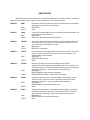
SERVICE 21
DECPNT
LED Decimal Point output. This service allows you to individually turn on or off the 6
decimal points on the LED display. The D register bits 0-5 correspond to digits 0-5. A 0
will turn off the decimal point and a 1 will turn it on.
INPUT
REGISTER C: 21H
REGISTER D: bit pattern to light or unlight appropriate decimal points.
NONE
OUTPUT
SERVICE 22
BIN2BCD
Binary to Binary Coded Decimal. This service converts the 16 bit number in register pair
DE to binary coded decimal with the low nibble in register E being the least significant
digit
INPUT
REGISTER C: 23H
REGISTER PAIR DE: The number to be converted to BCD
REGISTER PAIR DE: The BCD number.
OUTPUT
SERVICE 23
BCD2BIN
Binary Coded Decimal to Binary. This service converts a 4 digit BCD number in register
pair DE to binary.
INPUT
REGISTER C: 24H
REGISTER PAIR DE: 4 digit BCD number
REGISTER PAIR DE: converted number in binary
OUTPUT
SERVICE 24
KPINPUT
Keypad Input. This service allows the user to input up to a 4 digit number from the
keypad. The number will be returned in the DE register pair. The numbers can be
displayed on the LED display by loading D with 1 before the service is called. The LED
display will be turned off if D = 0. The service will not return until the "ENT" key is
pressed. Once ENTER is pressed, the last 4 digits entered will be loaded in DE with the
last digit being the Least significant. If 4 digits are not entered, a 0 will be assumed for
the leading digits.
INPUT
REGISTER C: 24H
REGISTER D: 1 for LED display on, 0 for LED display off.
OUTPUT
REGISTER PAIR DE: 4 digit number from keypad
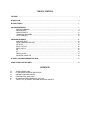
TABLE OF CONTENTS
FEATURES …………………………………………………………………………………………………………………………………. 1
INTRODUCTION …………………………………………………………………………………………………………………………… 2
GETTING STARTED ……………………………………………………………………………………………………………….……… 2
SOFTWARE REFERENCE ……………………………………………………………………………………………………………….. 4
MONITOR COMMANDS ……………………………………………………………………………………………………..... 4
EMOS SERVICES ……………………………………………………………………………………………………………… 12
USING INTERRUPTS ………………………………………………………………………………………………………….. 17
TERMINATING PROGRAMS …………………………………………………………………………………………….…… 18
USE OF RAMDISKS …………………………………………………………………………………………………………… 18
HARDWARE REFERENCE ……………………………………………………………………………………………….……………… 20
HARDWARE RESET ……………………………………………………………………………………………….………….. 20
SERIAL COMMUNICATION PORT …………………………………………………………………………………………... 20
DIP SWITCH ………………………………………………………………………………………………………………..…… 20
DIGITAL OUTPUTS ……………………………………………………………………………………………………………… 20
DIGITAL INPUTS ……………………………………………………………………………………………………………….. 20
D/A …………………………………………………………………………………………………………………………………20
A/D ……………………………………………………………………………………………………………………………….. 21
TIMER/COUNTER …………………………………………………………………………………………………………….... 21
EXPANSION CONNECTOR …………………………………………………………………………………………………... 22
OPTIONAL ON BOARD HARDWARE FEATURES ………………………………………………………………………………...… 23
OTHER OPTIONS FOR THE PRIMER ………………………………………………………………………………………………….. 23
APPENDICES
A.
B.
C.
D.
E.
F.
JUMPER DESCRIPTIONS
I/O AND MEMORY ADDRESS DESCRIPTIONS
ASSEMBLY LANGUAGE DRIVERS
COMMUNICATION USING ECOM
UPLOADING & DOWNLOADING INTEL HEX FILES
TRAINTST.LST (AN EXAMPLE PROGRAM USING EMOS SERVICES)
FEATURES
* Easy data entry via PC or dumb terminal.
* Ability to scan all 64K of memory space.
* Ability to change any RAM location.
* Ability to execute from any memory location.
* Ability to single step or run full speed with break.
* Ability to Examine and change the contents of any register.
* Separate user stack area.
* Provides services for console input/output etc.
* Timer, UART, and I/O ports.
* 6 bit A/D and D/A convertor.
* A sound port, which consists of a piezoelectric beeper driven by a programmable counter, can produce variable frequencies.
* 6 digit numeric LED display.
* 8 digital outputs with LEDs for status indication.
* Easy access to analog and digital I/O through headers.
* Assembly Language Drivers provided for I/O devices.
INTRODUCTION
The PRIMER Trainer is a compact, low cost, 8085 based microprocessor system, designed primarily for educational purposes.
In spite of its low cost and small size, it contains many important and educational features. The PRIMER has digital I/O, analog
I/O, and a display plus keypad for human interface. The unit is preprogrammed via a 32K EPROM to allow the user to single
step and easily access the microprocessor registers. User programs can be stored virtually anywhere within 32K RAM space,
providing ample room for even complex programs. Assembly language subroutine drivers and EMOS services are provided for
each I/O device to ease programming.
GETTING STARTED
Before using EMOS, the PRIMER must have the Upgrade Option installed. Once this option is installed, the jumpers must be
placed at the following positions:
OJ1 must have jumpers between pins 1 and 2, and pins 3 and 4
OJ2 must be moved to option B
OJ3 must be moved to option B
NOTE: Appendix A gives more detailed descriptions of the jumpers.
The PRIMER needs an appropriate power source. It requires a power supply in the range of 7 to 10 volts DC that can supply
more than 480 milliamps of current. This power may be taken from a bench power supply, a wall mounted power supply or any
other suitable power source. The power supply's output plug tip must be positive and the sleeve must be negative. A wall
mounted power supply that meets all of the previous stated requirements may be obtained from EMAC Inc.
Once power has been correctly applied to the PRIMER's power jack, the PRIMER should give a tone and then show
hex numbers on the digital displays. If this doesn't happen after about a second, remove the power immediately and make sure
that the power supply meets the above stated requirements.
EMOS requires that a terminal be connected to the PRIMER. The PRIMER's baud rate must be the same as the PC or
terminal it is communicating with. The baud rate can be set by placing a jumper in JP1 in the position corresponding to the
desired baud rate. The baud rates are labeled 300, 600, 1200, 2400, 4800, 9600 and 19,200 next to this jumper. The PC or
terminal must use serial protocol with 1 stop bit, 8 data bits and no parity.
The following information regarding the cable assembly should be followed carefully to assure correct operation.
“Handshaking" lines are not required by the PRIMER but may be necessary for the IBM PC and compatibles used as
terminal emulators. To assure proper handshaking when using the PRIMER, tie RS-232 handshake lines CTS, DSR, and DCD
(pins 5, 6, and 8 on the DB25 connector) to DTR (pin 6) of the DB9 PRIMER connector (socket). An alternate method involves
wiring a null modem cable. This is easily accomplished by tying CTS, DSR, and DCD to DTR, pin 20 of the DB25 connector that
plugs into the PC. One of the above methods should achieve success.
The Receive (RxD pin 3) and Transmit (TxD pin 2) lines also require modification prior to being connected. See diagram below.
PC DB25 CONNECTOR (PLUG)
2
3
PRIMER DB9 CONNECTOR (SOCKET)
3
2
5
6
6
8
7
5
Some terminals require pins 2 and 3 of the DB25 go to pins 2 and 3 of the DB9 respectively:
PC DB25 CONNECTOR (PLUG)
2
3
PRIMER DB9 CONNECTOR (SOCKET)
2
3
5
6
6
8
7
5
When power is first applied to the PRIMER, EMOS starts executing a program called MOS which is included in the
EPROM. This MOS is a simple version of EMOS that doesn't require terminal and uses the keypad and displays for interaction.
MOS has a diagnosis function built in which allows you to check the dip switches, digital output LEDs, A/D convertor, 8155
timer, speaker, numeric displays, keypad and the serial RS232 port. To execute this function, press the "Func." key then "1".
When the diagnosis begins, "....r.d." will be shown on the numeric displays indicating that "RAM Diagnostics" is occurring. If a
faulty RAM location is detected, its memory address will be shown on the left 4 numeric displays and "b.r." (indicating Bad RAM)
will be shown on the right 2 displays. Pressing a key following this error message will cause the diagnosis to continue. Note that
no memory check is done on the RAM within the 8155 chip if a 32k RAM is in slot 1.
If the PRIMER is properly connected to a terminal, as soon as the memory check is finished the following will be shown
on the terminal display:
UART test
>
If you type a key at the terminal, its hexadecimal ASCII value will be shown on the left two displays on the PRIMER, and the
character will be echoed back to the terminal display. For example if the letters "A" and "B" are typed at the terminal, the
following will be shown on the terminal display:
UART test
>A
>B
>
Note:
If your terminal has the ability to "auto echo" you will see 2 characters displayed for each key pressed.
Also, after the memory test is done, the hexadecimal representation of the A/D input will be shown on the right 2
displays. If you want to test the A/D convertor you need to connect a variable voltage source, ranging from 0 to +5 volts, to the
analog input of the external digital I/O connector CN3 (this is above and to the left of the ADDRESS/REGISTER PAIR displays).
This can be simply done with a 10K potentiometer by connecting the wiper to the analog input and one of the other two
connections to +5V and the other to ground. Connector CN3 provides +5 volts on pin 22, analog input on pin 20 and ground on
pin 18. When the analog input voltage is ground the display should show "00". As you slowly increase the voltage to 5 volts, the
display will show a value from 02 to 3F hex. Also when the display no longer shows "00" the speaker will begin to make a high
pitched tone and which will gradually become lower pitched as the voltage approaches 5 volts. Turn the voltage back to 0 and
the tone will stop.
Each dip switch is programmed to control an individual digital output LED. The best way to test the dip switches and
the LEDs is to turn each of the switches on, allowing only one switch on at a time. Then turn all the switches on at once, and
finally turn all of them off.
Pressing one of the keys on the keypad will cause the hexadecimal value of that key to be shown on the middle two
displays. The hexadecimal values of the keys, starting at the top row and reading from left to right are 00 to 0F for the first 4
rows and 14 to 17 for the last row.
When you want to return to the Monitor Operating System, just press the reset button. If the PRIMER is properly
connected to the terminal you can now start EMOS by pressing the "Func." key then the "0" key.
SOFTWARE REFERENCE
The Extended Monitor Operating System (EMOS) is a powerful software program that provides the user with the tools to enter
and edit code as well as run, test, and debug the code. EMOS prompts the user for additional input and checks the input to be
sure it is of the proper form. A help menu is available which lists each command with a brief description. The "escape" key or
bad input will abort the issued command and cause a "?" to be displayed.
REMEMBER:
o
o
When an "ADDRESS" is requested, enter a number of up to 4 HEX digits.
When a "BLOCK" is requested, enter a number of up to 2 DEC (decimal) digits.
MONITOR COMMANDS
"?"
The Help command displays the help menu which contains the Monitor commands and a short description of
each command. The help menu screen is as follows:
EMOS Vx.xx HELP MENU
B
C
D
E
F
G
H
I
L
M
O
R
S
T
W
<
>
?
"B"
-->
-->
-->
-->
-->
-->
-->
-->
-->
-->
-->
-->
-->
-->
-->
-->
-->
-->
Bring Block from RAMDISK to Memory
Change register contents
Dump memory contents
Edit memory contents
Fill memory with byte
Go execute program { full speed }
Hex/Decimal math {1st + 2nd, 1st - 2nd}
Input from I/O port
List memory contents using mnemonics
Move section of memory
Output to I/O port
display Register contents
MOS Service call
Trace program execution
Write memory to RAMDISK
hex download from trainer to host
hex upload to trainer from host
display this help menu
The Bring Block command allows the user to copy a block (256 bytes) or blocks of data from RAMDISK to
memory.
When the Bring Block command is issued, the Monitor responds with:
DEST. ADDRESS ...
Enter the starting memory address, up to 4 HEX digits, where the RAMDISK data will be copied to.
The Monitor then responds with:
STARTING BLOCK ...
Enter the starting block number, up to 2 DEC digits, of the desired first block.
NOTE: Memory slot 2 contains blocks 1 - 75.
The Monitor then responds with:
NUMBER OF BLOCKS ...
Enter the number of blocks, up to 2 DEC digits, that are to be copied to memory.
NOTE:
If (STARTING BLOCK + NUMBER OF BLOCKS) is greater than 75, the monitor will display:
ERROR BLOCK OUT OF RANGE !
and, after a short delay, return to the system prompt.
NOTE: See the section - USE OF RAMDISKS.
"C"
The Change command allows the user to change any of the microprocessor's registers, the top element of
the stack and the current memory location pointed to by the program counter.
When the Change command is issued, the Monitor program first displays the current contents of all the
registers, and prompts the user with:
SELECT REG. [F,A,B,C,D,E,H,L,T,S,P,O]..
The Monitor then expects one of the capital letters contained within the brackets to be entered. The letter "F"
stands for the Processor Status Word Flags, "A" is the Accumulator and "B,C,D,E,H,L" are the 8085 General
Purpose Registers of the same name. Each of these registers can contain at most 2 HEX digits (8 bits). The
letter "T" stands for the "top of stack" which are the next two bytes to be removed from the stack. Though
this is not an actual register, it is treated like one so you can view and/or change the value on the top of the
stack. The letter "S" stands for the Stack Pointer, which is initialized at power-up to address FFD4 HEX. The
letter "P" stands for the Program Counter, which is initialized at power-up to address 8F01 HEX. Each of
these registers can contain at most 4 HEX digits (16 bits). The last letter "O" stands for op code, and its
selection allows the user to change the contents of the memory location pointed to by the Program Counter.
This location is referred to as op code since it is assumed that any location the Program Counter points to is
to be executed and thus must contain a valid op code. After entering a selected letter the Monitor then
responds with:
CHANGE TO..
The maximum number of HEX digits that can be entered depends on which of the letters is chosen. The
value entered will then replace the current contents and the registers are redisplayed.
"D"
The Dump command allows the user to view the memory contents of any given section of memory. The
contents are displayed in HEX with the associated ASCII characters displayed as well.
When the Dump command is issued the Monitor responds with:
STARTING ADDRESS..
The user then enters the starting address (up to 4 HEX digits are valid) of the section of memory to be
Dumped.
After entering the starting address the Monitor then asks:
NUMBER OF BYTES..
The user then enters the number of bytes to display on the screen. Up to 3 HEX digits are valid and this
number, as with most numbers returned by EMOS, is a HEX value. The Dump command automatically
rounds this value so as to display a full line of 16 bytes.
"E"
The Edit commands allows the user to easily enter and modify code or data in successive memory locations.
When the Edit command is issued the Monitor responds with:
STARTING ADDRESS..
The user then enters the starting address of where code is to be entered or modified. Up to 4 HEX digits are
valid. The Edit command will then display this address and its contents. The user then enters the new contents (up to 2 HEX
digits). The next successive address is then displayed with its contents. If the user does not want to change the contents of this
address, he simply presses the <ENTER> key and the next successive address and memory contents are displayed. The ability
to " backtrack " is also available; typing a minus sign " - " followed by one Hex digit ( 1 - F ) will decrement the address pointer by
the amount of the digit. To quit editing and return to the monitor prompt, press the <ESC> key.
"F"
The Fill command allows the user to Fill the memory contents of any given section of memory with a given
byte.
When the Fill command is issued the Monitor responds with:
STARTING ADDRESS..
The user then enters the starting address of the section of memory to be Filled. Up to 4 HEX digits are valid.
The Monitor then requests:
NUMBER OF BYTES..
The user then enters the number of memory bytes to Fill. Up to 3 HEX digits are valid.
The Monitor then requests:
FILL BYTE..
The user enters the byte (up to 2 HEX digits) to fill the selected memory with.
"G"
The Go command allows the user to execute a program in memory at full speed with an optional breakpoint.
The program will continue to execute until the breakpoint is encountered, a key is pressed, or until a RST 7
(FFH) instruction is executed.
When the Go command is issued the Monitor responds with:
STARTING ADDRESS..
The user then enters the starting address of the program to be executed. Up to 4 HEX digits are valid. If
only the <ENTER> key is pressed the program will start to execute from the current contents of the Program
Counter.
The Monitor then requests:
BREAKPOINT ADDRESS..
The user then enters the address (up to 4 HEX digits) of where the user wishes the execution to stop.
Note: If the program execution never reaches the breakpoint address or the breakpoint address is not that of
an op code the program will not stop at the breakpoint address. If the <ENTER> key is pressed without
entering the breakpoint address, no breakpoint is set.
"H"
The Hex/Dec math command provides the user with the sum and difference of two numbers. This command
allows the user to declare the base of the numbers that will be entered as either Hexadecimal or Decimal.
When the Hex/Dec command is issued, the monitor responds with:
DEC OR HEX (D/H)...
After a D (for Decimal) or an H (for Hexadecimal) is entered, the monitor responds with:
1ST NUMBER...
Enter the number, up to 4 digits for HEX or 5 digits for DEC, in the chosen base. The monitor then responds
with:
2ND NUMBER...
Enter the second number, up to 4 digits for HEX or 5 digits for DEC, in the chosen base.
The monitor will respond with:
HEX SUM
HEX DIFF
= xxxx
= xxxx
DEC SUM
DEC DIFF
= xxxx
= xxxx
SIGNED DEC SUM
SIGNED DEC DIFF
= xxxx
= xxxx
where xxxx is the result of the math operation.
NOTE: To convert a number from one base to another, choose 0 as the response to the second number
prompt.
"I"
The Input command allows the user to Input the contents of an I/O port. The I/O address is an 8 bit HEX
value and the content is also an 8 bit value displayed in HEX.
When the Input command is issued the Monitor responds with:
I/O PORT ADDRESS..
The user then enters the I/O address of the port to be read from. Up to 2 HEX digits are valid.
After entering the I/O port address the Monitor will respond with:
CONTENTS OF THE I/O PORT IS .. xx
where xx represents the contents of the specified I/O port displayed as an 8 bit hex value.
"L"
The List command allows the user to view 16 machine language instructions beginning at any address in
memory. The information that will be displayed, is the memory address of the instruction, its op code and
then the mnemonic. All numbers displayed are in hex.
When the List command is issued the Monitor responds with:
STARTING ADDRESS..
The user then enters the starting address (up to 4 HEX digits are valid) of the section of memory to be Listed.
The 16 machine language instructions will be listed followed by the message...
ESC TO QUIT, ANY KEY TO CONTINUE.
If ESC is pressed the command will be aborted. If any other key is pressed, another 16 lines of instructions
will be listed.
"M"
The Move command allows the user to Move the memory contents of any given section of memory to
another memory location. The source memory contents are left intact.
When the Move command is issued the Monitor responds with:
SOURCE ADDRESS..
The user then enters the source address of the section of memory to be moved. Up to 4 HEX digits are
valid. After entering the starting address the Monitor then asks:
DESTINATION ADDRESS..
The user then enters the destination address of the section of memory to Move the source contents to. After
entering the destination address (up to 4 HEX digits) the Monitor then prompts for the:
NO. OF BYTES..
The user then enters the number of memory bytes to Move. Up to 3 HEX digits are valid and this number is
a HEX value.
"O"
The Output command allows the user to output an 8 bit HEX value to a specified I/O port address. The I/O
port address is entered as an 8 bit HEX value.
When the Output command is issued the Monitor responds with:
I/O PORT ADDRESS..
The user then enters the I/O address of the port to be written to. Up to 2 HEX digits are valid.
The Monitor will respond with:
I/O DATA BYTE..
The user then enters the 8 bit HEX value to be written to the specified I/O port address.
"R"
The Register command displays the current contents of all accessible CPU registers, the flags, the value on
the top of the stack and the op code pointed to by the Program Counter and the mnemonic of that op code.
"S"
The MOS Service call allows the user to access EMOS Services without having to execute a CALL
instruction.
When the Service command is issued, the monitor prompts the user for:
SERVICE NUMBER ..
For a listing of the available service calls, consult the section on EMOS services in this manual.
NOTE: The input parameters must be placed in the appropriate registers, before executing the S command.
The C register is automatically loaded with the service number.
"T"
The Trace command executes a single instruction and displays the register contents after each instruction.
Note: Since the Trace command is performed through software, operand fetches are not shown.
When the Trace command is issued the Monitor prompts the user for:
NUMBER OF INSTRUCTIONS..
The user enters up to a 2 HEX digit, value. This value determines the number of instructions executed. After
each executed instruction the register contents are displayed. If the user does not enter the number of steps,
but hits the <ENTER> key, then 1 instruction is executed.
NOTE: Instructions in EPROM cannot be traced so if a service call is traced, the service call is executed at
full speed and, upon returning to the calling program, the Trace command resumes execution.
"W"
The Write command allows the user to write the contents of memory to a RAMDISK block (or blocks).
When the Write command is issued the Monitor responds with:
SOURCE ADDRESS ...
Enter the starting memory address (up to 4 HEX digits) of the data to be copied.
The Monitor then responds with:
STARTING BLOCK ...
Enter the block in RAMDISK (up to 2 DEC digits) where the data is to be stored.
The Monitor then responds with:
NUMBER OF BLOCKS ...
Enter the number of blocks (up to 2 DEC digits) that will be needed to store the data.
If (STARTING BLOCK + NUMBER OF BLOCKS) is greater than 75 the error message
ERROR BLOCK OUT OF RANGE!
will be displayed, no Write action will be done, and the original prompt will return.
REMEMBER: The size of a block is 256 bytes.
">"
The Hex upload command loads data from the host to the PRIMER in Intel HEX format.
When the upload command is issued, the Monitor responds with:
STARTING ADDRESS ...
this is the memory address in the PRIMER where the data is to be loaded (up to 4 HEX digits.)
The Monitor responds with:
READY TO RECEIVE, <ESC> TO ABORT
The transfer of data can be stopped by pressing <ESC>.
NOTE: This command is to be used in conjunction with a communication package running on a PC (see the
section on COMMUNICATION USING ECOM).
"<"
The Hex Download command saves data from the PRIMER to the host in Intel HEX format.
When the Download command is issued, the Monitor responds with:
STARTING ADDRESS ...
This is the starting memory address (in the PRIMER) of the data to be saved (up to 4 HEX digits).
The Monitor then responds with:
LAST ADDRESS ...
This is the ending address of the data to be saved (up to 4 HEX digits).
The Monitor then responds with:
OFFSET ADDRESS ...
The offset address is normally entered with the same address used for the starting address prompt. To
begin downloading, press the <SPACE> key.
NOTE: This command is to be used in conjunction with a communication package running on a PC (see the
section on COMMUNICATION USING ECOM).
EMOS SERVICES
EMOS allows the user to access services with a single function (subroutine) CALL to address 1000 Hex. In addition all
registers that are not used as input or output to the service are preserved. The services are as follows:
SERVICE 0
DEMO
INPUT
OUTPUT
SERVICE 1
CONIN
INPUT
OUTPUT
SERVICE 2
CONSTAT
INPUT
OUTPUT
SERVICE 3
CONOUT
INPUT
OUTPUT
SERVICE 4
PSTRING
INPUT
OUTPUT
SERVICE 5
UPRINT
INPUT
OUTPUT
SERVICE 6
SPRINT
INPUT
OUTPUT
Demonstration; this service routine sends a pitch of increasing frequency to the speaker
while flashing the output LEDs at an increasing rate.
REGISTER C: 0
NONE
Console input; this service waits for a key from the terminal keyboard to be pressed. This
service requires the optional serial port.
REGISTER C: 1
REGISTER L: ASCII character returned from keyboard.
Console input status; this service returns a 0FFH if a key was pressed otherwise a 00H.
This service is used in conjunction with a PC/Terminal device connected to the serial
port. This service requires the optional serial port.
REGISTER C: 2
REGISTER L: Console status.
Console output; this service outputs a ASCII character to the terminal CRT. This service
is used in conjunction with a PC/Terminal device connected to the serial port. This
service requires the optional serial port.
REGISTER C: 3
REGISTER E: ASCII character.
NONE
Print string; this service prints to the terminal display the string of ASCII
characters starting at the address in the DE register pair until a "$" is encountered. The
"$" delimiter is not printed. This service is used in conjunction with a PC/Terminal device
connected to the serial port. This service requires the optional serial port.
REGISTER C: 4
REGISTER PAIR DE: Starting character string address.
REGISTER PAIR DE: Address of character after the "$" character.
Unsigned print; this service prints to the terminal display a 16 bit number, in decimal
without use of sign. This service is used in conjunction with a PC/Terminal device
connected to the serial port. This service requires the optional serial port.
REGISTER C: 5
REGISTER PAIR DE: 16 bit unsigned number to print.
NONE
Signed print; this service prints a 16 bit number to the terminal display, in decimal with
use of sign (2's complement). This service is used in conjunction with a PC/Terminal
device connected to the serial port. This service requires the optional serial port.
REGISTER C: 6
REGISTER PAIR DE: 16 bit signed number to print.
NONE
SERVICE 7
MULT
INPUT
OUTPUT
OUTPUT
SERVICE 8
DIV
INPUT
OUTPUT
SERVICE 9
ADCIN
INPUT
OUTPUT
SERVICE A
DIPSWIN
INPUT
OUTPUT
SERVICE B
KEYIN
INPUT
OUTPUT
SERVICE C
PTAOUT
INPUT
OUTPUT
SERVICE D
HEXPRINT
INPUT
OUTPUT
SERVICE E
DACOUT
INPUT
OUTPUT
Multiply; this service multiplies two 16 bit numbers. The HL register is returned as the
most significant word and the DE register is returned as the least significant word.
REGISTER C: 7
REGISTER PAIR DE: 16 bit multiplicand.
REGISTER PAIR HL: 16 bit multiplier.
REGISTER PAIR HL: Most significant word of product.
REGISTER PAIR DE: Least significant word of product.
Unsigned division; this service divides HL by DE (HL/DE). The quotient is returned in HL
and the remainder in DE.
REGISTER C: 8
REGISTER PAIR HL: 16 bit dividend.
REGISTER PAIR DE: 16 bit divisor.
REGISTER PAIR HL: 16 bit quotient.
REGISTER PAIR DE: 16 bit remainder.
Analog to Digital input; this service returns a 6 bit value from the analog to digital
converter.
REGISTER C: 9
REGISTER L: 6 bit analog conversion.
Dip switch input; this service reads the current switch positions of the 8 position
dipswitch.
REGISTER C: 0A
REGISTER L: Dipswitch value.
Read the keypad; this service waits for a key to be pressed and returns the value in the L
register.
REGISTER C: 0B
REGISTER L: Key value. Keys "0-F" return 00-0F respectively and the "Step", "Func.",
"Dec.", and "Enter" keys return 14-17 respectively.
Port A output; this service writes to the digital output port A.
REGISTER C: C
REGISTER E: 8 bit value to write to port A.
NONE
Hex print; This service prints to the terminal display, the hex value of the DE register pair.
Four hex digits are printed. This service is used in conjunction with a PC/Terminal device
connected to the serial port. This service requires the optional serial port.
REGISTER C: 0D
REGISTER PAIR DE: 16 bit number to print.
NONE
Digital to Analog Converter output; This service routine outputs a 6 bit number in the E
register to the Digital to Analog converter.
REGISTER C: 0E
REGISTER E: 6 bit value to output to DAC.
REGISTERNONE
SERVICE 10
PITCH
INPUT
OUTPUT
Pitch output; This service sends the 14 bit count (the upper two bits are ignored) in the
DE register to the speaker timer. The larger the number the lower the pitch. If the DE
register pair = 0, then the speaker tone is turned off.
REGISTER C: 10
REGISTER PAIR DE: 14 bit pitch value.
NONE
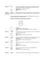
SERVICE 11
LEDOUT
LED Display output; This service routine displays the pattern of LED segments according
to the binary value of the E register to the LED digit specified by the D register. The digits are number 0-5 starting from the first
digit on the right.
If a bit is 1 in any of the 8 bits in the E register it will cause the corresponding segment to shine. Below are
the segments labeled with their corresponding bit numbers.
SEGMENTS LABELED WITH THEIR CORRESPONDING BIT NUMBERS
4
╔═════╗
1║
2 ║5
╠═════╣
0║
║6
╚═════╝
7
INPUT
OUTPUT
SERVICE 12
LEDHEX
INPUT
OUTPUT
SERVICE 13
LEDDEC
INPUT
OUTPUT
SERVICE 14
DELAY
* 3
REGISTER C: 11
REGISTER E: Pattern of segments to display.
REGISTER D: 0 selects the digit farthest right and 5 selects the one farthest left.
NONE
LED Hexadecimal output; This service routine displays the number in the DE register pair
in hex, in the four displays on the left.
REGISTER C: 12
REGISTER PAIR DE: 16 bit number to be displayed in HEX.
NONE
LED Decimal output; This service displays a number in the DE register pair in decimal, in
the four displays on the left. The maximum decimal value displayed is 9999.
REGISTER C: 13
REGISTER PAIR DE: number to be displayed in Decimal.
NONE
OUTPUT
Delay according to the value of the HL register pair. The larger the value, the longer the
Delay.
REGISTER C: 14
REGISTER PAIR HL: Amount of delay.
NONE
SERVICE 15
PTBIN
INPUT
OUTPUT
Return the complement of input port B. This is similar to the DIPSWIN service.
REGISTER C: 15
REGISTER L: Complement of data input to port B
SERVICE 16
KEYSTAT
Return the status of the keypad in the HL register pair. If a key has been pressed H will
INPUT
be 1 and L will contain the value of the key, otherwise HL will be 0. Keys "0-F" return 000F hex respectively and the "Step", "Func.", "Dec.", and "Enter" keys return 14-17 hex
respectively.
REGISTER C:16
REGISTER PAIR HL: Keypad status
INPUT
OUTPUT
SERVICE 17
DIGOUT
Show the hex digit in E on the display in D. The value for E must be less than 10 hex.
The value in D should be a number from 0 to 5, with 0 denoting the rightmost display and
5 the leftmost.
REGISTER C:17
REGISTER E: Hex digit to show
REGISTER D: Display to put digit
NONE
INPUT
OUTPUT
SERVICE 18
RANGE
WRSCL
Write 8 bytes of memory, starting from the address in DE, to the optional real time clock.
The clock provides timekeeping information in BCD including hundredths of seconds,
seconds, minutes, hours, day, date, month and year information. The date at the end of
the month is automatically adjusted for months with less than 31 days, including
correction for leap years. The real time clock operates in either 24-hour or 12-hour
format with an AM/PM indicator. The data pointed to by DE will be stored in the real time
clock as follows:
BIT 7
BIT 0
0.1 SEC
DE
0.01 SEC
00-99
DE + 1
0
10 SEC
SECONDS
00-59
DE + 2
0
10 MIN
MINUTES
00-59
HOURS
01-12
HOURS
00-23
1
DAY
01-07
10 DAY
DATE
01-31
MONTH
01-12
YEAR
00-99
(AM/PM mode)
1
0
AM/PM 10 HR
DE + 3
(24 hour mode)
0
0
DE + 4
0
0
DE + 5
0
0
DE + 6
0
0
DE + 7
10 HOUR
STOP
0
10 YEAR
10MTH
If bit 7 of address DE + 3 is 0 the clock will be in 24 hour mode after WRSCLK is
executed. If it is 1 then AM/PM mode is selected and bit 5 of address DE + 3 will select
AM or PM (PM is selected if bit 5 is 1). When changing from AM/PM mode to 24 hour
mode and vice-versa you must change the hours to match the selected mode. Once the
hours are correct, the real time clock will maintain the correct hour for the selected mode.
If bit 5 of address DE + 4 is set to 1 and WRSCL is executed, the real time clock will be
stopped. The clock may be restarted by resetting the bit to 0 and executing WRSCL.
INPUT
OUTPUT
SERVICE 19
RDSCL
INPUT
OUTPUT
REGISTER C: 18
REGISTER PAIR DE: Address of the first of 8 bytes to be written to the real time clock.
NONE
Read 8 bytes of data from the optional real time clock and store them in the 8
consecutive bytes starting at the address in the DE register pair. The 8 bytes are
formatted the same as the data passed to WRSCL.
REGISTER C: 19
REGISTER PAIR DE: Starting address to store the 8 bytes read from the real time clock.
NONE
Below is an example of using an EMOS service to display the character '0' to the display screen:
ASSEMBLY LANGUAGE
;OUTPUT THE CHARACTER 0 TO THE DISPLAY SCREEN
ORG
8F01H
START:
MVI
C,3
; CONOUT SERVICE ROUTINE
MVI
E,30H
; MOVE ASCII VALUE FOR 0 TO E
CALL
1000H
; CALL EMOS FOR CONOUT SERVICE
RST
7
; RETURN TO MONITOR SYSTEM
END
MACHINE LANGUAGE
ADDRESS
8F01
8F02
8F03
8F04
8F05
8F06
8F07
8F08
DATA
0E
03
1E
30
CD
00
10
FF
COMMENT
; MVI C,3
; MVI E,30H
; CALL 1000H
; RST 7
USING INTERRUPTS
EMOS utilizes both the RST 5.5 and RST 6.5 hardware interrupts so these should not be used except by experienced
programmers. The RST 7.5 interrupt (Highest Priority), however, is available to the user. Since EMOS occupies the lower
32K of memory where the interrupt vectors reside, a vector is provided in RAM at address FFE9. If a RST 7.5 interrupt takes
place and the interrupt is enabled, the Monitor will place the contents of address FFE9 in the Program Counter. Care should be
exercised when using interrupts as not to tamper with interrupts other than the RST 7.5. When utilizing interrupts, the Trace
feature of the Monitor System may not function correctly. When using interrupts it is recommended to run your program at full
speed for predictable results.
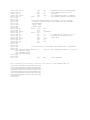
Below is an example program which uses the RST 7.5 interrupt. The program loads the vector at FFE9 with the address of the
program's interrupt service routine (ISR) and the 8155 timer is set up to provide a 20hz square wave. The program then enables
the RST 7.5 and 5.5 interrupts an enters an infinite loop which repeatedly reads a memory address and outputs the data to the
digital output LEDs. Each time an interrupt occurs, this memory value will be incremented. The RST 5.5 interrupt was enabled,
so the program could be stopped by pressing a key at the terminal. If the program is stopped this way, the interrupts are
disabled and the program must be started from the beginning before it will work properly again.
vec7hlf
leds
timerlo
timerhi
timer
cmdreg
loop:
ticsub:
cntout
equ
FFE9h
equ
11h
; 8155 timer ports
equ
14h
equ
15h
; vector for 7.5 interrupt
; discrete LED port
equ
10h
; command register
org
di
lxi
shld
mvi
out
mvi
; output mode
0ff01h
out
mvi
out
mvi
sim
ei
timerhi
a,0cdh
cmdreg
a,11010b
h,ticsub
vec7hlf
a,0
timerlo
a,7ch
; low byte of timer
; hi byte and mode of
; disable interrupts
; hl = address of ISR
; Store in vector
; lo 8 bits of counter=0
; set 8155 square wave
; with timer at 20hz
;
;
;
;
enable the timer
a 0 bit enables the interrupt
enable 7.5 and 5.5
enable interrupts
; this is the main loop that will be interrupted
; by the ISR
lda
cntout
;counter to output to LEDs
out
leds
; display value of A register
jmp
loop
; jump to loop
; This ISR increments CNTOUT
push
psw
lda
cntout
inr
a
sta
cntout
pop
psw
ei
ret
ds
end
1
;
;
;
;
;
;
;
save A and flags
get counter value
increment it
save it back
restore A and Flags
Re-enable interrupts
continue from point of interruption
; reserve 1 byte for the counter
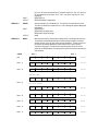
Below are the actual hex codes of the program.
ADDRESS
FF01
FF02
FF03
FF04
FF05
FF06
FF07
FF08
FF09
FF0A
FF0B
FF0C
FF0D
FF0E
FF0F
FF10
FF11
FF12
FF13
FF14
FF15
FF16
FF17
FF18
FF19
FF1A
FF1B
FF1C
FF1D
FF1E
FF1F
FF20
FF21
FF22
FF23
FF24
FF25
FF26
FF27
FF28
FF29
FF2A
FF2B
DATA
F3
21
20
FF
22
E9
FF
3E
00
D3
14
3E
7C
D3
15
3E
CD
D3
10
3E
0B
30
FB
3A
2B
FF
D3
11
C3
18
FF
F5
3A
2B
FF
3C
32
2B
FF
F1
FB
C9
00
INSTRUCTION
DI
LXI
H,FF20
SHLD
FFE9
MVI
A,0
OUT
14
MVI
A,7C
OUT
15
MVI
A,CD
OUT
10
MVI
A,0A
SIM
EI
LDA
FF2B
OUT
11
JMP
FF18
PUSH
LDA
PSW
FF2B
INR
STA
A
FF2B
POP
PSW
EI
RET
(The counter value)
TERMINATING PROGRAMS
Each user program should end with the RST 7 ( FFH ) software interrupt instruction. This instruction allows the
Monitor to regain control of the CPU. The Monitor uses the RST 7 instruction also to implement a breakpoint when using the Go
command. If additional breakpoints are required, RST 7 instructions can be hand inserted at the appropriate spots in the user's
program. It is the user's responsibility to remove the hand inserted breakpoints when they are no longer needed.
USE OF RAMDISKS
The PRIMER can be purchased with an optional RAMDISK. The RAMDISK provides 32k of non-volatile battery
backed RAM. Power to the PRIMER can be shut off without losing programs that have been stored on RAMDISK. RAMDISKS
can even be removed from the PRIMER (when the power to the PRIMER is off) and inserted into another PRIMER, much like a
floppy disk.
There are two memory slots on the PRIMER trainer. The first contains an EPROM which holds the EMOS and the
second contains a 32K x 8 RAM which is used as standard user memory. The EMOS has partitioned 20k of this RAM to be used
for RAMDISK. An optional real time clock (which also provides battery backup of a 32k RAM) may also be inserted in this slot.
The EMOS provides a standard method of access to RAMDISKs through the "B" (Bring Block) and "W" (Write Block)
commands. The "B" command loads data from the RAMDISK into user memory and the "W" command copies a section of user
memory to the RAMDISK. These commands allow the user to read and write programs or data to the RAMDISKs for storage.
To write memory to RAMDISK the user selects the "W" command from the menu. The monitor then prompts the user for the
source address. This address is usually the starting address of the program/data (normally at 8F01H). It is extremely important
when saving programs to RAMDISK that the user remembers this starting address in order to retrieve the program to correct
location. If programs are retrieved to the wrong memory address the program may not execute properly due to incorrect jump
addresses etc. Therefore EMAC suggests using the address 8F01H as the starting address for all programs.
After specifying the source address the user must then specify the starting block number. The RAMDISK is divided
into sections called blocks. Each block is 256 bytes in length, so there are 75 blocks in the 19k reserved for the RAMDISK. It is
also important to remember the starting block number so that programs/data may be retrieved later. EMAC suggests, in the
case of more than one user, that each user be given his own set of consecutive blocks for program storage.
After entering the starting block number the EMOS asks for the number of blocks. The user calculates how many
blocks of storage are required to save his program and enters this value.
Once a program is saved using the "W" command it can be retrieved at any time and as many times as necessary
using the "B" command. When using the "B" command the user is prompted for the destination address. This address should
be the same as the source address used when saving, usually 8F01H (see above). After the user specifies the destination
address, EMOS requests the starting block number. Once again, this is the same starting block number used when saving.
After entering the starting block number, the user enters the number of blocks which is usually the same number used when
saving. Retrieving a program is basically accomplished in the same manner as saving a program.
You can still use the RAMDISK commands even if the RAM in slot two is not battery backed. You can save and
retrieve data but when you turn off the power the data in the RAM is lost.
Warning: A program gone astray could possibly wipe out information stored on the RAMDISK. If you have access to a terminal
emulation program, using the "Hex Download" command would be a safer alternative for program storage.
HARDWARE REFERENCE
HARDWARE RESET
The PRIMER board can be reset through the reset button provided on the board. There is a reset output pin on the
expansion connector which allows the resetting of the PRIMER to reset any devices that may be connected to the expansion
connector.
SERIAL COMMUNICATION PORT
The PRIMER uses an RS232 standard serial communication port. The port interfaces to a PC or terminal through a
DB-9 shell connector (communication cables are available as an accessory from EMAC).
The serial communication rate (or baud rate) must be set to the rate used by the terminal or PC. Placement of jumper
JP1 can set the baud rate from 300 baud up to 19,200 baud. EMOS services are available which access the 8251 serial
communication port.
DIP SWITCH
The dip switch has 8 switches which may be used for applications such as selection of program options. The dip
switch is connected to the system data bus and is accessed through I/O, address 012H. See Appendix C "Assembly Language
Drivers" for information on accessing the dip switch. EMOS services are available which access the dip switch.
DIGITAL OUTPUTS
The PRIMER has 8 outputs and each output can be independently programmed to an ON (+5v or binary 1) or OFF (0v
or binary 0) state. The outputs are connected directly to the digital output LEDs and an LED can be turned on by the output of a
binary 0, and turned off by the output of a binary 1. The outputs are also connected to the digital I/O connector CN3.
The output is driven by the 8155 I/O I.C. which, in the standard configuration, uses PORT A (11H) as the output port,
PORT B (12H) as the input port and PORT C (13H) as an analog output port.
NOTE:
The standard configuration of the 8155 which is set up by EMOS should not be changed. Also, since PORT A outputs
have limited drive capabilities, buffering should be considered if these outputs are to be used by external devices.
DIGITAL INPUTS
The PRIMER allows 8 inputs through 8155 port B. These inputs are connected directly to the 8 station dip switch. The
inputs are also connected to digital I/O connector CN3, so if the dip switches are all turned off, you may connect external TTL
level input devices through this connector.
D/A
An analog output voltage in the range of approximately 0 to +5v can be output from the PRIMER. This digital to analog
converter is implemented through an R-2R ladder which is connected to bits 0-5 of output PORT C. The output from the R-2R
ladder is available on pin 19 of the Analog I/O connector CN3. EMOS provides a service which uses this D/A converter.
A/D
The PRIMER provides an analog input (Analog I/O Connector CN3 pin 20) which can convert a voltage in the range of
0 to +5 volts to a 6 bit value. This conversion is done by an EMOS service using the D/A convertor and a comparator. The
service starts by outputting 0 volts from the D/A convertor and then increasing the output voltage until the comparator senses
that the output voltage exceeds the input voltage. When the input voltage has been exceeded, the last number that was output
to the D/A convertor is the digital representation of the analog input voltage. The driver that performs this conversion is in
Appendix C "Assembly Language Divers", and the schematic of the circuitry for D/A and A/D is in the Self Instruction Manual on
schematic page 6.
NOTE:
Since the service that performs the A/D conversion uses the D/A convertor, the D/A convertor cannot be used at the
same time an analog signal is being converted to digital.
TIMER/COUNTER
The PRIMER comes equipped with a 14 bit timer/event counter. This timer/counter is resident in the 8155 I/O I.C. By
loading a user programmable termination count, time intervals from 3.25 microseconds to 53.3 milliseconds can be achieved.
When the termination count is reached, a RST 7.5 interrupt can then be issued to the CPU. If interrupts are not desirable the
timer can be read directly or the interrupt line can be polled. The timer can also be set up to reload itself or to stop counting upon
reaching the termination count. In either case, an interrupt can be issued.
NOTE: See the section on interrupts under software reference.
The timer/counter is a 14 bit down counter that counts the 'timer input' pulses and provides a pulse or square wave to
the 8085 RST 7.5 interrupt when the terminal pulse is reached. The user can reprogram the length of the count before the
termination pulse is reached if so desired. The user can also determine the timer interval by programming the counter register
from values 2H to 3FFFH. The timer/counter has four operating modes which are:
Mode 0 No operation mode (NOP) does not affect the timer.
Mode 1 Stop mode stops the timer/counter if it is running otherwise NOP.
Mode 2 Stops the timer if running immediately after the terminal count has been reached otherwise NOP.
Mode 3 The start mode loads the output mode and count length and starts the timer/counter immediately if timer is not running,
otherwise it waits for the terminal count then starts the timer/counter.
The timer/counter has four output modes which are as follows:
Mode 0 Outputs a low during the second half of the count, which is equivalent to a single square wave.
Mode 1 Outputs a continuous square wave when the terminal count is reached.
Mode 2 Outputs a single pulse when the terminal count is reached.
Mode 3 Outputs a single pulse and reloads automatically.
The timer/counter operating modes are programmed through the 8155 control register (I/O address 10H). The lower 8 bits of the
count length is written to I/O address 14H. The upper 6 bits of the count length along with the 2 bit output mode is written to I/O
address 15H.
The timer/counter can be used as an external program interval timer. If you wish to perform a software operation at a
specific time interval, then the timer/counter can be programmed to that interval. Upon the resulting timer interrupt your program
can execute the desired software (refer to Appendix C "Assembly Language Drivers" for timer/counter set-up.)
The timer/counter is also used to drive the PRIMER's speaker. Different frequencies can be output from the speaker
using the PITCH EMOS service (see EMOS SERVICES).
ADDITIONAL DETAILS ON THE 8155 TIMER/COUNTER MAY BE OBTAINED FROM INTEL CORPORATION'S
LITERATURE DEPARTMENT.
EXPANSION CONNECTOR
The PRIMER has a 40 pin expansion connector (CN1) on board which provides additional expansion capabilities.
Primarily, this port gives access to the Data and Low Address Busses and Control Lines. See Appendix A "EXPANSION
CONNECTOR CN1" drawing for a detailed description.
NOTE:
EMAC HAS MODULAR EXPANSION BOARDS AVAILABLE FOR THIS CONNECTOR.
OPTIONAL ON BOARD HARDWARE FEATURES
REAL TIME CLOCK CALENDAR:
The PRIMER can be equipped with a real time clock/calendar (RTC). The RTC contains a lithium energy cell which
maintains clock information and RAM memory data. The clock keeps time in hundredths of seconds, seconds, minutes, hours,
day of week, date of month, month and year. The month and year determine the number of days in each month. If you have the
real time clock option refer to the specification sheet included in your RTC Supplement for technical and programming
specifications. This option can be installed at any time by the user or at the factory before shipping.
32K x 8 NON-VOLATILE RAM (RAMDISK):
EMAC has an 32K RAMDISK available for source code or data storage. The RAMDISK has a built-in lithium energy
cell which maintains data in RAM memory. The RAMDISK resides in the memory socket (U1). Source code or data can be
written into and stored for later use in the RAMDISK. The RAMDISK may be removed from the PRIMER and replaced at a later
time without loss of memory which allows the RAMDISKS(s) to be removed/inserted much like floppy disks.
OTHER OPTIONS FOR THE PRIMER
EPROM PROGRAMMER BOARD:
A simple solution to making permanent EPROM resident programs.
PROGRAMMABLE 32 LINE PARALLEL BOARD:
An alternative to the E-PAC EXPANSION Board when 32 lines of I/O are sufficient.
SUPPORT SOFTWARE:
When your PRIMER needs to communicate with PCs.
APPENDIX A
JUMPER DESCRIPTIONS
JUMPER
JP1
DESCRIPTION
This allows the selection of one of the following baud rates: 300, 600, 1200, 4800, 9600 and 19,200.
OJ1
This is used to select the sources for the 8085's RST 5.5 and RST 6.5 interrupt inputs. The RST 5.5 interrupt
pin is connected to the 8279 interrupt request line when there is a connector between pins 4 and 5, or, if a
connector is between pins 3 and 4, it is connected to the 8251 receiver ready line. The RST 6.5 interrupt pin
is connected to the 8251 receiver ready line when there is a connector between pins 2 and 3. Putting a
connector between pins 1 and 2 connects RST 6.5 to +5v. This jumper can also be used to connect RST 5.5
and RST 6.5 to external interrupt sources. Pin 2 of the jumper is connected to RST 6.5 and pin 4 is
connected to RST 5.5.
0J2
This jumper selects the EPROM size. Position 'A' allows an 8 or 16K EPROM to be placed in slot 0 and
position 'B' allows a 32K EPROM to be placed in the slot.
0J3
This selects one of the two memory maps which are as follows:
POSITION 'A' MEMORY MAP
SLOT 0
0000 TO 3FFF
SLOT 1
4000 TO BFFF
8155 RAM
C000 TO FFFF (only 256 bytes available)
POSITION 'B' MEMORY MAP
SLOT 0
0000 TO 7FFF
SLOT 1
8000 TO FFFF
8155 RAM
(not accessible)
APPENDIX B
I/O AND MEMORY ADDRESS DESCRIPTIONS
REFERENCE
I/O ADDRESS
DESCRIPTION
8251 DATA REGISTER
80 H
DATA INPUT/OUTPUT
8251 CONTROL REGISTER
81 H
CONFIGURATION
8155 CONTROL REGISTER
10 H
CONFIGURATION
PORT A
11 H
OUTPUT PORT
PORT B
12 H
INPUT PORT
PORT C
13 H
ANALOG OUTPUT PORT
TIMER LOW
14 H
LOW ORDER TIMING BYTE
TIMER HIGH
15 H
HIGH ORDER TIMING BYTE & CONTROL
EXPANSION I/O
C0 - FF H
EXPANSION CONNECTOR
------------------------------------------------------------------------------------
MEMORY
ADDRESS
DESCRIPTION
For OJ3 position A
0000 H
-
3FFF H
EPROM SLOT
4000 H
-
BFFF H
32K RAM SLOT
C000 H
-
FFFF H
256 BYTES IN 8155 (with multiple addresses)
0000 H
-
8000 H
EPROM SLOT
8000 H
-
FFFF H
32K RAM SLOT
For OJ3 position B
APPENDIX C
ASSEMBLY LANGUAGE DRIVERS
;
PRIMER SOURCE DRIVERS
INIT
MVI
OUT
RET
PTAOUT
CMA
OUT
RET
A,0DH
10H
;
;
INITIALIZE THE ( 8155 ) PORTS
PORT A OUTPUT, PORT B INPUT, PORT C OUTPUT
11H
;
;
CONTENTS OF ACCUMULATOR IS WRITTEN TO
OUTPUT PORT A
RETURNS CONTENTS OF OUTPUT PORT A IN
ACCUMULATOR (AFTER COMPLEMENTING)
PTAIN
IN
CMA
RET
11H
;
;
PTBIN
IN
CMA
RET
12H
; RETURNS CONTENTS OF INPUT PORT B (DIPSWITCH)
; IN ACCUMULATOR (AFTER COMPLEMENTING)
DPSWIN
IN
CMA
RET
012H
; RETURNS DIP SWITCH SETTING IN ACCUMULATOR
; **********************************************************************
;
ACCEPTS TIMER MODE AND COUNT LENGTH IN H,L REGISTER PAIR
;
ACCEPTS TIMER COMMAND IN BIT POSITION 0 AND 1 OF ACCUMULATOR
;
REFER TO INTEL MICROSYSTEM COMPONENTS HANDBOOK VOL. II FOR
;
ADDITIONAL INFORMATION ON ( 8155 ) IC.
TIMER
TIM1
PUSH
MOV
MOV
OUT
MOV
OUT
XRA
ORA
JZ
ANI
RRC
RRC
ORI
OUT
POP
RET
B
B,A
A,L
14H
A,H
15H
A
B
TIM1
03H
; OUTPUT TIMER LOW BYTE
; OUTPUT TIMER MODE AND HIGH BYTE
; NO OPERATION
; MOVE BITS 0 AND 1 TO BIT POSITIONS 6 AND 7
0DH
10H
B
; OUTPUT TIMER COMMAND
;
; Speaker controller. If SOD is on, speaker is on and vice versa
buzzon:
mvi
b,0c0h
; this turns on SOD pin
jmp
sod
buzzoff:
mvi
b,40h
; this turns off SOD pin
sod:
rim
ani
ora
sim
ret
1fh
b
; Send the frequency in HL to 8155.
sdiv:
mov
a,l
out
14h
mov
a,h
mvi
a,3fh
ana
h
ori
40h
out
15h
mvi
a,0cdh
out
10h
ret
; B E E P :
beep:
dlay:
HL is limited to <=3fffh
; timer frequency low byte
; timer frequency mode and hi byte
; output timer command
This beeps the speaker.
push
h
lxi
h,0200h
call
sdiv
; set the frequency
call
buzzon
lxi
h,03000h
call
dlay
call
buzzoff
pop
h
ret
dcx
mov
ora
jnz
ret
h
a,h
l
dlay
; **********************************************************************
; COM1 8251 UART DRIVER ROUTINES
; INITIALIZE THE 8251 TO 8 DATA BITS, NO PARITY
SERDTA
SERCOM
EQU
EQU
80H
81H
COMINIT
MVI
OUT
MVI
OUT
RET
A,0CEH
SERCOM
A,27H
SERCOM
; INPUT A CHARACTER INTO THE ACCUMULATOR FROM THE 8251
COMIN
IN
ANI
JZ
IN
RET
SERCOM
02
COMIN
SERDTA
;
WAIT FOR CHARACTER TO BE SENT
; OUTPUT A CHARACTER IN THE ACCUMULATOR
COMOUT
COMOUT0
MOV
IN
ANI
JZ
MOV
OUT
RET
L,A
SERCOM
01
COMOUT0
A,L
SERDTA
;
WAIT FOR TRANSMITTER CLEAR
;****************************************************************************
; DACOUT: This converts the 6 bit value in A to a proportional voltage on
; pin 19 of Analog I/O connector CN3.
dacout:
ani
00111111b
; mask off extra bits
out
13h
; port C
ret
;***********************************************************************
; ADCIN converts a voltage on pin 20 of digital I/O connector CN3 to a 6 bit
; number in L. The PRIMER has a comparator which compares the analog input
; voltage to the analog output voltage. When the output voltage exceeds
; the input voltage the comparator will cause the SID input line to go high.
; This program outputs the value of the L register to port C which generates a
; output voltage proportional to the value of L. The value of L is
; incremented and output to port C until the SID input line goes high. When
; SID goes high, L is the digital representation of the input voltage.
ADCIN:
push
psw
Mvi
l,-1
; l starts at the lowest voltage -1
adcin1:
inr
l
mov
a,l
out
13h
; send a voltage out of the R-2R
ladder
rim
; has it exceeded the input voltage?
ora
a
; SID will be high if so.
Jm
adcin2
; if A is negative, exit
Mov
a,l
Cpi
63
Jc
adcin1
; if l<63 increment and output the
next voltage
adcin2:
xra
a
out
13h
; set d/a to 0 volts
pop
psw
ret
;****************************************************************************
; Initialize the 8279 keypad and display controller
in8279:
mvi
a,0
; select eight 8 bit character display, with
out
41h
; encoded scan keyboard - 2 key lockout
mvi
a,3fh
; program clock for input freq. Divided by 31 decimal
out
41h
mvi
a,0c1h
; clear display RAM
out
41h
lxi
h,0ffffh
call
dlay
; delay for a moment while clearing RAM
mvi
a,80h
; select display 0
out
41h
ret
;****************************************************************************
; RDKEY Waits until key buffer is not empty. When not empty, it will get
; the keypad value and return it in A
; keys 0-f will return 00-0fh
; 10h-13h are not used
; step,func,dec,ent/inc = 14h-17h respectively
rdkey:
rdkey1:
push
push
push
in
ani
jz
mvi
out
in
b
d
h
41h
07h
rdkey1
a,40h
41h
40h
ani
mov
ani
rrc
mov
mov
ani
add
pop
pop
pop
ret
3fh
b,a
00111000b
c,a
a,b
00000111b
c
h
d
b
; see if key buffer is > 0
; loop until key pressed
; clear interrupt
; get the scanned key.
; bit pattern is CNTRL,SHFT,3 bits SCAN,3 bits RETURN
;
;
;
;
;
;
;
;
bit 7 not used
preserve A
masking off all but scan and..
dividing by 2 makes scan=scan*4
c=scan*4
A=original scanned key
mask all but the value for RETURN
add to scan*4
; This outputs the digit in A (0-f) to the display number in B (80-85 hex)
; Displays are numbered 85-80 from left to right
; only hl is preserved
digout:
dmap:
push
lxi
add
mov
mvi
adc
mov
mov
out
mov
out
pop
ret
h
h,dmap
l
l,a
a,0
h
h,a
a,b
41h
a,m
40h
h
db
db
0f3h,60h,0b5h,0f4h,66h,0d6h,0d7h,70h,0f7h ; zero thru
0f6h,77h,0c7h,93h,0e5h,97h,17h
; F
; point to bit map table
; add A to HL
;
;
;
;
;
hl=hl+a
b= 80h-85h
select display
get bit map from (hl)
output bit pattern to the display
APPENDIX D
COMMUNICATION USING ECOM
ECOM is a powerful communication software package that is ideally suited for use with the PRIMER trainer, and with
other EMAC systems. ECOM runs on IBM PCs, and compatibles, using COM ports 1-2 at baud rates of up to 19,200 baud.
ECOM also allows for menu options; like file/printer logging, and fully automated file transfers.
STARTING ECOM
If you have the ECOM disk, you can run the program by placing the disk into a 5.25 inch drive and typing ECOM at the
DOS prompt. A message will appear on the screen describing which trainer system your ECOM is for use with, (in this case,
EMOS). Press the space bar to clear this message and start ECOM.
The main screen of ECOM is an ADM-3A terminal emulation screen with a top menu bar. This main screen is what
you use to communicate with the trainer. Most of what you type is sent directly to the trainer and echoed back onto this screen.
Conversely, the trainer will send messages, such as a command menu or memory dump. This information will also be displayed
on the main screen.
The top menu bar describes functions and pop up windows that are used for things like file transfer, and systems
setup. To use these functions, press the <ALT> key plus the highlighted letter of the function you wish to use. (For monochrome
monitors: Type the <ALT> key plus the capital letter, of a function you wish to use.) In addition, the menu bar lists the current
serial port settings, (baud, parity, etc), and logging status, (FILE, PRN, or none).
SETTING UP ECOM FOR USE WITH THE PRIMER
Once in the main screen, press the <ENTER> key. ECOM should display the EMOS prompt, "-". If this prompt does
appear, you are ready to issue commands through ECOM to your trainer. For example typing a "?" at your keyboard should
result in a command menu list.
If you press the enter key and ECOM does not display a prompt, follow the these steps. First, make sure that your
trainer is set up and operating correctly. For details on this refer to the section of this manual "Getting Started". Once your are
sure the trainer is operating properly, and communications still does not occur, enter the setup menu listed in the top menu bar.
This is done by pressing the <ALT> and "S" keys together.
THE SETUP MENU
The Setup menu is a pull down window that lists seven fields. They are as follows:
Baud
Parity
Length
Stop bit
Comm Port
Protocol
Write
The first six fields are for changing the serial port parameters of your computer to match the settings of your trainer. To
move between these fields, press the UP and DOWN keys on the numeric keypad of your keyboard. (Make sure <Num Lock> is
off.) This will move the highlighted bar over the field you wish to select. To select that field, press the <ENTER> key. To exit the
menu, press the <ESC> key.
When starting your trainer, the first field to be concerned with is the Comm Port field. You will want to change this
field to match the serial port on which the trainer is connected. Move the highlighted bar over the Comm Port field and press
<ENTER>. A sub menu will appear to the right of the first seven fields. This sub menu will allow you to change the current serial
port setting. Use the UP and DOWN keys on your numeric keypad to move between the options, and press <ENTER> to make
a selection.
In addition to your serial port setting, you may also need to change the communications settings. For a typical trainer,
these settings are (9600) baud, (N)o parity, (8) bits, and (1) stop bit. Check your trainer to be sure. To change a
communications setting, such as baud rate, do the same as before. Move the highlighted bar in the setup menu over Baud, and
press <ENTER>. Make a selection in the sub menu, and leave the setup menu by pressing <ESC>.
The top menu bar will display the new port and communications settings. Should you wish to save these settings,
move to the field named Write in the setup menu, and press <ENTER>. ECOM will save the changes in the directory ECOM is
running from. This file will have the extension *.cfg. After this, every time you run ECOM, it will default to the new changes.
FILE TRANSFER FOR EMOS
ECOM for EMOS uploads and dowloads Intel Hex files. Intel Hex files are a standard type of ASCII file produced by
8085 assemblers and some compilers and excepted by EPROM programmers and other hardware devices. If the user
assembles a program, the resulting Intel Hex file can be uploaded, saving the user from entering in the prgram by hand.
Programs that were entered in by hand can be saved to a disk file on the PC by downloading the program to the specified file.
When the program is needed the user can upload the file to the trainer and run it.
ECOM allows for automated file transfers to and from your trainer. To transfer a file, press the <ALT> and "F" keys
together to bring down the file transfer menu. This menu has two options:
Upload to EMAC board
Download from EMAC board
The first option will allow you to send Intel hex files to your trainer, and the second will allow you to receive Intel hex
files from your trainer.
To upload a file to your trainer, enter into the File I/O menu by pressing the <ALT> and "F" keys on your keyboard.
Move the highlighted bar over the Upload to EMAC board field, (it should be highlighted by default), using the UP and DOWN
keys on the numeric keypad of your keyboard. Press <ENTER> and a sub menu will appear which has two fields that look like
this:
Enter PC filename: [drv]:\[pth]\fn.ext
Enter Starting Address: 8F01h
The first field in the sub menu is a prompt for the filename to upload. This filename is the source of the transfer, and
will originate from the PC. Type the name of the file and press <ENTER>. The second field in the sub menu is a prompt for the
destination address on the trainer which defaults to 8F01h. Type the destination address and press <ENTER>. Once you are
done entering the file transfer information, you will be prompted to begin the file transfer. Press the space bar to toggle between
Y or N. Press <ENTER> to select a choice. If you choose Y, the file will be transferred to your trainer. At the end of a
successful transfer, a "FILE TRANSFER COMPLETED" will flash in the main file transfer menu. If the file transfer is interrupted,
an abort message will flash. This is caused by a bad checksum, or a user break (the <ESC> key was pressed twice).
A file download is done by entering the File I/O menu, (<ALT> and "F"), and selecting the Download from EMAC
board field. In this case, the sub menu will appear as follows:
Enter PC filename: [drv]:\[pth]\fn.ext
Enter starting address: 8F01h
Enter last address: 8F01h
Enter offset address: 0000h
The first field is a prompt for the name of the destination file. This will be a file on your PC. If this file already exists, it
will be overwritten, otherwise, ECOM will create it. Type the filename and press <ENTER>. For the meaning of starting address,
last address and offset address, see the description of the EMOS command "<". ECOM will prompt you to start the file transfer.
Toggle between Y or N with the space bar, and press <ENTER>. If you select Y, the file will be transferred from your trainer. At
the end of a successful file transfer, a "FILE TRANSFER COMPLETED" message will flash on the main file transfer menu. An
abort message will flash if there was a user break or checksum error during the transfer.
LOGGING
ECOM allows for screen logging either to a file, to a printer, or to both. To enter the Logging menu, press <ALT> and
"L" at your keyboard. The following fields will be displayed:
Logging to printer: DISABLED
Logging to file: DISABLED
Filename: [drv]:\[pth]\fn.ext
To move between each field, press the UP and DOWN keys on the numeric keypad of your keyboard. Both the printer
and file logging fields have three options: DISABLED, ENABLED, and SOFTWARE ENABLED. Press the space bar to toggle
between these options. Press <ESC> if you need to leave the logging menu. The current logging status, either PRN, or FILE, or
none, is displayed on the menu bar of the main communications screen.
NOTE:
You must specify a filename in the Filename field if you choose either ENABLED or SOFTWARE
ENABLED for the Logging to file field.
The SOFTWARE ENABLED option allows your trainer to turn on and off printer and file logging through special
extended ASCII characters/codes. These characters/codes are as follows:
Printer ON:
Printer OFF:
File write ON:
File write OFF:
AEH
AFH
F3H
F2H
These codes can be sent from the trainer to ECOM, allowing automated printing and file logging without user
intervention. In addition, the trainer can take advantage of the ADM cursor and screen control codes to format display output.
APPENDIX E
UPLOADING & DOWNLOADING INTEL HEX FILES
This example assumes the user is using an IBM PC or compatible computer with an ECOM disk in the A: drive and has
some familiarity with EMOS.
To start the example, first invoke ECOM by typing A:ECOM. Establish communications and verify that correct
communication has taken place (see COMMUNICATION USING ECOM).
UPLOADING
At this point the user has configured ECOM and is successfully communicating with the trainer. The user is now ready
to upload the example assembled program, TRAINTST.HEX. This ASCII file is included on the ECOM disk and contains all the
op codes and operands necessary to upload and subsequently run this program on the PRIMER. The steps to upload are as
follows:
1. Press <ALT> "F" to select File I/O menu.
2. Select the "Upload to EMAC board" option.
3.
At the sub menu PC filename prompt, type TRAINTST.HEX and press enter. Press enter at the starting address
prompt and the default value will be entered
4.
The top line of the screen will have a message asking if you want to transfer the file. Press enter to start file
transfer.
5.
After the upload is complete, press <ESC> to return to the terminal screen and choose the "D" command to do a
memory dump of 70 bytes at address 8F01. The Dump command displays the contents of memory allowing
verification of the upload. The screen should look similar to:
D
STARTING ADDRESS.. 8F01
8F01
8F11
8F21
8F31
8F41
8F51
8F61
NO. OF BYTES.. 70
0 1 2 3 4 5 6 7 8 9 A B C D
6 1 E 3 1E D CD 0 10 1E A CD 0 10
E 4 11 52 8F CD 0 10 E A CD 0 10 6
3 1E 20 CD 0 10 6 1 E D 16 0 5D CD
CD 43 8F 6 1 E 3 1E D CD 0 10 7D B7
8F FF F5 E5 21 0 80 0 2B 7D B4 C2 48 8F
C9 D A A 20 54 48 45 20 44 49 50 53 57
43 48 20 4E 4F 57 20 52 45 41 44 53 20 D
E F 0123456789ABCDEF
6 1
.
.
1 E
R..
.
0 10
.
].
C2 19 .C.
. }..
E1 F1 ....! . +}..H...
49 54 .
THE DIPSWIT
A A CH NOW READS
-
7. Choose the "G" command at address 8F01 with no breakpoint. NOTE: To prevent the program from terminating, at
least one dip switch should be in the ON position.
The program, once executed, will display a message to the screen and then display to the screen the contents of the
dip switch in HEX. To exit the program, set the dip switch to 0 (all off). To suspend the program press any key. Once
suspended the program can continue to run by choosing the "G" command with no options. For more information on the
EMOSTST program see the EMOSTST.LST listing.
DOWNLOADING
In the next part of the example we will modify the program and store it back to disk as an Intel hex file. The
modification to the program will involve changing the dip switch output from being displayed in HEX to being displayed in
Decimal. This involves changing the service call from 0D (PRINTHEX) to 05 (UPRINT). This change is made at address 8F22.
The steps are as follows:
1.
If TRAINTST is still running, stop execution by setting the dip switch to 0 (all off).
2.
Choose the "E" command to edit at address 8F22.
3.
Change 0D to 05 and press <ENTER>.
4.
Press <ESC> to leave the Edit mode.
5.
Choose the "G" command at address 8F01 with no breakpoint. Remember to leave at least one of the dip
switches in the on position to keep the program from terminating. After that, verify that the program is outputting
the dip switch in decimal and stop execution as in step 1.
6.
Press <ALT> "F" to select File I/O menu.
7.
Select the "Download from EMAC board" option.
8.
At the sub menu PC filename prompt, type TEST.HEX and press enter. Press enter at the starting address
prompt and the default value will be entered.
9.
At the last address prompt, type 8F67, and press enter at the offset address prompt and the default of 0000h will
be used.
10. The top line of the screen will have a message asking if you want to transfer thefile. Press enter to start file
transfer.
11. After the download is complete the message "FILE TRANSFER COMPLETE" will be flashing. Press <ESC> to
return to the terminal screen.
The file TEST.HEX is now on residing on floppy in the A: drive. At any time this file can be uploaded to the trainer and
executed following the procedures that were used to load TRAINTST.HEX.
APPENDIX F
TRAINTST.LST LISTING
000001
000002
000003
000004
000005
000006
000007
000008
000009
000010
000011
000012
000013
000014
000015
000016
000017
000018
000019
000020
000021
000022
000023
000024
000025
000026
000027
000028
000029
000030
000031
000032
000033
000034
000035
000036
000037
000038
000039
000040
000041
000042
000043
000044
000045
000046
000047
000048
000049
000050
000051
000052
000053
000054
000055
000056
000057
000058
000059
000060
000061
000062
000063
000064
000065
8F01
8000
1000
000A
0004
000D
0003
=
=
=
=
=
=
=
000D =
000A =
0020 =
8F01
8F01
8F03
8F05
8F07
8F0A
8F0C
8F0F
8F11
8F13
8F16
8F19
8F1B
8F1E
8F20
8F22
8F24
8F27
8F29
8F2B
8F2D
8F2E
8F31
8F34
8F36
8F38
0601
0E03
1E0D
CD0010
1E0A
CD0010
0601
0E04
11528F
CD0010
0E0A
CD0010
0601
0E03
1E20
CD0010
0601
0E0D
1600
5D
CD0010
CD438F
0601
0E03
1E0D
; THIS PROGRAM DEMONSTRATES SOME OF THE CONCEPTS OF ASSEMBLEY
; LANGUAGE USING SERVICE CALLS ON THE TRAINER.
; THIS PROGRAM CAN BE ASSEMBLED AND THE RESULTING HEX FILE
; UPLOADED (USING ECOM, PROCOMM OR SOME OTHER COMMUNICATIONS PACKAGE)
; TO THE TRAINER OR CAN BE HAND ASSEMBLED AND ENTERED
; BY HAND IF A HOST COMPUTER IS NOT AVAILABLE.
;
; NOTE: IF UPLOADING THE PROGRAM FROM A COMPUTER BE SURE TO SPECIFY
;
THE STARTING ADDRESS AS 8F01H. THE REASON BEING THAT THIS
;
PROGRAM IS NOT WRITTEN TO BE RELOCATABLE ( IT USES ABSOLUTE
;
ADDRESSES ). IF A DIFFERENT STARTING ADDRESS IS DESIRABLE
;
CHANGE THE CONSTANT "STARTADD" TO ORG THE PROGRAM AT A
;
DIFFERENT LOCATION AND REASSEMBLE.
;
;
; CONSTANT DECLARATIONS
;
STARTADD EQU
8F01H
; STARTING ADDRESS FOR PROGRAM
DELAYTIM EQU
8000H
; CONSTANT USED TO DETERMINE THE DELAY
MOS
EQU
1000H
; ADDRESS OF MOS OPERATING SYSTEM
DPSWIN
EQU
0AH
; DIPSWITCH SERVICE NUMBER
PSTRING EQU
04H
; PRINT STRING SERVICE NUMBER
HEXPRINT EQU
0DH
; HEX PRINT SERVICE NUMBER
CONOUT
EQU
03H
; CONSOLE OUTPUT SERVICE NUMBER
;
CR
EQU
0DH
; ASCII CARRAGE RETURN
LF
EQU
0AH
; ASCII LINE FEED
SPACE
EQU
20H
; ASCII SPACE
;
;
; THIS PROGRAM DISPLAYS A GREETING MESSAGE AND THEN WILL
; PROCEED TO DISPLAY THE CONTENTS OF THE DIP SWITCH TO THE
; CONSOLE UNTIL THE DIP SWITCH EQUALS ZERO. AT THIS POINT THE
; PROGRAM WILL RETURN CONTROL TO THE MONITOR.
;
;
ORG
STARTADD ; TELL THE ASSEMBLER WHERE TO START
MAIN:
LOOP:
MVI
MVI
MVI
CALL
MVI
CALL
MVI
MVI
LXI
CALL
MVI
CALL
MVI
MVI
MVI
CALL
MVI
MVI
MVI
MOV
CALL
CALL
MVI
MVI
MVI
B,COMPORT
C,CONOUT
E,CR
MOS
;
E,LF
MOS
;
B,COMPORT
C,PSTRING
D,MESSAGE
MOS
;
C,DPSWIN
MOS
;
B,COMPORT
C,CONOUT
E,SPACE
MOS
;
B,COMPORT
C,HEXPRINT
D,0
E,L
MOS
;
DELAY
;
B,COMPORT
C,CONOUT
E,CR
OUTPUT A CR TO THE CONSOLE
OUTPUT A LF TO THE CONSOLE
OUTPUT THE MESSAGE TO THE CONSOLE
INPUT THE CONTENTS OF THE DIPSWITCH
OUTPUT A SPACE TO THE CONSOLE
OUTPUT THE CONTENTS OF THE DIPSWITCH
DELAY THE NEXT PRINTING
000066
000067
000068
000069
000070
000071
000072
000073
000074
000075
000076
000077
000078
000079
000080
000081
000082
000083
000084
000085
000086
000087
000088
000089
000090
000091
000092
000093
000094
8F3A
8F3D
8F3E
8F3F
8F42
8F43
8F43
8F43
8F43
8F43
8F43
8F43
8F43
8F43
8F44
8F45
8F48
8F49
8F4A
8F4B
8F4C
8F4F
8F50
8F51
8F52
8F52
8F52
8F52
8F52
8F5A
8F62
8F6A
000095 8F72
000096 8F72
000097 8F72
CD0010
7D
B7
C2198F
FF
CALL
MOV
ORA
JNZ
RST
MOS
A,L
A
LOOP
7
;
;
;
;
;
RETURN THE CURSOR TO THE BEGINNING
MOVE DIPSWITCH VALUE TO A REG.
SET FLAGS
IF DIPSWITCH NOT EQUAL 0 CONTINUE
ELSE RETURN CONTROL TO THE MONITOR
STOP:
;
;
; THIS SUBROUTINE PERFORMS A 16 BIT DELAY. THE 16 BIT DELAY
; CONSTANT IS PLACED IN THE H/L REGISTER PAIR. ALL REGISTERS
; ARE PRESERVED.
; INPUT: NONE
; OUTPUT: NONE
;
F5
DELAY:
PUSH
PSW
E5
PUSH
H
210080
LXI
H,DELAYTIM
00
DLOOP:
NOP
2B
DCX
H
; DCX DOES NOT SET FLAGS SO OR H & L
7D
MOV
A,L
; TOGETHER AND IF THE RESULT IS 0
B4
ORA
H
; WE'RE DONE
C2488F
JNZ
DLOOP
E1
POP
H
F1
POP
PSW
C9
RET
;
;
; ASCII MESSAGE TO BE DISPLAYED. DON'T FORGET THE '$' DELIMETER.
;
0D0A0A2054484520 MESSAGE: DB
CR,LF,LF," THE DIPSWITCH NOW READS ",CR,LF,LF,'$'
4449505357495443
48204E4F57205245
414453200D0A0A24
;
;
END
MAIN
; STOP ASSEMBLING
After assembling, the following is similar to the contents of the TRAINTST.HEX file:
:108F010006010E031E0DCD00101E0ACD0010060134
:108F11000E0411528FCD00100E0ACD001006010E65
:108F2100031E20CD001006010E0D16005DCD0010B0
:108F3100CD438F06010E031E0DCD00107DB7C21962
:108F41008FFFF5E5210080002B7DB4C2488FE1F150
:108F5100C90D0A0A205448452044495053574954E1
:108F61004348204E4F57205245414453200D0A0A91
:018F710024DB
:0000000000