1
321-78013A
MAR. 2013
MOC63u
P.24
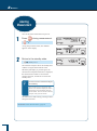
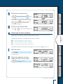
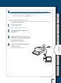
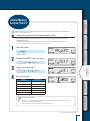
Measuring Moisture Content
Aborting Measurement
After Measurement
Turning Power Off
P.44
P.48
P.49
P.50
P.25
P.32
P.38
P.42
P.85
P.91
P.98
P.102
P.104
P.105
P.106
P.107
P.110
P.113
TROUBLESHOOTING GUIDE
AND OTHER INFORMATION
Troubleshooting Guide
When Required
P.79
MAINTENANCE
Maintenance of
Moisture Analyzer
Replacing Heater
Replacing Fuses
Clearing Measurement
Data from Memory
Initializing Moisture Analyzer
Settings
Inspection
P.78
CONNECTION TO
PERIPHERALS
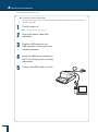
When Connecting MOC63u
to Peripheral Devices
Using Windows
Direct Function
Control Moisture Analyzer
from PC
Printer Output (Option)
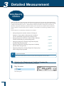
DETAILED
MEASUREMENT
Setting Measuring Conditions P.52
Changing Moisture Analyzer
Settings
P.63
Calibrating Moisture Analyzer P.73
MEASURE
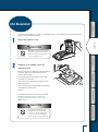
Checking Package Contents
Names and
Functions of Parts
Installation
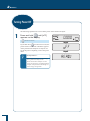
Preparing for Measurement
Menu
BEFORE MEASUREMENT
Moisture Analyzer
Instruction Manual
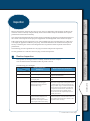
Requests
•
If you lend or transfer this product to others, attach this instruction manual to the product.
•
If you lose or damage this instruction manual, contact your Shimadzu sales representative immediately.
Remarks
•
The information in this instruction manual is subject to change without notice for the purpose of
improvement.
•
All information in this instruction manual has been carefully verified to ensure its accuracy. Any errors
or missing information, should any be found, may not be corrected immediately.
•
Shimadzu Corporation (the Company) owns the copyright to this instruction manual. Neither part nor the
entirety of this document may be transferred or reproduced without the prior written permission of the
Company.
© 2010-2013 Shimadzu Corporation. All rights reserved.
•
Microsoft, Windows, and Excel are the registered trademarks of Microsoft Corporation. All other
company names and product names in this document are the trademarks and registered trademarks of
their respective owners. The symbol that represents the trademark or ® is not used in this document.
•
Company names, organization names, product names, etc. in this document are the trademarks or
registered trademarks of their respective owners.
•
The Company does not guarantee that Windows Direct Function can run normally on all personal
computers. The Company is not responsible for any problems caused by this function.
Introduction
Thank you for choosing the MOC63u, Shimadzu Moisture Analyzer.
Shimadzu Corporation, with more than 90 years experience in manufacturing high
precision balances, is confident in the high quality of the MOC63u moisture analyzer.
The MOC63u provides prompt and accurate measurement of moisture contents. With
the full adoption of UniBloc® cell, which we started to use for electronic balances
in 1989, the MOC63u also features improved reliability. The cross key dedicated to
menu manipulation has improved the operability of the MOC63u, making it easier to
use.
The MOC63u is also equipped with the Windows Direct Function that can transmit
measurement results to a PC without requiring any software to be installed, as well
as other various functions that users can use conveniently according to their aims.
To make full use of the performance and functions of the MOC63u moisture
analyzer, please read this instruction manual carefully, and follow the usage
instructions. Please keep this instruction manual with the product, so that you can
refer to the manual at anytime necessary.
You can download the instruction manual (PDF format) from our web site
(http://www.shimadzu.com/an/balance/index.html).
For information on the following points, please contact your Shimadzu Balance
representative.
•
•
Product warranty
After service
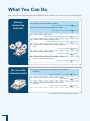
What You Can Do
You can search the usage instructions for information about functions you want to try or learn about by aim.
Various
measuring
methods
n I want to measure moisture content!
Measuring Moisture Content
page 44
n I want to set measuring conditions in detail!
Setting Measuring Conditions page 52
n I want to measure data easily!
Standard Drying Automatic Ending Mode
page 53
n I want to measure data by setting the time!
Standard Drying Timed Ending Mode
page 55
n I want to measure samples that change largely with
heat!
Slow Drying Mode
page 58
n I want to measure liquid samples!
For accurate
measurements
Rapid Drying Mode
page 56
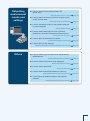
n I want to measure the amount of change in moisture
content at different temperatures!
Stepped Drying Mode
page 60
n I want to measure data accurately with the moisture
analyzer!
Calibrating Moisture Analyzer
page 73
n I want to span calibration of the moisture analyzer!
Span calibration
page 73
n I want to calibrate the temperature of the moisture
analyzer!
Calibrating the Temperature (*1)
page 73
(*1) The temperature calibration kit (option) is required.
Outputting
measurement
results and
settings
n I want to transfer the measured data to PC (Excel, etc.)!
Using Windows Direct Function
page 79
n I want to set the ID for each moisture analyzer unit to
control several units!
Setting the Moisture Analyzer ID
page 72
n I want to set sample codes for the moisture analyzer
to control samples!
Setting Sample Codes
page 67
n I want to set the date and time for the moisture
analyzer to control the measurement date and time!
Setting the Date and Time page 68
n I want to print out measurement results!
Printing Stored Measurement Data
page 93
n I want to print out the settings!
Outputting the Moisture Analyzer Settings from a Printer
Others
page 94
n I want to switch types of values to be referenced for
measurement!
Setting the Measurement Standard
page 63
n I want to restrict menu items to be displayed!
Restricting the Menu Display
page 69
Setting the Password
page 70
n I want to set the password!
n I want to clear measurement data from memory!
Clearing Measurement Data from Memory
page 105
n I want restore the default settings of the moisture
analyzer!
Initializing Moisture Analyzer Settings
page 106
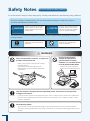
Safety Notes
Be sure to follow the safety guidelines
To use the moisture analyzer safely and properly, carefully read and observe the following safety guidelines.
The levels of danger and damage that will arise if the moisture analyzer is used incorrectly are
classified and indicated as shown below.
! Warning
Indicates a potentially hazardous
situation which, if not avoided,
could result in serious injury or
possibly death.
! Caution
Indicates a potentially hazardous
situation which, if not avoided,
may result in minor to moderate
injury or equipment damage.
Precautions are classified and explained by using one of the symbols below, depending on the nature
of the precaution.
Indicates an action that must be
performed.
Instructions
Indicates an action that must
NOT be performed
Prohibitions
! Warning
Prohibitions
Never disassemble, remodel, or repair this
product and accessories.
Doing so may result in an electric shock or lead to
abnormal operation.
If you believe the moisture analyzer may be
malfunctioning, contact an authorized Shimadzu
representative.
Prohibitions
Do not use the moisture
analyzer and peripherals
(Connected PC or Printer)
outdoors or in a location where
it can be splashed with water.
Doing so may result in an electric
shock or lead to abnormal operation.
Use the moisture analyzer with the specified power source and in the specified
voltage environment.
Instructions
Using the moisture analyzer with an inappropriate power source or voltage level may result in fire or malfunction.
Also note that the optimal performance may not be achieved when power source or voltage is unstable, or power
capacity is insufficient.
Ground the product.
Instructions
To prevent electric shock and to maintain stability in operation of the product, be sure to ground the product.
The product will be grounded when its power plug is inserted into a 3-wired power socket equipped with a ground
terminal.
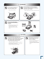
! Warning
Prohibitions
Do not place anything on
top of the heater cover.
Prohibitions
Doing so may result in fire.
Prohibitions
Do not attempt to measure samples
that may undergo dangerous chemical
reactions when heated.
Doing so may result in an explosion or release of toxic gas.
Do not place flammable
materials near the moisture
analyzer.
Some parts of the moisture analyzer
become extremely hot during
operation and could cause a fire
if flammable materials are placed
nearby.
! Caution
Prohibitions
Do not touch the heat-dispersing
component of the heater cover or sample
pan with your bare hands during and
immediately after measurement.
Doing so may result in burn injury.
This moisture analyzer is extremely hot during and
immediately after measurement.
When touching the moisture analyzer, only use the
specified control knobs and accessories.
Prohibitions
Do not place any non-heat
resistant objects near the
moisture analyzer.
Some parts of the moisture analyzer
become extremely hot during
operation and could lead to damage
or deformation of non-heat resistant
objects.
! Caution
Do not use the moisture analyzer in
the following locations:
Prohibitions
Prohibitions
Doing so may result in a malfunction.
• Where there is an air flow (near an airconditioner, air vent, door, window, etc.)
• Where temperatures change markedly
• Where vibrations occur
• In an area exposed to direct sunlight
• Where corrosive or inflammable gases are
present
• Where dust, electromagnetic waves, or
magnetic fields are present
Do not use the moisture
analyzer as a proof of
transaction.
Handle the moisture analyzer carefully.
Instructions
The law does not allow the moisture
analyzer to be used for proof
of transaction such as medical
preparation.
Instructions
The moisture analyzer is a precision device. Subjecting
it to impact may result in a malfunction.
When moving the moisture analyzer main unit, securely
hold it with both your hands.
If long-term storage is required, use the original
package box to pack the product.
Place the moisture analyzer
on a rigid, stable, and flat
table, or on the floor in the
room.
Placing the moisture analyzer on an
unstable surface may cause personal
injury or a malfunction.
Secure a sufficient space for your
measurement work in consideration
of the total weight of measuring
objects and the moisture analyzer
loaded on the installation location.
Prohibitions
Only connect peripherals that have been
specified by us to the connector of the
moisture analyzer.
Connecting other peripherals may cause abnormal
operation.
To prevent problems, be sure to connect peripherals
using the procedure specified in this instruction
manual.
After a power failure, turn
the power switch on.
Instructions
If a power failure occurs, the power is
automatically turned off. See "Turning
the Power On" (^ Page 38) to
restore operation.
Instructions
If an abnormal situation occurs (for
example, a burning odor is smelt), remove
the power cable immediately.
If you continue operating the device in an abnormal
situation, fire or electric shock may result.
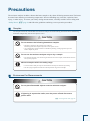
Precautions
The moisture analyzer includes a heater that heats samples to dry them off during measurement. The heater
becomes hotter than the preset heating temperature. Incorrect handling may cause fire, explosion, burn
injury, or other injury. To ensure your safety during measurements, carefully read this section along with
"Safety Notes", (^ page 6) and follow the guidelines outlining correct operation procedures.
n
Samples
The samples measured with the MOC63u moisture analyzer are heated during the measurement. Measuring
hazardous samples may lead to burn injuries or fire.
! Caution
Do not measure the following hazardous samples.
Prohibitions
•
•
Samples in which the characteristics are unknown.
Measuring hazardous samples may lead to burn injuries or fire.
Any sample whose surface hardens or solidifies by heating, causing high inner pressure.
Such a sample may burst.
Do not use the moisture analyzer only to dry a sample.
Prohibitions
•
The moisture analyzer is for measuring the moisture level of a sample, and should not be used
for any other purposes.
Measure samples within the safety range.
Instructions
n
•
•
Use the moisture analyzer only for measurements that vaporize moisture by heating.
Set the drying temperature within the safe temperature range of each sample.
Environment for Measurements
! Caution
Do not place flammable objects near the moisture analyzer.
Prohibitions
Instructions
If lightning is expected to strike, turn the power off and disconnect
power cable.
^ "Turning Power Off", page 50
n
Handling the Moisture Analyzer During and Immediately after
Measurement
! Caution
Install the parts correctly
Instructions
Install the sample pan and pan supporter correctly.
^ "Installing Parts", page 35
Do not touch the sample pan and surrounding parts with bare hands
during or immediately after measurement.
Prohibitions
n
The sample pan and surrounding parts become extremely hot immediately after measurement.
Be sufficiently careful so as not to suffer a burn injury.
• Be sure to use the Sample pan handler when removing the sample pan.
• Never touch any metal parts of the heater or surrounding parts when removing the sample
pan. Otherwise, burn injuries may result.
Parts that Become Hot During and Immediately after Measurement
! Caution
Do not touch the shaded areas during and immediately after
measurement.
Prohibitions
10
The shaded areas in the following figure become extremely hot. Only touch the round marks
when operating.
n
Additional Notes
! Caution
When the device will not be used for a long period of time, turn the
power off and disconnect the power cable.
Instructions
^ "Turning Power Off", page 50
After a power failure, turn the power switch on.
Instructions
If a power failure occurs, the power is automatically turned off. Turn the power switch off once,
then turn it on again.
^ "Turning Power Off", page 50
^ "Turning the Power On", page 38
11
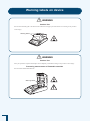
Warning labels on device
! Warning
Caution. Hot
Do not touch the black grill or the observation window on the upper part of the heater cover. Doing so may result in
a burn injury.
Warning labels
! Warning
Caution. Hot
Start your operation only after heated parts have completely cooled down. Doing so may result in a burn injury.
Preventing measurement of flammable materials
Do not measure flammable materials.
Warning labels
12
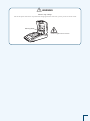
! Warning
Caution. High voltage
Pull out the power cable from a receptacle when changing the heater. Otherwise, you may receive an electric shock.
Warning labels
* When the glass case is removed
13
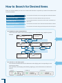
How to Search for Desired Items
There are various methods you can use to search for the function or operation you want to learn about in this
instruction manual.
"Cover Page Index"
You can search for the item on the cover page of the instruction manual.
"What You Can Do", page 4
You can search for the item based on what you want to do.
"Menu Map", page 115
You can quickly search the menu item for the function or procedure you
want to use.
"Table of Contents", page 20
You can search for the item in the instruction manual’s table of contents.
"Index", page 118
You can search for the item using a previously-known name or keyword.
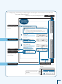
u Notation for menu manipulations
In the instruction manual, some menu manipulations are indicated using simplified symbols.
Example:
Information shown
on the display
Press
in the standby state to
select the menu item
Menu manipulation
flow
Press
to move to the
next item in the menu
Press
User's operation or
supplement
Select the numeric
value or setting
to accept the
setting or selected item
u Indication on the display panel
The instruction manual describes the indication on the display panel corresponding to each
operating procedure.
The operations of the display panel (flashing, lighting up, and confirmation) are indicated as
follows:
Flashing
•
// /
////
////
•
! ! !0.0!0!0
///
14
Lighting up
! ! !0.0!0!0
•
Confirmation
! ! !0.0!0!0
u Sample page ( The following is a sample page to show the layout of this document. The content does
not provide actual operations.)
Linked to the cover page index (right pages only)
Index
Explanation of terms
Describe terms used for
MOC63u.
Menu operation
Reference
Notes
The following information
will help you to use the
device correctly.
Continued on next page
Depiction of the display
The following appears on the top of the
next page.
The title of the previous page
is shown.
15
After-Sales Service
If this product does not operate normally, follow the guidelines in "Troubleshooting Guide" (^ P. 110) to
analyze and manage the problem.
If the problem still persists, or a symptom occurs presumably caused by another failure, contact our service
representative (details on back cover).
Supply of Parts
Repair parts for this product shall be kept for a period of seven years after this product is discontinued.
Please note that, after the above-mentioned period, a requested spare part may not be able to be supplied.
As exceptions, non-genuine repair parts shall be supplied during the period determined by the relevant
manufacturer.
16
MEMO
17
Action for Environment (WEEE)
To all user of Shimadzu equipment in the European Union:
Equipment marked with this symbol indicates that it was sold on or after 13th August 2005,
which means it should not be disposed of with general household waste. Note that our equipment
is for industrial/professional use only.
Contact Shimadzu service representative when the equipment has reached the
end of its life.
They will advise you regarding the equipment take-back.
With your co-operation we are aiming to reduce contamination
from waste electronic and electrical equipment and preserve natural
resource through re-use and recycling.
Do not hesitate to ask Shimadzu service representative, if you require
further information.
WEEE Mark
18
MEMO
19
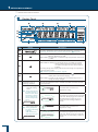
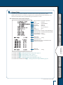
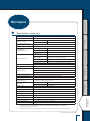
Table of Contents
Table of Contents
Introduction. . . . . . . . . . . . . . . . . . . . . . . . . . . . . . . . . . . . . . . . . . . . . . 3
What You Can Do. . . . . . . . . . . . . . . . . . . . . . . . . . . . . . . . . . . . . . . . . 4
Safety Notes Be sure to follow the safety guidelines . . . . . . . . . . . . . . 6
Precautions. . . . . . . . . . . . . . . . . . . . . . . . . . . . . . . . . . . . . . . . . . . . . . 9
How to Search for Desired Items. . . . . . . . . . . . . . . . . . . . . . . . . . . . . 14
After-Sales Service. . . . . . . . . . . . . . . . . . . . . . . . . . . . . . . . . . . . . . . 16
Supply of Parts . . . . . . . . . . . . . . . . . . . . . . . . . . . . . . . . . . . . . . . . . . 16
Action for Environment (WEEE) . . . . . . . . . . . . . . . . . . . . . . . . . . . . . 18
Table of Contents. . . . . . . . . . . . . . . . . . . . . . . . . . . . . . . . . . . . . . . . 20
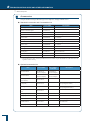
1 Before Measurement
24
Checking Package Contents. . . . . . . . . . . . . . . . . . . . . . . . . . . . . . . . 24
Names and Functions of Parts . . . . . . . . . . . . . . . . . . . . . . . . . . . . . . 25
■ Main Unit . . . . . . . . . . . . . . . . . . . . . . . . . . . . . . . . . . . . . . . . . . . . . . . . . . . . . . . . . . . 25
■ Keyboard . . . . . . . . . . . . . . . . . . . . . . . . . . . . . . . . . . . . . . . . . . . . . . . . . . . . . . . . . . . 27
■ Display Panel. . . . . . . . . . . . . . . . . . . . . . . . . . . . . . . . . . . . . . . . . . . . . . . . . . . . . . . . 28
Installation. . . . . . . . . . . . . . . . . . . . . . . . . . . . . . . . . . . . . . . . . . . . . . 32
■ Determining Installation Location. . . . . . . . . . . . . . . . . . . . . . . . . . . . . . . . . . . . . . . . . 32
■ Installing Parts. . . . . . . . . . . . . . . . . . . . . . . . . . . . . . . . . . . . . . . . . . . . . . . . . . . . . . . 35
■ Adjusting the Level of the Moisture Analyzer. . . . . . . . . . . . . . . . . . . . . . . . . . . . . . . . 36
Preparing for Measurement. . . . . . . . . . . . . . . . . . . . . . . . . . . . . . . . . 38
■ Turning the Power On . . . . . . . . . . . . . . . . . . . . . . . . . . . . . . . . . . . . . . . . . . . . . . . . . 38
■ The Span Calibration after Installing the Moisture Analyzer. . . . . . . . . . . . . . . . . . . . 40
Menu. . . . . . . . . . . . . . . . . . . . . . . . . . . . . . . . . . . . . . . . . . . . . . . . . . 42
■ How to Use the Menu. . . . . . . . . . . . . . . . . . . . . . . . . . . . . . . . . . . . . . . . . . . . . . . . . . 42
■ How to Use the Menu Map. . . . . . . . . . . . . . . . . . . . . . . . . . . . . . . . . . . . . . . . . . . . . . 42
■ How to Enter Data . . . . . . . . . . . . . . . . . . . . . . . . . . . . . . . . . . . . . . . . . . . . . . . . . . . . 43
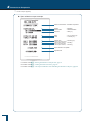
2 Measure
44
Measuring Moisture Content. . . . . . . . . . . . . . . . . . . . . . . . . . . . . . . . 44
■ To Obtain the Best Results . . . . . . . . . . . . . . . . . . . . . . . . . . . . . . . . . . . . . . . . . . . . . 47
Aborting Measurement . . . . . . . . . . . . . . . . . . . . . . . . . . . . . . . . . . . . 48
20
After Measurement . . . . . . . . . . . . . . . . . . . . . . . . . . . . . . . . . . . . . . . 49
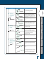
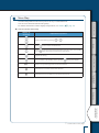
3 Detailed Measurement
Before Measurement
Turning Power Off. . . . . . . . . . . . . . . . . . . . . . . . . . . . . . . . . . . . . . . . 50
52
Setting Measuring Conditions. . . . . . . . . . . . . . . . . . . . . . . . . . . . . . . 52
Measure ■ Selecting the Measurement Condition Program No.. . . . . . . . . . . . . . . . . . . . . . . . . . 52
■ Setting Temperature and the Amount of Change in Moisture Content (∆M) as Measurement Conditions (AUTO: Standard drying automatic ending mode). . . . . . . 53
■ Setting Temperature and Time as Measuring Conditions (TIME: Standard drying timed ending mode). . . . . . . . . . . . . . . . . . . . . . . . . . . . . . . . 55
■ Measuring Samples by Raising Temperature Rapidly (RAPID: Rapid drying mode). . . . . . . . . . . . . . . . . . . . . . . . . . . . . . . . . . . . . . . . . . . . 56
Detailed Measurement
■ Measuring Samples by Raising Temperature Gradually (SLOW: Slow drying mode) . . . . . . . . . . . . . . . . . . . . . . . . . . . . . . . . . . . . . . . . . . . . . 58
■ Measuring Samples by Setting Temperature Step by Step (STEP: Stepped drying mode). . . . . . . . . . . . . . . . . . . . . . . . . . . . . . . . . . . . . . . . . . . 60
Changing Moisture Analyzer Settings. . . . . . . . . . . . . . . . . . . . . . . . . 63
■ Setting the Measurement Standard. . . . . . . . . . . . . . . . . . . . . . . . . . . . . . . . . . . . . . . 63
■ Setting the Method to Start Measurement. . . . . . . . . . . . . . . . . . . . . . . . . . . . . . . . . . 66
Connection to Peripherals
■ Setting Sample Codes. . . . . . . . . . . . . . . . . . . . . . . . . . . . . . . . . . . . . . . . . . . . . . . . . 67
■ Setting the Date and Time. . . . . . . . . . . . . . . . . . . . . . . . . . . . . . . . . . . . . . . . . . . . . . 68
■ Restricting the Menu Display. . . . . . . . . . . . . . . . . . . . . . . . . . . . . . . . . . . . . . . . . . . . 69
■ Setting the Password. . . . . . . . . . . . . . . . . . . . . . . . . . . . . . . . . . . . . . . . . . . . . . . . . . 70
■ Setting the Moisture Analyzer ID. . . . . . . . . . . . . . . . . . . . . . . . . . . . . . . . . . . . . . . . . 72
Calibrating Moisture Analyzer. . . . . . . . . . . . . . . . . . . . . . . . . . . . . . . 73
Maintenance ■ Span Calibration. . . . . . . . . . . . . . . . . . . . . . . . . . . . . . . . . . . . . . . . . . . . . . . . . . . . . . 73
■ Calibrating the Temperature (Option). . . . . . . . . . . . . . . . . . . . . . . . . . . . . . . . . . . . . . 73
■ Output of calibration record. . . . . . . . . . . . . . . . . . . . . . . . . . . . . . . . . . . . . . . . . . . . . 77
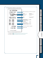
4 Connection to Peripherals
78
Troubleshooting Guide and Other Information
When Connecting MOC63u to Peripheral Devices. . . . . . . . . . . . . . . 78
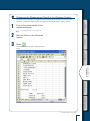
Using Windows Direct Function. . . . . . . . . . . . . . . . . . . . . . . . . . . . . . 79
■ Enable the Windows Direct Function. . . . . . . . . . . . . . . . . . . . . . . . . . . . . . . . . . . . . . 79
■ Connecting the Windows System and the Moisture Analyzer. . . . . . . . . . . . . . . . . . . 81
■ Displaying the Measurement Result in the Windows System. . . . . . . . . . . . . . . . . . . 83
■ If the Windows Direct Function does not Work Well . . . . . . . . . . . . . . . . . . . . . . . . . . 84
21
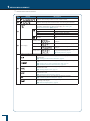
Control Moisture Analyzer from PC. . . . . . . . . . . . . . . . . . . . . . . . . . . 85
■ Setup and Use of the Communication Tool. . . . . . . . . . . . . . . . . . . . . . . . . . . . . . . . . 85
■ How to Use the Command Codes. . . . . . . . . . . . . . . . . . . . . . . . . . . . . . . . . . . . . . . . 88
■ Command Code List . . . . . . . . . . . . . . . . . . . . . . . . . . . . . . . . . . . . . . . . . . . . . . . . . . 89
■ Cable Tie . . . . . . . . . . . . . . . . . . . . . . . . . . . . . . . . . . . . . . . . . . . . . . . . . . . . . . . . . . . 90
Printer Output (Option). . . . . . . . . . . . . . . . . . . . . . . . . . . . . . . . . . . . . 91
■ Connecting a Dedicated Printer. . . . . . . . . . . . . . . . . . . . . . . . . . . . . . . . . . . . . . . . . . 91
■ Setting the Printer Output Method. . . . . . . . . . . . . . . . . . . . . . . . . . . . . . . . . . . . . . . . 92
■ Setting a Measurement Data Printout Timing . . . . . . . . . . . . . . . . . . . . . . . . . . . . . . . 92
■ Printing Stored Measurement Data. . . . . . . . . . . . . . . . . . . . . . . . . . . . . . . . . . . . . . . 93
■ Outputting the Moisture Analyzer Settings from a Printer. . . . . . . . . . . . . . . . . . . . . . 94
■ Output Data . . . . . . . . . . . . . . . . . . . . . . . . . . . . . . . . . . . . . . . . . . . . . . . . . . . . . . . . . 95
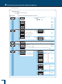
5 Maintenance
98
Maintenance of Moisture Analyzer . . . . . . . . . . . . . . . . . . . . . . . . . . . 98
■ Removing the Glass Case. . . . . . . . . . . . . . . . . . . . . . . . . . . . . . . . . . . . . . . . . . . . . . 99
■ Installing the Glass Case. . . . . . . . . . . . . . . . . . . . . . . . . . . . . . . . . . . . . . . . . . . . . . 101
Replacing Heater. . . . . . . . . . . . . . . . . . . . . . . . . . . . . . . . . . . . . . . . 102
Replacing Fuses . . . . . . . . . . . . . . . . . . . . . . . . . . . . . . . . . . . . . . . . 104
Clearing Measurement Data from Memory. . . . . . . . . . . . . . . . . . . . 105
Initializing Moisture Analyzer Settings. . . . . . . . . . . . . . . . . . . . . . . . 106
Inspection . . . . . . . . . . . . . . . . . . . . . . . . . . . . . . . . . . . . . . . . . . . . . 107
■ Routine Inspection. . . . . . . . . . . . . . . . . . . . . . . . . . . . . . . . . . . . . . . . . . . . . . . . . . . 107
■ Periodic Inspection. . . . . . . . . . . . . . . . . . . . . . . . . . . . . . . . . . . . . . . . . . . . . . . . . . . 108
6 Troubleshooting Guide and Other Information 110
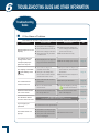
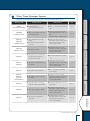
Troubleshooting Guide. . . . . . . . . . . . . . . . . . . . . . . . . . . . . . . . . . . . 110
■ If You Have a Problem. . . . . . . . . . . . . . . . . . . . . . . . . . . . . . . . . . . . . . . . . . . . . . . . 110
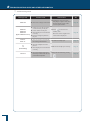
■ When These Messages Appear…. . . . . . . . . . . . . . . . . . . . . . . . . . . . . . . . . . . . . . . 111
When Required. . . . . . . . . . . . . . . . . . . . . . . . . . . . . . . . . . . . . . . . . 113
■ Specifications (main unit). . . . . . . . . . . . . . . . . . . . . . . . . . . . . . . . . . . . . . . . . . . . . . 113
■ Accessories. . . . . . . . . . . . . . . . . . . . . . . . . . . . . . . . . . . . . . . . . . . . . . . . . . . . . . . . 114
■ Menu Map . . . . . . . . . . . . . . . . . . . . . . . . . . . . . . . . . . . . . . . . . . . . . . . . . . . . . . . . . 115
Index. . . . . . . . . . . . . . . . . . . . . . . . . . . . . . . . . . . . . . . . . . . . . . . . . 118
22
MEMO
Before Measurement
Measure Detailed Measurement
Connection to Peripherals
Maintenance Troubleshooting Guide and Other Information
23
1 Before Measurement
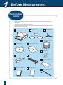
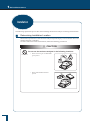
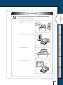
Checking Package
Contents
Be sure to check that the package contains all of the following parts and that all parts are
undamaged.
A number shown in [ ] indicates a quantity.
If you find that any of the parts are missing, damaged, or deformed, contact an authorized
Shimadzu sales representative.
Moisture Analyzer unit [1]
Sample pan [3]
Pan supporter [1]
Aluminum pan (disposal) [50]
Windbreak [1]
Heater insulation plate [1]
Spare fuse [2]
Sample pan handler [1]
Power cable [1]
Display protect cover [1]
Instruction manual [1]
Menu map sheet [1]
Hexagonal wrench SB2.5 [1]
24
Before Measurement
Names and
Functions of Parts
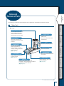
The following explains the individual parts and components of the MOC63u moisture analyzer.
n
Main Unit
Measure
u Front
Observation window
You can observe the condition
of the sample (object) even
when the heater is turned on
and the heater cover is closed.
Set the pan supporter and
sample pan on this, then place
an object.
A heater is included in the
heater cover.
Close the heater cover before
measurement.
Detailed Measurement
Pan
Heater cover
Heater
Used to dry samples (objects).
Display panel
Level gauge
Used to adjust the level of the
moisture analyzer. (^ page 36)
Used for menu manipulation, tare
cancellation, setting measuring conditions
or functions, or span calibration.
(^ page 27)
Detects temperature.
Product label
Shows the model name and the
unit number.
Level screws
Used to adjust the level of the
moisture analyzer.
(^ page 36)
Maintenance
Keyboard
Temperature sensor
Connection to Peripherals
Displays measurement
results, information for
function settings, functions
currently running, errors, and
other information. (^ page 28)
Troubleshooting Guide and Other Information
s
Continued on next page
25
1 Before Measurement
s
Names and Functions of Parts
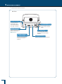
u Rear
Kensington security slot
A mounting hole for
anti-theft key. This
slot complies with the
Kensington standard.
DATA I/O connector
Used to connect a printer (EP-80, EP-90, etc.) (^ page 91)
RS-232C connector
(9-pin socket)
Used to connect the main
unit to a PC via serial
interface.
26
Fuse holder
If a fuse breaks, replace
it with a fuse in this fuse
holder.
Power inlet
Connect the power cable to
supply power to the moisture
analyzer.
USB connector
Used to connect the main unit to a PC.
n
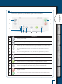
Keyboard
The following explains the keys placed on the top of the moisture analyzer.
a
2
0
Before Measurement
1
Measure
3
4
6
Key
7
8
9
Description
Detailed Measurement
No.
5
Calls the menu during the standby state (measurement display).
3
Returns to the upper level of the menu tree.
Shifts the digit to the left when the date and time, password, sample code, or ID is entered.
4
Selects the menu item.
The setting value increases when the code, date and time, temperature, or password is
entered.
5
Selects the menu item.
Decreases the setting value when the code, date and time, temperature, or password is
entered.
6
Moves to the lower level of the menu tree.
Shifts the digit to the right when the date and time, password, sample code, or ID is entered.
7
Applies the setting.
8
Clears the display to zero (0) when a sample pan is placed and this key is pressed.
9
Returns to the menu during setting. Press this key again to return to the standby state
(measurement display).
Returns to the standby state (measurement display) when the measurement ends.
Releases the error when an error occurs.
0
Stops the measurement.
a
Use this function when "Manual mode" is selected for the method to start measurement .
s
Troubleshooting Guide and Other Information
2
Maintenance
Turns the power on or off.
Connection to Peripherals
1
Continued on next page
27
1 Before Measurement
s
Names and Functions of Parts
n
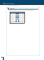
Display Panel
1
6
7
8
2
3
4
5
Display
Description
///
The measurement is started. The
temperature is rising.
/
/ /
/ / / // / /
/ /
///
//
////// ////
//
//
The measuring temperature has reached the
preset level. The drying process continues
until ∆M (moisture change rate per 30
seconds) set as the ending condition is
reached.
The measurement is started. The
temperature is rising.
////
TIME: Standard drying
timed ending mode
^ "Setting Temperature
and Time as Measuring
Conditions
(TIME: Standard drying
timed ending mode)", page 55
//
////
AUTO: Standard drying
automatic ending
mode
^ "Setting Temperature and
the Amount of Change in
Moisture Content (∆M) as
Measurement Conditions
(AUTO: Standard drying
automatic ending mode)",
page 53
//
The setup mode and
measurement state of
measuring conditions
When shown: T
he measurement is completed. Press
to return to the
standby state (measurement display).
When hidden: Currently in the standby state or measurement process, or
settings are being changed.
Displays the setup mode and measurement state of measuring conditions.
The current measurement state is available from flash of the bar encircled
by the dotted line.
//
4
//
3
/ / / / / /
/ /
/
2
//////////
28
a
Indicates the program No. (0 to 9) currently selected.
For further information on how to select the program No., see steps 1 to 3 of
"Selecting the Measurement Condition Program No." (^ page 52).
When shown: C
ommunicates with other equipment (printer, PC, etc.) via
RS-232C, DATA I/O, or USB.
When hidden: No equipment is communicating using RS-232C, DATA I/O,
or USB.
When shown: T
he measured value is stable.
When hidden or flashing: T he measured value is not stable. Re-examine
the environment where the moisture analyzer
is installed, and adjust the level of the moisture
analyzer.
* Flashing during menu display indicates that the setting corresponding to
the menu item is valid.
^ "Measuring Moisture Content", page 44
1
5
0
//
No.
9
The measuring temperature has reached the
preset level. The drying process continues
until the time set as the ending condition is
reached.
Display
Description
//
///
// ///
Continues drying at the maximum
temperature after the temperature has
reached the maximum and it also reaches ∆
M (amount of change in moisture content
per 30 seconds) set as the rapid drying
mode condition.
The temperature is dropping to the preset
level.
///
/
/
/////
//
The measuring temperature has reached the
preset level. The drying process continues
until ∆M (moisture change rate per 30
seconds) set as the ending condition is
reached.
//
///
//
/ /
The measurement is started. The
temperature is rising.
/////
//
//
Detailed Measurement
// //
///////
//
////
5
//
The set first step temperature is reached.
//
///
// ///
Connection to Peripherals
The measurement is started. The
temperature is rising.
////
///
The measuring temperature has reached the
preset level. The drying process continues
until ∆M (moisture change rate per 30
seconds) or the time set as the ending
condition is reached.
/ ///
//
Measure
// ///
/////
/////
//
//////
///
SLOW: Slow drying mode
^ "Measuring
Samples by Raising
Temperature
Gradually
(SLOW: Slow drying
mode)", page 58
Before Measurement
The measurement is started. The
temperature is rising.
//
RAPID: Rapid drying mode
^ "Measuring
Samples by Raising
Temperature Rapidly
(RAPID: Rapid
drying mode)",
page 56
//
///////
///////
No.
The temperature is rising to the second step
level.
The set second step temperature or ∆M
(moisture change rate per 30 seconds) is
reached.
//
//
///
/////
//
////
///
Maintenance
// ///
//
//
///
// ///
Troubleshooting Guide and Other Information
The temperature is rising to the third step
level.
/////
///
/////
//
////
STEP: Stepped drying mode
^ "Measuring
Samples by Setting
Temperature Step by
Step (STEP: Stepped
drying mode)",
page 60
The set third step temperature is reached.
The drying process continues until the
time or ∆M (moisture change rate per 30
seconds) set as the ending condition is
reached.
s
Continued on next page
29
1 Before Measurement
s
Names and Functions of Parts
No.
Display
Description
6
Indicates the time elapsed after the start of measurement.
7
Indicates the temperature inside the heater cover during measurement.
Indicates the measurement result display currently selected.
For further information on changing the display, see "Setting the
Measurement Standard" (^ page 63).
M/W
Moisture content (Wet Base)
D/W
Dry content (Wet Base)
M/D
Moisture content (Dry Base)
W/D
Dry content (Dry Base)
8
GRAM
9
0
30
Main display
Mass
Standby state
The measured value by the balance is
displayed.
Measuring
The moisture measurement is displayed.
Menu
The menu and the setting items are
displayed.
Ready status
The moisture analyzer is in the energy
saving mode and ready for use.
^ "Ready status is", page 50
Displays the following menu item currently selected.
The selected menu item is for setting the format to display the current
measurement.
^ "Setting the Measurement Standard", page 63
The selected menu item is for setting the method to output data to a printer
or PC.
^ "Setup and Use of the Communication Tool", page 85
^ "Enable the Windows Direct Function", page 79
The selected menu item is for setting sample codes to be output as a
measurement result.
^ "Setting Sample Codes", page 67
The selected menu item is for setting the date and time to be output as a
measurement result.
^ "Setting the Date and Time", page 68
The selected menu item is for calibrating the moisture analyzer.
^ "Calibrating Moisture Analyzer", page 73
The selected menu item is for setting the output of measurement results and
the timing of the output.
^ "Printer Output (Option)", page 91
No.
Display
Description
Lower
When flashing: T he heater is running and
the measurement is in
process.
When hidden: The heater is not running.
When shown: A sample is placed on the
sample pan.
When flashing: A sample is not placed on
the sample pan. Place a
sample on the sample pan.
When hidden: A sample is not placed on the
sample pan.
When shown: A sample is placed on the
sample pan.
When flashing: Cancel the tare of the
sample pan.
When hidden: A sample pan is not placed.
When turned on: T he pan supporter is
installed.
Blinking: The pan supporter is not installed.
Measure
a
Before Measurement
Indicates the moisture analyzer status.
Upper
When shown: The heater cover is open.
When flashing: You must close the heater
cover currently open.
When hidden: The heater cover is closed.
Middle
When shown: The heater cover is closed.
When hidden: The heater cover is open.
Detailed Measurement
Connection to Peripherals
Maintenance
Troubleshooting Guide and Other Information
31
1 Before Measurement
Installation
The following explains the process flow from installing the moisture analyzer to starting measurements.
n
Determining Installation Location
Measurement performance of the moisture analyzer depends largely on environments where the
moisture analyzer is installed.
To ensure safe and accurate measurements, follow the following precautions.
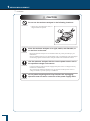
! Caution
Do not use the moisture analyzer in the following locations:
Prohibitions
32
•
Where corrosive gas or inflammable
gas is present
•
Where a flammable material is
present
! Caution
Before Measurement
Do not use the moisture analyzer in the following locations:
Prohibitions
The measurement result may be incorrect.
•
Where there is an air flow (near an airconditioner, air vent, door, window,
etc.)
Measure
Where temperature changes extremely
•
Where vibration occurs
•
Exposed to direct sunlight
Detailed Measurement
•
Connection to Peripherals
Maintenance
Troubleshooting Guide and Other Information
s
Continued on next page
33
1 Before Measurement
s
Installation
! Caution
Do not use the moisture analyzer in the following locations:
Prohibitions
•
Where dust, electromagnetic waves, or
magnetic fields are present
Place the moisture analyzer on a rigid, stable, and flat table, or
on the floor in the room.
Instructions
Placing the moisture analyzer on an unstable surface may cause personal injury or a
malfunction.
Secure a sufficient space for your measurement work in consideration of the total weight
of measuring objects and the moisture analyzer loaded on the installation location.
Use the moisture analyzer with the correct power source and in
the specified voltage environment.
Instructions
Using the moisture analyzer with an inappropriate power source or voltage level may
result in fire or malfunction.
Also note that the optimal performance may not be achieved when power source or
voltage is unstable, or power capacity is insufficient.
Do not palace anything which may interfere the unplugging
operation near the mains connector of the power supply cable.
Instructions
34
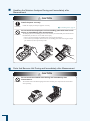
n
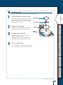
Installing Parts
Take the following steps to install the moisture analyzer parts.
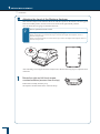
Install the heater insulation plate.
Install the heater insulation plate onto the case.
Align the hole in the heater insulate plate with
that in the pan supporter, and place the heater
insulation plate on the case.
3
Align u on the case with u on the windbreak,
and place them on the heater insulation plate.
Install the pan supporter.
Pan supporter
Windbreak
Heater
insulation plate
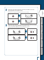
Place the pan supporter on the axis of the
moisture analyzer main unit.
Align u on the pan supporter with u on the
windbreak, and insert them onto the bottom.
Detailed Measurement
4
Install the Windbreak.
Sample pan
Measure
2
Before Measurement
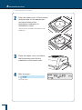
1
Place a sample pan.
Place a sample pan on the pan supporter so that
brim of the supporter can secure the sample pan.
Connection to Peripherals
Maintenance
Troubleshooting Guide and Other Information
s
Continued on next page
35
1 Before Measurement
s
Installation
n
Adjusting the Level of the Moisture Analyzer
This moisture analyzer unit maintains the level with three points on the bottom: One fixing point
at the rear middle position, and two level screws on the front right and left positions.
You can check the level gauge to determine the level.
*
How to operate the level screws
The height of the level screws can be changed by rotating it.
Rotate it clockwise (as seen from the top) to increase the height of the adjuster, and so is
moisture analyzer unit.
Rotate it counterclockwise (as seen from the top) to reduce the height of the adjuster, and so is
moisture analyzer unit.
Level gauge
After installing or moving the moisture analyzer unit, take the following steps to adjust the level
of the unit.
1
Rotate the right and left level screws counterclockwise (as seen from the top).
Rotate them carefully until they stop.
The adjusters shrink and the front of the unit drops.
36
Rotate the right and left adjusters until the air bubble in the level
gauge appears at the lateral center.
Before Measurement
2
At this step, you can neglect the longitudinal position of the air bubble.
Rotate the front right adjuster clockwise.
When the air bubble is on the left
Measure
Rotate the front left adjuster clockwise.
When the air bubble is on the right
Rotate the right and left adjusters at the same time until the air bubble
in the level gauge appears at the longitudinal center.
Detailed Measurement
3
Adjust them until the air bubble appears at the center of the red circle.
When you rotate two level screws clockwise at the same
time...
Connection to Peripherals
When you rotate two level screws counterclockwise at the
same time...
The air bubble moves forward.
The air bubble moves backward.
Maintenance
Troubleshooting Guide and Other Information
37
1 Before Measurement
Preparing for
Measurement
Turn on the power of the moisture analyzer before starting measurement.
^ "Turning the Power On", page 38
When you use the moisture analyzer for the first time, we recommend the span calibration after
installation.
^ "The Span Calibration after Installing the Moisture Analyzer", page 40
n
Turning the Power On
The following explains how to turn the power on.
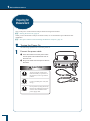
1
Connect the power cable.
1 Insert the female end of the power cable
into the power inlet located at the rear of
the main unit.
2 Plug in the male end of the power cable to
the outlet.
Caution
Instructions
Instructions
Instructions
38
To prevent electric shock and to
maintain stability in operation of
the product, be sure to ground the
product.
Use the specified power cord (10A
rating).
Do not palace anything which may
interfere the unplugging operation
near the mains connector of the
power supply cable.
(*1) The version number is subject to change
without notice.
! ! ! ! ! ! !
Before Measurement
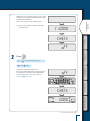
When the power switch is turned on, the version
number (*1) is displayed and the internal system
is checked automatically.
Then, "oFF" appears on the display panel.
!V!1.0!0!0!0!
Measure
! !C!H!E!C!K!
! ! ! ! !F!F!
Detailed Measurement
2
Press
[ FF]
[CHECK]
[(The entire display lights up.)]
[0.000 ]
Connection to Peripherals
The device enters the standby state.
If you start measurement by using the program
No. displayed on the upper left of the display,
proceed to step 4 of "Measuring Moisture
Content" (^ page 44).
! ! ! ! !F!F!
!
Maintenance
! !C!H!E!C!K!
Troubleshooting Guide and Other Information
! ! !0.0!0!0
s
Continued on next page
39
1 Before Measurement
s
Preparing for Measurements
n
The Span Calibration after Installing the Moisture Analyzer
After installing the moisture analyzer, we recommend you warm it up and perform span
calibration to stabilize the moisture analyzer. The span calibration is possible between 10 and 60
grams, however, a 50-gram calibration weight is recommended.
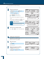
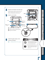
1
2
Turning the power on.
^ "Turning the Power On", page 38
3
Wait for at least one hour (to warm up the moisture analyzer).
To calibrate the sensitivity for precision measurement, the moisture analyzer must be in a stable
state wherever possible. To stabilize the moisture analyzer, we recommend you leave it to the
standby state for at least one hour. This is called "Warming-up".
Start the menu.
[
!P!R! !G!R!M
]
The menu appears.
4
Start the span calibration.
[CAL]
[BAL]
[WAIT]
! ! ! !C!A!L!
[50.000 ]
If [TEMP] is displayed instead of [BAL], press
or
! ! ! !B!A!L
to display [BAL].
/ / / / / / / / / /
/
/ /
/ /
/ / / / / /
/ / / /
//
//
5
Open the heater cover.
40
/ /
! !5!0.0!0!0!
When you use a weight other than
50 grams...
If you use a weight other than the
50-gram one, reset the corresponding
mass by pressing
press
! !5!0.0!0!0!
/ /
/ /
*
/ / / / // / / / /
/
/ /
/ / / / / / / / /
/
/ /
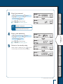
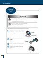
Place a 50-gram calibration weight on the sample pan.
Before Measurement
6
When the mass indication flashes,
place the weight.
. Then,
and place the weight.
Measure
When the weight is placed, the measurement of
50 grams starts.
*
To Calibrate with the heater cover
closed…
// /
! ! !0.0!0!0
/////////
//
The measurement of 0 grams starts.
/////////
//
Connection to Peripherals
Lower the calibration weight when [0.000] starts to flash.
// /
7
Detailed Measurement
Ensure that the glass protect plate
does not come in contact with the
calibration weight when the heater cover
is closed. If it does, open the heater
cover and perform calibration within an
environment without any disturbance
(vibration, wind).
When the mass indication flashes,
remove the weight.
Maintenance
8
Wait until [END] is displayed.
The span calibration ends when [END] is
displayed.
The display returns to BAL after a short period
of time. Press
to enter the standby state.
Troubleshooting Guide and Other Information
You can also calibrate the temperature. For
further information, see "Calibrating the
Temperature (Option)" (^ page 73).
41
1 Before Measurement
Menu
Use the menu to configure measuring conditions for the MOC63u moisture analyzer, or to set the display
and output of its measured values.
n
How to Use the Menu
The following describes how to use the menu.
•
Press
to call up the menu.
•
Press
or
to select the item, and press
to accept the selection.
If a lower level of the menu tree is shown, move to the lower level.
n
•
Press
to move to the lower level.
•
Press
to return to the upper level.
•
To return to the standby state from the menu, press
.
How to Use the Menu Map
The menu map allows the user to conveniently and quickly access menu items.
^ "Menu Map", page 115
42
n
How to Enter Data
Before Measurement
Some menu items such as temperature, time, ∆M (Moisture change rate for 30 seconds), and
password require input of values.
u Key operation
Key
Input data
Operation
Upon date entry
Upon time entry
The value (0 to 9)
increases. If this key
is held down, the
value changes from
9 to 0 and the tenth
digit is incremented.
In the password field:
The display value
changes from 0 to 9
sequentially.
In the ID input field:
Values 0 to 9, a
negative sign (-),
characters A to Z, and
a space are displayed
sequentially.
First and second
digits: Values 0 to 9,
a negative sign (-),
characters A to Z, and
a space are displayed
sequentially.
Third and fourth
digits: The value (3
to 9) increases.
The value increases.
The value decreases.
If this key is held
down, the value
changes from 1 to 0
and the tenth digit is
decremented.
In the password field:
The display value
changes from 9 to 0
sequentially.
In the ID input field:
A space, characters
Z to A, a negative
sign (-), and values
9 to 0 are displayed
sequentially.
First and second
digits: A space,
characters Z to A,
a negative sign
(-), and values 9
to 0 are displayed
sequentially.
Third and fourth
digits: The value
decreases.
The value decreases.
Returns to the
previous setting.
Shifts the active digit
(that is flashing) to
the left by one. Four
digits for a password
or ID.
Shifts the active digit
(that is flashing) to
the left by one. Four
digits for a sample
code.
Shifts the active digit
(that is flashing)
to the left by one.
Specify each of the
year, month, and date
in two digits.
Goes to the next
setting.
Shifts the active digit
(that is flashing) to
the right by one.
Shifts the active digit
(that is flashing) to
the right by one.
Shifts the active digit
(that is flashing) to
the right by one.
Connection to Peripherals
Sample code
Detailed Measurement
Password
ID
Measure
Temperature
Time
∆M
Maintenance
Accepts the entered value.
Troubleshooting Guide and Other Information
43
2 Measure
Measuring
Moisture Content
You can call preset measuring conditions for measurement with the moisture analyzer. When you use the
moisture analyzer for the first time, set measuring conditions. For further information on how to turn the
power on, see "Turning the Power On" (^ Page 38). For details on setting the measuring conditions,
see "Setting Measuring Conditions" (^ Page 52).
The following explains how to start measurement after the standby state.
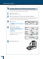
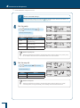
1
Confirm the standby state.
Confirm that the device is in the standby state
(measurement display) as shown in the figure at
right.
Press
to set it to the standby state when
the menu items and measurement results are
displayed on the display panel.
2
! ! !0.0!0!0
Open the heater cover.
Handle
Hold the handle of the heater cover (shown in
figure at right), and carefully open the lid to the
end.
! ! !0.0!0!0
3
44
Place a sample pan.
Place a sample pan on the pan supporter.
Use a sample pan that is kept at room
temperature.
Sample pan
Be sure that (the stability mark) is displayed, and adjust the
zero point.
Check whether the stability mark is
displayed.
[0.000 ]
Before adjusting the zero point, be sure that
the pan supporter and an empty sample pan are
placed.
Before Measurement
4
! ! !0.0!0!0!
^ "Installing Parts", page 35
Measure
Do not expose the moisture analyzer to wind or vibration before adjustment is completed.
What is the zero point adjustment?
An operation that cancels the mass of tare such as sample pan to measure the mass of sample
correctly.
The heater cover during the zero point adjustment
*
After adjusting the zero point.
Detailed Measurement
*
Always be sure that the heater cover is closed when adjusting the zero point.
If the message occurs, press
Connection to Peripherals
Start measurement within thirty minutes after the zero-point adjustment. If you do not
start measurement within thirty minutes, a message (TIM.oUT) occurs in order not to do
unexpected operation.
to return to the standby state (measurement display).
Start measurement promptly after adjusting the zero point.
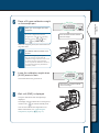
5
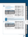
Place a sample (object) on the sample pan.
Maintenance
Be sure to place the sample as flat as possible
on the pan so that heat is applied evenly to the
sample during measurement.
Use a sample pan kept at room temperature.
^ "To Obtain the Best Results", page 47
*
A sample that is less than 0.02 grams cannot be measured.
Troubleshooting Guide and Other Information
! ! !5.0!1!2
A sample that is less than 0.02 grams
may be detected as a balance error.
Place a sample with at least 0.02 grams
on the sample pan.
s
Continued on next page
45
2 Measure
s
Measuring Moisture Content
6
Close the heater cover.
The measurement starts automatically.
*
If the measurement does not start
automatically…
Manual start is set for measurement.
Press
*
to start the measurement.
Switching between automatic and
manual start modes
As the default setting, measurement
start automatically after a sample is
placed and the heater cover is closed.
You can switch the mode to manual
start. ^ "Setting the Method to Start
Measurement", page 66
*
To check the ΔM…
When
is pressed in any
measurement mode, the display
switches and the ΔM value is shown.
Press this key again to return to the
previous display.
! !S!T!A!R!T
! ! ! !0.2!7
What is ΔM?
ΔM is the rate of moisture change after 30 seconds.
^ "Setting Temperature and the Amount of Change in Moisture Content (∆M) as
Measurement Conditions (AUTO: Standard drying automatic ending mode)", page 53
*
7
Do not touch the inside of the heater cover immediately
The heat-dispersing component of the heater cover and the sample pan release heat during and
immediately after the measurement. Do not touch the moisture analyzer with your bare hands.
Check the measurement result.
Short beep sounds indicate that the measurement
is completed. The display panel shows the
measurement result and the measurement
completed indicator ( ). You can output
the measurement result to a printer or PC if
necessary. The factory default setting for the
output results is "FINAL".
^ "Setting a Measurement Data Printout
Timing", page 92
The heater fan stops automatically.
46
! ! ! !0.9!5
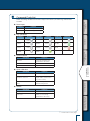
Reset the measurement result.
! ! !4.9!6!4
Before Measurement
8
The water content indicator and measurement
completed indicator relating to the measurement
result disappear, and the mass after drying
process appears.
*
To measure the same sample after
the measurement successively…
Measure
If you switch the mode to manual
start, you can measure successively
by pressing
after resetting the
measurement result.
n
Detailed Measurement
Proceed to "After Measurement", page 49.
To Obtain the Best Results
The following explains how to measure moisture content correctly.
u Precaution for carrying out measurements in succession
Placing a sample on the warmed sample pan may cause moisture from the sample to
evaporate before starting measurement, causing an error in measurement result. Be sure to
use a sample pan kept at room temperature when measuring another samples.
• When measuring samples in succession, keep a constant interval between the measurements
wherever possible. If the temperature inside the moisture analyzer is not stable, errors may
affect the measurement results.
Connection to Peripherals
•
u Quantity and placement of powdered, particulate and viscous sample materials
A sample must be placed on the sample pan flatly. Samples cannot be heated properly if they
are not placed flatly. Placing samples in mounds or in layers of varying thickness may cause
the highest points to be burned, leading to inaccurate measurement results.
• Placing a larger amount of sample flatly can lead to more accurate measurement. However, if
the amount is too large, the surface of the sample may burn before inside is dried out.
• See the following figures to place the appropriate amount of sample flatly.
•
Maintenance
Proper placement
Incorrect placement
Troubleshooting Guide and Other Information
u Measuring liquid samples
•
Depending on the sample, you can reduce the measurement time and improve the
measurement accuracy by using fiberglass (option).
47
2 Measure
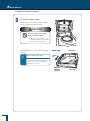
Aborting
Measurement
You can abort the measurement in process.
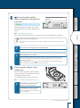
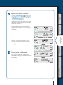
1
Press
during measurement.
[AB RT]
! ! ! !0.9!5
A long beep sound is heard, and "ABoRT"
appears on the display.
! !A!B! !R!T
2
Return to the standby state.
[(Standby state.)]
The moisture analyzer enters the standby state
without saving the measurement result.
When the [STOP] key is pressed again, the
measurement completed indicator is displayed,
the measurement results are stored in the
moisture analyzer, and the device enters the
standby state.
*
Do not touch the moisture analyzer
immediately
The heat-dispersing component of the
heater cover and the sample pan release
heat during and immediately after the
measurement. Do not touch the moisture
analyzer with your bare hands.
The heater fan is still running, and stops after a
short period of time.
Proceed to "After Measurement", page 49.
48
! ! !4.9!6!4
Before Measurement
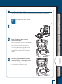
After Measurement
After the measurement of a sample is completed, dispose of the sample and cool off the heater to
prepare for the next measurement.
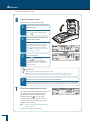
1
Open the heater cover.
Measure
Caution
Prohibitions
Detailed Measurement
2
The heater cover is hot during and
immediately after measurement.
Hold the handle when opening or
closing the heater cover.
Dispose of a sample used for
measurement.
Connection to Peripherals
Hold an edge of the sample pan with the handler
as shown, and remove the sample pan and
dispose of the sample.
The sample pan and the sample are hot. Wait
until they are cooled off.
After the disposal, return the sample pan onto
the pan supporter.
If you used an aluminum pan (disposal), dispose
of it together with the used
sample.
Maintenance
For further information on measuring another
sample in succession, see "Precaution for
carrying out measurements in succession"
(^ page 47).
Prohibitions
Troubleshooting Guide and Other Information
Caution
During and immediately after
measurement, the inside of the
heater cover and the sample pan
is very hot. Use the Sample pan
handler to take out the sample pan.
49
2 Measure
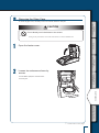
Turning Power Off
The following explains how to turn off the power of the moisture analyzer.
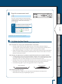
1
Press and hold
until [oFF] appears on the display.
! ! !0.0!0!0!
(at least 0.2 second.)
If you hold down
for about 0.2 second, the
power switch is turned off. "READY" appears
on the panel and the analyzer is ready for use.
To cut the power completely, remove the power
cable.
*
50
Ready status is…
The moisture analyzer is in the energy
saving mode and ready for use.
When the moisture analyzer is in the
ready sate, electricity is supplied and the
analyzer is kept heated even though it is
in the energy saving mode.
! ! ! !F!F! !
! !R!E!A!D!Y
MEMO
Before Measurement
Measure
Detailed Measurement
Connection to Peripherals
Maintenance
Troubleshooting Guide and Other Information
51
3 Detailed Measurement
Setting Measuring
Conditions
There are four types of drying modes (standard drying, rapid drying, slow drying, and stepped drying)
for measurement conditions. There are two types of ending modes (automatic ending and timed ending).
Configure the temperature, time, or ∆M (amount of change in moisture content per 30 seconds) for
all modes. Saving the measuring conditions enables you to call relevant conditions when needed and
measure moisture content based on these conditions. A maximum of 10 measuring conditions can be
saved.
The procedures to set measuring conditions are as follows:
•
Setting Temperature and the Amount of Change in
Moisture Content (∆M) as Measurement Conditions
(AUTO: Standard drying automatic ending mode)
page 53
•
Setting Temperature and Time as Measuring Conditions
(TIME: Standard drying timed ending mode) page 55
•
Measuring Samples by Raising Temperature Rapidly
(RAPID: Rapid drying mode) page 56
Measuring Samples by Raising Temperature Gradually
(SLOW: Slow drying mode) page 58
Measuring Samples by Setting Temperature Step by Step
(STEP: Stepped drying mode) page 60
•
•
*
n
To protect the heater
You cannot use the heater for more than one hour with the temperature set above 180°C.
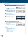
Selecting the Measurement Condition Program No.
Select the program No. to store measurement conditions.
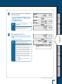
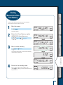
1
Start the menu.
[
]
The menu opens.
52
!P!R! !G!R!M!
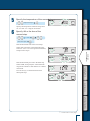
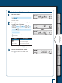
Select the program No. to save measuring conditions.
[PRG-
]
[
///
]
////
]-[
[S1 XXX]
! ! ! !N! .2!
///
Measure
! ! ! !N! .1!
////
////
(XXX indicates setting of the program No.)
///
The program No. is changed.
Press
to return to the standby state.
////
program No. currently selected.)
[
!P!R!G!-!N! !
] (n indicates the
///
Before Measurement
2
! ! !0.0!0!0
Detailed Measurement
n
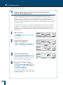
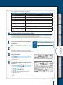
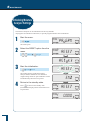
Setting Temperature and the Amount of Change in Moisture
Content (∆M) as Measurement Conditions (AUTO: Standard drying automatic ending mode)
1
Start the menu.
[
Connection to Peripherals
Standard drying automatic ending mode dries a sample at the set temperature and, when the
amount of change in moisture content drops below the set value, terminates the measurement
automatically. Set the drying temperature and the ending condition of moisture change rate per
30 seconds.
When GRAM is selected for measurement standard (^ Page 63), specify ∆M for Moisture
Content (Wet Base)
Maintenance
!P!R! !G!R!M!
]
The menu opens.
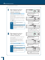
2
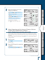
Select [AUTO] mode for measuring
conditions.
[PRG-
]
!P!R!G!-!N!
[AUTO]
Troubleshooting Guide and Other Information
! ! !A!U!T!
s
Continued on next page
53
3 Detailed Measurement
Setting Measuring Conditions
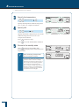
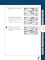
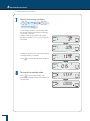
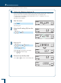
5
Press
to return to step 3.
Press
to save the measurement conditions.
Return to the standby state.
Press
to return to the standby state
(measurement display) where measurement can
be performed.
*
When measuring a sample that
has low moisture content...
If you use the standard automatic drying
operation mode to measure a sample
that has a low moisture content (0.1% or
less), it may reach the ending condition
at once and your measurement may
fail. To measure a sample that has a low
moisture content, we recommend that
you use the standard drying time mode
as explained on the next page.
54
/ /
/ / / / / /
! ! ! !0.0!5
/ /
/
/
/////
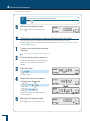
Specify the moisture change rate per 30 seconds
within the range from 0.01 % to 0.1 % in
0.01-percent increments.
/
! ! !A!U!T!
! ! !0.0!0!0
/ /
(∆M input.)
/////
/ / / /
/ /
Specify ∆M.
! ! ! !1!2!0
/ /
4
/////
Specify the temperature within the range from
50 °C to 200 °C in 1-degree increments.
/////
/ / / / / /
/ /
(Temperature input.)
/
/ /
3
Specify the temperature.
/ / / /
/ /
s
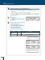
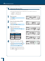
n
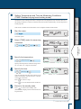
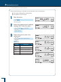
Setting Temperature and Time as Measuring Conditions (TIME: Standard drying timed ending mode)
Before Measurement
Standard dry time ending mode dries a sample at the set temperature and, when the time set as
the ending condition is reached, terminates the measurement automatically. Set the temperature
and drying time.
This mode is suitable for measurements to be completed within a limited time.
1
Start the menu.
[
!P!R! !G!R!M!
]
Measure
The menu opens.
2
Select [TIME] mode for measuring conditions.
[PRG-
]
!P!R!G!-!N!
[TIME]
Detailed Measurement
! ! !T!I!M!E
/ /
/
/
/ /
/ / / /
/ /
/////
Press
!
/ / / / / /
Maintenance
You can set the drying time until 4 hours in one
minute increments, or from 4 hours to 12 hours
in one hour increments.
Press
to return to step 3.
/////
/
/ /
(Time entry.)
to save the measurement conditions.
Return to the standby state.
Press
to return to the standby state
(measurement display) where measurement can
be performed.
! ! !T!I!M!E
Troubleshooting Guide and Other Information
5
/////
Specify the time.
! ! ! !1!2!0
/ /
4
/ / / / / /
Connection to Peripherals
Specify the temperature within the range from
50 °C to 200 °C in 1-degree increments.
/
/ /
(Temperature input.)
/////
/ / / /
/ /
Specify the temperature.
/ /
3
! ! !0.0!0!0
s
Continued on next page
55
3 Detailed Measurement
s
Setting Measuring Conditions
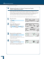
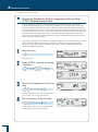
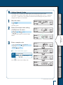
n
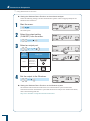
Measuring Samples by Raising Temperature Rapidly (RAPID: Rapid drying mode)
Rapid drying mode raises the temperature rapidly until the amount of change in moisture content
per 30 seconds drops below the set value, then dries a sample at the set temperature. As the
ending condition, you can select either the amount of change in moisture content per 30 seconds
or the time. When the amount of change in moisture content per 30 seconds drops below the set
value, or the time reaches the set value, the measurement terminates automatically. Set
∆M and temperature in rapid drying, and ∆M or time as the ending condition.
This mode is suitable for measuring liquid or other samples that take time to be dried off.
1
Start the menu.
[
!P!R! !G!R!M!
]
The menu opens.
2
Select [RAPID] mode for
measuring conditions.
[PRG-
]
!P!R!G!-!N!
[RAPID]
! !R!A!P!I!D!
/ //
! ! ! ! !0.1!
//
///
56
/ / / / / /
/ /
Specify the temperature within the range from
50 °C to 200 °C in 1-degree increments.
/
! ! ! !1!2!0!
//
(Temperature input.)
////
/ /
Specify the temperature.
//
/ / / /
/ /
//
////
Specify the moisture change rate per 30
seconds within the range from 0.1 % to 9.9 % in
0.01-percent increments.
4
/
// //
// /
(∆M input.)
/ //
/ ///
//
Specify ∆M for rapid drying.
//
3
5
Specify the ending condition.
Before Measurement
[ M] [TIME]
(∆M or time input.)
As the ending condition, you can select either
the amount of change in moisture content per
30 seconds or the time.
//
//
Measure
////
! ! ! ! ! !M!
//
If ∆M is selected, specify the value within
the range from 0.01 % to 0.1 % in 0.01-percent
increments.
///
/ / / / / /
///
//
/ /
//
/ /
/ / / /
/
/ /
//
//
///
//
//
/ / / /
/
/ /
Connection to Peripherals
///
Press
to return to the standby state
(measurement display) where measurement can
be performed.
!
/ / / / / /
/ /
Return to the standby state.
! ! !T!I!M!E!
//
////
6
Detailed Measurement
to save the measurement conditions.
////
//
Press
//
If TIME is selected, you can set the time until
4 hours in one minute increments, or from
4 hours to 12 hours in one hour increments.
! ! ! !0.0!5!
/ /
////
! !R!A!P!I!D!
Maintenance
! ! !0.0!0!0!
Troubleshooting Guide and Other Information
s
Continued on next page
57
3 Detailed Measurement
s
Setting Measuring Conditions
n
Measuring Samples by Raising Temperature Gradually (SLOW: Slow drying mode)
Slow drying mode raises the temperature more gradually than measurements in normal
conditions, taking about five minutes from the time the measurement begins until the
temperature reaches the preset level. As the ending condition, you can select either the amount
of change in moisture content per 30 seconds or the time. When the amount of change in
moisture content per 30 seconds drops below the set value, or the time reaches the set value, the
measurement terminates automatically. Set the temperature for rapid drying, and ∆M or time as
the ending condition.
Samples that tend to change in composition in rapid temperature shift may burn dry, making
it difficult to measure their moisture contents properly. Slow drying mode can set the heater
temperature to rise gradually. This mode is suitable for measuring samples such as protein
and high molecular compound that change largely when heated in a high temperature or rapid
temperature rise.
1
Start the menu.
[
!P!R! !G!R!M!
]
The menu opens.
2
Select [SLoW] mode for measuring conditions.
[PRG-
]
!P!R!G!-!N!
[SL W]
! ! !S!L! !W!
Specify the ending condition.
[ M] [TIME]
(∆M or time input.)
As the ending condition, you can select either
the amount of change in moisture content per 30
seconds or the time.
58
! ! ! !1!2!0
/ /
//
///
//
4
/ / / / / /
/ / / /
/ /
Specify the temperature within the range from
50 °C to 200 °C in 1-degree increments.
////
/
/ /
(Temperature input.)
//
3
Specify the temperature.
///
//
//
/ /
/ /
/ / / /
/ /
//
//
///
//
//
/ / / / / /
Detailed Measurement
///
Press
to return to the standby state
(measurement display) where measurement can
be performed.
!
Measure
////
/
/ /
Return to the standby state.
! ! !T!I!M!E!
//
5
! ! ! !0.1!0!
/ / / /
/ /
///
////
/ / / / / /
/ /
to save the measurement conditions.
!
//
Press
/
//
////
If TIME is selected, you can set the time until
4 hours in one minute increments, or from
4 hours to 12 hours in one hour increments.
The time to be set here is the time period after
the first slow heat drying.
! ! ! ! !
Before Measurement
//
//
////
//
If ∆M is selected, specify the value within
the range from 0.01 % to 0.1 % in 0.01-percent
increments.
! ! !S!L! !W!
Connection to Peripherals
! ! !0.0!0!0!
Maintenance
Troubleshooting Guide and Other Information
59
3 Detailed Measurement
s
Setting Measuring Conditions
n
Measuring Samples by Setting Temperature Step by Step (STEP: Stepped drying mode)
In the Stepped Drying mode, you can set the drying temperature and time in one to three
steps for measurement purposes. As the ending condition, you can select either the amount of
change in moisture content per 30 seconds or the time. After measuring a sample by changing
drying temperature in two or three steps, when the amount of change in moisture content per 30
seconds drops below the set value, or the time reaches the set value, the measurement terminates
automatically. Set the temperature and time of the first step, the temperature and time of the
second step (∆M if measurement ends at the second step), the temperature of the third step, and
∆M or time as the ending condition.
If the crystal of hydrate is dried off, heat changes its composition. As a result, moisture content
may be measured differently depending on the drying temperature. Stepped drying mode,
setting the drying temperature in maximum three steps, is suitable for measuring moisture
content at different temperatures.
1
Start the menu.
!P!R! !G!R!M!
The menu opens.
2
Select [STEP] mode for measuring conditions.
プログラムNo.の設定内容)
[PRG- ]
!P!R!G!-!N!
[STEP]
! ! !S!T!E!P!
/ /
///
! ! ! !1!2!0!
/ / / /
/ /
///
/ / / / / /
////
Specify the temperature within the range from
50 °C to 200 °C in 1-degree increments.
60
////
Set the value within the range from one minute
to 240 minutes in 1-minute increments.
!
/ / / / / /
/ /
///
/
/ /
(Temperature input.)
///
Specify the time of the first step.
/ / / /
/ /
// /
4
/ /
(Temperature input.)
/
// /
3
Specify the temperature of the first
step.
/ / / / / /
/ /
! ! ! !2!0!0!
/ / / /
/ /
///
/
Before Measurement
// /
////
(Temperature input.)
///
/ /
5
Specify the temperature of the second step.
Specify the temperature within the range from
50 °C to 200 °C in 1-degree increments.
6
Specify ∆M or the time of the second step.
[ M] [TIME]
Measure
!
/
/ / / / / /
/ /
///
/ /
! ! !T!I!M!E!
/ / / /
/ /
////
////
///
! ! ! !0.1!0!
Connection to Peripherals
////
///
/ / / / / /
/ /
// /
///
Detailed Measurement
///
// /
////
If the measurement proceeds to the third step:
Select TIME, and specify the value within the
range from 0 minute to 240 minutes in 1-minute
increments.
If set to zero (0), no measurement starts in
subsequent steps.
/
/ /
// /
///
! ! ! ! ! !M!
/ / / /
/ /
///
// /
If the measurement ends at the second step:
Select ∆M, specify the value within the range
from 0.01 % to 0.1 % in 0.01-percent increments,
and proceed to step 8.
///
(∆M or time input.)
Maintenance
Troubleshooting Guide and Other Information
s
Continued on next page
61
3 Detailed Measurement
s
Setting Measuring Conditions
7
Specify the ending condition.
[ M] [TIME]
///
/ /
/ / / / / /
/ /
///
////
////
Press
to return to the standby state
(measurement display) where measurement can
be performed.
!
/
/ / / /
/ /
///
////
///
/ /
Return to the standby state.
! ! !T!I!M!E!
// /
8
/ / / /
/ /
to save the measurement conditions.
! ! ! !0.0!5!
// /
Press
///
/ / / / / /
! ! !S!T!E!P!
! ! !0.0!0!0!
62
/ /
///
////
/
///
// /
If TIME is selected, you can set a time between
0 and 240 minutes, in minutes.
! ! ! ! ! !M!
// /
As the ending condition, you can select either
the amount of change in moisture content per
30 seconds or the time.
If ∆M is selected, specify the value within
the range from 0.01 % to 0.1 % in 0.01-percent
increments.
///
(∆M or time input.)
Before Measurement
Changing Moisture
Analyzer Settings
You can change the MOC63u moisture analyzer settings by setting a sample code or by setting a
moisture analyzer ID.
Setting the Measurement Standard
Measure
n
You can select the values to be referenced for measurements.
The following shows the denotation of symbols used for formulas calculating the measurement
standard.
W: Mass of undried material when measurement starts
D: Mass of dried material when measurement ends
M: T
he weight obtained by deducting the weight of dried material from the weight of undried
material before measurement. (W-D)
Detailed Measurement
u Moisture content (Wet Base): M/W
Indicates percentage of evaporated moisture mass vs. the mass before drying process.
W–D
W
× 100(%)
Connection to Peripherals
u Dry content (Wet Base): D/W
Indicates percentage of the residual mass after drying process vs. the mass before drying.
D
W
× 100(%)
u Moisture content (Dry Base): M/D
Indicates percentage of the evaporated moisture mass vs. the mass after drying process.
999.99 % is the maximum value.
D
Maintenance
W–D
× 100(%)
u Dry content (Dry Base): W/D
Indicates percentage of the mass before drying process vs. the residual mass after drying.
999.99 % is the maximum value.
D
Troubleshooting Guide and Other Information
W
× 100(%)
u Mass: GRAM
Indicates the mass after drying process.
s
Continued on next page
63
3 Detailed Measurement
s
Changing Moisture Analyzer Settings
Either of the following is selectable for the minimum value to be displayed.
u For mass: 0.001 grams or 0.01 grams
u For others: 0.1 % or 0.01 %
1
Start the menu.
[
!P!R! !G!R!M
]
The menu opens.
2
Select the measurement standard setting (UNIT) from the menu.
[UNIT]
! ! !U!N!I!T
(The display
currently selected.)
3
Select the type of value to be referenced.
! ! ! !M! !W!
(Measurement standard selection.)
Display
Description
[M W]
Moisture content (Wet Base)
[D W]
Dry content (Wet Base)
[M D]
Moisture content (Dry Base)
[W D]
Dry content (Dry Base)
[GRAM]
Mass
! ! ! !D! !W!
! ! ! !M! !D!
! ! ! !W! !D!
! ! !G!R!A!M!
64
Select the minimum value to be displayed during measurement.
(Unit selection)
Press
to display the step 1 screen. Press
Display selected in step 3
[M
[D
[M
[W
W]
W]
D]
D]
again to return to the standby state.
Selectable units
[0.1] or [0.01] (in %)
Measure
[GRAM]
Before Measurement
4
[0.001] or [0.01] (in grams)
! ! ! !0.1 !
Detailed Measurement
! ! ! !0.0!1
Connection to Peripherals
! ! !0.0!1!
! ! !0.0!0!1
Maintenance
Troubleshooting Guide and Other Information
s
Continued on next page
65
3 Detailed Measurement
s
Changing Moisture Analyzer Settings
n
Setting the Method to Start Measurement
Select the method to start measurement from the following two types.
• Easy:
Place a sample and close the heater cover, and the measurement will start
automatically.
You can quickly start the measurement without pressing
.
• Normal: Press
to start the measurement manually. You can start the measurement even
with the heater cover open. This is useful when you measure the weight of a volatile sample
before it is dried.
1
Start the menu.
[
!P!R! !G!R!M
]
The menu opens.
2
From the menu, select the method
to start measurement.
[START]
(The method to
start measurement currently selected.)
The methods are switched each time
pressed
Option
When shown
When hidden
is
Method
Description
Easy
Measurement starts automatically when the heater cover is
closed
Normal
Press
and start measurement manually
If the stability mark is shown while
[EASY] appears, the Easy method is
set.
! ! !E!A!S!Y
! ! !E!A!S!Y
If the stability mark is hidden while
[EASY] appears, the Normal method
is set.
66
n
Setting Sample Codes
1
Start the menu.
[
Before Measurement
Set sample codes to identify the sample (object) from output measurement results.
The sample code consists of four digits. The first and second digits allow "0 to 9", "- (hyphen)",
"A to Z", or "_ (underscore)" to be entered, and the third and fourth digits only allow "0 to 9".
Sample code "0000" is set as default.
!P!R! !G!R!M
]
The menu opens.
Select the sample code setting (CoDE) from the menu.
[C DE]
! ! !C! !D!E
[0000]
///
! ! !0!0!0!0
///
Enter a sample code.
(Code input)
[SET]
^ "How to Enter Dada", page 43
*
! ! ! !S!E!T!
To shift the digit
Press
to shift the digit.
! ! !C! !D!E
Maintenance
Press
! ! !1!2!3!4
Connection to Peripherals
four digits)
(Repeat for
Detailed Measurement
3
////
A 4-digit number appears and the first digit
flashes.
////
Measure
2
to return to the standby state.
! ! !0.0!0!0
Troubleshooting Guide and Other Information
s
Continued on next page
67
3 Detailed Measurement
s
Changing Moisture Analyzer Settings
n
Setting the Date and Time
Set the date and time to be output as a measurement result.
Select from the following the format to output the date. Use two digits to enter the year.
• YYMMDD: Year, Month, Day
• MMDDYY: Month, Day, Year
• DDMMYY: Day, Month, Year
1
Start the menu.
[
!P!R! !G!R!M
]
The menu opens.
2
Select the date setting (DATE) from the menu.
[DATE]
3
! ! !D!A!T!E
[YYMMDD]
Select the date format.
[YYMMDD][MMDDYY][DDMMYY]
!Y!Y!M!M!D!D
[(Date.)]
[YYMMDD]
Year, Month, Day
[MMDDYY]
Month, Day, Year
[DDMMYY]
Day, Month, Year
Enter the year, month, and day.
(Year, month, and day input.)
(Move to the next entry item.)
[(Time.)]
Enter the date in the format selected in step 3.
Press
to save the settings and move to the
next item. Press
to move to the next item.
68
!M!M!D!D!Y!Y
!D!D!M!M!Y!Y
///
!1!0.0!6.0!1
////
4
Date format
////
Display
///
Select one of the following.
Enter the hour and minute.
(Hour and minute input.)
Press
to save the settings and move to the
next item. Press
to move to the next item.
When the time does not need to be changed,
press
to return to the standby state
(measurement display).
Return to the standby state.
n
Restricting the Menu Display
Press
or
to return to the standby state.
! ! !D!A!T!E
Measure
6
!
Before Measurement
5
! ! !0.0!0!0
Detailed Measurement
Restrict the menu display so that the moisture analyzer settings cannot be changed without
authorization. To cancel the restriction, take the same procedure.
The following functions are available when the menu is restricted.
^ "Measuring Moisture Content", page 44
^ "Restricting the Menu Display" This page
^ "Printing Stored Measurement Data" page 93
1
Start the menu.
[
Connection to Peripherals
For further information on the menu to be displayed, see "Menu Map" (^ page 115).
!P!R! !G!R!M
]
The menu opens.
Select the restriction of menu display (LoCK) from the menu.
! ! !L! !C!K
[PASS]
////
///
Troubleshooting Guide and Other Information
s
////
!P!-!0!0!0!0
///
[L CK]
Maintenance
2
Continued on next page
69
3 Detailed Measurement
s
Changing Moisture Analyzer Settings
3
Enter the password.
(Password input.)
for four digits.)
(Repeat
[ K]
Press
to shift the digit.
^ "How to Enter Data", page 43
The restriction of menu display is switched on
or off.
When "LoCK" is displayed, press
to return
to the standby state (measurement display).
*
!P!-!0!0!0!0
If [NG] is displayed
!L! !C!K!E!D
The menu display is restricted.
!U!N!L! !C!K
The entered password is not correct.
Repeat the procedure from step 1.
The usual menu is displayed.
4
Return to the standby state.
Press
or
to return to the standby state.
! ! !L! !C!K
! ! !0.0!0!0
n
Setting the Password
Restrict the menu display by setting the password. The password consists of four digits, and each
digit allows "0 to 9" to be entered.
Password "9999" is set as default.
1
Start the menu.
[
!P!R! !G!R!M
]
The menu opens.
2
Select the password setting (PASS) from the menu.
[PASS]
70
[P-9999]
! ! !P!A!S!S
Enter the password.
(Password input.)
for four digits.)
Press
(Repeat
[ K]
to shift the digit.
^ "How to Enter Data", page 43
4
If [NG] is displayed
The entered password is not correct.
Repeat the procedure from step 1.
Enter a new password.
(Password input)
(Repeat
[SET]
to shift the digit.
^ "How to Enter Data", page 43
Return to the standby state.
When "PASS" is displayed, press
to return
to the standby state (measurement display).
! ! ! !S!E!T
! ! !P!A!S!S
Connection to Peripherals
5
!P!-!1!2!3!4
Detailed Measurement
for four digits.)
Press
! ! ! ! ! !K
Measure
*
!P!-!9!9!9!9
Before Measurement
3
! ! !0.0!0!0
Maintenance
Troubleshooting Guide and Other Information
s
Continued on next page
71
3 Detailed Measurement
s
Changing Moisture Analyzer Settings
n
Setting the Moisture Analyzer ID
To use several MOC63u moisture analyzer units, set the moisture analyzer IDs, so that you can
identify which unit is responsible for measured data when you check the data.
The ID consists of four digits, and each digit allows "0 to 9", "- (hyphen)", "A to Z", or
"_ (underscore)" to be entered.
ID "0000" is set as default.
1
Start the menu.
[
!P!R! !G!R!M
]
The menu opens.
2
Select the ID setting (ID) from the menu.
! ! ! ! !I!D!
[ID]
////
///
///
3
Enter the ID.
(ID input.)
four digits.)
(Repeat for
Return to the standby state.
Press
!I!D.A!B!0!3! !
[SET]
Repeat the above procedure for four digits.
Press
to shift the digit.
4
////
!I!D.0!0!0!0!
or
to return to the standby state.
! ! ! !S!E!T!
! ! ! ! !I!D
! ! !0.0!0!0
72
Before Measurement
Calibrating
Moisture Analyzer
Span calibration can be performed to ensure accurate measurements by the moisture analyzer. Periodical
calibration is recommended to ensure more accurate measurement results.
The following two types of calibrations are provided for the moisture analyzer.
•
Span calibration
Calibrating the temperature (Option)
n
Measure
•
Span Calibration
n
Detailed Measurement
For accurate measurement of the moisture analyzer, span calibration by using a weight.
The calibration result can be recorded if a printer is connected in advance.
^ "Printer Output (Option)", page 91
For further information on the span calibration procedure, in "The Span Calibration after
Installing the Moisture Analyzer" (^ page 40).
Calibrating the Temperature (Option)
Connection to Peripherals
To calibrate the temperature of the MOC63u moisture analyzer, the optional "Temperature
Calibration Kit" is required. For further information on the temperature calibration kit, refer to
the instruction manual attached to the kit.
The calibration record can be output automatically if a printer is connected in advance.
^ "Printer Output (Option)", page 91
1
Insert the thermometer probe firmly into the temperature
calibration kit.
Maintenance
Troubleshooting Guide and Other Information
s
Continued on next page
73
3 Detailed Measurement
s
Calibrating Moisture Analyzer
2
Open the heater cover of the moisture analyzer, take out the sample pan,
and place holder of the
temperature calibration kit
assembled in step 1.
Align the hole in the holder hole with that in the
Windbreak.
3
4
Close the heater cover, and check that the sensor probe fits the
indentation in the heater cover.
Start the menu.
[
]
The menu opens.
74
!P!R! !G!R!M
Select the temperature calibration from the menu.
[CAL]
[TEMP]
*
[BAL]
[100 ]
! ! !T!E!M!P
To calibrate the temperature
correctly
Start heating at 100 °C.
! ! ! !1!0!0!
Measure
Calibrate when the temperature of the
moisture analyzer is the same as the
temperature of the room.
! ! ! !1!0!0!
Detailed Measurement
A heating process begins.
/
////
////
Maintenance
Press
mode.
Flashing indicates that heating has
begun.
Connection to Peripherals
It is dangerous to touch the heater
cover and the inside of the cover during
calibration as they become extremely
hot. Basically, do not open the heater
cover during temperature calibration.
Otherwise, the temperature calibration
may not be accurate. Should you be
forced to open the cover, close the cover
in less than a minute to continue the
calibration process. When one minute
has elapsed, "ERR.100" appears on
the display panel and the calibration is
interrupted.
//
! ! ! !1!0!0
/
/ / //
//
What if you open the heater cover
during the heating process…
//
*
/////
6
! ! ! !C!A!L!
Before Measurement
5
to return to the [TEMP]
Troubleshooting Guide and Other Information
s
Continued on next page
75
3 Detailed Measurement
Calibrating Moisture Analyzer
(Temperature input.)
After 15 minutes has elapsed, the temperature
indication flashes.
Enter the temperature (calibration temperature)
indicated on the thermometer of the temperature
calibration kit.
Press
to start the heating process in hightemperature range.
*
If it is left while the indicator is
flashing…
Finish entering the figure within
15 minutes after the indicator starts
flashing. If it is not finished, [AboRT]
will be displayed and the calibration
will finish.
////
/
////
//
! ! ! !1!0!0
////
7
When temperature indication (100 °C) flashes, enter the
calibration temperature.
//////
s
Flashing indicates that the
temperature is stable.
! ! ! ! ! 9!5
Enter the temperature indicated on
the thermometer.
! ! ! !1!8!0!
Press
to start the heating
process in high-temperature range.
////
/
! ! ! !1!8!0
//////
After 15 minutes has elapsed, the temperature
indication flashes.
When [END] is displayed, the temperature
calibration terminates, and the moisture
analyzer returns to the standby state after a
short period of time.
////
////
8
When temperature indication (180 °C) flashes, enter the
calibration temperature.
//
Flashing indicates that the
temperature is stable.
! ! ! !1!7!5
(Temperature input.)
*
If it is left while the indicator is
flashing…
Finish entering the figure within 15
minutes after the indicator starts
flashing. If it is not finished, [AboRT]
will be displayed and the calibration
will finish.
Enter the temperature indicated on
the thermometer.
! ! ! !E!N!D
Press
to terminate the heating
process in high-temperature range.
76
Output of calibration record
1
Start the Menu.
[
Before Measurement
n
!P!R! !G!R!M
]
The menu opens.
2
Select the temperature calibration record from the menu.
[BAL]
! ! ! !C!A!L!
Measure
[CAL]
(Outputs the currently selected
[CAL.REC]
calibration record.)
The calibration record output is switched each time
is pressed.
When shown
When hidden
Detailed Measurement
Option
!C!A!L.R!E!C
Description
Calibration record
The record is output.
Calibration record
The record is not output.
3
Return to the standby state.
Press
to return to the standby state.
Connection to Peripherals
For the data output of temperature calibration
record, see "Output Data" ( ^ page 95).
! ! !0.0!0!0
Maintenance
Troubleshooting Guide and Other Information
77
4 Connection to Peripherals
When Connecting
MOC63u to Peripheral
Devices
When the MOC63u moisture analyzer is connected to a PC and a printer, the following functions are
available:
u Display the moisture analyzer data in an application of the PC.
^ "Using Windows Direct Function", page 79
u Control the moisture analyzer using command codes issued by the PC.
^ "Control Moisture Analyzer from PC", page 85
u Output the measurement result and the settings of the moisture analyzer to a
printer.
^ "Printer Output (Option)", page 91
78
Before Measurement
Using Windows
Direct Function
Values shown on the moisture analyzer display can also be shown in any Windows application (such
as Microsoft Excel or the mass entry window of an analyzer). A value transferred from the moisture
analyzer is automatically entered in the cursor position of an application like the keyboard entry.
If keyboard entry is enabled, data can be obtained directly from the moisture analyzer.
Measure
^ "Displaying the Measurement Result in the Windows System", page 83.
*
Differences depending on the OS used
u When the Windows XP operating system (OS) is running, you can use the Windows Direct
Function without using special connection and transfer applications.
u However, the dedicate tools are required to use the Windows Direct Function on the Windows
*
Detailed Measurement
Vista or Windows 7 OS. For further information, refer to our Web site (http://www.shimadzu.
com/products/balance/index.html).
* T he moisture analyzer may not operate normally in certain environments with Windows XP. In that
case, optional tools may be required.
If you have a problem …
u If communication software is already installed on the PC, the Windows Direct Function is not used
even when the PC is running on the Windows OS.
Connection to Peripherals
*
When using the dedicate printer and the Windows direct function simultaneously
u Attach the dedicate printer to the DATA I/O connector of the analyzer. Then, attach the PC to the
USB connector of the analyzer. For the connection of dedicate printer, see "Printer Output (Option)"
(^ page 91).
Enable the Windows Direct Function
Maintenance
n
The Windows Direct Function must be set at both the moisture analyzer and on the Windows
system.
• "Setting the Windows Direct Function on the moisture analyzer" (^ page 80)
• "Setting the Windows Direct Function on the Windows system" (^ page 80)
Troubleshooting Guide and Other Information
s
Continued on next page
79
4 Connection to Peripherals
s
Using Windows Direct Function
u Setting the Windows Direct Function on the moisture analyzer
Select the following settings, and all communication options will be set appropriately for the
Windows Direct Function.
1
Start the menu.
[
!P!R! !G!R!M
]
The menu opens.
2
Select the output setting (CoM.SET) from the menu.
!C! !M.S!E!T!
[C M.SET]
3
Select an output port.
[ UT.1][ UT.2]
Output
port
selection
4
! ! ! !U!T.1
Output port
oUT.1
Serial
connection
(RS-232C or
DATA I/O)
oUT.2
USB
Set the output to the Windows.
[WIN]
! ! ! !U!T.2
! ! ! !W!I!N
u Setting the Windows Direct Function on the Windows system
The Windows Direct Function must also be set on the Windows system to allow data
transmission between the Windows system and the moisture analyzer. For further information,
refer to the following Web site:
http://www.shimadzu.com/products/balance/index.html
80
n
Connecting the Windows System and the Moisture Analyzer
Before Measurement
The following two ways are available for connecting to the Windows system:
• "Connection via the RS-232C cable" (^ page 81)
• "Connection via the USB cable" (^ page 82)
u Connection via the RS-232C cable
Use the following procedure to connect the moisture analyzer to the Windows system (the PC)
via the RS-232C interface cable.
^ "Turning Power Off", page 50
Unplug the power cable from
receptacle.
Plug the RS-232C cable into the
RS-232C connector at the rear of
the moisture analyzer.
Detailed Measurement
3
Turn the power off.
Measure
1
2
Tighten and secure the setscrews.
Connect the RS-232C interface
cable to the PC.
Connection to Peripherals
4
Tighten and secure the setscrews.
Maintenance
Troubleshooting Guide and Other Information
s
Continued on next page
81
4 Connection to Peripherals
s
Using Windows Direct Function
u Connection via the USB cable
Use the following procedure to connect the moisture analyzer to the Windows system (the PC)
using the USB cable.
1
2
3
4
5
82
Turn the power off.
^ "Turning Power Off", page 50
Unplug the power cable from
receptacle.
Plug the USB cable into the
USB connector at the rear of the
moisture analyzer.
Install the USB driver software on
the PC by following the on-screen
instructions.
Connect the USB cable to the PC.
n
Displaying the Measurement Result in the Windows System
1
Before Measurement
Use the following procedure to display the measurement results in the Excel running on the
Windows system. The results can also be displayed using the Notepad or other programs.
Turn on the power switch of the moisture analyzer.
^ "Turning the Power On", page 38
Start the Excel on the Windows
system.
3
Press
Measure
2
The moisture analyzer data is displayed on the
Excel.
Detailed Measurement
Connection to Peripherals
Maintenance
Troubleshooting Guide and Other Information
s
Continued on next page
83
4 Connection to Peripherals
s
Using Windows Direct Function
n
If the Windows Direct Function does not Work Well
If the Windows Direct Function does not work well, check the following points.
If the problem continues, contact an authorized Shimadzu representative.
Q1
A1
I have set the Windows Direct Function, but it does not work!
l Check the communication cable type (the Shimadzu’s genuine parts or a commercial cable)
and check its connection status.
l If you are using a USB-to-serial port converter, the COM number may have been set to a
number greater than 4. Change the COM number to a usable number (COM1 to COM4) using
the serial key device. For further information on the COM number check and modification,
refer to our Web site (http://www.shimadzu.com/products/balance/index.html).
l The USB-to-serial port converter driver may have failed to set up correctly. Uninstall the
driver first, and then reinstall it on the PC.
l The notebook may have been set to disable the RS-232C port for power saving. Be sure to
enable the RS-232C port before this setup.
l Communications with other applications and PCs via a LAN may interfere with the serial key
device settings. Try using WindowsDirect communication without using the LAN.
l The moisture analyzer may not operate normally in certain environments with Windows XP.
In that case, optional tools may be required. For further information, refer to our Web site
(http://www.shimadzu.com/products/balance/index.html).
Q2
A2
When I restart the PC, the Windows Direct Function does not work!
l Some PCs may not recognize the serial key device settings during startup. For further
information on solutions, refer to our Web site (http://www.shimadzu.com/products/balance/
index.html).
Q3
I want to use the Windows Direct Function on the Windows Vista or Windows 7 system!
A3
l The serial key device setup window, required for Windows Direct Function setting, is not
displayed when the PC is running on the Windows Vista or 7 OS. You can download an
alternate serial key device tool from our Web site (http://www.shimadzu.com/products/
balance/index.html). Install the downloaded tool on your PC. For further information on the
setup procedure, refer to our Web site (http://www.shimadzu.com/products/balance/index.
html).
Q4
A4
Garbled data is entered in the PC!
l The Windows Direct Function is not set on the moisture analyzer or on the PC. See "Enable
the Windows Direct Function" (^ P. 79) and set up this function.
Q5
A5
When I enter data in the Excel, the cursor does not move into the next cell!
l Disable the 2 byte characters conversion function of the Windows system.
l In Excel, select [Options] from the [Tools] menu, and click the [Edit] tab in the [Options]
dialog box. Then, make sure the [Move selection after Enter] box is checked (it is OK if
moved to another cell).
l Check the entry data in another application (such as the Notepad).
Q6
A6
The PC operation sometimes becomes unstable.
l When the processing speed of the PC is insufficient, it may malfunction. Set the interval of
data transmission from the moisture analyzer longer.
l When the moisture analyzer is sending data to the PC, do not touch its keyboard and mouse.
84
Before Measurement
Control Moisture
Analyzer from PC
The moisture analyzer can be controlled from the PC. The programming using command codes
(^ page 89) is required for it.
n
Setup and Use of the Communication Tool
1
Start the menu.
[
Measure
To control the moisture analyzer from the PC, you need to setup and use the special
communication tool.
For further information on the communication tool, refer to the following Web site:
http://www.shimadzu.com/products/balance/index.html
Detailed Measurement
!P!R! !G!R!M
]
The menu opens.
Select [CoM.SET] from the menu.
3
Select an output port.
4
Set a baud rate.
[C M.SET]
[ UT.1]
[WIN]
! ! ! !U!T.1
Description
! !B.1!2!0!0!
[ UT.1] [ UT.2]
Option
!C! !M.S!E!T!
1200baud
B2400
2400baud
B4800
4800baud
B9600
9600baud
B19.2k
19200baud
B38.4k
38400baud
Maintenance
B1200
Connection to Peripherals
2
Troubleshooting Guide and Other Information
What is the baud rate?
Baud rate is a communication speed to transfer the measurement result from the moisture
analyzer to a serially connected printer.
More information can be transferred at a higher baud rate.
s
Continued on next page
85
4 Connection to Peripherals
s
Control Moisture Analyzer from PC
*
What are the WIN settings…
Certain Windows settings are required to use the Windows Direct Function. For details, see
"Enable the Windows Direct Function" ( ^ page 79).
4
Set the parity.
! !P.N! !N!E
(Select parity bit setting.)
(Currently selected stop bit.)
Select any of the following parity bit settings.
Option
Description
P.NoNE
Skips parity setting.
(eight bits long)
P.oDD
Sets an odd parity.
(seven bits long)
P.EVEN
Sets an even parity.
(seven bits long)
! !P. !D!D!
! !P.E!V!E!N!
What is the parity bit?
When the measurement result data is transferred from the moisture analyzer to a printer, parity
bits are added to this data so that a transmission data error can be detected.
5
Set the stop bit.
(Select a stop bit.)
(Currently
! !S!T! !P.1
selected handshaking.)
Display
Stop bit
SToP.1
One bit
SToP.2
Two bit
! !S!T! !P.2
What is the stop bit?
When the measurement result data is transferred from the moisture analyzer to a serially
connected printer, the stop bit is finally sent to identify the end of data transmission.
86
Set the handshaking.
(Select a handshaking.)
! !H!S.H!W
Before Measurement
6
(Currently selected delimiter.)
When you use the EP-80 or EP-90 printer, be
sure to select the "HS.HW" handshaking.
Option
Sets the hardware handshaking.
HS.SW
Sets the software handshaking.
HS.TIM
Sets the timer handshaking.
HS.oFF
Skips the handshake setting.
What is the handshaking?
When an output port is not in use …
If you set the handshaking for an output port that is not in use, the output timing may be
delayed at ports currently being used. To maintain the preset timing, set the handshaking
setting to "HS.oFF" at the output port that is not in use.
Set a delimiter.
(Select a delimiter.)
Option
Connection to Peripherals
7
! !H!S. !F!F!
Detailed Measurement
This is the transmission shutdown and
restart control method to be used when
measurement result data is transferred
from the moisture analyzer to the PC.
! !H!S.T!I!M
Measure
HS.HW
*
! !H!S.S!W
Description
! ! ! ! !C!R
Description
Feeds a line, ASII code 0DH
LF
Returns a line, ASII code 0AH
CR + LF
Feeds a line and returns.
What is the delimiter?
This is a character used to delimit the
data that is transferred from the moisture
analyzer to the PC.
! ! ! ! !L!F!
Maintenance
CR
! !C!R!+!L!F!
Troubleshooting Guide and Other Information
s
Continued on next page
87
4 Connection to Peripherals
s
Control Moisture Analyzer from PC
n
How to Use the Command Codes
You can use command codes to control the MOC63u moisture analyzer from the PC. The
following explains how to use the commands.
*
Command acceptance
When the PC outputs a command, the "COM ERR" message may be displayed and the
command may be rejected by the moisture analyzer according to its conditions.
u A command ending with a digit, a character, or a symbol other than Equal (=) sign
A delimiter (C/R = ASCII code 0DH) is added after each command code, and this code is sent to
the moisture analyzer.
Example 1:
Input command code
ID
Command code to be sent
Result
The moisture analyzer ID is read
and displayed.
ID(C/R)
u A command ending with an Equal (=) sign
Enter an argument after each command code, and this code is sent to the moisture analyzer with
a delimiter in the end.
Example 2:
Input command code
ID=1234
Command code to be sent
ID=1234(C/R)
Result
The moisture analyzer ID is set to
"1234".
u Echo back command
A string consisting of "n" characters, which begins with an echo back command "{" and ends
with a delimiter, is retransmitted from the moisture analyzer. ("N≤30" if the queued commands
do not remain in the receive buffer of the moisture analyzer.)
Example 3:
Input command code
{ABCDEFG12345
88
Command code
to be sent
{ABCDEFG12345(C/R)
Result
When the moisture analyzer receives this command,
it outputs "ABCDEFG12345(C/R)".This character
string (or any character string) can be printed out on
a printer if connected.
n
Command Code List
Before Measurement
When controlling the MOC63u moisture analyzer from the PC, the following commands are
available:
u Data output
Command
Function
D05
Single time output
TEMP
Temperature Single time output
u Key operations
Function
Command
Function
Command
Function
POWER
Press
UP
Press
ESC
Press
MENU
Press
DOWN
Press
START
Press
LEFT
Press
ENTER
Press
STOP
Press
RIGHT
Press
TARE
Press
Measure
Command
Detailed Measurement
u System control
Command
Function
ID=xxxx
Sets an ID (consisting of 4
alphanumeric characters).
ID
Reads the ID.
STATE
Outputs all function settings.
Connection to Peripherals
u Span calibration
Command
Function
Calibrates the span (externally).
ECAL.W = xxx.xxx
Sets the standard calibration
weight (where, "xxxx.xxx" is
9.5 grams or more).
GLP0
GLP1
GLP0:GLP output OFF
GLP0:GLP output ON
Maintenance
ECAL
u Others
Command
Function
Clears the buffer.
{?????????
Selects the Echo Back mode
(where, "?????" are any
alphanumeric characters).
Troubleshooting Guide and Other Information
"_" (space)
s
Continued on next page
89
4 Connection to Peripherals
s
Control Moisture Analyzer from PC
n
Cable Tie
u IBM PC/AT, DOS/V, for AX series PC (D-sub9 pin) (straight cable ties)
PC side
90
MOC63u side
RXD
2
2
TXD
TXD
3
3
RXD
DTR
4
4
DSR
SG
5
5
SG
DSR
6
6
DTR
RTS
7
7
CTS
CTS
8
8
RTS
NC
9
9
Before Measurement
Printer Output
(Option)
Connect a printer to the MOC63u moisture analyzer to output the measurement and calibration results to
the printer.
Connecting a Dedicated Printer
Measure
n
^ "Turning Power Off", page 50
Unplug the power cable from
receptacle.
Plug the DATA I/O cable into the
DATA I/O connector at the rear of
the moisture analyzer.
Connect the DATA I/O cable to the
dedicated printer.
*
Maintenance
4
Turn the power off.
Connection to Peripherals
1
2
3
Detailed Measurement
Any of the following printers can be connected to the DATA I/O port of the MOC63u moisture
analyzer.
• EP-80
• EP-90 (The DATA key and other buttons are not enabled.)
For further information on the dedicated printer operations, refer to the printer instruction
manual.
When you do not use a printer, turn off the power and disconnect the cable.
When turning the power switch on…
First, turn on the power switch of the
moisture analyzer. Otherwise, the
printer may malfunction.
Troubleshooting Guide and Other Information
s
Continued on next page
91
4 Connection to Peripherals
s
Printer Output (Option)
n
Setting the Printer Output Method
Use the following procedure to set up the measurement result output to the printer.
1
Start the menu.
[
!P!R! !G!R!M
]
The menu opens.
2
Select [CoM.SET] from the menu.
3
Select an output port.
4
Set each option.
n
[C M.SET]
[ UT.1]
!C! !M.S!E!T!
[ UT.1]
[WIN]
The parameters shown at right will be set.
Setting item
Description
Baud rate
B.1200
Parity bit
P.NoNE
Stop bit
SToP.1
Handshaking
HS.HW
Delimiter
CR
Setting a Measurement Data Printout Timing
You can set a time when the current measurement data is output from the printer.
1
Start the menu.
[
]
The menu opens.
2
Set a data output timing from the
printer.
[PRINT]
[INTVL]
(Select a timing.)
92
!P!R! !G!R!M
You can select one of the following timings.
Option
Does not output data during measurement.
1SEC
Outputs data every one second.
2SEC
Outputs data every two seconds.
5SEC
Outputs data every five seconds.
10SEC
Outputs data every 10 seconds.
30SEC
Outputs data every 30 seconds.
1MIN
Outputs data every one minute.
2MIN
Outputs data every two minutes.
5MIN
Outputs data every five minutes.
10MIN
Outputs data every 10 minutes.
FINAL
Outputs data when the measurement has completed.
Before Measurement
Measure
n
Description
oFF
Printing Stored Measurement Data
1
Connect a printer to the moisture analyzer.
^ "Connecting a Dedicated Printer", page 91.
Turn the printer power switch on.
3
Start the menu.
If the number of measured data sets
exceeds 100…
The oldest data is overwritten by new
data.
Connection to Peripherals
2
*
Detailed Measurement
The moisture analyzer saves the measurement results automatically. You can manually output
any of the moisture analyzer data saved in the memory to a printer.
For further information on clearing the stored measurement data, see "Clearing Measurement
Data from Memory" (^ page 105).
For further information on turning the printer
power on, refer to the printer instruction manual.
[
]
!P!R! !G!R!M
Maintenance
The menu opens.
4
Output the memory data from the
printer.
! !P!R!I!N!T
[PRINT]
The measurement result is output from the
connected printer.
A short peep sounds at the end of memory data
output.
Troubleshooting Guide and Other Information
[MEM RY]
!M!E!M! !R!Y
s
Continued on next page
93
4 Connection to Peripherals
s
Printer Output (Option)
*
How can I abort the measurement data output…
Press
.
5
Return to the standby state.
n
Outputting the Moisture Analyzer Settings from a Printer
Press
to return to the standby state.
! ! !0.0!0!0
You can output the current settings of the MOC63u moisture analyzer to a printer.
For further information on initializing the current settings, see "Initializing Moisture Analyzer
Settings" (^ page 106).
1
Connect a printer to the moisture analyzer.
^ "Connecting a Dedicated Printer", page 91.
2
Turn the printer power switch on.
3
Start the menu.
For further information on turning the printer
power on, refer to the printer instruction
manual.
[
]
!P!R! !G!R!M
The menu opens.
4
Output the moisture analyzer
settings from the printer.
! !P!R!I!N!T
[PRINT]
[CND. UT]
The current settings are output from the
connected printer.
5
94
Return to the standby state.
Press
to return to the standby state.
!C!N!D!.! !U!T
! ! !0.0!0!0
n
Output Data
Before Measurement
The following explains the calibration and measurement result output from the printer.
When a printer and a PC are used as an output device, and the Windows Direct Function is set,
the time measurement result is printed with a period instead of a colon.
u Measurement result output example
Measure
Name of manufacture: Shimadzu Corporation
Model
: MOC63u
Serial number : D00000000000
Device ID
: 0000 (*1)
Sample code
: 0006 (*2)
Date
: Oct. 19, 2010 (*3)
Time
: 17:14
Program No.
:6
Measurement standard : Moisture Content (Wet Base) (*4)
Measurement mode : Standard drying timed ending mode (TIME)
Drying temperature : 120 °C
Ending condition : 2 minutes
Detailed Measurement
Mass before measurement
: 1.638 g
Measurement time
Measurement time (*5), and measured value
based on the standard
Connection to Peripherals
Mass after measurement
: 1.635 g
Maintenance
*1 Variable value ^ "Setting the Moisture Analyzer ID", page 72
*2 Variable value ^ "Setting Sample Codes", page 67
*3 Variable value ^ "Setting the Date and Time", page 68
*4 Variable value ^ "Setting the Measurement Standard", page 63
*5 Variable measurement interval ^ "Setting the Printer Output Method", page 92
Troubleshooting Guide and Other Information
s
Continued on next page
95
4 Connection to Peripherals
s
Printer Output (Option)
u Span calibration output example
Name of manufacture : Shimadzu Corporation
Model
Serial number
Device ID
: MOC63u
: D00000000000
: 0000 (*1)
Date
Time
: Oct. 19, 2010 (*2)
: 17:20:06 (*2)
Weight used
: 50.000 g (*3)
Balance weight reading before calibration (Span calibration) : 50.002 g
Balance weight reading after calibration (Span calibration) : 50.000 g
Span calibration completed
Signature title
*1 Variable value ^ "Setting the Moisture Analyzer ID", page 72
*2 Variable value ^ "Setting the Date and Time", page 68
*3 Variable value ^ "The Span Calibration after Installing the Moisture Analyzer", page 40
96
u Temperature calibration output example
Before Measurement
Name of manufacture: Shimadzu Corporation
Model
Serial number
Device ID
: MOC63u
: D00000000000
: 0000 (*1)
Date
Time
: Oct. 19, 2010 (*2)
: 17:21:15 (*2)
Measure
Set temperature
: 100 °C
Temperature before calibration: 100 °C
Temperature after calibration
: 100 °C
Set temperature
: 180 °C
Temperature before calibration: 181 °C
Temperature after calibration: 180 °C
Detailed Measurement
Temperature calibration completed
Signature title
Connection to Peripherals
*1 Variable value ^ "Setting the Moisture Analyzer ID", page 72
*2 Variable value ^ "Setting the Date and Time", page 68
Maintenance
Troubleshooting Guide and Other Information
97
5 Maintenance
Maintenance of
Moisture Analyzer
Caution
Unplug power cord from receptacle before servicing.
Instructions
If the power cord is being plugged into receptacle, you may be shocked during servicing.
Start the service only after the heater and the heater cover have cooled down.
Prohibitions
If they are hot, you may burn yourself.
Sample pan
You can remove the sample pan
from the moisture analyzer, and
wash it in the water.
Dry the pan well and place it on
the pan supporter.
Windbreak
The windbreak can be detached
from the heater insulate plate
to be washed. Dry it thoroughly
before installing it to the heater
insulate plate.
Display panel and keys
Do not use organic solvents and
chemicals. Also, do not use a chemical
dust cloth. They may damage the paint
surface and the display panel.
98
Main unit
Wipe and clean the main body
with a soft cloth moistened with a
small amount of mild detergent.
Glass case
Carefully remove the glass
case (^ page 99), and
wipe and clean it with a soft
cloth moistened with a small
amount of mild detergent.
Heater insulation plate
The heater insulate plate can be
detached from the main unit to be
washed. Dry it thoroughly before
installing it to the main unit.
n
Removing the Glass Case
To clean the glass case, carefully remove it from the moisture analyzer.
Before Measurement
Caution
Do not directly touch the heater or the sensor.
Prohibitions
Measure
1
Doing so may shorten the service life of the heater or result in malfunction.
Open the heater cover.
Detailed Measurement
2
Connection to Peripherals
Loosen two setscrews shown by
arrows.
Use the SB2.5 (M3) hex wrench in the
accessory kit.
Maintenance
Troubleshooting Guide and Other Information
s
Continued on next page
99
5 Maintenance
s
Maintenance of Moisture Analyzer
3
Detach the glass case.
Slide the glass case to remove it through the
wider opening of the glass case hole.
Caution
Do not touch broken glass
with your bare hands.
Prohibitions
If the glass case is broken, be sure
to handle the broken glass carefully
so that you do not get injured.
Place the glass case on a flat surface and clean it
carefully.
*
When replacing the glass…
Glass case
Toward
you
Remove two setscrews as shown, and
remove the front glass by sliding it
upward. Then, remove the main glass
by sliding it toward you.
Glass case
setscrews (2 pieces)
100
Main glass
Front glass
n
Installing the Glass Case
"Replacing Heater", page 102
^
*
1
Before Measurement
After you have cleaned the glass case and replaced the heater, install them on the moisture
analyzer.
Handle the heater leads carefully.
Take care not to pinch the heater leads by the heater cover when installing the glass case.
Open the heater cover.
Measure
Detailed Measurement
2
Install the glass case on the moisture analyzer.
Maintenance
3
Connection to Peripherals
Face the hole of glass case upward, and slide the
case down from the heater cover.
Place the screws where the glass case was
removed through the wider opening of the glass
case hole by following the step 3 described in
"Removing the glass case" (^ Page 100), slide
in the glass case to the bottom, and securely
install it.
Securely tighten the two screws
(placed in step 3) indicated by the
arrows in the figure at right.
Use a hexagonal wrench SB2.5 (M3).
Troubleshooting Guide and Other Information
101
5 Maintenance
Replacing
Heater
When the heater has deteriorated or when the heating unit needs to be replaced due to the blow
of lamp, replace the heater with a new one.
Use the following heater replacement procedure.
Warning
Pull out the power cable from a receptacle. Otherwise, you may receive an electric shock.
Instructions
Warning
Start the service only after the heater and the heater cover have cooled down. Doing so may
result in a burn injury.
Instructions
*
Service life of heater
*
If you have replaced the heater…
1
The halogen heater of the moisture analyzer deteriorates or its lamp may blow after approximately 5,000
hours although it depends on the application conditions of the moisture analyzer.
The heater output may change. We recommend that you calibrate the temperature (^ page 73).
Remove the glass case.
^
2
3
"Removing the Glass Case", page 99
Unplug the connector of the used heater cable.
102
Pull out the cables through the
cable supports.
Heater
Cable
supports
Connector
4
Remove the heater from the clips.
Before Measurement
Hold the prongs (indicated with circles in the
figure at right) located on both sides of the
heater, and detach them form the clips.
Heater
5
Install a new heater.
Clips
3 Plug in the
connector.
Measure
Heater
1 Install the
heater using
the clips.
Detailed Measurement
2 Hold the
cable with
cable supports.
1 Install the heater using the clips.
2 Hold the cable with cable supports.
3 Plug in the connector.
Connection to Peripherals
6
Install the glass case on the moisture analyzer.
Caution
Maintenance
Instructions
Face the connectors in the correct
direction. Plug the connectors into
sockets in the correct direction as
shown above.
Troubleshooting Guide and Other Information
Prohibitions
Do not touch the glass part of the
heater when installing the heater
on the clip. Doing so may shorten
the service life of the heater.
^ "Installing the Glass Case", page 101
103
5 Maintenance
Replacing
Fuses
Caution
Instructions
Before replacing fuses, turn the power switch of the moisture analyzer OFF,
and remove the power plug from the socket.
Otherwise you could sustain an electric shock.
Do NOT use any fuse other than those specified.
Prohibitions
Doing so could cause a fire or short-circuit.
When replacing fuses, be sure to use the fuse written in the "Accessories".
1
Hook the fuse holder with a slotted screwdriver, and pull it toward you.
Fuse holder
Slotted screwdriver
2
Remove the fuses from the fuse
holder.
Fuse
Fuse holder
3
4
Insert new fuses in the fuse holder.
Press the fuse holder all the way
seated in.
104
Before Measurement
Clearing
Measurement Data
from Memory
You can clear the measurement data from memory.
Once cleared, it cannot be recovered.
Start the menu.
[
!P!R! !G!R!M
]
Measure
1
The menu opens.
[MEM.CLR]
!M!E!M.C!L!R!
Detailed Measurement
2
Select the Clear Memory option
(MEM.CLR) from the menu.
[CLR. K?]
!C!L!R. !K!?
/ /
/ / / / / / / ///
//
/
The measurement data is cleared from memory
of the moisture analyzer.
!M!E!M.C!L!R
/
[MEM.CLR]
Connection to Peripherals
[END]
/ /
3
/ / / / // / / / /
/
//
Start to clear memory.
! ! ! !E!N!D
Maintenance
!M!E!M.C!L!R!
Return to the standby state.
Press
to return to the standby state
(measurement display) where measurement can
be performed.
! ! !0.0!0!0
Troubleshooting Guide and Other Information
4
105
5 Maintenance
Initializing Moisture
Analyzer Settings
The moisture analyzer can be initialized to the factory defaults.
All programs are initialized. Therefore, no specific program numbers can be initialized.
1
Start the menu.
[
!P!R! !G!R!M
]
The menu opens.
2
Select the RESET option from the
menu.
[RESET]
! !R!E!S!E!T
[RST. K?]
!R!S!T.! !K!?
The setting memory inside the moisture
analyzer will be initialized. The calibration
weight setting values for span calibration cannot
be initialized by the menu rest process.
4
! !R!E!S!E!T
/ /
[RESET]
/ / / / / / / / //
//
/
[END]
/ / / / // / / / / /
//
! ! ! !E!N!D
Return to the standby state.
Press
to return to the standby state
(measurement display) where measurement can
be performed.
! !R!E!S!E!T
! ! !0.0!0!0
106
/ / /
3
Start the initialization.
Before Measurement
Inspection
Because the moisture analyzer may have an error due to its application and operating conditions, the
customer needs to routinely and periodically check if the moisture analyzer maintains the required
performance and functions normally.
Measure
The customer should determine the actual inspection (including the inspection method and criteria) as
the control criteria depend on the purpose of application and management of the moisture analyzer.
If the requirement level of inspection is low, some problems may not be found. However, if this level
is too high, the application efficiency may drop. You should determine the well-balanced inspection
level by considering the risk of overlooking detection of a problem and the required measurement
performance.
The following provides a guideline for carrying out routine and periodic inspections.
Use this guideline as a reference when carrying out actual inspections.
Detailed Measurement
n
Routine Inspection
The operator (or manager) needs to routinely check the moisture analyzer.
You can determine the minimum number of points to check.
The following gives examples.
Routine inspection (Example 2)
Once or several times (any) a day
Inspection time
Before starting the measurement
Before starting measurement and before
important measurement
Method
Check for an instrumental error
at a single point.
Check for an instrumental error at a single
point.
Determine a single observation
point which is a little higher
than the upper limit of actual
measurement range.
As the inspection point before measurement,
determine a single observation point which
is a little higher than the upper limit of the
entire possible range in actual measurement.
As the inspection point before conducting
an important measurement, determine an
observation point that is slightly larger
than the mass of the sample (object) to be
actually measured.
The value actually measured
by the moisture analyzer, and
it shall be within ±5 of an
additional decimal place added
to the required level of accuracy.
The value actually measured by the
moisture analyzer, and it shall be within ± 5
of an additional decimal place added to the
required level of accuracy.
s
Maintenance
Once a day
Troubleshooting Guide and Other Information
Frequency
Criteria
Connection to Peripherals
Routine inspection
(Example 1)
Continued on next page
107
5 Maintenance
s
Inspection
*
n
What is an instrumental error?
This is a difference between the actual value and the value indicated by the moisture analyzer.
A weight equivalent to the observation point is measured by the moisture analyzer, and a
difference between the measured value and the weight is evaluated.
Periodic Inspection
Periodic inspection is a regular inspection to be carried out periodically (for example, once a year).
The periodic inspection should cover the general measurement items such as performance and
functions of the moisture analyzer.
The calibration certificate showing the JCSS logo for uncertainty can be issued (for the moisture
analyzer only).
We recommend that you consult our authorized service agency for actual inspection.
For further information, refer to our Web site (http://www.shimadzu.com/products/balance/index.html).
The following outlines the periodic inspection.
Outline of periodic inspection (Example)
Frequency
Once a year
Inspection time
Any day
Method
Check the appearance and functions of the following parts for abnormalities:
• Display panel
• Keyboard
• Sample pan
• Level gauge
Check the following performance.
Criteria
108
Reproducibility
Repeat to measure a weight, which is
approximately half of the weighing capacity of
the moisture analyzer, for five to 10 times and
evaluate these values.
Balance error due to
displacement
Place a weight, which is approximately one
fourth to one third of the weighing capacity of
the moisture analyzer, at the center of the pan
and at the position displaced for the specific
amount and evaluate the difference in their
measurements.
Instrumental error
Select three to five observation points, and
evaluate a difference between the actual
weight and the value measured by the moisture
analyzer at these points.
Temperature
Calibrate the temperature using the optional
temperature calibration kit.
Weight
When the actual value measured by the
moisture analyzer is under 50 g, the accuracy
should be ± 5 mg, when it is over 50 g, the
accuracy should be ± 10 mg.
Temperature
During temperature calibration:
Temperature on the pan should be within ± 5°C
if the set temperature is 100°C.
Temperature on the pan should be within ± 5°C
if the set temperature is 180°C.
MEMO
Before Measurement
Measure
Detailed Measurement
Connection to Peripherals
Maintenance
Troubleshooting Guide and Other Information
109
6 Troubleshooting Guide and Other Information
Troubleshooting
Guide
n
If You Have a Problem.
If the MOC63u moisture analyzer does not operate normally, check the following points:
Phenomenon
Possible cause
l The power cord is unplugged.
Nothing appears on the
display.
l The switchboard is turned off.
l The source voltage is incorrect.
l The power fuse may be blown
or dismounted.
The display does not
change even when
a sample (object) is
placed on the pan.
l The sample pan or its supporter
may have become dismounted.
l The moisture analyzer is
unstable on the table.
The display is unstable.
(No stability mark
l The pan or the sample may
appears.)
have come in contact with the
windbreak or heater cover.
l Span calibration has not been
The measurement
result is incorrect.
performed.
l Zero is not shown before
measurement.
Desired measurement
unit is not shown.
The Windows Direct
Function does not start.
If you forget your
password l The desired measurement unit
has not yet been set.
Actions taken
See
l Check the power supply and
source voltage, and connect the
power cord correctly.
l Mount the fuse correctly.
l Mount the sample pan correctly.
Page 35
l Keep the moisture analyzer way
from vibration, wind and other
disturbance.
Page 32
l Place the moisture analyzer on
a stable desk.
l Perform span calibration.
l Clear the display by pressing
, and start measurement.
l Set the desired measurement
unit to be displayed.
For further information, see "If the Windows Direct Function does not work well".
Page 40
Page 45
Page 63
Page 84
l Contact the service representative.
l The heater cover may be open.
The heater does not
light up.
l The heater may be turned off.
l The power cable of the heater
may be unplugged.
110
l Close the heater cover.
Page 46
n
When These Messages Appear…
When any of the following messages appears on the panel, take actions given.
ABoRT
(Operation aborted)
Possible cause
l Span calibration or
measurement was aborted.
Actions taken
l Press
to return to the standby
state.
Before Measurement
Message code
See
Page 48
l The error code appears and the
CoM.ERR
(Command error)
code was received.
l The temperature sensor has
failed.
l The hardware information is
incorrect.
moisture analyzer enters the error
state.
Issue the correct command code.
Page 89
l Unplug the power cord, and
Measure
ERR.001
ERR.002
(Hardware error)
l An unrecognizable command
then plug it in again. If the same
message appears again, call a
service representative.
l Unplug the power cord, and
l Memory has failed.
l The heater cover was left open
ERR.100
for more than one minute
during measurement.
then plug it in again. If the same
message appears again, call a
service representative.
l Stop the measurement by pressing
.
Detailed Measurement
ERR.005
(Memory error)
Page 48
l Unplug the power cord, and
l The heater temperature sensor
ERR.110
l The heater lit is not closed.
ERR.121
ERR.122
ERR.123
(Heater failure)
then plug it in again. If the same
message appears again, call a
service representative.
l Press
and close the heater
cover correctly.
Page 46
l Unplug the power cord, and
l The heater cover or the heater
has failed.
l The ∆M value is not reached
four hours after measurement.
then plug it in again. If the same
message appears again, call a
service representative.
l Recheck the ∆M value or the set
temperature.
Page 46
Maintenance
ERR.124
has failed.
Connection to
Peripherals
ERR.101
ERR.102
l Unplug the power cord, and
ERR.200
l The power supply has failed.
then plug it in again. If the same
message appears again, call a
service representative.
Page 38
l Unplug the power cord, and
abnormal.
then plug it in again. If the same
message appears again, call a
service representative.
s
Page 38
Troubleshooting Guide and Other Information
ERR.201
l The frequency judgment is
Continued on next page
111
6 Troubleshooting Guide and Other Information
s
Troubleshooting Guide
Message code
Possible cause
ERR.202
l The source voltage is abnormal.
Actions taken
See
l Unplug the power cord, and
then plug it in again. If the same
message appears again, call a
service representative.
Page 38
l A large error in the zero point
ERR.C01
ERR.C02
ERR.C04
(Span Calibration error)
ERR.oL
ERR.-oL
oL
-oL
(Overloading)
or the sensitivity of the pan.
l A tare remains on the pan.
l The sample pan is not mounted
correctly.
l Incorrect weight is placed on
the pan.
l The oL/-oL status was entered
into during measurement.
112
to return to the
standby state.
Place the correct weight at the
center of the sample pan.
Page 40
l Check the sample pan.
Page 35
l Mount the sample pan correctly.
Page 35
l Too may samples have been
placed.
l The sample pan is not mounted
correctly.
l You started measurement more
TIM.oUT
l Press
than thirty minutes after the zero
point had been adjusted.
l Stop the measurement by pressing
.
Page 45
n
Before Measurement
When Required
Specifications (main unit)
Measurement format
Evaporation weight loss method (Heat drying and weight loss method)
Sample weight
0.02-60 g
External weight range for
span calibration
Measurable quantities
Measurement modes
0.001 g
Moisture content
0.01 %
10-60g
Moisture content (Wet Base and Dry Base), weight, solid content
Sample weight: 2 g
0.15 %
Sample weight: 5 g
0.05 %
Sample weight: 10 g
Standard drying
automatic ending mode
Standard drying timed
ending mode
Rapid drying mode
0.02 %
Slow drying mode
Automatic or timed ending mode is selectable.
Stepped drying mode
Automatic or timed ending mode is selectable.
Detailed Measurement
Repeatability
(Standard deviation) *1
Weight
Measure
Minimum display
—
One to 240 minutes of measurement, or 12 hours of
maximum continuous measurement
Automatic or timed ending mode is selectable.
Heater temperature range
50 °C to 200 °C (in 1 °C increments) *2
Display
Backlit LCD display (120 × 30 mm)
Connection to
Peripherals
RS-232C interface
External output
Data I/O interface
USB interface
Communications
Allows for data output using Windows Direct function.
Storage of measurement conditions
Allows for storage of 10 sets of measurement conditions.
Data memory
Temperature/humidity
operating range
Allows for storage of 100 pieces of data. *3
Heat source
5 °C to 40 °C, maximum of 85 % RH
Halogen (straight tube)
Power consumption
Rating 400W
AC 100 - 120 V, AC 220 - 240 V 50/60 Hz
Voltage fluctuations
Within ±10 %
Interrupting rating of fuse
35A (Fuse 240 V), 63A (Fuse 120 V)
Power consumption
Rating 430 VA
Pollution Degree
2
Overvoltage Category
Category II
Altitude
Up to 2000 m
Installation Site
device may only be used indoors
External dimensions
Approx. 202 (W) × 336 (D) × 157 (H) mm
Weight
Approx. 4.2 kg
*1
*2
*3
Troubleshooting Guide
and Other Information
Power supply
Maintenance
Method
The repeatability (standard deviation) is shown for the standard measurement (when disodium tartrate dihydrate is sampled).
Measurement of other types of samples under various environments and measuring conditions is not guaranteed.
The temperature on the pan is shown.
Measurement date/time, measurement conditions, weight before and after drying, sample codes, measurement results, etc.
s
Continued on next page
113
6 Troubleshooting Guide and Other Information
s
When Required
n
Accessories
The part numbers and specifications given are subject to change without notice.
u Standard Accessories and Consumables List
Item
Part number
Description
Pan supporter
321-71598
Heater insulation plate
321-71736-01
Windbreak
321-71720
Power cable 240V (*1)
071-60825-51
2.4 meters long (RoHS), 250 V/10 A
Fuse 240V
072-02004-21
3.15 A/250 V
Halogen Heater 240V
321-71534-02
Power cable 120V (*1)
071-60816-12
2.5 meters long, AC125 V/10 A
Fuse 120V
072-02004-24
6.3 A/250 V
Halogen Heater 120V
321-71534-01
Main glass
321-71450-01
Size 108×122 mm
Front glass
321-71451-01
Size 34.5×149 mm
Cushion rubber
321-71573
Plate for Temprature calibration kit
321-71521-01
*1 T
he attached power cable, which is specified in the user's manual, may be substituted for a cable that meets the
regulation of each country.
u Optional accessories list
Item
114
Part number
Part number
for RoHS
Description
Printer EP-80
321-62675-01
(w/o AC adapter)
321-80016-01
(w/o AC adapter)
Printer EP-90
321-62675-11
(w/o AC adapter)
321-80016-11
(w/o AC adapter)
Display protect cover
(five sheets)
321-71512-10
Aluminum pan
(disposal)
321-71571-10
Aluminum t=0.1 disposable pans,
One package (50 sheets)
Fiberglass sheets
321-71731
For measuring liquid sample.
One package (100 sheets)
Temperature calibration
kit
321-71520-01
Sample pan (SUS)
321-71572-10
Stainless steel t=0.3 (5 sheets)
Sample pan
321-71572-11
Aluminum t=0.3 (5 sheets)
RS-232C cable
321-61967
D-sub9P (lenghth:1.5m) for DOS/V
USB cable set
321-71730-41
2 meters long, attached CD-ROM
for USB driver
Sample pan handler
321-71623-01
Stainless steel
n
Menu Map
Before Measurement
The Menu Map illustrates the menu system in an easy to understand form.
You can access the desired menu item quickly.
For further information on menu display and operations, see "Menu" (^ page 42).
u How to use the menu map
Notation of
menu map
Explanation of operation
Select a menu item by pressing
.
Measure
Press
or
to move to the next menu item.
Press
to return to the previous menu item. You can return to the standby
state by pressing this button on the first layer of the menu.
You can return to the standby state by pressing
^
Detailed Measurement
Applies the setting.
during menu display.
Refer to the specified page of the Instruction Manual.
Indicates the restriction of menu item selection.
Indicates the factory default (to be set during menu reset).
Connection to
Peripherals
Maintenance
Troubleshooting Guide and Other Information
s
Continued on next page
115
6 Troubleshooting Guide and Other Information
s
When Required
u Menu map
Press
Defaults
PR GRM
in the standby state.
ø
ø
Items displayed during menu restriction
PRG-N o
ø
Program No. Selection
0
^ P.52
–9
AUT
UNIT
^ P.53
TIME
^ P.55
RAPID
^ P.56
SL W
^ P.58
STEP
^ P.60
M
W
Moisture content (Wet Base)
D
W
Dry content (Wet Base)
M
D
Moisture content (Dry Base)
W
D
Dry content (Dry Base)
GRAM
Display in grams
0.1 %
0.01 %
^ P.63
0.001 g
^ P.63
0.01 g
START
EASY
CAL
BAL
TEMP
CAL.REC
C M.SET
(Stability mark) shown/hidden Start automatic measurement
It is turned on in the initial settings. ^ P.66
Span Calibration
^ P.40
Temperature calibration
^ P.73
(Stability mark) shown/hidden Calibration record output It is turned off in the initial settings.
UT.1
WIN
^ P.80
(Serial connection)
UT.2
(USB connection. Use the same settings for "OUT.1".)
B.1200
Baud rate
B.2400
B.4800
^ P.85
B.9600
B.19.2K
B.38.4K
P.N NE
Parity bits
P. DD
^ P.86
P.EVEN
ST P.1
ST P.2
116
Stop bit
^ P.86
HS.HW
Handshaking
Before Measurement
HS.SW
^ P.87
HS.TIM
HS. FF
CR
Delimiter
LF
^ P.87
CR+LF
0000
0000
Sample code entry
^ P.67
– ZZ99
YYMMDD
DATE
Date and time setup
L CKED
ø
PASS
Password setup
UNL CK
^ P.68
Menu restriction
^ P.69
^ P.70
0000 – 9999
ID
0000
0000
Input
^ P.72
– ZZ99
RESET
Initialization
^ P.106
MEM.CLR
Clear memory
^ P.105
ø
Connection to
Peripherals
PRINT
Detailed Measurement
L CK
Measure
C DE
FF
INTVAL
1SEC
Setup of output interval
2SEC
5SEC
10SEC
30SEC
^ P.92
Maintenance
1MIN
2MIN
5MIN
10MIN
FINAL
ø Memory output
^ P.93
CND. UT
ø Output of settings
^ P.94
Troubleshooting Guide and Other Information
MEM RY
117
Index
Index
Symbol
ERR. . . . . . . . . . . . . . . . . . . . . . . . . . . . . . 111
Error. . . . . . . . . . . . . . . . . . . . . . . . . . . 110, 111
gO/Tf . . . . . . . . . . . . . . . . . . . . . . . . . 27, 45
ESC . . . . . . . . . . . . . . . . . . . . . . . . . . . . 27, 42
Excel . . . . . . . . . . . . . . . . . . . . . . . . . . . 83, 84
Alphabets
A
Accessories . . . . . . . . . . . . . . . . . . . . . . . . 114
AUTO: Standard drying automatic
ending mode . . . . . . . . . . . . . . . . . . . . . 28, 53
F
Fuse holder. . . . . . . . . . . . . . . . . . . . . . . . . . 26
H
Handshaking. . . . . . . . . . . . . . . . . . . . . . . . 87
Heater. . . . . . . . . . . . . . . . . . . . 25, 31, 102, 110
B
Heater cover. . . . . . . . . . . . . . . . 25, 31, 44, 98
Baud rate. . . . . . . . . . . . . . . . . . . . . . . . 85, 92
Heater Insulation Plate . . . . . . . . . . 24, 35, 98
C
I
CAL. . . . . . . . . . . . . . . . . . . . . . 30, 40, 75, 77
ID. . . . . . . . . . . . . . . . . . . . . . . . . . . . . . 72, 95
Calibration record. . . . . . . . . . . . . . . . . . . . 77
Initialization . . . . . . . . . . . . . . . . . . . . . . . 106
Calibration Weight. . . . . . . . . . . . . . . . . . . . 41
Installation. . . . . . . . . . . . . . . . . . . . . . . . . . 32
Clear memory . . . . . . . . . . . . . . . . . . . . . . 105
CODE. . . . . . . . . . . . . . . . . . . . . . . . 30, 67, 95
K
COM.SET . . . . . . . . . . . . . . . . . → COMSET
Kensington Security Slot. . . . . . . . . . . . . . . 26
Command code. . . . . . . . . . . . . . . . . . . 88, 89
Keyboard. . . . . . . . . . . . . . . . . . . . . . . . 27, 98
Communication symbol . . . . . . . . . . . . . . . 28
COMSET. . . . . . . . . . . . . . . . . . . . . 30, 80, 85
L
Level gauge. . . . . . . . . . . . . . . . . . . . . . 25, 36
D
Level screws . . . . . . . . . . . . . . . . . . . . . 25, 36
DATA I/O connector. . . . . . . . . . . . . . . 26, 91
Locked. . . . . . . . . . . . . . . . . . . . . . . . . . . . . 69
DATE. . . . . . . . . . . . . . . . . . . . . . . . 30, 68, 95
Delimiter. . . . . . . . . . . . . . . . . . . . . . . . . . . 87
M
Display. . . . . . . . . . . . . . . . . . . . . . 28, 98, 110
Maintenance . . . . . . . . . . . . . . . . . . . . . . . . 98
Measurement date and time . . . . . . 30, 68, 95
118
E
Measurement environment. . . . . . . . . . . 9, 32
ENTER . . . . . . . . . . . . . . . . . . . . . . 27, 42, 43
Measurement of moisture content. . . . . . . . 44
Enter data. . . . . . . . . . . . . . . . . . . . . . . . . . . 43
Measurement result print. . . . . . . . . . . . . . .91
Measurement standard . . . . . . . . . . . . . 63, 95
R
Measurement time. . . . . . . . . . . . . . . . . . . . 30
RAPID:Rapid drying mode. . . . . . . . . . 29, 56
Measuring conditions . . . . . . . . . . . . . . 28, 52
Rapid drying mode . . . . . . . . . . . . . . . . 29, 56
Measuring temperature. . . . . . . . . . . . . . . . 30
Routine inspection. . . . . . . . . . . . . . . . . . . 107
MENU. . . . . . . . . . . . . . . . . . . . . . . . . . 27, 42
RS-232C connector. . . . . . . . . . . . . . . . 26, 81
Menu . . . . . . . . . . . . . . . . . . . . . . . . . . 42, 115
Menu map . . . . . . . . . . . . . . . . . . . . . . . . . 115
S
Method to start measurement. . . . . . . . . . . 66
Sample. . . . . . . . . . . . . . . . . . . . . . . . 9, 45, 47
Moisture analyzer control by the
Windows system. . . . . . . . . . . . . . . . . . . . . 85
Sample Coad. . . . . . . . . . . . . . . . . . 30, 67, 95
N
SLOW:Slow drying mode. . . . . . . . . . . 29, 58
NG. . . . . . . . . . . . . . . . . . . . . . . . . . . . . 70, 71
O
Observation window. . . . . . . . . . . . . . . . . . 25
Sample Pan . . . . . . . . . . . . . . 24, 31, 35, 47, 98
Slow drying mode. . . . . . . . . . . . . . . . . 29, 58
Span Calibration . . . . . . . . . . . . . . . . . . . . . 40
Specifications. . . . . . . . . . . . . . . . . . . . . . . 113
Stability mark . . . . . . . . . . . . . . . . . 28, 45, 66
Output example. . . . . . . . . . . . . . . . . . . . . . 95
Standard drying automatic
ending mode . . . . . . . . . . . . . . . . . . . . . 28, 53
P
Standard drying timed
ending mode . . . . . . . . . . . . . . . . . . . . . 28, 55
Package Contents. . . . . . . . . . . . . . . . . . . . . 24
START. . . . . . . . . . . . . . . . . . . . . . . 27, 45, 66
Pan. . . . . . . . . . . . . . . . . . . . . → Sample Pan
STEP:Stepped drying mode . . . . . . . . . 29, 60
Pan supporter. . . . . . . . . . . . . . . . . . 24, 31, 35
Stepped drying mode . . . . . . . . . . . . . . 29, 60
Parity bit . . . . . . . . . . . . . . . . . . . . . . . . . . . 86
STOP. . . . . . . . . . . . . . . . . . . . . . . . . . . 27, 48
PASS . . . . . . . . . . . . . . . . . . . . . . . . . . . . . . 70
Stop bit. . . . . . . . . . . . . . . . . . . . . . . . . . . . . 86
Password . . . . . . . . . . . . . . . . . . . . . . . 70, 110
Stop measurement. . . . . . . . . . . . . . . . . . . . 48
Periodic inspection . . . . . . . . . . . . . . . . . . 108
Power. . . . . . . . . . . . . . . . . . . . . . . . 27, 38, 50
T
Power inlet. . . . . . . . . . . . . . . . . . . . . . . 26, 38
Temparature Calibration. . . . . . . . . . . . . . . 73
Prepare for measurement. . . . . . . . . . . . . . . 38
Temparature sensor. . . . . . . . . . . . . . . . . . . 25
PRINT. . . . . . . . . . . . . . . . . . . . 30, 92, 93, 94
Printer . . . . . . . . . . . . . . . . . . . . . . . . . . . . . 91
TIME:Standard drying timed
ending mode . . . . . . . . . . . . . . . . . . . . . 28, 55
Print your settings. . . . . . . . . . . . . . . . . . . . 93
Troubleshooting Guide . . . . . . . . . . . . . . . 110
Product label . . . . . . . . . . . . . . . . . . . . . . . . 25
Program No.. . . . . . . . . . . . . . . . . . . . . .28, 52
119
U
UNIT. . . . . . . . . . . . . . . . . . . . . . . . 30, 64, 95
USB connector. . . . . . . . . . . . . . . . . . . . 26, 82
W
Warming up. . . . . . . . . . . . . . . . . . . . . . . . . 40
Windbreak. . . . . . . . . . . . . . . . . . . . 24, 35, 98
Windows Direct Function. . . . . . . . . . 79, 110
Z
Zero point . . . . . . . . . . . . . . . . . . . . . . . 27, 45
120
121