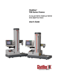
1
Cat. No. V236-E1-03 SYSMAC CS1W-SPU01/SPU02-V2 CJ1W-SPU01-V2 SYSMAC SPU Units OPERATION MANUAL CS1W-SPU01/SPU02-V2 CJ1W-SPU01-V2 SYSMAC SPU Units Operation Manual Revised August 2013 iv Notice: OMRON products are manufactured for use according to proper procedures by a qualified operator and only for the purposes described in this manual. The following conventions are used to indicate and classify precautions in this manual. Always heed the information provided with them. Failure to heed precautions can result in injury to people or damage to property. !DANGER Indicates an imminently hazardous situation which, if not avoided, will result in death or serious injury. Additionally, there may be severe property damage. !WARNING Indicates a potentially hazardous situation which, if not avoided, could result in death or serious injury. Additionally, there may be severe property damage. !Caution Indicates a potentially hazardous situation which, if not avoided, may result in minor or moderate injury, or property damage. OMRON Product References All OMRON products are capitalized in this manual. The word “Unit” is also capitalized when it refers to an OMRON product, regardless of whether or not it appears in the proper name of the product. The abbreviation “Ch,” which appears in some displays and on some OMRON products, often means “word” and is abbreviated “Wd” in documentation in this sense. The abbreviation “PLC” means Programmable Controller. “PC” is used, however, in some Programming Device displays to mean Programmable Controller. Visual Aids The following headings appear in the left column of the manual to help you locate different types of information. Note Indicates information of particular interest for efficient and convenient operation of the product. 1,2,3... 1. Indicates lists of one sort or another, such as procedures, checklists, etc. v Trademarks and Copyrights Adobe®, Adobe Acrobat®, and Adobe Reader® are registered trademarks of Adobe Systems Incorporated. Microsoft® and Windows® registered trademarks of the Microsoft Corporation. Ethernet® a registered trademark of the XEROX Corporation. FINS, SYSMAC, and FinsGateway are registered trademarks of the OMRON Corporation. Other product names and company names in this manual are trademarks or registered trademarks of their respective companies. The copyright of the SYSMAC SPU Unit belongs to OMRON Corporation. OMRON, 2007 All rights reserved. No part of this publication may be reproduced, stored in a retrieval system, or transmitted, in any form, or by any means, mechanical, electronic, photocopying, recording, or otherwise, without the prior written permission of OMRON. No patent liability is assumed with respect to the use of the information contained herein. Moreover, because OMRON is constantly striving to improve its high-quality products, the information contained in this manual is subject to change without notice. Every precaution has been taken in the preparation of this manual. Nevertheless, OMRON assumes no responsibility for errors or omissions. Neither is any liability assumed for damages resulting from the use of the information contained in this publication. vi Unit Versions of CS/CJ-series SYSMAC SPU Units Unit Versions A “Unit version” has been introduced to manage SYSMAC SPU Units in the CS/CJ Series according to differences in functionality accompanying Unit upgrades. Notation of Unit Versions on Products The Unit version is given to the right of the lot number on the nameplate of the applicable SYSMAC SPU Units, as shown below. Product nameplate SPU Unit CS1W-SPU01-V2 CPU UNIT Lot No. Unit version Example for Unit Ver. 2.1 Lot No. 050615 OMRON Corporation Checking the Unit Version from the SPU-Console Ver.2.1 MADE IN JAPAN A SYSMAC SPU Unit’s version can be checked from the SPU Console by clicking the Unit Information Tab and displaying the System Information Tab Page. The unit version appears next to the model number in the Product Information Area. The unit version can be checked from the CX-Programmer (Ver. 4.0 or higher) by selecting Unit Manufacturing Information. Functions Supported by SYSMAC SPU Units According to Unit Versions CS1W-SPU01/02-V2 and CJ1W-SPU01-V2 Unit version of SYSMAC SPU Unit Function Recipe function Expanded recipe function Copy option CHANNEL_BLOCK data type FTP communications Record counter and file copy flag 2.0 Supported --Supported Supported ----- 2.1 2.2 Supported Supported Supported Note The system program can be updated to update the unit version. Refer to Appendix E Updating the System Program in the SPU-Console Ver. 2.2 Operation Manual for information on updating the system program. vii SPU-Console Compatibility with Unit Versions of SYSMAC SPU Units CS1W-SPU01/02-V2 and CJ1W-SPU01-V2 Unit version of SYSMAC SPU Unit 2.0 2.1 SPU-Console SPU Basic Software SPU-Console version 1.X Cannot be connected. Cannot be connected. SPU-Console version 2.0 Can be connected. SPU-Console version 2.1 Can be connected. Can be connected. (Initial Setting Wizard cannot be used.) Can be connected. SPU-Console version 2.2 Can be connected. Can be connected. Note 2.2 Cannot be connected. Can be connected. (Initial Setting Wizard cannot be used.) Can be connected. (Initial Setting Wizard cannot be used.) Can be connected. 1. SPU-Console versions lower than version 2.0 cannot connect to SYSMAC SPU Units with a unit version of 2.0 or higher. 2. SPU-Console version 2.0 or 2.1 can connect to SYSMAC SPU Units with a unit version of 2.2. However, the Initial Setting Wizard cannot be used for unit version 2.2 in this case. Use the Initial Setting Wizard that is provided with CPU-Console version 2.2 or perform the initial settings with the CPU Bus Unit settings of the CX-Programmer. 3. SPU-Console version 2.2 can connect to SYSMAC SPU Units with a unit version of 2.0 or 2.1. In this case, the SPU-Console will operate in the version that corresponds to the unit version of the SYSMAC SPU Unit. viii TABLE OF CONTENTS PRECAUTIONS . . . . . . . . . . . . . . . . . . . . . . . . . . . . . . . . . . . xv 1 Intended Audience . . . . . . . . . . . . . . . . . . . . . . . . . . . . . . . . . . . . . . . . . . . . . . . . . . . . . . . . . xvi 2 General Precautions . . . . . . . . . . . . . . . . . . . . . . . . . . . . . . . . . . . . . . . . . . . . . . . . . . . . . . . . xvi 3 Safety Precautions . . . . . . . . . . . . . . . . . . . . . . . . . . . . . . . . . . . . . . . . . . . . . . . . . . . . . . . . . xvii 4 Operating Environment Precautions . . . . . . . . . . . . . . . . . . . . . . . . . . . . . . . . . . . . . . . . . . . xvii 5 Application Precautions. . . . . . . . . . . . . . . . . . . . . . . . . . . . . . . . . . . . . . . . . . . . . . . . . . . . . xviii 6 Conformance to EC Directives . . . . . . . . . . . . . . . . . . . . . . . . . . . . . . . . . . . . . . . . . . . . . . . xxi SECTION 1 Overview and Specifications . . . . . . . . . . . . . . . . . . . . . . . . . 1 1-1 Overview of the SYSMAC SPU Unit . . . . . . . . . . . . . . . . . . . . . . . . . . . . . . . . . . . . . . . . . . 2 1-2 SYSMAC SPU Unit Features . . . . . . . . . . . . . . . . . . . . . . . . . . . . . . . . . . . . . . . . . . . . . . . . 4 1-3 Product Configuration . . . . . . . . . . . . . . . . . . . . . . . . . . . . . . . . . . . . . . . . . . . . . . . . . . . . . . 6 1-4 Specifications. . . . . . . . . . . . . . . . . . . . . . . . . . . . . . . . . . . . . . . . . . . . . . . . . . . . . . . . . . . . . 6 SECTION 2 Installation and Wiring . . . . . . . . . . . . . . . . . . . . . . . . . . . . . 15 2-1 Part Names and Functions . . . . . . . . . . . . . . . . . . . . . . . . . . . . . . . . . . . . . . . . . . . . . . . . . . . 16 2-2 Mounting to the Backplane . . . . . . . . . . . . . . . . . . . . . . . . . . . . . . . . . . . . . . . . . . . . . . . . . . 22 2-3 Connecting the LAN Cable . . . . . . . . . . . . . . . . . . . . . . . . . . . . . . . . . . . . . . . . . . . . . . . . . . 23 2-4 Connecting the Power Failure Signal . . . . . . . . . . . . . . . . . . . . . . . . . . . . . . . . . . . . . . . . . . 23 2-5 Handling a PC Card or Memory Card . . . . . . . . . . . . . . . . . . . . . . . . . . . . . . . . . . . . . . . . . . 25 2-6 Initial Settings for the SYSMAC SPU Unit. . . . . . . . . . . . . . . . . . . . . . . . . . . . . . . . . . . . . . 27 SECTION 3 Troubleshooting and Maintenance . . . . . . . . . . . . . . . . . . . . 29 3-1 Seven-segment Display . . . . . . . . . . . . . . . . . . . . . . . . . . . . . . . . . . . . . . . . . . . . . . . . . . . . . 30 3-2 Restrictions and Precautions . . . . . . . . . . . . . . . . . . . . . . . . . . . . . . . . . . . . . . . . . . . . . . . . . 31 3-3 Inspection and Unit Replacement Precautions . . . . . . . . . . . . . . . . . . . . . . . . . . . . . . . . . . . 34 3-4 Restarting the SYSMAC SPU Unit . . . . . . . . . . . . . . . . . . . . . . . . . . . . . . . . . . . . . . . . . . . 35 Index. . . . . . . . . . . . . . . . . . . . . . . . . . . . . . . . . . . . . . . . . . . . . 37 Revision History . . . . . . . . . . . . . . . . . . . . . . . . . . . . . . . . . . . 39 ix x About this Manual: This manual describes the installation and operation of the CS1W-SPU01, CS1W-SPU02, and CJ1WSPU01 SYSMAC SPU Units and includes the sections described below. Please read this manual and all related manuals listed in the following table, and be sure you understand the information provided before attempting to install or operate a SYSMAC SPU Unit. Be sure to read the precautions provided in the following section. Name Cat. No. CS1W-SPU01-V2/SPU02-V2 V236 CJ1W-SPU01-V2 SYSMAC SPU Units Operation Manual (this manual) WS02-SPTC1-V2 V237 SPU-Console Ver. 2.1 Operation Manual WS02-EDMC1-V2 V232 SYSMAC SPU Data Management Middleware User’s Manual Contents Describes the installation and operation of the SYSMAC SPU Units. Describes the installation and operation of the SYSMAC SPU-Console Ver. 2.2. Describes the installation and operation of the SYSMAC SPU Data Management Middleware (EDMS). Precautions provide general precautions for using the SYSMAC SPU Unit, Programmable Controller, and related devices. Section 1 provides an overview of the SYSMAC SPU Units and their functionality and provides Unit specifications. Section 2 describes how to install and wire the SYSMAC SPU Units. Section 3 provides maintenance and inspection information. !WARNING Failure to read and understand the information provided in this manual may result in personal injury or death, damage to the product, or product failure. Please read each section in its entirety and be sure you understand the information provided in the section and related sections before attempting any of the procedures or operations given. xi xii Terms and Conditions Agreement Read and understand this Manual Please read and understand this catalog before purchasing the products. Please consult your OMRON representative if you have any questions or comments. Warranty, Limitations of Liability Warranties ● Exclusive Warranty Omron’s exclusive warranty is that the Products will be free from defects in materials and workmanship for a period of twelve months from the date of sale by Omron (or such other period expressed in writing by Omron). Omron disclaims all other warranties, express or implied. ● Limitations OMRON MAKES NO WARRANTY OR REPRESENTATION, EXPRESS OR IMPLIED, ABOUT NON-INFRINGEMENT, MERCHANTABILITY OR FITNESS FOR A PARTICULAR PURPOSE OF THE PRODUCTS. BUYER ACKNOWLEDGES THAT IT ALONE HAS DETERMINED THAT THE PRODUCTS WILL SUITABLY MEET THE REQUIREMENTS OF THEIR INTENDED USE. Omron further disclaims all warranties and responsibility of any type for claims or expenses based on infringement by the Products or otherwise of any intellectual property right. ● Buyer Remedy Omron’s sole obligation hereunder shall be, at Omron’s election, to (i) replace (in the form originally shipped with Buyer responsible for labor charges for removal or replacement thereof) the non-complying Product, (ii) repair the non-complying Product, or (iii) repay or credit Buyer an amount equal to the purchase price of the non-complying Product; provided that in no event shall Omron be responsible for warranty, repair, indemnity or any other claims or expenses regarding the Products unless Omron’s analysis confirms that the Products were properly handled, stored, installed and maintained and not subject to contamination, abuse, misuse or inappropriate modification. Return of any Products by Buyer must be approved in writing by Omron before shipment. Omron Companies shall not be liable for the suitability or unsuitability or the results from the use of Products in combination with any electrical or electronic components, circuits, system assemblies or any other materials or substances or environments. Any advice, recommendations or information given orally or in writing, are not to be construed as an amendment or addition to the above warranty. See http://www.omron.com/global/ or contact your Omron representative for published information. Limitation on Liability; Etc OMRON COMPANIES SHALL NOT BE LIABLE FOR SPECIAL, INDIRECT, INCIDENTAL, OR CONSEQUENTIAL DAMAGES, LOSS OF PROFITS OR PRODUCTION OR COMMERCIAL LOSS IN ANY WAY CONNECTED WITH THE PRODUCTS, WHETHER SUCH CLAIM IS BASED IN CONTRACT, WARRANTY, NEGLIGENCE OR STRICT LIABILITY. xiii Further, in no event shall liability of Omron Companies exceed the individual price of the Product on which liability is asserted. Application Considerations Suitability of Use Omron Companies shall not be responsible for conformity with any standards, codes or regulations which apply to the combination of the Product in the Buyer’s application or use of the Product. At Buyer’s request, Omron will provide applicable third party certification documents identifying ratings and limitations of use which apply to the Product. This information by itself is not sufficient for a complete determination of the suitability of the Product in combination with the end product, machine, system, or other application or use. Buyer shall be solely responsible for determining appropriateness of the particular Product with respect to Buyer’s application, product or system. Buyer shall take application responsibility in all cases. NEVER USE THE PRODUCT FOR AN APPLICATION INVOLVING SERIOUS RISK TO LIFE OR PROPERTY WITHOUT ENSURING THAT THE SYSTEM AS A WHOLE HAS BEEN DESIGNED TO ADDRESS THE RISKS, AND THAT THE OMRON PRODUCT(S) IS PROPERLY RATED AND INSTALLED FOR THE INTENDED USE WITHIN THE OVERALL EQUIPMENT OR SYSTEM. Programmable Products Omron Companies shall not be responsible for the user’s programming of a programmable Product, or any consequence thereof. Disclaimers Performance Data Data presented in Omron Company websites, catalogs and other materials is provided as a guide for the user in determining suitability and does not constitute a warranty. It may represent the result of Omron’s test conditions, and the user must correlate it to actual application requirements. Actual performance is subject to the Omron’s Warranty and Limitations of Liability. Change in Specifications Product specifications and accessories may be changed at any time based on improvements and other reasons. It is our practice to change part numbers when published ratings or features are changed, or when significant construction changes are made. However, some specifications of the Product may be changed without any notice. When in doubt, special part numbers may be assigned to fix or establish key specifications for your application. Please consult with your Omron’s representative at any time to confirm actual specifications of purchased Product. Errors and Omissions Information presented by Omron Companies has been checked and is believed to be accurate; however, no responsibility is assumed for clerical, typographical or proofreading errors or omissions. xiv PRECAUTIONS This section provides general precautions for using the CS1W-SPU01-V2, CS1W-SPU02-V2, and CJ1W-SPU01-V2 SYSMAC SPU Units. The information contained in this section is important for the safe and reliable application of SYSMAC SPU Units. You must read this section and understand the information contained before attempting to set up or operate a SYSMAC SPU Unit. 1 2 3 4 5 6 Intended Audience . . . . . . . . . . . . . . . . . . . . . . . . . . . . . . . . . . . . . . . . . . . . . General Precautions . . . . . . . . . . . . . . . . . . . . . . . . . . . . . . . . . . . . . . . . . . . . Safety Precautions. . . . . . . . . . . . . . . . . . . . . . . . . . . . . . . . . . . . . . . . . . . . . . Operating Environment Precautions . . . . . . . . . . . . . . . . . . . . . . . . . . . . . . . . Application Precautions . . . . . . . . . . . . . . . . . . . . . . . . . . . . . . . . . . . . . . . . . Conformance to EC Directives . . . . . . . . . . . . . . . . . . . . . . . . . . . . . . . . . . . . 6-1 Applicable Directives . . . . . . . . . . . . . . . . . . . . . . . . . . . . . . . . . . . . 6-2 Concepts . . . . . . . . . . . . . . . . . . . . . . . . . . . . . . . . . . . . . . . . . . . . . . xvi xvi xvii xvii xviii xxi xxi xxi xv 1 Intended Audience 1 Intended Audience This manual is intended for the following personnel, who must also have knowledge of electrical systems (an electrical engineer or the equivalent). • Personnel in charge of installing FA systems. • Personnel in charge of designing FA systems. • Personnel in charge of managing FA systems and facilities. 2 General Precautions The user must operate the product according to the performance specifications described in the operation manuals. Before using the product under conditions which are not described in the manual or applying the product to nuclear control systems, railroad systems, aviation systems, vehicles, combustion systems, medical equipment, amusement machines, safety equipment, and other systems, machines, and equipment that may have a serious influence on lives and property if used improperly, consult your OMRON representative. Make sure that the ratings and performance characteristics of the product are sufficient for the systems, machines, and equipment, and be sure to provide the systems, machines, and equipment with double safety mechanisms. This manual provides information for programming and operating the Unit. Be sure to read this manual before attempting to use the Unit and keep this manual close at hand for reference during operation. !WARNING It is extremely important that a PLC and all PLC Units be used for the specified purpose and under the specified conditions, especially in applications that can directly or indirectly affect human life. You must consult with your OMRON representative before applying a PLC System to the above-mentioned applications. xvi 3 Safety Precautions 3 Safety Precautions !WARNING Do not attempt to disassemble, repair, or modify any Units. Any attempt to do so may result in malfunction, fire, or electric shock. !WARNING Do not touch any of the terminals or terminal blocks while the power is being supplied. Doing so may result in electric shock. !WARNING Fail-safe measures must be taken by the customer to ensure safety in the event of incorrect, missing, or abnormal signals caused by broken signal lines, momentary power interruptions, or other causes. Abnormal operation may result in serious accidents. !WARNING Interlock circuits, limit circuits, and similar safety measures must be provided in external circuits. (i.e., not in the CPU Unit.) Abnormal operation may result in serious accidents. !Caution Execute online editing only after confirming that no adverse effects will be caused by extending the cycle time. Otherwise, the input signals may not be readable. !Caution Confirm safety at the destination node before transferring a program to another node or changing contents of the I/O memory area. Doing either of these without confirming safety may result in injury. !Caution Tighten the screws on the terminal block of the AC Power Supply Unit to the torque specified in the operation manual. The loose screws may result in burning or malfunction. 4 Operating Environment Precautions !Caution Do not operate the Unit in the following locations: • Locations subject to direct sunlight. • Locations subject to temperatures or humidity outside the range specified in the specifications. • Locations subject to condensation as the result of severe changes in temperature. • Locations subject to corrosive or flammable gases. • Locations subject to dust (especially iron dust) or salts. • Locations subject to exposure to water, oil, or chemicals. • Locations subject to shock or vibration. xvii 5 Application Precautions !Caution Install the SYSMAC SPU Unit correctly as described in the CS Series Programmable Controllers Operation Manual or CJ Series Programmable Controllers Operation Manual. !Caution Take appropriate and sufficient countermeasures when installing systems in the following locations: • Locations subject to static electricity or other forms of noise. • Locations subject to strong electromagnetic fields. • Locations subject to possible exposure to radioactivity. • Locations close to power supplies. 5 Application Precautions Observe the following precautions when using the SYSMAC SPU Unit. !WARNING Always heed these precautions. Failure to abide by the following precautions could lead to serious or possibly fatal injury. • Always connect to a ground of 100 Ω or less when installing the Units. Not connecting to a ground of 100 Ω or less may result in electric shock. • Always turn OFF the power supply to the CPU Unit before attempting any of the following. Not turning OFF the power supply may result in malfunction or electric shock. • Mounting or dismounting SYSMAC SPU Units, CPU Units, or Memory Cassettes. • Assembling the Units. • Setting DIP switches or rotary switches. • Connecting cables or wiring the system. • Connecting or disconnecting connectors. !Caution Failure to abide by the following precautions could lead to faulty operation of the SYSMAC SPU Unit or the system, or could damage the SYSMAC SPU Unit. Always heed these precautions. • Always use the power supply voltages specified in the operation manuals. An incorrect voltage may result in malfunction or burning. • Take appropriate measures to ensure that the specified power with the rated voltage and frequency is supplied. Be particularly careful in places where the power supply is unstable. An incorrect power supply may result in malfunction. • Install external breakers and take other safety measures against short-circuiting in external wiring. Insufficient safety measures against short-circuiting may result in burning. • Install the Unit away from equipment that generates strong, high-frequency noise. • Do not apply voltages to the Input Units in excess of the rated input voltage. Excess voltages may result in burning. xviii 5 Application Precautions • Do not apply voltages or connect loads to the Output Units in excess of the maximum switching capacity. Excess voltage or loads may result in burning. • Disconnect the GR terminal from the LG terminal on the Power Supply Unit when performing insulation resistance tests or withstand voltage tests. Not disconnecting the GR terminal may result in burning. • Do not attempt to disassemble, repair, or modify any Units. Any attempt to do so may result in malfunction, fire, or electric shock. • Do not drop the SYSMAC SPU Unit or subject it to abnormal shock or vibration. • Make sure that all SYSMAC SPU Unit and CPU Unit mounting screws, terminal block screws, and cable connector screws are tightened to the torque specified in the relevant manuals. Incorrect tightening torque may result in malfunction. • Leave the label attached to the Unit when wiring. Removing the label may result in malfunction if foreign matter enters the Unit. • Remove the label after the completion of wiring to ensure proper heat dissipation. Leaving the label attached may result in malfunction. • Use crimp terminals for wiring. Do not connect bare stranded wires directly to terminals. Connection of bare stranded wires may result in burning. • Double-check all wiring and switch settings before turning ON the power supply. Incorrect wiring may result in burning. • Wire all connections correctly. • Mount Units only after checking terminal blocks and connectors completely. • Make sure that the terminal blocks, Memory Units, expansion cables, and other items with locking devices are locked in place. • Check the user program for proper execution before actually running it on the Unit. Not checking the program may result in unexpected operation. • After replacing a SYSMAC SPU Unit or CPU Unit, resume operation only after transferring to the new SYSMAC SPU Unit or CPU Unit the contents of the DM Area, HR Area, and other data required for resuming operation. Not doing so may result in an unexpected operation. • Do not place objects on top of the cables or other wiring lines. Doing so may break the cables. • Always use the power supply voltages specified in the operation manuals. An incorrect voltage may result in malfunction or burning. • Do not pull on the cables or bend the cables beyond their natural limit. Doing either of these may break the cables. • Confirm that no adverse effect will occur in the system before attempting any of the following. Not doing so may result in an unexpected operation. • Changing the operating mode of the CPU Unit (including the Startup Mode setting). • Force-setting/force-resetting any bit in memory. • Changing the present value of any word or any set value in memory. • Touch the Unit only after first touching a grounded metal object to discharge any static electricity from your body. • Do not remove the Memory Card while the CARD indicator is lit. Doing so may damage the files on the Memory Card. xix Application Precautions 5 • Do not turn OFF the power supply while Memory Card data is being accessed. Doing so may damage the files on the Memory Card. • Maintain the operating environment for the Memory Cards (such as the ambient operating temperature and other conditions). Request operating environment conditions from the manufacture of the card. OMRON is not responsible for the operation of any memory cards produced by other manufacturers. • We recommend making a backup of the PC Card or Memory Card to prevent loosing the data inadvertently, e.g., by mistakenly deleting it. • Only Memory Cards can be used in the PC Card slot in the CS-series SYSMAC SPU Unit. Modem cards and Ethernet cards, which are not Memory Cards, cannot be used. Do not insert anything but Memory Cards into the Memory Card slot. • Make sure that the Memory Card is in the guides when inserting it. Faulty operation may result if the Memory Card is not in the guides. • After inserting the Memory Card, always lock it in place with the Memory Card fittings or cover. The Memory Card may become disconnected if it is not locked in place, causing faulty operation. • Always confirm that the Memory Card is facing the correct direction before inserting it. If a Memory Card is forced into the slot in the wrong direction, the Memory Card or guides may be damaged. • Always confirm the command number displayed on the 7-segment display before pressing the ENTER button. Faulty operation may result if the command number is incorrect. • Never restart or turn OFF the power to the SYSMAC SPU Unit while changing settings such as the sampling settings. “P1,” “P2,” and through “PE” will be displayed on the 7-segment display while sampling settings are being changed. The SYSMAC SPU Unit is restarted or turned OFF before completing the change operation, the system file being changed may be damaged. • Do not turn OFF the power supply to the Unit while transferring the Unit parameters or other data. Doing so may result in incorrect data being transferred to the Unit or the Unit may malfunction. • With the CJ1W-SPU01-V2, do not connect anything other than a UPS to the COMM port. Doing so may inadvertently shut down the SYSMAC SPU Unit. • Before using FTP communications, use the CONFIRM FTP CONNECTION command (command 61) to make sure that FTP communications are enabled. Data will not be transferred if FTP communications are not enabled. • Do not disconnect the Ethernet cable during FTP communications. Also, do not turn OFF the power supply to any hub during FTP communications. The file being transferred with FTP will not be correct, possibly causing malfunctions. • When transferring a recipe file with FTP, be sure there is sufficient space available in the Memory Card. If there is not sufficient space, malfunctions may occur. • If the results of executing the CONFIRM FTP CONNECTION command (command 61) shows that FTP communications are not enabled, check the FTP server settings. They may be restricting FTP communications. xx 6 Conformance to EC Directives 6 6-1 Conformance to EC Directives Applicable Directives • EMC Directives • Low Voltage Directive 6-2 Concepts EMC Directives OMRON devices that comply with EC Directives also conform to the related EMC standards so that they can be more easily built into other devices or the overall machine. The actual products have been checked for conformity to EMC standards (see the following note). Whether the products conform to the standards in the system used by the customer, however, must be checked by the customer. EMC-related performance of the OMRON devices that comply with EC Directives will vary depending on the configuration, wiring, and other conditions of the equipment or control panel on which the OMRON devices are installed. The customer must, therefore, perform the final check to confirm that devices and the overall machine conform to EMC standards. Note Applicable EMS (Electromagnetic Susceptibility) and EMI (Electromagnetic Interference) Standards in the EMC (Electromagnetic Compatibility) standards are as follows: Unit CS1W-SPU01-V2 CJ1W-SPU02-V2 CJ1W-SPU01-V2 EMS EN 61000-6-2 EMI EN 61000-6-4 (Radiated emission: 10-m regulations) Low Voltage Directive Always ensure that devices operating at voltages of 50 to 1,000 V AC and 75 to 1,500 V DC meet the required safety standards for the PLC (EN 61131-2). xxi Conformance to EC Directives xxii 6 SECTION 1 Overview and Specifications This section provides an overview of the SYSMAC SPU Units and their functionality and provides Unit specifications. 1-1 Overview of the SYSMAC SPU Unit . . . . . . . . . . . . . . . . . . . . . . . . . . . . . . . 2 1-2 SYSMAC SPU Unit Features . . . . . . . . . . . . . . . . . . . . . . . . . . . . . . . . . . . . . 4 1-3 Product Configuration . . . . . . . . . . . . . . . . . . . . . . . . . . . . . . . . . . . . . . . . . . . 6 1-4 Specifications. . . . . . . . . . . . . . . . . . . . . . . . . . . . . . . . . . . . . . . . . . . . . . . . . . 6 1-4-1 SYSMAC SPU Unit Specifications. . . . . . . . . . . . . . . . . . . . . . . . . . 6 1-4-2 SPU-Console (Setting/Monitoring Software) Specifications . . . . . . 10 1-4-3 SYSMAC SPU Unit Sampling Specifications . . . . . . . . . . . . . . . . . 11 1 Overview of the SYSMAC SPU Unit 1-1 Section 1-1 Overview of the SYSMAC SPU Unit A SYSMAC SPU Unit is a CS/CJ-series CPU Bus Unit that periodically and automatically collects the specified I/O memory data from the CPU Unit and stores it in a Memory Card in CSV-format files. The SYSMAC SPU Unit has two modes that can be selected to suit the application: Data Storage Mode and Sampling Mode. The SYSMAC SPU Unit’s functions are different in these two modes. • Data Storage Mode (Unit Ver. 1.2 or Later) In this mode, the SYSMAC SPU Unit records the specified I/O memory data from the CPU Unit when a particular event occurs. This mode can record data when a particular bit goes ON or at a particular time. In addition, it is also possible to record data at a fixed time after the event occurs, although the time interval is not as precise as it is in Sampling Mode. A recipe function is also supported to enable writing numeral and textual data to the memory areas of the CPU Unit at the same time. This is useful for retooling and reproducing equipment status. Data Storage Mode is the default operating mode for a SYSMAC SPU Unit with unit version 2.0 or higher. • Sampling Mode In this mode, the SYSMAC SPU Unit samples the specified I/O memory data from the CPU Unit at regular time intervals. The time intervals are nearly constant, so the data can be recorded at particular times and more reliable information can be reproduced from the collected data. Either of these modes can be selected after the SYSMAC SPU Unit is installed. A personal computer can be connected to the LAN port on the SYSMAC SPU Unit to use the SPU-Console SPU Basic Software to set the variable settings, collection pattern settings, set and control the CPU Unit, and display trend graphs. A Windows computer on a Windows network can also access the SYSMAC SPU Unit via Ethernet to share the files saved in the Memory Card in the SYSMAC SPU Unit. The SYSMAC SPU Unit thus enables collecting and saving large quantities of digital data without affecting the control operation of the PLC merely by adding a SYSMAC SPU Unit, providing an easy means to see trends in process data, analyze relationships between data and quality, and achieve other data/ system management applications. 2 Section 1-1 Overview of the SYSMAC SPU Unit CS-series CPU Unit SPU Unit Setting/Monitoring Software SPU-Console My network Sharing files via Windows network Sampling Memory Card I/O memory Ethernet Select switch CPU Unit SPU Unit Starting/stopping sampling, etc. Enter button Example I/O memory D00000 ··· Memory Card Event memory CSV files D00099 When an I/O memory address becomes a specific value Sampling at the specified interval (realtime or normal) Note (1) Data Storage Mode Operation: Data can be collected when a particular event occurs, such as a memory event (e.g., when a data area word equals a set value) or scheduled event (e.g., at a specified date and time). When the Basic Collection Pattern is used, sampling can also be executed using the following procedures. (a) Sampling can be started manually from the SYSMAC SPU Unit or SPU-Console. (b) Sampling can be started automatically when the SYSMAC SPU Unit is started. (c) Sampling can be executed from the ladder program. (2) Sampling Mode Operation: Sampling can be started and stopped using the following methods. (a) Sampling can be controlled manually from the SYSMAC SPU Unit or SPU-Console. (b) Sampling can be started automatically when the SYSMAC SPU Unit is started. (c) Sampling can be executed from the ladder program. 3 Section 1-2 SYSMAC SPU Unit Features 1-2 SYSMAC SPU Unit Features Automatic Data Collection from CPU Unit without Any Special Programming The specified data from the I/O memory in the CPU Unit can be automatically sampled and saved without altering the ladder program in the CPU Unit. No External Data Collection Device Required A SYSMAC SPU Unit can be easily added whenever required to enable data collection and sampling. An external data collection device is not required. Easily Set Data Collection and Sampling Parameters with SPU Basic Software High-speed Sampling at Precise Sampling Periods (Sampling Mode) • Data collection and sampling parameters are easily set from the SPUConsole Basic Software. • The SPU-Console dynamically creates windows based on setting information in the SYSMAC SPU Unit. There is no need to select the model. Data Storage Mode: Basic Pattern Data can be collected at high-speed and at very precise intervals from the CPU Unit’s I/O memory areas (CIO, WR, HR, DM, and EM Areas). Examples: 25 sampling items: 5 ms 250 sampling items: 10 ms These times may not be possible for some settings. Note Sampling is not possible at intervals that are faster than the CPU Unit’s cycle time. This mode allows the operation of the system (factors such as analog data changes or timing of logical sequences) to be tracked very accurately in nearly realtime time intervals. Sampling Mode: Realtime Sampling Data can be collected at high-speed and at very precise intervals from the CPU Unit’s I/O memory areas (CIO, WR, HR, DM, and EM Areas). Examples: 25 sampling items: 5 ms 250 sampling items: 10 ms 500 sampling items: 20 ms These times may not be possible for some settings. Note Sampling is not possible at intervals that are faster than the CPU Unit’s cycle time. This mode allows the operation of the system (factors such as analog data changes or timing of logical sequences) to be tracked very accurately in nearly realtime time intervals. Sampling Triggered by an Event (Data Storage Mode, Unit Ver. 1.2 or Later) Data sampling can be started or stopped when a bit or word in the CPU Unit’s data area reaches a certain value (e.g., a specified bit goes ON or a word equals 100) or at scheduled times (e.g., at 17:00 or every hour). Event-triggered sampling can be used to easily record operations under certain conditions, to provide a snapshot of device status when an error occurs, to understand temporal changes in operation, to periodically collect device data, or to achieve many other jobs based on data in the CPU Unit. User-settable Data Recording Conditions 4 The SYSMAC SPU Unit can be set to record the collected data only when a particular condition is satisfied, such as while a specified bit is ON or a specified word equals a specified set value. This feature can be used in both Sampling Mode and Data Storage Mode. SYSMAC SPU Unit Features Scaling Function (Unit Ver. 1.2 or Later) High-volume Storage of CSV-format Data Section 1-2 The collected data can be scaled in the SYSMAC SPU Unit before being recorded. Both linear equation conversion and upper/lower limit conversion are supported. • Data is saved in CSV format so that it can be easily imported for analysis in Excel, databases, or other software. • With a CS-series SYSMAC SPU Unit, data is stored in a Memory Card mounted in the PC card slot of the SYSMAC SPU Unit using an HMCAP001 Memory Card Adapter. With a CJ-series SYSMAC SPU Unit, data is stored in a Memory Card mounted directly in the Memory Card slot of the SYSMAC SPU Unit. If the HMC-EF583 is used, large-capacity storage of 512 MB is possible. Sampling Data Concurrency During each cycle of the CPU Unit, data is transferred from the CPU Unit to the SYSMAC SPU Unit in a single batch and the data is written to files in the Memory Card to ensure data concurrency. Data is transferred to the SYSMAC SPU Unit during the I/O refresh period of the CPU Unit. Windows Network Supported Shared folders on a Windows network can be used to share files with a Windows computer. The CSV files containing the results of sampling on the Memory Card mounted in the PC card slot of the SYSMAC SPU Unit can be easily read from a Windows computer. In addition, the WS02-EDMC1 SYSMAC SPU Data Management Middleware (sold separately) can be used to automatically collect data files at the computer. Write Recipes without Programming (Data Storage Mode, Unit Version 2.0 or Later) When a write request is received from the CPU Unit, manufacturing parameters (numeric and textual data) can be written to I/O memory in the CPU Unit. This function is ideal for easily achieving tool changes and other applications. CPU Bus Unit Area Support The ladder program in the CPU Unit can be used to manipulate the SYSMAC SPU Unit by setting commands from the CPU Unit to the SYSMAC SPU Unit in the CPU Bus Unit Area in the CPU Unit. The status of the SYSMAC SPU Unit is also stored in the CPU Bus Unit Area. FTP Communications (Unit Version 2.1 or Later) You can send the files copied with the copy option to an FTP server. You can also receive recipe files from a host computer using FTP communications when a trigger occurs (e.g., when a bit turns ON). 5 Section 1-3 Product Configuration 1-3 Product Configuration The SYSMAC SPU Units and related products are listed in the following table. Model CS1W-SPU01-V2 CS1W-SPU02-V2 CJ1W-SPU01-V2 WS02-SPTC1-V2 HMC-EF183 HMC-EF283 HMC-EF583 HMC-AP001 Note 1-4 1-4-1 Name SYSMAC SPU Unit SYSMAC SPU Unit SYSMAC SPU Unit SPU-Console (SPU Basic Software) Memory Card Memory Card Memory Card Memory Card Adapter Specification One LAN port Two LAN ports One LAN port SPU Unit Setting Software Flash memory, 128-MB Flash memory, 256-MB Flash memory, 512-MB Adapts a Memory Card for use in a PC card slot. (See note.) CS1W-SPU01/02-V2 only. Specifications SYSMAC SPU Unit Specifications General Specifications CS1W-SPU01/SPU02-V2 SYSMAC SPU Units: Specifications conform to the general specifications of the SYSMAC CS-series CPU Units. CJ1W-SPU01-V2 SYSMAC SPU Units: Specifications conform to the general specifications of the SYSMAC CJ-series CPU Units. Functional and Performance Specifications Item Unit model number Applicable CPU Units Unit classification Unit number Mounting location No. of Units per PLC Interfaces PC card slot COMM port Ethernet (LAN) ports UPS power failure input 6 Specification CJ1W-SPU01-V2 CJ Series CS1W-SPU01/02-V2 CS Series CPU Bus Unit 0 to F CPU Backplane or CS-series Expansion Backplane (Cannot be mounted to C200H Expansion I/O Rack or SYSMAC BUS Remote I/O Slave Rack.) 16 Unit max. PC card Type II, 1 slot (Conforms to PC Card Standard Release 8.0.) Used by mounting Memory Card (see note) and HMC-AP001 Memory Card Adapter. For future expansion CPU Backplane or CJ-series Expansion Backplane Memory Card slot Used by mounting a Memory Card (see note). Connects to an uninterruptive power supply (UPS) for detection of power failure. CJ1W-SPU01: One port (10/100Base-TX, RJ45 Modular Connector) CS1W-SPU01-V2: One port (10/100BaseTX, RJ45 Modular Connector) CS1W-SPU02-V2: Two ports (10/100BaseTX, RJ45 Modular Connectors) 24 VDC (+10%/−15%) input None (UPS connected to COMM port.) Connect the power failure signal output line from the UPS. Section 1-4 Specifications Settings and operation Indications Item Unit number switch (UNIT) Select switch (SELECT) Enter button (ENTER) DIP switch (DIPSW) Card button LED indicators 7-segment display Functions Operating modes Current consumption Dimensions (mm) Weight Specification Rotary switch: Sets the unit number of the Unit as a CPU Bus Unit. Toggle switch: Sets the number of the command to execute. Pushbutton switch: Confirms and starts execution of the command number set using the select switch. DIP switch: System settings Pressed to release the Memory Card inserted Pressed to release the Memory Card in the Memory Card slot. The Memory Card inserted in the PC card slot. The Memory can then be removed. Card can then be removed. RUN, ERC, ERH, COMM, LAN1, LAN2, CARD, and PF-IN (See note.) Note PF-IN: CS1W-SPU01/SPU02-V2 only. • Displays error information and operating status of the SYSMAC SPU Unit. • Displays the command number set on the select switch. • Displays the IP address. • Display other information. • Sampling • Saving files • Network communications • Recipe function Data Storage Mode and Sampling Mode (Either mode can be selected with the Change Operating Mode command.) CJ1W-SPU01-V2: CS1W-SPU01-V2: 5 VDC, 560 mA max. (SYSMAC SPU Unit 5 VDC, 560 mA max. (SYSMAC SPU Unit only) only) Other: Memory Card (HMC-EF@@@): Other: Memory Card (HMC-EF@@@): 120 mA max. 120 mA max. (Supplied from Power Supply Unit.) (Supplied from Power Supply Unit.) CS1W-SPU02-V2: 5 VDC, 700 mA max. (SYSMAC SPU Unit only) Other: Memory Card (HMC-EF@@@): 120 mA max. (Supplied from Power Supply Unit.) CS1W-SPU01/SPU02-V2: CJ1W-SPU01-V2: 35 × 130 × 101 mm (W × H × D) 51 × 90 × 65 mm (W × H × D) CS1W-SPU01-V2: CJ1W-SPU01-V2: 280 g max. (including enclosed connector) 180 g max. CS1W-SPU02-V2: 290 g max. (including enclosed connector) Note Memory Card: HMC-EF@@@ Memory Card from OMRON or commercially available compact flash card. Normal operation may not be possible with commercially available compact flash cards depending on the manufacturer and model of the card. 7 Section 1-4 Specifications Detailed Specifications (Same for CS1W-SPU01-V2/02-V2 and CJ1W-SPU01-V2) Sampling Item Sampling Mode Sampling patterns Starting methods Interval Data Storage Mode Data Collection Patterns Starting methods Interval Copy option 8 Specification Realtime sampling: 1 pattern Normal sampling: Up to 3 patterns Any one of the following methods can be used: • Start automatically when SYSMAC SPU Unit is started. • Start with an SPU-Console operation. • Start with the SYSMAC SPU Unit’s front-panel command buttons. (Specify the command number.) • Start from the CPU Unit’s ladder program. User-specified intervals: Realtime sampling: 5 ms min. Normal sampling: 100 ms min. Note In both cases, the sampling cannot be performed faster than the CPU Unit’s cycle time. The actual sampling interval will always be longer than the CPU Unit’s cycle time even if the sampling interval is set shorter than the cycle time. Basic Collection Pattern: 1 pattern (required) Data Collection Patterns: Up to 64 patterns Basic Collection Pat- Any one of the following methods can be used: tern (required) • Start when a specified event occurs. (Use a memory event or scheduled event. For details, see the description of Data Collection Patterns 1 to 64 below.) • Start automatically when SYSMAC SPU Unit is started. • Start with an SPU-Console operation. • Start with the SYSMAC SPU Unit’s frontpanel command buttons. (Specify the command number.) • Start from the CPU Unit’s ladder program. Data Collection Pat- Either of the following methods can be used to terns 1 to 64 start when an event occurs: • Memory events: Start when a CPU Unit bit or word value matches a specified condition. Up to 500 memory events can be specified. • Scheduled events: Start at a specified time or time interval. Up to 16 scheduled events can be specified. User-specified intervals: Basic Collection Pattern: 5 ms to 35 min Data Collection Patterns: 100 ms to 35 min Note 1. The Data Collection Patterns use the data collected by the Basic Collection Pattern, so the data will be collected at the Basic Collection Pattern’s interval even if the Data Collection Pattern’s interval is set shorter than the Basic Collection Pattern’s interval. 2. The actual Basic Collection Pattern interval will always be longer than the CPU Unit’s cycle time even if the sampling interval is set shorter than the cycle time. Basic Collection Pattern: Cannot be set. Data Collection Patterns: Up to 10 patterns. Maximum number of saved files: 120 Section 1-4 Specifications Item Sampling, Shared Samcontinued pling Mode and Data Storage Mode settings Applicable CPU Unit I/O memory areas Specifying I/O memory areas Specification CIO Area, WR Area, HR Area, AR Area, DM Area, and EM Area banks 0 to 18 Specify the desired CPU Unit I/O memory area (data area) with a variable. The data type can be specified with the variable. The variables can be managed in groups. Variable data types Saving files Network communications BOOL, INT, UINT, DINT, UDINT, REAL, LREAL, STRING, CHANNEL, UINT BCD, UDINT BCD, WORD, DWORD, CHANNEL BLOCK Settable variables Variable names: Single-byte or double-byte characters. Up to 63 bytes including the group name. Maximum number of variables: 7,776 words total for all variables The maximum number may be reduced depending on the areas and addresses of the variables. Record Condition Set whether or not to use a record condition. setting If a record condition is used, sampling data is stored within the SYSMAC SPU Unit only when the record condition is met. For example, sampling data can be recorded only while a specified bit is ON or a specified word contains a particular value (comparison). Data exchange with CPU Bus Unit Area the CPU Unit • CPU Unit to SYSMAC SPU Unit: Command execution (such as starting/stopping sampling, clearing a sampling file, or saving a sampling file). • SYSMAC SPU Unit to CPU Unit: SYSMAC SPU Unit status information Collected data file CSV files Indices (record number), time stamps format (hh:mm:ss:ms), ns, sampling indices (serial Record contents numbers starting at 0 when sampling is started), data for each symbol delimited with comma, records delimited with carriage returns Any one of the following methods can be used. Number of sampling result records • The number of records can be specified. stored in one file • A time period can be specified. (The number of records is calculated automatically from the time period and interval between samples.) • With a version 1.2 or later SYSMAC SPU Unit, the number of records can be left unspecified. (In this case, data is added to the file until data collection is stopped. Records are added to one file from the start of data collection until the end.) Scaling Instead of directly storing the values collected from the CPU Unit’s I/O memory, the collected values can be scaled with a linear equation or upper/lower limit range before storage (unit version 1.2 or later). File size 2 GB per file Record size User specified or automatic Number of records Specified by user or calculated automatically. Saving method Data can be saved to a single file or multiple files (up to 1,200 files). File names 96 single-byte alphanumeric characters max. Windows network Files in the Memory Card inserted in the PC card slot in the SYSMAC shared folders SPU Unit can be shared with a Windows personal computer. FTP server FTP server provided. FINS communica- • FINS server to execute FINS command tions • Routing to transfer FINS messages 9 Section 1-4 Specifications Recipe function Item Data Storage Mode (Unit Ver. 2.0 or later) Number of fields Recipe files Number of records Writing method Searching for recipe keys 1-4-2 SPU-Console (Setting/Monitoring Software) Specifications Item Model number System require- Computer hardware ments CD-ROM drive Display Mouse Network card OS Application platform Communications platform Functions Unit information Monitor Operation Unit setup Variable settings Collection Pattern settings Event settings (for Data Storage Mode) Trend graphs 10 Specification 10,000 File format: CSV The file size is restricted by the size of file that can be stored in the recipe folder. Records: Specified by the user. No limit, but restricted by the file size that can be stored in the recipe folder. Conversion method: Each field is written to the specified address in the specified data type. Continuous region method: Data written to continuous memory addresses. Searching within files: The text string that was passed as the key is searched for in the target search columns in the recipe files and the rows for any matches that are found are extracted as recipe data. Searching for file names: The text string that was passed as the key is searched for in the recipe file names (i.e., a search is made for key.csv), and the files with matching files names are used as recipe files just like previous versions. Key list search: A search is made for recipe keys with the method used for unit version 2.0. Memory Event Schedule Event Historical trends Realtime trends (Sampling Mode) Specification WS02-SPTC1-V2 (SPU-Console Ver. 2.2) Computer that meets the system requirements for Microsoft Windows Required for installation. Super VGA (800 × 600) or better high-resolution video adapter and monitor Must conform to the models supported by the applicable OS. A separate Ethernet network card is required for computers that do not have a LAN port. Microsoft Windows XP Home Edition/Professional Microsoft Windows Vista Microsoft Windows 7 (32-bit/64-bit edition) Microsoft Windows 8 (32-bit/64-bit edition) Microsoft.NET Framework Version 1.1 Microsoft.NET Framework Version 2.0 FinsGateway Version 2003 Unit information, Unit setup, variable settings, collection pattern settings, event settings, and trend graphs SYSMAC SPU Unit operating status and error information are displayed. Operations, such as starting sampling IP network settings FINS network settings Setting items to sample (by specifying I/O memory addresses using variables) Collection pattern settings (interval, specification of save filename, etc.) Set the condition as a change in the CPU Unit’s memory status, such as a specified bit going ON. Set a scheduled event, such as a specified time or time difference. CSV files are read and displayed. Current sampling data is read and displayed in trend graphics in real time. Section 1-4 Specifications Note (1) SPU-Console versions lower than version 2.0 cannot connect to SYSMAC SPU Units with a unit version of 2.0 or higher. (2) SPU-Console version 2.0 or 2.1 can connect to SYSMAC SPU Units with a unit version of 2.2. However, the Initial Setting Wizard cannot be used for unit version 2.2 in this case. Use the Initial Setting Wizard that is provided with CPU-Console version 2.2 or perform the initial settings with the CPU Bus Unit settings of the CX-Programmer. (3) SPU-Console version 2.2 can connect to SYSMAC SPU Units with a unit version of 2.0 or 2.1. In this case, the SPU-Console will operate in the version that corresponds to the unit version of the SYSMAC SPU Unit. 1-4-3 SYSMAC SPU Unit Sampling Specifications Sampling Capacity The sampling capacity of the SYSMAC SPU Unit varies with the following factors: • Operating Mode (Data Storage Mode or Sampling Mode) • Sampling period • Quantity of variables recorded as sampling data • Number of files used to save sampled data • Writing speed of media where sampling data is saved • Number of samplings that are set • CPU Unit cycle time There are no predetermined restrictions on these factors for SYSMAC SPU Unit sampling. It is assumed that the required sampling will be tested on the actual system to confirm applicability. We recommend that the above factors be studied and tested sufficiently before using the sampling function in an actual system to determine suitable settings. Examples: • When precise sampling periods are required, use Sampling Mode. • To shorten the sampling period: • Reduce the quantity of sampling data. • Reduce the number of sets of data being sampled. • Use a faster storage media. • To record a large volume of sampling data: • Increase the sampling period. Realtime Sampling Characteristic Data Storage Mode In Data Storage Mode, only the Basic Collection Pattern reads data from the CPU Unit’s I/O memory to the SYSMAC SPU Unit. The other Data Collection Patterns (patterns 1 to 64) use the data collected by the Basic Collection Pattern and record the data when the corresponding event condition setting is met. Data Collection Patterns 1 to 64 use the data collected by the Basic Collection Pattern, so the interval settings for the Data Collection Patterns must be longer than the interval setting for the Basic Collection Pattern. We recommend thoroughly testing the settings in trial operation before using the data collection functions in actual operation. 11 Section 1-4 Specifications Sampling Mode With realtime sampling, sampling is performed by the SYSMAC SPU Unit as much as possible according to the sampling settings. The following conditions, however, may prevent sampling from being performed at completely fixed intervals. Be sure to consider possible affects of this on the application in advance. • Offset between the timer accuracy and the time of the SYSMAC SPU Unit • Changes in the sampling period during compensation by the time compensation function with the CPU Unit • Delays caused by system traffic, particularly concentrated access to the storage media To handle these problems, the SYSMAC SPU Unit provides time stamps with sampling data. We recommend that tests be performed in advance so that the results of sampling are not radically different from those for fixed-interval sampling. Relationship to Cycle Time of CPU Unit • The SYSMAC SPU Unit collects I/O memory data during the I/O refresh period of the CPU Unit. The cycle time of the CPU Unit, however, will be longer when the SYSMAC SPU Unit is sampling I/O memory. The affect of the SYSMAC SPU Unit on the CPU Unit cycle time depends on the series of CPU Unit, as given below. • CS1 CPU Units: 1.0 ms + No. of words sampled × 1 µs • CS1H CPU Units: 0.2 ms + No. of words sampled × 0.8 µs • CJ1H CPU Units: 0.2 ms + No. of words sampled × 0.8 µs • CJ1M CPU Units: 0.2 ms + No. of words sampled × 0.8 µs • CJ2H CPU Unit: 0.2 ms + Number of sampled words × 0.8 µs • CJ2M CPU Unit: 0.2 ms + Number of sampled words × 1.1 µs • The sampling period of the SYSMAC SPU Unit cannot be shorter than the cycle time of the CPU Unit. This is because the SYSMAC SPU Unit uses the I/O refresh period of the CPU Unit’s cycle time to collect data. If a sampling period is set that is shorter than the cycle time of the CPU Unit, I/O memory will be collected and sampled at an period equivalent to the cycle time of the CPU Unit. • When the CPU Unit is in PROGRAM mode, the CPU Unit’s cycle time will be longer so it may not be possible to read the data within the set time interval. Note Sampling File Size To perform sampling at an interval that is as close as possible to the cycle time of the CPU Unit, set the sampling cycle to a value that is shorter than the cycle time of the CPU Unit. For details, refer to 8-2 Data Collection Timing in the SYSMAC SPU-Console Ver. 2.2 Operation Manual (Cat. No. 237). • The maximum size of one data collection file or sampling file is 2 GB. • If sufficient space cannot be secured in advance for the sampling settings, the disk may become full during sampling, causing an error. • Depending on the file sizes, time may be required to change data collection (sampling) settings to secure space in advance. Restrictions in Variable Assignments 12 • The maximum total size of all variables is 7,776 words. • The SYSMAC SPU Unit keeps all of the variable addresses in continuous memory blocks. There can be a maximum of 19 blocks (17 blocks for unit version 2.1). Section 1-4 Specifications If the maximum number of blocks is exceeded, the SYSMAC SPU Unit will attempt to place the variables with non-continuous addresses into the blocks. As a result, the total size of the blocks may exceed 7,776 words and error 44 (exceeded total size range for cyclic data) may occur when you attempt to change the settings. If this occurs, reduce the number of variables or adjust the memory allocations so that variable addresses are consecutive. Example If you register one variable every 100 words from DM00000 to DM09900, the total size for the 100 variables will be 100 words. However, the variables are not consecutive, so 100 blocks would be necessary, but that exceeds the maximum number of blocks. Therefore, the allocations are changed so that the 8,101 words from DM00000 to DM08100 are placed in one block, and the allocated words between DM08200 and DM09900 are each placed in a 1-word block, for a total of 19 blocks. As a result, the total size of all blocks is 8,119 words, which exceeds 7,776 words. DM00000 : DM00000 to DM08100 are placed in one block. This results in a block size of 8,101 words. DM08100 DM08100 DM08200 DM08200 DM08300 DM08300 : 18 blocks from DM08200 to DM09900 DM09800 DM09800 DM09900 DM09900 13 Specifications 14 Section 1-4 SECTION 2 Installation and Wiring This section describes how to install and wire the SYSMAC SPU Units. 2-1 Part Names and Functions . . . . . . . . . . . . . . . . . . . . . . . . . . . . . . . . . . . . . . . . 16 2-1-1 Part Names . . . . . . . . . . . . . . . . . . . . . . . . . . . . . . . . . . . . . . . . . . . . 16 2-1-2 Indicators. . . . . . . . . . . . . . . . . . . . . . . . . . . . . . . . . . . . . . . . . . . . . . 17 2-1-3 Seven-segment Display . . . . . . . . . . . . . . . . . . . . . . . . . . . . . . . . . . . 18 2-1-4 Setting the Unit Number . . . . . . . . . . . . . . . . . . . . . . . . . . . . . . . . . . 18 2-1-5 Setting the DIP Switch . . . . . . . . . . . . . . . . . . . . . . . . . . . . . . . . . . . 19 2-1-6 Select Switch and Enter Button. . . . . . . . . . . . . . . . . . . . . . . . . . . . . 19 2-1-7 Starting CPU Unit Operation Immediately upon Power Application 20 2-1-8 Dimensions . . . . . . . . . . . . . . . . . . . . . . . . . . . . . . . . . . . . . . . . . . . . 22 2-2 Mounting to the Backplane . . . . . . . . . . . . . . . . . . . . . . . . . . . . . . . . . . . . . . . 22 2-3 Connecting the LAN Cable . . . . . . . . . . . . . . . . . . . . . . . . . . . . . . . . . . . . . . . 23 2-4 Connecting the Power Failure Signal . . . . . . . . . . . . . . . . . . . . . . . . . . . . . . . 23 2-5 Handling a PC Card or Memory Card . . . . . . . . . . . . . . . . . . . . . . . . . . . . . . . 25 2-5-1 CS1W-SPU01/SPU02-V2 . . . . . . . . . . . . . . . . . . . . . . . . . . . . . . . . . 25 2-5-2 CJ1W-SPU01-V2 . . . . . . . . . . . . . . . . . . . . . . . . . . . . . . . . . . . . . . . 26 Initial Settings for the SYSMAC SPU Unit. . . . . . . . . . . . . . . . . . . . . . . . . . . 27 2-6 15 Section 2-1 Part Names and Functions 2-1 Part Names and Functions The names and function of SYSMAC SPU Unit parts are described in this section. The meaning of indicators and the display is also described. 2-1-1 Part Names The parts of the SYSMAC SPU Unit are listed below. CS1W-SPU01/ SPU02-V2 Here, the CS1W-SPU02-V2, which has two LAN ports, is taken as an example. The CS1W-SPU01-V2 has only one LAN port. SPU02 Indicators Unit number switch Card button RUN ERC ERH COMM CS 7-segment display Card eject button Card holder Card indicator COMM port PC card slot PF-IN terminals Recognition retry switch PF-IN indicator LAN indicator DIP switch Select switch LAN ports (CS1W-SPU01-V2: One port, CS1W-SPU02-V2: Two ports) Enter button Name Unit number switch (UNIT NO.) DIP switch (DIP SW) Card button (CARD SW) Card eject button Card holder Select switch Enter button Indicators Seven-segment display LAN indicator Card indicator PF-IN indicator PC card slot Communications ports LAN1/LAN2 COMM port 16 Function Sets the unit number of the SYSMAC SPU Unit as a one-digit hexadecimal value. Do not set the same unit number for more than one CPU Bus Unit under the same CPU Unit. Used for system settings. Press this button to allow the Memory Card inserted in the PC card slot to be removed. Press to remove the PC card. Holds the PC card. Sets the command to be executed. The command number will be displayed on the sevensegment display. Executes the command set using the select switch. The following indicators show the operating status of the Unit: RUN, ERC, ERH, and COMM. Displays error information and the operating status of the SYSMAC SPU Unit. Displays the command number when the select switch is operated. Displays the IP address and other results of command execution. Indicates the operating status of the LAN port. Indicates the operating status of the PC card. Lights when the power failure input is received from a UPS or other device. A slot used to insert a card conforming to PC Card Type II. LAN communications ports. Connect to 10Base-T/100Base-TX cables. For future expansion. Section 2-1 Part Names and Functions Name PF-IN terminals Recognition retry switch Function Connected to the power failure input from a UPS or other device. Refer to 2-1-7 Starting CPU Unit Operation Immediately upon Power Application. CJ1W-SPU01-V2 SPU01 RUN ERC ERH COMM 7-segment display Card eject button CARD LAN Indicators UNIT UNIT NO. NO. Unit number switch CARD CARD SW SW Card button Memory Card slot DIP switch DIP SW COMM port (Power interrupt signal input) LAN LAN port Select switch ENTER COMM Enter button DIN Track mounting pins Name Unit number switch (UNIT NO.) DIP switch (DIP SW) Card button (CARD SW) Card eject button Select switch Enter button Indicators Seven-segment display Memory Card slot LAN port COMM port 2-1-2 Back of Unit Function Sets the unit number of the SYSMAC SPU Unit as a one-digit hexadecimal value. Do not set the same unit number for more than one CPU Bus Unit under the same CPU Unit. Used for system settings. Press this button to allow the Memory Card inserted in the Memory Card slot to be removed. Press to remove the Memory Card. Sets the command to be executed. The command number will be displayed on the sevensegment display. Executes the command set using the select switch. The following indicators show the operating status of the Unit: RUN, ERC, ERH, COMM, CARD, and LAN. Displays error information and the operating status of the SYSMAC SPU Unit. Displays the command number when the select switch is operated. Displays the IP address and other results of command execution. The slot used to insert a Memory Card. LAN communications port. Connects to 10Base-T/100Base-TX cables. Connects to the power failure signal from an uninterruptive power supply (UPS). Indicators Name RUN indicator ERC indicator ERH indicator COMM indicator Color Green Red Red Orange LAN indicator Green Function Lit when the SYSMAC SPU Unit is operating normally. Lit when there is a controller error. Lit when there is a host error. Lit when communications are active on the COMM port (for future expansion). Lit when a LAN cable is connected. Flashing when data is being sent or received. 17 Section 2-1 Part Names and Functions Name Card indicator PF-IN indicator 2-1-3 Color Green Function CS1W-SPU01/SPU02-V2: Lit when the PC card is being used. Not lit when the PC card is not being used. CJ1W-SPU01-V2: Lit when the Memory Card is being used. Not lit when the Memory Card is not being used. Orange CS1W-SPU01/SPU02-V2: Lit when the PC card is being accessed. CJ1W-SPU01-V2: Lit when the Memory Card is being accessed. Red Lit when the power failure input is being received from a UPS or other device. (CS1W-SPU01/SPU02-V2 only.) Seven-segment Display The seven-segment display shows error information and operating conditions of the SYSMAC SPU Unit. It also displays command numbers when the select switch is manipulated, as well as command execution results. The seven-segment display shows alphanumeric characters and symbols. Alphabet characters are displayed as shown below. 2-1-4 Setting the Unit Number Set the unit number switch to a unique unit number for each CPU Bus Unit mounted under the same CPU Unit. Use a small, flat-blade screwdriver and be careful not to damage the slot. The default setting is 0. CS1W-SPU01/02-V2 6543 EF01 2345 6789 0 to F ABCD Setting range Setting range 0 to F EDCB UNIT NO. 210F CJ1W-SPU01-V2 A987 Note 18 Turn the power supply OFF before setting the unit number. Always create the I/O tables in the CPU Unit after setting the unit number for the first time or after changing the unit number. Section 2-1 Part Names and Functions 2-1-5 Setting the DIP Switch CS1W-SPU01/02-V2 CJ1W-SPU01-V2 1 6 2 5 3 2 6 1 5 Setting ----OFF ON SW4 OFF ON SW5 SW6 --OFF ON 2-1-6 ON Pin SW1 SW2 SW3 DIPSW 3 4 DIPSW 4 ON Meaning Not used. Keep set to OFF. Not used. Keep set to OFF. Setup file can be read. Setup file cannot be read and changes will not be possible from the Setting Software. This setting is used to prevent unintentional changes to settings. IP address is set according to the SYSMAC SPU Unit setup. The IP addresses are set to the following default values. LAN1 port = 192.168.0.100 LNA2 port = 192.168.2.100 Not used. Keep set to OFF. Starts the SYSMAC SPU Unit in normal operating mode. Starts the SYSMAC SPU Unit in maintenance mode. This setting is used to set up the SYSMAC SPU Unit. Default setting OFF OFF OFF OFF OFF OFF Select Switch and Enter Button The select switch and enter button on the SYSMAC SPU Unit can be manipulated to execute commands, such as one to start sampling. CS1W-SPU01/02-V2 CJ1W-SPU01-V2 Select switch LAN2 Select switch COMM Enter button Setting Commands on the Select Switch Enter button The command number will be incremented when the switch is press up and decremented when the switch is pressed down. The currently set command number will be displayed on the seven-segment display. Executing Commands with the Enter Button The enter button is used to executed the command set using the select switch. When the enter button is pressed once, the command number displayed on the seven-segment display will start flashing. When the enter button is pressed again, “A” will be displayed on the seven-segment display and the command will be executed. To cancel executing the command after pressing the enter button the first time, do not press the enter button again and wait for 10 s. 19 Part Names and Functions Section 2-1 The main commands are listed below. Refer to Section 6 Executing Commands in the SPU-Console Ver. 2.2 Operation Manual (Cat. No. V237). Command Command Function number 01 Start basic collection Starts collecting data for the basic collection pattern. 02 Stop basic collection Stops collecting data for the basic collection pattern. 03 Save the sampled Saves the sampled data file and settings file in a data ZIP file. 04 Clear the sampled Deletes contents of the data file. data 05 Display the IP Displays the IP address of LAN1 on the sevenaddress (LAN1) segment display. 06 Display the IP Displays the IP address of LAN2 on the sevenaddress (LAN2) segment display. 07 Display the unit Displays the name of the Unit on the seven-segname ment display. 08 Display the FINS Displays the FINS address of the Ethernet Comaddress munications Unit on the seven-segment display. 09 Display of Memory Displays the percentage of the Memory Card Card used space (%) capacity that has been used. 10 Error display Displays any errors that exist. 11 Forced clear of error Clears the record of any errors that exist. 2-1-7 Starting CPU Unit Operation Immediately upon Power Application If a SYSMAC SPU Unit is mounted to a PLC, a minimum of one second is required for SYSMAC SPU Unit initialization, and the CPU Unit will remain on standby until initialization has been completed. This means that the CPU Unit will not start operation when the power supply is turned ON even if the startup mode of the CPU Unit is set to RUN or MONITOR mode. When using a CS1-H CPU Unit, the recognition retry switch on the SYSMAC SPU Unit can be turned ON to omit waiting for the completion of initialization and start operation of the CPU Unit as soon as the power supply is turned ON. If this is done, the SYSMAC SPU Unit will initially not participate in PLC operation. Note 20 With the CJ1W-SPU01-V2, the recognition retry function is always ON, and is not a switch. To start CPU Unit operation immediately, you must use a CS1H or CJ1/CJ2-series CPU Unit and you must set the Startup Condition setting in the PLC Setup to Don’t Wait. Use the following procedure. Section 2-1 Part Names and Functions 1,2,3... 1. Turn ON the recognition retry switch on the back of the SYSMAC SPU Unit. Recognition retry button (Default: OFF) ON Back of Unit If the CPU Unit is in RUN or MONITOR mode after the power supply is turned ON, operation will depend on the setting of the recognition retry button as follows: OFF: CPU Unit will remain on standby until initialization of the SYSMAC SPU Unit has been completed. ON: The CPU Unit will not go on standby and execution of the ladder program will be started. This function can be used only for a CS1-H CPU Unit. This operation is not required with the CJ1W-SPU01-V2, for which recognition retry processing is always ON. 2. For both the CS1W-SPU01/SPU02-V2 and the CJ1W-SPU01-V2, set the following setting in the PLC Setup from the CX-Programmer. Set PLC Setup - Execution Settings - Startup Condition to Don’t Wait. For details on the startup condition, refer to 7-1-2 PLC Setup Settings in the CS Series PLC Operation Manual (Cat. No. W339) and in the CJ Series PLC Operation Manual (Cat. No. W393). Note (1) Keep the recognition retry switch turned OFF when the SYSMAC SPU Unit is mounted under any CPU Unit other than a CS1-H CPU Unit. (2) If this switch is turned ON for other CPU Units, a unit number duplication error will occur. Note If you set the Startup Condition in the PLC Setup to Don’t wait, the CPU Unit will start operation without waiting for the SPU Unit to start. The SPU Unit will continue startup processing, but SPU Unit functions, such as data collection, will not operate. When the SPU Unit completes startup processing, it will change to initial or idle status. If you control the SPU Unit from the program, check the status of the SPU Unit first. You can check the status of the CPU Unit in the System Status in word n+8 of the words allocated to the Unit in the CPU Bus Area. 21 Section 2-2 Mounting to the Backplane 2-1-8 Dimensions CS1W-SPU01-V2 and CS1W-SPU02-V2 130 20 35 101 Unit: mm CJ1W-SPU01-V2 94.8 51 2-2 9 65 Unit: mm Mounting to the Backplane CS1W-SPU01/SPU02V2 The SYSMAC SPU Unit is used mounted to the CPU Backplane. Refer to the CS Series PLC Operation Manual (Cat. No. W339) for instructions on mounting to the Backplane. The SYSMAC SPU Unit must be counted as a CS-series CPU Bus Unit. A maximum of 16 CS-series CPU Bus Units can be mounted to one PLC. After mounting the SYSMAC SPU Unit to the Backplane and setting the unit number, turn ON the power supply to the PLC and create the I/O tables. Use a Programming Device, such as a Programming Console or the CX-Programmer, to create the I/O tables. Note 22 The maximum current consumption for CS1W-SPU01-V2 and CS1W-SPU02V2 SYSMAC SPU Units is 560 mA and 700 mA respectively. Make sure that Section 2-3 Connecting the LAN Cable the total current consumption of all the Units mounted to the same CPU Backplane or Expansion Backplane does not exceed the maximum output capacity of the Power Supply Unit. CJ1W-SPU01-V2 Connect the SYSMAC SPU Unit horizontally with the other Units. For details on connecting Units together, refer to the CJ Series PLC Operation Manual (Cat. No. W393). When mounting other CJ-series CPU Bus Units at the same time, the total number of CJ-series CPU Bus Units must not exceed 16. After the Units have been connected together and the unit numbers set, turn ON the power supply to the CPU Unit. Note 2-3 The maximum current consumption for an CJ1W-SPU01-V2 SYSMAC SPU Unit is 560 mA. Make sure that the total current consumption of all the Units mounted to the same CPU Backplane or Expansion Backplane does not exceed the maximum output capacity of the Power Supply Unit. Connecting the LAN Cable This section describes how to connect the LAN cable. Connect a LAN cable conforming to 10Base-T or 100Base-TX to the LAN1 port on the SYSMAC SPU Unit. Note Connecting the Power Failure Signal CS1W-SPU01/SPU02V2 Connect the power failure signal output line from a UPS or other device to the power failure input terminals on the SYSMAC SPU Unit. Signals Input indicator IN IN COM 2 KΩ 510 Ω COM MC1.5/2-STF-3.81 (Phoenix Contact) Note Internal circuits 2-4 Use a 100Base-TX-conforming cable when connecting with 100Base-TX Ethernet. 24 VDC Tighten the cable screws to a torque of 0.3 N·m. Signal Input Specifications Item Rated input voltage Input impedance Input current ON voltage OFF voltage Specification 24 VDC (+10% / −15%) 2 kΩ 10 mA (typical) 17.4 V min. 5 V max. 23 Section 2-4 Connecting the Power Failure Signal Uninterruptive Power Supply for Checking Operation • BU70XS (OMRON) operating temperature range: 0 to 40°C • BU606F (OMRON) operating temperature range: 0 to 55°C CJ1W-SPU01-V2 With the CJ1W-SPU01-V2, the power failure signal from an uninterruptive power supply (UPS) is connected to the COMM port. Special Cable can be used when either the BU70XS or BU606F (both by OMRON) is used as the uninterruptive power supply. Connecting the BU70XS or BU606F by Special Cable Connect the Uninterruptive Power Supply to the COMM port on the CJ1WSPU01-V2 using the Special Cable. For the UPS setting in the Setup Tool, set the power failure signal as a negative logic input. UPS BU606F BU70XS Applicable Special Cable BUC10 BUC16 Special Cable Wiring (Reference) SPU Cable: BUC10/BUC16 SD RD RS UPS BU CS BL (CD) BS (ER) RS232C TR COM (DR) (CI) SG Connecting the BU70XS or BU606F by Cable or Connecting to Another UPS The SYSMAC SPU Unit detects a power failure by the CS signal input turning ON. Therefore, wire the connection between the CJ1W-SPU01-V2 and the uninterruptive power supply (UPS) so that when a power failure occurs the RS signal output from the COMM port at the SYSMAC SPU Unit is returned to the CS signal input. For the UPS setting in the Setup Tool, set the power failure signal as a positive logic input. COMM Port Specifications Connector type: D-Sub 9-pin male (#4-40UNC) 6 9 24 1 5 Section 2-5 Handling a PC Card or Memory Card Connector Pin Arrangement Pin No. 1 2 3 4 5 6 7 8 9 Shell Abbrev. NC RD SD NC SG NC RS CS NC FG Signal name Not used. Receive Data Send Data Not used. Signal Ground Not used. Request to Send Clear to Send Not used. Shield I/O --Input Output ------Output Input --- Connection Example 1: Connecting the BU606F with Cable SPU RS232C TR UPS Pin 7: RS Pin 2: BU Pin 8: CS Pin 4: COM Connection Example 2: Connecting the BU70XS with Cable SPU RS232C TR UPS Pin 7: RS Pin 8: BU Pin 8: CS Pin 5: COM 2-5 2-5-1 Handling a PC Card or Memory Card CS1W-SPU01/SPU02-V2 Inserting a PC Card 1,2,3... This section describes how to insert a PC card into the PC card slot on the SYSMAC SPU Unit. 1. Loosen the screw on the card holder and move the holder out of the way. 2. Press the PC card firmly to the back of the card slot. Note Be sure the PC card is facing the correct direction. “PC” will flash on the seven-segment display and the card indicator will light when the PC card can be used. 25 Handling a PC Card or Memory Card Section 2-5 3. Place the card holder on the PC card and tighten the screw on the card holder. Removing a PC Card 1,2,3... This section describes how to remove a PC card from the PC card slot on the SYSMAC SPU Unit. 1. Press the card button for at least 2 seconds. “PC” will flash on the seven-segment display and the card indicator will go out when the PC card can be removed. 2. Loosen the screw on the card holder and move the holder out of the way. 3. Make sure that the card indicator is not lit and then press the card eject button. 4. Remove the PC card from the PC card slot. Formatting a PC Card This section describes how to format a PC card for use with the SYSMAC SPU Unit. A PC card can also be used if it is formatted on a personal computer using the FAT32 format. 1,2,3... 1. Insert the PC card as described above in Inserting a PC Card. 2. Be sure that the card indicator is lit and then press the select switch to select command 31. 3. Press the enter button once. “31” will flash on the seven-segment display. 4. Press the enter button again. “PC” will flash on the seven-segment display while the PC card is being formatted. When formatting has been completed, “- -” (hyphens) will be displayed on the seven-segment display. 2-5-2 CJ1W-SPU01-V2 Inserting a Memory Card 1,2,3... This section describes how to insert a Memory Card into the Memory Card slot on the SYSMAC SPU Unit. 1. Remove the card cover. 2. Press the Memory Card firmly to the back of the card slot. Note Be sure the Memory Card is facing the correct direction. “PC” will flash on the seven-segment display and the card indicator will light when the PC card can be used. 3. Replace the card cover. Removing a Memory Card 1,2,3... This section describes how to remove a Memory Card from the Memory Card slot on the SYSMAC SPU Unit. 1. Press the card button for at least 2 seconds. “PC” will flash on the seven-segment display and the card indicator will go out when the Memory Card can be removed. 2. Remove the card cover. 3. Make sure that the card indicator is not lit and then press the card eject button. 4. Remove the Memory Card from the Memory Card slot. 26 Initial Settings for the SYSMAC SPU Unit Formatting a Memory Card Section 2-6 This section describes how to format a Memory Card for use with the SYSMAC SPU Unit. A Memory Card can also be used if it is formatted on a personal computer using the FAT32 format. 1,2,3... 1. Insert the Memory Card as described above in Inserting a Memory Card. 2. Be sure that the card indicator is lit and then press the select switch to select command 31. 3. Press the enter button once. “31” will flash on the seven-segment display. 4. Press the enter button again. “PC” will flash on the seven-segment display while the Memory Card is being formatted. When formatting has been completed, “- -” (hyphens) will be displayed on the seven-segment display. 2-6 Initial Settings for the SYSMAC SPU Unit Initial software settings must be made to use the SYSMAC SPU Unit. To make the initial settings, network parameters are set, product information is registered, and system data is transferred. Initial settings are made using the Initial Setting Wizard in the SPU-Console Basic Software installed on a personal computer. For details, refer to Section 3 Initial Settings of the SYSMAC SPU Unit in the SPU-Console Ver. 2.2 Operation Manual (Cat. No. V237). 27 Initial Settings for the SYSMAC SPU Unit 28 Section 2-6 SECTION 3 Troubleshooting and Maintenance This section provides maintenance and inspection information. 3-1 Seven-segment Display . . . . . . . . . . . . . . . . . . . . . . . . . . . . . . . . . . . . . . . . . . 3-2 Restrictions and Precautions . . . . . . . . . . . . . . . . . . . . . . . . . . . . . . . . . . . . . . 31 3-3 Inspection and Unit Replacement Precautions . . . . . . . . . . . . . . . . . . . . . . . . 34 3-3-1 Inspections . . . . . . . . . . . . . . . . . . . . . . . . . . . . . . . . . . . . . . . . . . . . 34 3-3-2 Unit Replacement Precautions . . . . . . . . . . . . . . . . . . . . . . . . . . . . . 35 Restarting the SYSMAC SPU Unit. . . . . . . . . . . . . . . . . . . . . . . . . . . . . . . . . 35 3-4 30 29 Section 3-1 Seven-segment Display 3-1 Seven-segment Display Seven-segment display 03 to 67 Lit -S Lit -D Lit --- Flashing PC Flashing NG Flashing NM Lit N2 Lit 41 66 Clockwise rotation Lit Lit P<number>/PE AA C<number>/CE Flashing Lit Flashing B<number>/BE Flashing M<number>/ME R<number>/RE Flashing Flashing T<number>/TE U<number>/UE SD/RV/00 to 99 Flashing Flashing Lit 0E to 9E Flashing Meaning The SYSMAC SPU Unit is operating. The SYSMAC SPU Unit is idle. (Sampling Mode) The SYSMAC SPU Unit is idle. (Data Storage Mode) The sampling program is running in the SYSMAC SPU Unit. PC card or Memory Card insertion processing is being performed. PC card or Memory Card removal processing is being performed. PC card or Memory Card removal processing failed and use of the PC card or Memory Card was forcibly disabled. The PC card or Memory Card can be removed. The SYSMAC SPU Unit was started in Maintenance Mode. (Pin 6 on the DIP switch is ON.) Automatically obtaining an IP address failed. Check to see if the LAN cable is connected correctly and if the system is set up to obtain addresses from the DHCP. Turn OFF DIP switch pins 5 and 6. Turn OFF DIP switch pin 5. Periodic data collection or sampling is being performed. Data collection or sampling is being set. Data collection or sampling data is being saved. Data collection or sampling data is being cleared. Data collection or sampling settings are being backed up. Operating Mode is being changed. Data collection or sampling settings are being restored. System check values are being optimized. SYSMAC SPU Unit settings are being changed. The number of the setting is displayed in the upper digit and the item being checked is displayed in the lower digit when executing the CONFIRM FTP CONNECTION command for FTP settings (command 61). The number of a setting that may not be correct when executing the CONFIRM FTP CONNECTION command for FTP settings (command 61) is displayed in the upper digit and "E" is displayed in the lower digit to indicate an error. Refer to the descriptions of the commands in the SYSMAC WS02-SPTC1-V2 SPU-Console Ver. 2.2 Operation Manual (Cat. No. V237) for details on the CONFIRM FTP CONNECTION command for FTP settings. 30 Section 3-2 Restrictions and Precautions 3-2 Restrictions and Precautions A) Restarting the SYSMAC SPU Unit or Turning OFF the Power Supply Never turn OFF the power supply to the SYSMAC SPU Unit or restart the Unit while settings (such as the data collection (sampling) settings) are being changed or while the SPU Unit is collecting data. When sampling settings are changed, P1, P2, ..., PE will be displayed in order on the 7segment display. If you restart the SYSMAC SPU Unit or turn OFF the power supply during that time, the system file that is being changed may be corrupted. If you restart the SYSMAC SPU Unit or turn OFF the power supply during data collection, the data that is being collected may be corrupted. Also, the Memory Card may be damaged. B) Sampling Capacity The sampling capacity of the SYSMAC SPU Unit varies with the following factors: • Sampling Operating Mode (Sampling Mode or Data Storage Mode) • Sampling period • Quantity of variables recorded as sampling data • Number of files used to save sampled data • Writing speed of media where sampling data is saved • Number of samplings that are set • CPU Unit cycle time There are no predetermined restrictions on these factors for SYSMAC SPU Unit sampling. It is assumed that the required sampling will be tested on the actual system to confirm applicability. We recommend that the above factors be studied and tested sufficiently before using the sampling function in an actual system to determine suitable settings. Examples: • When precise sampling periods are required, use Sampling Mode. • To shorten the sampling period: • Reduce the quantity of sampling data. • Reduce the number of sets of data being sampled. • Use a faster storage media. • To record a large volume of sampling data: • Increase the sampling period. C) Time Compensation Function The SYSMAC SPU Unit reads the time from the CPU Unit at startup and sets its own timer. If the two times differ by more than 1 second during operation, one of the following operations is performed. • If the time difference is 5 seconds or less, the time in the SYSMAC SPU Unit is gradually shifted to agree with the CPU Unit’s time. • If the time difference is more the 5 seconds, the SYSMAC SPU Unit’s time is reset to agree with the CPU Unit’s time. D) Realtime Sampling Characteristic With realtime sampling, sampling is performed by the SYSMAC SPU Unit as much as possible according to the sampling settings. The following conditions, however, may prevent sampling from being performed at completely fixed intervals. Be sure to consider possible affects of this on the application in advance. 31 Section 3-2 Restrictions and Precautions • Offset between the timer accuracy and the time of the SYSMAC SPU Unit • Changes in the sampling period during compensation by the time compensation function with the CPU Unit • Delays caused by system traffic, particularly concentrated access to the storage media To handle these problems, the SYSMAC SPU Unit provides time stamps with sampling data. We recommend that tests be performed in advance so that the results of sampling are not radically different from those for fixedinterval sampling. E) Relationship to Cycle Time of CPU Unit • The SYSMAC SPU Unit collects I/O memory data during the I/O refresh interval of the CPU Unit. The cycle time of the CPU Unit, however, will be longer when the SYSMAC SPU Unit is sampling I/O memory. The affect of the SYSMAC SPU Unit on the CPU Unit cycle time depends on the series of CPU Unit, as given below. • CS1 CPU Units: 1.0 ms + No. of words sampled × 1 µs • CS1H CPU Units: 0.2 ms + No. of words sampled × 0.8 µs • CJ1H CPU Units: 0.2 ms + No. of words sampled × 0.8 µs • CJ1M CPU Units: 0.2 ms + No. of words sampled × 0.8 µs • CJ2H CPU Unit: 0.2 ms + Number of sampled words × 0.8 µs • CJ2M CPU Unit: 0.2 ms + Number of sampled words × 1.1 µs • The sampling period of the SYSMAC SPU Unit cannot be shorter than the cycle time of the CPU Unit. This is because the SYSMAC SPU Unit uses the I/O refresh period of the CPU Unit’s cycle time to collect data. If a sampling period is set that is shorter than the cycle time of the CPU Unit, I/O memory will be sampled at an interval equivalent to the cycle time of the CPU Unit. • When the CPU Unit is in PROGRAM mode, the CPU Unit’s cycle time will be longer so it may not be possible to read the data within the set time interval. F) Data Collection (Sampling) File Size • The maximum size of one data collection (sampling) file is 2 GB. • If sufficient space cannot be secured in advance for the data collection (sampling) settings, the disk may become full during data collection (sampling), causing an error. • Depending on the file sizes, time may be required to change data collection (sampling) settings to secure space in advance. • When saving data without a specified number of records, the file size will continuously increase until data collection is stopped. Be sure that there is enough available memory for the data. • The file cannot be copied if there is insufficient space available even if the copy option has been selected in Data Storage Mode. G) A long period of time may be required to search for a SYSMAC SPU Unit on the Windows network depending on the proxy server settings in Windows Internet Explorer. Change the Windows proxy server setting to one of the following settings from Internet Explorer: Tools - Internet Options Connections Tab - LAN Settings - Proxy Server. • Clear the selection to use the proxy server for LAN. 32 Restrictions and Precautions Section 3-2 • Click the Details Button and set the IP address of the SYSMAC SPU Unit so that the proxy server is not used for it. H) Executing SYSMAC SPU Unit Commands from the CPU Unit The SYSMAC SPU Unit with unit version 2.0 or later supports functions that allow specific words in the CPU Bus Unit Area of the CPU Unit to be used to specify commands to be executed and to provide SYSMAC SPU Unit status in the CPU Unit. These words are automatically read and written by the SYSMAC SPU Unit. Be sure to allocate words in the CPU Unit to the SYSMAC SPU Unit carefully so that the control program will not be affected adversely. To maintain compatibility, the status area that was set with SYSMAC SPU Units with unit version 1.3 or earlier can also be used. (The status area is set using Status Area Settings on the SPU-Console’s Variable Settings Menu.) I) Executing Commands from the CPU Unit for the SYSMAC SPU Unit The SYSMAC SPU Unit with unit version 2.0 or later supports functions that allow specific words in the CPU Bus Unit Area of the CPU Unit to be used to specify commands to be executed by the SYSMAC SPU unit and to provide the SYSMAC SPU Unit status in the CPU Unit. To achieve this, the SYSMAC SPU Unit automatically reads and writes I/O memory in the CPU Unit. Be sure to allocate words in the CPU Unit to the SYSMAC SPU Unit carefully so that the control program will not be affected adversely. Starting with SYSMAC SPU Units with unit version 2.0, the previous status area has been integrated with the words allocated in the CPU Bus Unit Area. The status area has been eliminated for SYSMAC SPU Units with unit version 2.2 or later. To execute commands, use the CPU Bus Unit Area. J) Never delete the files and folders in the Journal folder, which is a Windows network-shared folder. Data collection (sampling) may not be possible if these folders or files are deleted. If any of these folder or files is deleted, perform the procedure to set data collection (sampling) from the SPU-Console. K) The SYSMAC SPU Unit operates on UTC (coordinated universal time), so the creation date of the network-shared folder may not be appropriate for the local time. Before using the SYSMAC SPU Unit, change the time zone in the SPU-Console’s Unit settings. L) When using an FTP server, select an FTP server that supports the FTP commands in the FTP command list. Refer to the SYSMAC WS02SPTC1-V2 SPU-Console Ver. 2.1 Operation Manual (Cat. No. V237) for a list of the FTP commands. 33 Section 3-3 Inspection and Unit Replacement Precautions 3-3 Inspection and Unit Replacement Precautions Periodic inspections are required to ensure using the SYSMAC SPU Unit under optimum conditions. 3-3-1 Inspections Inspection Items The main functional components of the SYSMAC SPU Unit are semiconductors. There are no components that will stop functioning all of a sudden when a specific life is reached, but the components may deteriorate depending on the operating environment. Periodic inspections are thus very important. Inspection Period Inspections should normally be performed every six months to one year. The inspection period must, however, be based on the ambient conditions. Inspection Items Corrective measures must be performed to maintain the following items within the criteria. Inspection Items Ambient environment Installation Inspection Inspect the ambient temperature and the temperature inside the control panel. Inspect the ambient humidity and the humidity inside the control panel. Inspect for the collection of dust. Inspect the mounting of the SYSMAC CPU Unit. Inspect the LAN cables to be sure they are inserted properly. Inspect the LAN cables for abnormalities. Criteria 0 to 55°C 10% to 90% (with no condensation) There must be no dust. The Unit must not be loose. The Unit must not be loose. There must be no abnormalities in the exterior appearance. Inspect the PC card holder to be sure it The Unit must not be is secure. loose. Tools Required for Inspection The following items are used during inspection. Items Normally Required Both flat-blade and Phillips screwdrivers Circuit tester or voltage meter Industrial alcohol and cotton cloth Items Sometimes Required Synchroscope Oscilloscope with pen recorder Thermometer and hygrometer 34 Restarting the SYSMAC SPU Unit 3-3-2 Section 3-4 Unit Replacement Precautions If a faulty SYSMAC SPU Unit is discovered during inspections, the SYSMAC SPU Unit will need to be replaced. Observe the following precautions when replacing a SYSMAC SPU Unit. Always turn OFF the power supply before replacing the Unit. After replacing the Unit, check the new Unit to be sure it is operating correctly. • When returning a fault Unit for repairs, provide as many details on the nature of the problem as possible, attach the information to the Unit, and return it to your OMRON representative. • If contact faults are discovered, use a cotton cloth wetted in industrialquality alcohol to clean the contacts and then remove all lint from the contacts before mounting the Unit. All SYSMAC SPU Unit parameters can be backed up in the Memory Card by executing command number 21 (Save Settings to Memory Card). This file can then be read after replacing the SYSMAC SPU Unit by executing command number 22 (Read Settings from Memory Card) to easily make the proper settings for any Unit. 3-4 Restarting the SYSMAC SPU Unit The SYSMAC SPU Unit can be restarted by itself without turning OFF the power supply to the CPU Unit. For some applications, it is difficult to turn OFF the power supply to the entire PLC. The methods described here can be used to restart only the SYSMAC SPU Unit. There are three different ways that can be used to restart the SYSMAC SPU Unit. 1,2,3... 1. Execute SYSMAC SPU Unit command number 12 (Restart Unit). This is the most recommended method. 2. Turn ON the CPU Bus Unit Restart Bit allocated to the SYSMAC SPU Unit in the Auxiliary Area in the CPU Unit. If you use this method, be careful not to restart the wrong Unit by turning ON the wrong bit. 3. Turn ON pin 6 on the DIP switch on the SYSMAC SPU Unit and press the ENTER button for a few seconds. “NM” will be displayed on the 7-segment display after restarting. Turn OFF pin 6 on the DIP switch and then execute SYSMAC SPU Unit command number 12 (Restart unit). This method can be used to force-restart the SYSMAC SPU Unit. Using this method is not recommended because all processing for saving sampling data to files will be force-ended. 35 Restarting the SYSMAC SPU Unit 36 Section 3-4 Index A installation location, xvii applications precautions, xviii B Backplane, 22 C L LAN cable, 23 LAN indicator, 16 locking devices precautions, xix Low Voltage Directive, xxi card button, 16, 17 card eject button, 16 card holder, 16 card indicator, 16 M Memory Cards, 6 commands, 19 CPU Unit standby, 20 CPU Unit cycle time relationship, 12 crimp terminals, xix cycle time, 12 N noise, xviii O online editing, xvii D operating environment precautions, xvii data collection, 3 data collection patterns, 8 dimensions, 22 DIP switch, 19 P part names, 16 PC card slot, 25, 26 E EC Directives, xxi electromagnetic fields, xviii EMC Directives, xxi EMI Standard, xxi EMS Standard, xxi enter button, 19 I indicators, 16 card, 16 LAN, 16 PF-IN, 16 PF-IN indicator, 16 PF-IN terminals, 17 power failure signal connecting, 23 power supply, xviii precautions, xviii, xix precautions, xv, 31 applications, xviii general, xvi operating environment, xvii power supply, xviii safety, xvii Unit replacement, 34 product configuration, 6 initial settings, 27 inspections, 34 37 Index R radioactivity, xviii Read Settings from Memory Card, 35 realtime characteristics, 11 recognition retry switch, 20 replacing Units precautions, xix restarting, 35 restrictions, 31 S safety precautions, xvii sampling specifications, 11 sampling file size, 12 sampling settings backing up, 35 restoring, 35 Save Settings to Memory Card, 35 select switch, 19 seven-segment display, 18, 30 short-circuits precautions, xviii signals precautions, xvii specifications realtime characteristics, 11 sampling, 11 SPU-Console, 10 SYSMAC SPU Unit, 6 SPU-Console, 6 specifications, 10 static electricity, xviii T terminal blocks, xvii transferring programs, xvii U unit number, 18 switch, 18 Unit replacement precautions, 34 38 UPS, 23 Revision History A manual revision code appears as a suffix to the catalog number on the front cover of the manual. Cat. No. V236-E1-03 Revision code The following table outlines the changes made to the manual during each revision. Page numbers refer to the previous version. Revision code 01 02 03 Date Revised content June 2007 Original production November 2008 Added information on improvements to the recipe function and FTP communications. August 2013 Added information on improvements (record counter and file copy flag). 39 Revision History 40 OMRON Corporation Industrial Automation Company Authorized Distributor: Tokyo, JAPAN Contact: www.ia.omron.com Regional Headquarters OMRON EUROPE B.V. Wegalaan 67-69-2132 JD Hoofddorp The Netherlands Tel: (31)2356-81-300/Fax: (31)2356-81-388 OMRON ELECTRONICS LLC One Commerce Drive Schaumburg, IL 60173-5302 U.S.A. Tel: (1) 847-843-7900/Fax: (1) 847-843-7787 OMRON ASIA PACIFIC PTE. LTD. No. 438A Alexandra Road # 05-05/08 (Lobby 2), Alexandra Technopark, Singapore 119967 Tel: (65) 6835-3011/Fax: (65) 6835-2711 OMRON (CHINA) CO., LTD. Room 2211, Bank of China Tower, 200 Yin Cheng Zhong Road, PuDong New Area, Shanghai, 200120, China Tel: (86) 21-5037-2222/Fax: (86) 21-5037-2200 © OMRON Corporation 2007 All Rights Reserved. In the interest of product improvement, specifications are subject to change without notice. Cat. No. Z236-E1-03 0813