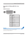
1
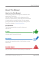
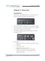
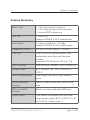
MA2CHBOX.XL
User‘s Manual
Version 1.2

Copyright
All rights reserved. Permission to reprint or electronically reproduce
any document or graphic in whole or in part for any reason is
expressly prohibited, unless prior written consent is obtained from the
DirectOut GmbH.
All trademarks and registered trademarks belong to their respective
owners. It cannot be guaranteed that all product names, products,
trademarks, requisitions, regulations, guidelines, specifications and
norms are free from trade mark rights of third parties.
All entries in this document have been thoroughly checked; however
no guarantee for correctness can be given.
DirectOut GmbH cannot be held responsible for any misleading or
incorrect information provided throughout this manual.
DirectOut GmbH reserves the right to change specifications at any time
without notice.
DirectOut Technologies® is a registered trademark of the DirectOut
GmbH.
© DirectOut GmbH, 2015
page 2 of 80
MA2CHBOX.XL Manual - Version 1.2

Table of contents
About This Manual
5
How to Use This Manual
5
Conventions5
Chapter 1: Overview
6
Introduction6
Feature Summary
7
Applications8
How it works
8
CHAPTER 2: Legal issues & facts
10
Before Installing This Device
10
First Aid (in case of electric shock)
11
Defective Parts/Modules 12
Updates12
Intended Operation 13
Conditions of Warranty
14
Conformity & Certificates
15
Contact16
Contents 17
Accessory18
Chapter 3: Installation
Installing the Device 21
21
CHAPTER 4: Operation
27
Introduction27
Global Control
28
Input / Sync
30
MA2CHBOX.XL Manual - Version 1.2
page 3 of 80

Display / Menu
32
Menu Map
42
Monitoring44
Signal Input / Output
46
Servicing / Remote Control
47
CHAPTER 5: MA2CHBOX Remote
48
Introduction48
Connecting the device
50
Overview52
Settings55
Matrix61
CHAPTER 6: Troubleshooting and Maintenance
66
Troubleshooting66
Maintenance69
CHAPTER 7: Technical Data
70
Appendix A: Wiring AES I/O, Line Out
DSUB-9 (female)
73
73
Index74
page 4 of 80
MA2CHBOX.XL Manual - Version 1.2
About This Manual
About This Manual
How to Use This Manual
This manual guides you through the installation and
operation of the device.
Use the Table of Contents at the beginning of the
manual or Index Directory at the end of the document
to locate help on a particular topic. You can access
more information and latest news by visiting on the
DirectOut website at www.directout.eu.
Conventions
The following symbols are used to draw your
attention to:
TI P S !
indicate useful tips and shortcuts.
N OT E S !
are used for important points of clarification or cross
references.
WA R N I N G S!
alert you when an action should always be observed.
MA2CHBOX.XL Manual - Version 1.2
page 5 of 80
Chapter 1: Overview
Chapter 1: Overview
Introduction
Welcome to the MA2CHBOX.XL, DirectOuts two
channel monitor for MADI and AES signals.
The MA2CHBOX.XL can monitor any mono channel
or any stereo pair of 64 audio channels from a MADI
stream or the incoming AES signal.
An internal routing matrix provides signal routing
between all I/Os.
Interfaces:
• MADI I/O (SC optical, BNC coaxial, SFP cage)
• AES3 I/O
• Line Out (stereo)
• Headphone output (stereo)
• USB Port for transmission of serial data
(‘Serial over MADI’), remote control and firmware updates.
page 6 of 80
MA2CHBOX.XL Manual - Version 1.2
Chapter 1: Overview
Feature Summary
MADI Ports
1 x SC multi-mode connectors
1 x SFP (empty cage without module)
1 x coaxial BNC connectors
AES Port
1 x AES3 I/O
(adaptor DSUB-9 to XLR male/female)
Line Output
1 x stereo, balanced, + 24 dBu
(adaptor DSUB-9 to XLR male/female)
Headphone Output
6.3 mm TRS jack, stereo, + 18 dBu
USB Port
USB 2.0 port for remote control, (de-)
embedding serial data and firmware
updates
supported OS: Windows XP, Vista, 7, 8
MADI Formats
56/64 channel, 48k/96k Frame, S/MUX 2/4
Sample Rates
44.1, 48, 88.2, 96, 176.4, 192 kHz +/12.5%
Audio Routing Matrix
Audio signal routing on a per channel
basis.
Serial Embedder
Routing
Matrix to (de-)embed and route RS-232
data.
MIDI over MADI
Routing
Matrix to route embedded MIDI data
Power Supply
This device is equipped with one wide
range power supply (84 V to 264 V AC / 47
Hz to 63 Hz / safety class 1).
MA2CHBOX.XL Manual - Version 1.2
page 7 of 80
Chapter 1: Overview
Applications
Providing 194 input channels and 198 output channels
the MA2CHBOX.XL can be used for monitoring and
signal distribution. Further it can act as (de-)embedder
of serial data.
Typical applications include:
• signal control of MADI signals within a signal chain; e.g. on stage for line check.
• external monitors - the selected channel pair for monitoring is copied to the Line out and/or AES output feeding e.g. external monitors.
• recording with redundant systems - the
incoming MADI signal is mirrored to the other
MADI outputs feeding secondary recording
systems.
• signal distribution - all I/Os are accessed via routing matrix which is controlled by a software remote.
How it works
The input is selected for each output individually in
the menu. By turning the encoder knob, the desired
channel pair is accessed or the volume adjustment is
done.
The internal routing matrix is configured by a
software remote and stored in the device.
page 8 of 80
MA2CHBOX.XL Manual - Version 1.2
Chapter 1: Overview
MA2CHBOX.XL Manual - Version 1.2
page 9 of 80
CHAPTER 2: Legal issues & facts
CHAPTER 2: Legal issues & facts
Before Installing This Device
WAR NING!
Please read and observe all of the following notes
before installing this product:
• Check the hardware device for transport damage.
• Any devices showing signs of mechanical damage or damage from the spillage of liquids must not be connected to the mains supply, or disconnected from the mains immediately by pulling out the power lead.
• All devices must be grounded. The device is grounded through its IEC power connections.
• All devices must be connected to the mains using the three-cord power leads supplied with the system. Only supply electrical interfaces with the voltages and signals described in these instructions.
• Do not use the device at extreme temperatures. Proper operation can only be guaranteed
between temperatures of 5º C and 45º C and a maximum relative humidity of 80 %, non-
condensing.
• The cabinet of the device will heat up. Do not place the device close to heating sources (e.g. heaters). Observe the environmental conditions.
page 10 of 80
MA2CHBOX.XL Manual - Version 1.2
CHAPTER 2: Legal issues & facts
First Aid (in case of electric shock)
WA R N I N G !
•
•
Do not touch the person or his/her clothing before power is turned off, otherwise you risk sustaining an electric shock yourself.
Separate the person as quickly as possible from the electric power source as follows:
-- Switch off the equipment.
-- Unplug or disconnect the mains cable.
• Move the person away from the power source by using dry insulating material (such as wood or plastic).
• If the person is unconscious:
-- Check their pulse and reanimate if their respiration is poor.
-- Lay the body down and turn it to one side. Call for a doctor immediately.
• Having sustained an electric shock, Always consult a doctor.
MA2CHBOX.XL Manual - Version 1.2
page 11 of 80
CHAPTER 2: Legal issues & facts
Defective Parts/Modules
WAR NING!
This device contains no user-serviceable parts.
Therefore do not open the device.
In the event of a hardware defect, please send the
device to your DirectOut representative together with
a detailed description of the fault.
We would like to remind you to please check
carefully whether the failure is caused by erroneous
configuration, operation or connection before sending
parts for repair.
Updates
DirectOut products are continually in development,
and therefore the information in this manual may be
superseded by new releases. To access the latest
documentation, please visit the DirectOut website:
www.directout.eu.
This guide refers to firmware version 1.5.
page 12 of 80
MA2CHBOX.XL Manual - Version 1.2
CHAPTER 2: Legal issues & facts
Intended Operation
The MA2CHBOX.XL is designed for monitoring
MADI signals (AES10) or AES signals (AES3) via
headphones or line output or AES.
Warning !
No compensation can be claimed for damages
caused by operation of this unit other than for the
intended use described above. Consecutive damages
are also excluded explicitly. The general terms and
conditions of business of DirectOut GmbH are
applied.
MA2CHBOX.XL Manual - Version 1.2
page 13 of 80
CHAPTER 2: Legal issues & facts
Conditions of Warranty
This unit has been designed and examined carefully
by the manufacturer and complies with actual norms
and directives.
Warranty is granted by DirectOut GmbH over the
period of two years for all components that are
essential for proper and intended operation of the
device. The date of purchase is applied for this period.
Consumable parts (e.g. battery) are excluded from
warranty claims.
Warning!
All claims of warranty will expire once the device
has been opened or modified, or if instructions and
warnings were ignored.
For warranty claims please contact the dealer where
your device was acquired.
page 14 of 80
MA2CHBOX.XL Manual - Version 1.2
CHAPTER 2: Legal issues & facts
Conformity & Certificates
CE
This device complies with the basic requests of
applicable EU guidelines. The appropriate procedure
for approval has been carried out.
RoHS
(Restriction of the use of certain Hazardous
Substances)
This device was constructed fulfilling the directive
on the restriction of the use of certain hazardous
substances in electrical and electronic equipment
2002/95/EC.
WEEE
(Directive on Waste Electrical and Electronic
Equipment)
Due to the directive 2002/96/EC for waste disposal
this device must be recycled.
For correct recycling please dispatch the device to:
IMM Elektronik GmbH,
Leipziger Str. 32
09648 Mittweida
Germany
Only stamped parcels will be accepted!
WEEE-Reg.-No. DE 93924963
MA2CHBOX.XL Manual - Version 1.2
page 15 of 80
CHAPTER 2: Legal issues & facts
Contact
Sales:
DirectOut GmbH, Leipziger Str. 32, 09648 Mittweida,
Germany
Phone: +49 (0)3727 99697-50 // Fax: +49 (0)3727
99697-52
www.directout.eu
Manufacturer:
IMM Elektronik GmbH, Leipziger Str. 32, 09648
Mittweida, Germany
Phone: +49 (0)3727 6205-0 // Fax: +49 (0)3727
6205-56
www.imm-gruppe.de
page 16 of 80
MA2CHBOX.XL Manual - Version 1.2
CHAPTER 2: Legal issues & facts
Contents
The contents of your MA2CHBOX.XL package
include:
• 1 x MA2CHBOX.XL
• 1 x DSUB-9 to XLR adaptor
• 1 x power chord
• 1 x Manual
To complete the delivery, download the USB serial
driver and software remote application from the
website.
Link: http://www.directout.eu
MA2CHBOX.XL Manual - Version 1.2
page 17 of 80
CHAPTER 2: Legal issues & facts
Accessory
The Line Out and AES3 I/O are available as a DSUB-9
socket.
For adaption between DSUB-9 and XLR plugs an
adaptor is offered.
DSUB-9 to XLR adaptor
Signal
XLR
Line Out L
male
Line Out R
male
AES3 input
female
AES3 output
male
Pinout DSUB-9: See „Appendix A: Wiring AES I/O,
Line Out“ on page 73.
page 18 of 80
MA2CHBOX.XL Manual - Version 1.2
CHAPTER 2: Legal issues & facts
Two different optical SFP modules are available from
DirectOut GmbH:
• Multimode SFP transceiver with LC connectors (No: 11900-129)
• Singlemode SFP transceiver with LC connectors (No: 11900-130)
Specification of the optical SFP modules:
SFP
Multimode
Singlemode
Wavelength TX
1310 nm
1310 nm
Wavelenght RX
1310 nm
1310 nm
Distance
2 km
10 km
Powerbudget (dB)
11 dB
12 dB
Protocols
Fast Ethernet OC3/
STM1
Gigabit Ethernet,
Gigabit Fibre
Channel
Bandwidth from
100 Mbit/s
1.050 Gbit/s
Bandwidth
155 Mbit/s
1.250 Gbit/s
Laser
FP
FP
Receiver Type
PIN
PIN
Connector
LC
LC
Wavelength TX min
1260 nm
1260 nm
Wavelength TX max
1360 nm
1360 nm
MA2CHBOX.XL Manual - Version 1.2
page 19 of 80
CHAPTER 2: Legal issues & facts
SFP
Multimode
Singlemode
Wavelength RX min
1260 nm
1260 nm
Wavelength RX max
1620 nm
1600 nm
Transmit min
- 19.00 dBm
- 9.00 dBm
Transmit max
- 14.00 dBm
- 3.00 dBm
Receive min
- 30 dBm
- 21.00 dBm
Receive max
(Receiver overload)
- 5.00 dBm
- 3.00 dBm
Temperature (min)
0° Celsius
0° Celsius
Temperature (max)
70° Celsius
70° Celsius
Type of DDM/DOM
internal
internal
Extinction Ratio
8.20 dB
9 dB
page 20 of 80
MA2CHBOX.XL Manual - Version 1.2
Chapter 3: Installation
Chapter 3: Installation
Installing the Device
1. Open the packaging and check that the contents have been delivered complete and undamaged.
2.Place the device on a non-slip horizontal surface. The delivered pads may be affixed to the bottom of the cabinet. Ensure a clean and dry surface before affixing the pads.
Warning
The synthetics of the delivered pads might cause
stains on damageable surfaces. To avoid staining
of furniture surfaces it is recommended to place a
protective plate under the device.
Warning
Avoid damage from condensation by waiting for the
device to adapt to the environmental temperature.
Proper operation can only be guaranteed between
temperatures of 5º C and 45º C and a maximum
relative humidity of 80%, non-condensing.
Ensure that the unit has sufficient air circulation for
cooling.
MA2CHBOX.XL Manual - Version 1.2
page 21 of 80
Chapter 3: Installation
3.Remove the protective cap from the optical
MADI port(s) before use.
NOT E !
Retain the protective cap if the optical port is
unused. This will protect against soiling which can
lead to malfunction.
4.Connect signal cable(s) for the MADI signals.
page 22 of 80
MA2CHBOX.XL Manual - Version 1.2
Chapter 3: Installation
5.Connect the signal cables for the analog and AES3 audio signals to the DSUB-9 adaptor. Connect the adaptor to the DSUB-9 plug at the rear panel.
The adaptor converts from DSUB-9 (male) to:
• 2 x XLR male (Line Out L/R)
• 1 x XLR male (AES3 output)
• 1 x XLR female (AES3 input).
WA R N I N G !
Do not connect voltage sources to the analog
outputs. This may cause damage at the output
stages. Observe the technical specifications listed in
this document.
MA2CHBOX.XL Manual - Version 1.2
page 23 of 80
Chapter 3: Installation
Warning
The line output is not servo balanced. Do not
connect the negative lead to ground. This may cause
damage at the output stage. Observe the technical
specifications listed in this document.
6.Optional: Connect an USB cable to the USB port for remote control or firmware updates. This requires the USB Serial driver (Windows) being installed first. The driver and the installation instructions are available at
www.directout.eu.
7. Using the power cord provided connect the PSU to a matching power supply:
Warning
This device must be connected to the mains using
the three-cord power leads supplied with the system.
Only supply the voltages and signals indicated
(84 V – 264 V).
page 24 of 80
MA2CHBOX.XL Manual - Version 1.2
Chapter 3: Installation
8.Turn on the power switch:
While the device is booting the currently installed
firmware is indicated in the display - e.g. firmware
version 1.5.
TI P
Use the DirectOut Release Map to match your
DirectOut device with the latest firmware or software
release.
Link: http://www.directout.eu/upload/dokumente/
dotec_release_map.pdf
Note
To update the firmware an installed USB serial driver
(Windows) and the Update Tool are necessary. The
software and the installation instructions are available
at www.directout.eu.
MA2CHBOX.XL Manual - Version 1.2
page 25 of 80
Chapter 3: Installation
9.Installation of USB Serial driver
• download the USB Serial driver
• download the ‘Installation Guide for USB Control
• follow the installation instructions in the ‘Installation Guide for USB Control’
T IP
Keep any packaging in order to protect the device
should it need to be dispatched for service.
page 26 of 80
MA2CHBOX.XL Manual - Version 1.2
CHAPTER 4: Operation
CHAPTER 4: Operation
Introduction
This chapter describes the basic operation of the
device.
Note that throughout this manual, the abbreviation FS
refers to sample rate or sample frequency. So, when
dealing with scaling factors, the following sample
rates can be written as:
• 44.1kHz or 48kHz = 1 FS
• 88.2kHz or 96kHz = 2 FS
• 176.4kHz or 192kHz = 4 FS
MA2CHBOX.XL Manual - Version 1.2
page 27 of 80
CHAPTER 4: Operation
Global Control
Power
C13 socket
Connect the power supply here
(84 - 264 V AC).
N OT E
The display indicates that a working power supply
is connected to the power supply unit. Note that
an unlit display does not guarantee that the device
is free of voltage. To ensure that the device is
completely disconnected from mains voltage, the
power chord(s) must be disconnected.
page 28 of 80
MA2CHBOX.XL Manual - Version 1.2
CHAPTER 4: Operation
Power
1 Switch
Enable / disable power supply.
Volume*
1 Encoder
Press and turn for all operations
(channel selection, volume, menu
settings).
Press short to toggle between
volume and channel selection
(Vol/Ch) or to navigate through the
menu.
Press for more than 2 seconds
to toggle between Vol/Ch and the
menu.
Press twice (“double click”) to
mute / unmute the output. Turning
the encoder knob at volume
selection will also unmute the
output
* Mute is available for the outputs Headphones, Line
Out and AES. It is applied only to outputs that are
set to ‘Encoder’ (‘E’) in the menu - see section ‘Level
Settings’ on page 40.
MA2CHBOX.XL Manual - Version 1.2
page 29 of 80
CHAPTER 4: Operation
Input / Sync
Input
Four inputs are available:
• MADI - SC optical
• MADI - BNC coaxial
• MADI - SFP cage
• AES - DSUB-9 adaptor
Sync
The device is clocked according the setting specified
in the menu.
See S <x> (MENU) on page 38.
NOT E
Auto Sync - if only one signal is connected, it will be
used as clock source ignoring the sync setting.
page 30 of 80
MA2CHBOX.XL Manual - Version 1.2
CHAPTER 4: Operation
SYNC
SC
BNC
SFP
AES
LED (green) - indicates sync status
of the <SC> / <BNC> / <SFP> /
<AES> input.
LED OFF
= no signal
LED flashing= signal present, asynchronous (LOCK)
LED ON
= signal present, synchronous (SYNC)
If no input detects a valid signal, all four LEDs will
pulse.
MA2CHBOX.XL Manual - Version 1.2
page 31 of 80
CHAPTER 4: Operation
Display / Menu
The 7 segment display indicates the selected channel
pair, adjusted volume, level, menu settings.
The display is used in two modes:
• idle mode - volume (or channel) selection or
level metering
• menu mode - menu settings
After a short period of time without using the
encoder knob the idle mode becomes active;
i.e. the menu is left automatically and the display
switches back to
level metering or vol (or channel) selection.
NOT E
Firmware 1.3 (Q4/2014) introduces a default setting
for either channel or volume selection in idle mode see „Idle Mode“ on page 34.
page 32 of 80
MA2CHBOX.XL Manual - Version 1.2
CHAPTER 4: Operation
Number
&
Decimal
Point(s)
Number
The selected channel (pair) is
indicated.
In stereo mode odd numbers are
indicated only; e.g. <05.> is selected
= monitoring of MADI channels 05 (left)
and 06 (right)
In mono mode all channels are indicated.
Blinking of left decimal point indicates:
Mute active.
Blinking numbers indicate:
channel not available
(at scaling factor 2 FS or 4 FS or in 56ch
mode)
The adjusted volume level is
indicated.
The signal can be varied within a range
of -96 dBFS to 0 dBFS in steps of 1 dB.
An additional boost up to 9 dB can be
applied.
Blinking numbers indicate: Mute active.
MA2CHBOX.XL Manual - Version 1.2
page 33 of 80
CHAPTER 4: Operation
Idle Mode
To change default encoder selection in idle mode:
• switch off / on device
• push encoder knob during firmware display
• the selection is indicated by the right decimal point
idle channel
idle volume
This setting is also available in the software remote.
page 34 of 80
MA2CHBOX.XL Manual - Version 1.2
CHAPTER 4: Operation
MA2CHBOX.XL Manual - Version 1.2
page 35 of 80
CHAPTER 4: Operation
Push the encoder knob for more than 2 seconds
to enter the menu.
Signal Routing
Display
Meaning
h <x>
Selected audio input for
headphones out.
Values: o = SC input / b = BNC input /
c = SFP input / A = AES input / M = matrix
L <x>
Selected audio input for line out
Values: o = SC input / b = BNC input /
c = SFP input / A = AES input / M = matrix
A <x>
Selected audio input for AES out.
Values: o = SC input / b = BNC input /
c = SFP input / A = AES input / M = matrix
o <x>
Selected audio input for SC optical
out.
Values: o = SC input / b = BNC input /
c = SFP input / A = AES input* / M = matrix
b <x>
Selected audio input for BNC
coaxial out.
Values: o = SC input / b = BNC input /
c = SFP input / A = AES input* / M = matrix
c <x>
Selected audio input for SFP
output.
Values: o = SC input / b = BNC input /
c = SFP input / A = AES input* / M = matrix
page 36 of 80
MA2CHBOX.XL Manual - Version 1.2
CHAPTER 4: Operation
* Firmware 1.3 introduces AES input as source for
the MADI outputs.
Selecting <A> for the MADI outputs (parameter
<o>, <b>, <c>) will feed the two AES input channels
alternately to all MADI output channels.
N OT E
The software remote offers access to more settings:
• matrix channel based signal routing (M)
• channel mode for the output signal
• frame format for the output signal @ 2 FS
• bit-transparent processing of AES input signal
• configuration of serial embedder routing
• routing of MIDI over MADI data
MA2CHBOX.XL Manual - Version 1.2
page 37 of 80
CHAPTER 4: Operation
System Settings
Display
Meaning
F <x>
Selected input scaling factor.*
Values: 1 = 1 FS / 2 = 2 FS / 4 = 4 FS
S <x>
Sync Source**
Values: o = SC input / b = BNC input / c =
SFP input / A = AES input
C <x>
Monitor mode is indicated.***
Values: 1 = mono / 2 = stereo
d <x>
Level metering (display) during idle
mode.****
Values: 0 = off / 1 = on
* A 96k Frame signal at the input that is defined
as clock source will override the setting and force
the scaling factor to 2 FS temporarily. The set value
is restored once a 48k Frame signal is detected.
Override is indicated by blinking display of 1 FS or
4 FS.
** If only one input is locked the setting is ignored
and this input is used as clock source.
page 38 of 80
MA2CHBOX.XL Manual - Version 1.2
CHAPTER 4: Operation
*** Monitoring of either a stereo pair or a single
mono channel.
Stereo => odd channels to left and even channels to
right.
Mono => left and right are identical.
This setting affects the indication of channels too
(see <Numbers> + Decimal points).
Using AES as input source (<AA>) will override the
setting and force to stereo temporarily.
**** After a short period of time without using the
encoder knob the idle mode is activated.
The display then indicates the input level for the left
and right channel individually. The three horizontal
bars of the segment display mark the values
-30 dBFS, -18 dBFS and -6 dBFS.
The decimal point indicates a signal different from
digital zero.
MA2CHBOX.XL Manual - Version 1.2
page 39 of 80
CHAPTER 4: Operation
Level Settings*
Display
Meaning
h <x>
Level of headphones out
Values: E = encoder, output level variable
(follows the volume setting)
L <x>
Level of Line out
Values: F = fixed, output level fixed
E = encoder, output level variable
(follows the volume setting)
A <x>
Level of AES out
Values: F = fixed, output level fixed
E = encoder, output level variable
(follows the volume setting)
* If the value is set to ‘E’ (= Encoder) the output will
mute if the encoder is pressed twice.
page 40 of 80
MA2CHBOX.XL Manual - Version 1.2
CHAPTER 4: Operation
MA2CHBOX.XL Manual - Version 1.2
page 41 of 80
CHAPTER 4: Operation
Menu Map
Volume
Channel
Press > 2 s
Press > 2 s
Press to navigate.
Turn to adjust.
Doubleclick for mute /
unmute.
page 42 of 80
h <x>
headphones
o = SC
b = BNC
c = SFP
A = AES
M = Matrix
L <x>
Line Out
o = SC
b = BNC
c = SFP
A = AES
M = Matrix
A <x>
AES out
o = SC
b = BNC
c = SFP
A = AES
M = Matrix
o <x>
SC optical Out
o = SC
b = BNC
c = SFP
A = AES
M = Matrix
b <x>
BNC Out
o = SC
b = BNC
c = SFP
A = AES
M = Matrix
c <x>
SFP Out
o = SC
b = BNC
c = SFP
A = AES
M = Matrix
MA2CHBOX.XL Manual - Version 1.2
CHAPTER 4: Operation
F <x>
Scaling Factor
S <x>
Sync Priority
C <x>
Monitor Mode
d <x>
Display
1 = 1 FS
2 = 2 FS
4 = 4 FS
o = SC
b = BNC
c = SFP
A = AES
1 = mono
2 = stereo
h <x>
headphones
level
L <x>
Line level
A <x>
AES level
E = Encoder
E = Encoder
F = fixed
E = Encoder
F = fixed
0 = level display off
1 = level display on
MA2CHBOX.XL Manual - Version 1.2
page 43 of 80
CHAPTER 4: Operation
Monitoring
Three outputs with individual volume settings are
available:
1
2
page 44 of 80
3
1
Phones
6.3 mm TRS jack, stereo
Connect the headphones here to
monitor the selected single channel
or the selected channel pair.
2
Line Out
2 x XLR connector (male)
Requires connected DSUB-9
adaptor at the rear panel.
3
AES Out
1 x XLR connector (male)
Requires connected DSUB-9
adaptor at the rear panel.
MA2CHBOX.XL Manual - Version 1.2
CHAPTER 4: Operation
2
3
DSUB-9 to XLR adaptor
Signal
XLR
Line Out L
male
Line Out R
male
AES3 input
female
AES3 output
male
Pinout DSUB-9: See „Appendix A: Wiring AES I/O,
Line Out“ on page 73.
MA2CHBOX.XL Manual - Version 1.2
page 45 of 80
CHAPTER 4: Operation
Signal Input / Output
1
2
1
2
3
4
4
3
BNC
OUT / IN
2 x BNC socket (coaxial)
OUT: MADI output (64 ch), connect for MADI output signal here.
IN: MADI input (64 ch), connect MADI input signal here.
SFP
1 x SFP cage*
Insert SFP module here and
connect MADI input/output
SC
OUT / IN
2 x SC socket (optical)
OUT: MADI output (64 ch), connect for MADI output signal here.
IN: MADI input (64 ch), connect MADI input signal here.
AES I/O
LINE OUT
1 x DSUB-9 connector
(female)
Connect delivered DSUB-9 adaptor
here for XLR connection of AES I/O
and Line Out.
*empty cage, module not included in delivery
See „Accessory“ on page 18.
page 46 of 80
MA2CHBOX.XL Manual - Version 1.2
CHAPTER 4: Operation
WA R N I N G !
Only use the delivered adaptor or observe correct pin
assignment - see “Appendix A: Wiring AES I/O, Line
Out” on page 73.
Servicing / Remote Control
An integral USB port is used for firmware updates
and remote control.
USB
USB 2.0 socket (Type B)
Connect here for firmware
updates and remote control.
N OT E
For USB control please read the guide “Installation
USB control”. See: www.directout.eu
MA2CHBOX.XL Manual - Version 1.2
page 47 of 80
CHAPTER 5: MA2CHBOX Remote
CHAPTER 5: MA2CHBOX Remote
Introduction
The software application ‘MA2CHBOX Remote’
offers access to all settings of the device. Some
features are accessible exclusively via the remote
application:
• matrix channel based signal routing (M)
• adjustable channel mode for the output signal
• adjustable frame format for the output signal @ 2 FS
• bittransparent processing of AES input signal
• configuration of serial embedder routing
• routing of MIDI over MADI data
Requirements
• OS version Windows® XP, Vista, 7, 8, 10
• DirectOut USB Serial driver installed
• Firmware version 1.5 or higher
NOT E
The driver and installation instructions are available at
www.directout.eu.
All settings are stored inside the device. Presets
can be stored and recalled for quick configuration
changes.
page 48 of 80
MA2CHBOX.XL Manual - Version 1.2
CHAPTER 5: MA2CHBOX Remote
The overview informs about the input signal state and
offers access to the clock setting, signal routing and
the volume level and channel selection.
Click SETTINGS to access the settings of the
device, the serial embedder and the MADI output
format.
Click MATRIX to access the routing matrix for
individual assembling of the audio signal routing.
MA2CHBOX.XL Manual - Version 1.2
page 49 of 80
CHAPTER 5: MA2CHBOX Remote
Connecting the device
Remote control is available via two different methods:
a) Serial data via USB
b) Serial over MADI (embedded RS-232 data)
The USB Serial driver is required for method a) only.
However, it is required to have the driver installed
anyway for initial setup and as fallback once a cabling
or other issue interrupts the communication via the
MADI link.
To connect the device via USB:
• Go to ‘Command’ and ‘Select Serial COM port’
• Click Connect or use the connect button
page 50 of 80
MA2CHBOX.XL Manual - Version 1.2
CHAPTER 5: MA2CHBOX Remote
Remote control via method b) needs a looped
MADI connection with the connected device(s) for
bidirectional communication and appropriate settings
of the serial embedder matrix.
See „Settings“ on page 55 for information about
the serial embedder matrix.
N OT E
In case of a communication loss via MADI link you
may reset the serial embedder matrix to regain
access via the local USB port.
MA2CHBOX.XL Manual - Version 1.2
page 51 of 80
CHAPTER 5: MA2CHBOX Remote
Overview
Signal State
SYNC
Information about lock / sync state
of input signal.
MODE
Individual display of MADI input
signal format (frame format and
channel mode).
CLOCK
SOURCE
Pulldown menu to select clock
source.
CLOCK
RANGE
Pulldown menu to select scaling
factor.
SAMPLE
RATE
Display of the base rate of the
device clock.
For information about the parameters please refer to
„CHAPTER 4: Operation“ on page 27.
page 52 of 80
MA2CHBOX.XL Manual - Version 1.2
CHAPTER 5: MA2CHBOX Remote
Audio Source
SC
Pulldown menu to select signal
source for SC optical output.
BNC
Pulldown menu to select signal
source for BNC coaxial output.
SFP
Pulldown menu to select signal
source for SFP output.
AES
Pulldown menu to select signal
source for AES3 output.
LineOut
Pulldown menu to select signal
source for analog line output.
Phones
Pulldown menu to select signal
source for headphones output.
For information about the parameters please refer to
„CHAPTER 4: Operation“ on page 27.
MA2CHBOX.XL Manual - Version 1.2
page 53 of 80
CHAPTER 5: MA2CHBOX Remote
Volume / Channel
VOLUME
Display of volume setting. Arrow
keys to increase (UP) or decrease
(DOWN) volume level.
MUTE
Checkbox to mute / unmute all
outputs that are set to ‘encoder’.
CHANNEL
Display of channel selection of the
MADI signal for the headphones,
line out and AES output.
Arrow keys to increase (UP)
or decrease (DOWN) numeric
selection.
STEREO
MODE
Checkbox to toggle between
stereo or mono mode.
For information about the parameters please refer to
„CHAPTER 4: Operation“ on page 27.
page 54 of 80
MA2CHBOX.XL Manual - Version 1.2
CHAPTER 5: MA2CHBOX Remote
Settings
Device settings
Idle Mode
Pulldown menu to set the idle
mode to either volume level or
channel selection.
Show
Levelmeter
Checkbox to toggle level meter
display on or off in idle mode.
Transparent
Mode (AES)
Checkbox to toggle bittransparency of AES input to
MADI output and vice versa.*
Line Output
Levels
Pulldown menu to set the line
output to a fixed level or to
follow the encoder setting.
AES Output
Levels
Pulldown menu to set the AES3
output to a fixed level or to
follow the encoder setting.
* This setting may interfere with a connection
method using the MADI link.
MA2CHBOX.XL Manual - Version 1.2
page 55 of 80
CHAPTER 5: MA2CHBOX Remote
Serial Embedder Routing
Baud Rate
Pulldown menu to select
the transfer rate of the serial
communication.
Values: 115200 / 38400 / 19200 baud
Remote In
Pulldown menu to select signal
port for incoming control data.
Values:USB / SC / BNC / SFP
SC UART
Out
Pulldown menu to select signal
source of outgoing control data at
the SC output.
Values:SC / BNC / SFP / USB / Remote In / off
In case of a communication loss via MADI link you
may reset the serial embedder matrix to regain access via the local USB port - see page 51.
page 56 of 80
MA2CHBOX.XL Manual - Version 1.2
CHAPTER 5: MA2CHBOX Remote
BNC UART
Out
Pulldown menu to select signal
source of outgoing control data at
the BNC output.
Values:SC / BNC / SFP / USB / Remote In / off
SFP UART
Out
Pulldown menu to select signal
source of outgoing control data at
the SFP output.
Values:SC / BNC / SFP / USB / Remote In / off
USB UART
Out
Pulldown menu to select signal
source of outgoing control data at
the USB port.
Values:SC / BNC / SFP / USB / Remote In
Scheme
Remote In
USB
SC
BNC
SFP
UART
Out
UART
Out
SC
UART
Out
UART
Out
MA2CHBOX.XL Manual - Version 1.2
USB
BNC SFP
page 57 of 80
CHAPTER 5: MA2CHBOX Remote
MIDI over MADI Routing
SC Out
Pulldown menu to select signal
port of outgoing MIDI data at the
SC output.
Values: off / SC / BNC / SFP
BNC Out
Pulldown menu to select signal
port of outgoing MIDI data at the
BNC output.
Values: off / SC / BNC / SFP
SFP Out
Pulldown menu to select signal
port of outgoing MIDI data at the
SFP output.
Values: off / SC / BNC / SFP
MIDI over MADI means that the MIDI data is carried
by user bit of audio channel 56.
The MIDI matrix allows to distribute or route the
embedded MIDI data between the three MADI I/Os.
However, it does not embed an external MIDI signal
into a MADI stream or deembed from an incoming
MADI stream.
page 58 of 80
MA2CHBOX.XL Manual - Version 1.2
CHAPTER 5: MA2CHBOX Remote
Scheme
SC
BNC
SFP
SC
BNC SFP
N OT E
The output selection ‘off’ - in both serial embedder
and MIDI matrix - means that the user bits of the
incoming MADI signals stick with the routed audio
signal.
Exception: Transparent Mode (AES) active is used
- see page 55.
Serial over MADI: user bit audio channel 1 to 9
MIDI over MADI: user bit audio channel 56
MA2CHBOX.XL Manual - Version 1.2
page 59 of 80
CHAPTER 5: MA2CHBOX Remote
Output Format
SC Out
BNC Out
SFP Out
56ch
Checkbox to toggle the channel
mode of the MADI output signal
between 56 ch and 64 ch.
SC Out
BNC Out
SFP Out
96k Frame
Checkbox to toggle the frame
format of the MADI output
signal between 48k Frame and
96k Frame.*
* 96k Frame is available at 2 FS operation only.
page 60 of 80
MA2CHBOX.XL Manual - Version 1.2
CHAPTER 5: MA2CHBOX Remote
Matrix
The routing matrix offers access to single channel
level of each I/O. To use the adjusted routing select
‚Matrix‘ as audio source in the overview.
Inputs are arranged vertically, outputs horizontally.
MA2CHBOX.XL Manual - Version 1.2
page 61 of 80
CHAPTER 5: MA2CHBOX Remote
The different I/Os are organized in pages. So there
are seven input pages and seven output pages.
The MADI I/Os are split into portions of 32 channels
each to suit a better overview.
page 62 of 80
Input
SC 1..32
SC 33..64
BNC 1..32
BNC 33..64
SFP 1..32
SFP 33..64
AES
Button to access the page of the
particular input port.
Example:
SC 1..32 = SC port
channel 1 to 32
SC 33..64= SC port
channel 33 to 64
AES
= AES3 port
channel 1/2
Output
SC 1..32
SC 33..64
BNC 1..32
BNC 33..64
SFP 1..32
SFP 33..64
AES/LINE
Button to access the page of the
particular output port.
Example:
SC 1..32 = SC port
channel 1 to 32
SC 33..64= SC port
channel 33 to 64
AES/LINE= AES3 port &
LineOut & Phones channel 1/2
MA2CHBOX.XL Manual - Version 1.2
CHAPTER 5: MA2CHBOX Remote
Setting / deleting crosspoints
• move the cursor to the desired position - a small green square and transparent bars point the active position
• click into the square to set / delete the crosspoint
To set more than one crosspoint you may click and
hold the left mouse button and move the cursor. The
pointed crosspoints will be set upon release of the
mouse button.
crosspoint - output is set on the
selected input page.
crosspoint - output is set on a nonselected input page.
MA2CHBOX.XL Manual - Version 1.2
page 63 of 80
CHAPTER 5: MA2CHBOX Remote
Presets
The settings of the device and routing matrix can be
stored to a single file. The settings can be reloaded
separately from the same file. This allows to use the
settings independently from each other; e.g. you may
reload another routing setup without changing the
clock source.
page 64 of 80
Save...
Stores all settings in one file
(.mbx).
Load
Settings...
Restores all device settings
except the routing matrix.
Load
Matrix...
Restores the setting of the routing
matrix only.
Load all...
Restores all settings including
routing matrix.
MA2CHBOX.XL Manual - Version 1.2
CHAPTER 5: MA2CHBOX Remote
MA2CHBOX.XL Manual - Version 1.2
page 65 of 80
CHAPTER 6: Troubleshooting and Maintenance
CHAPTER 6: Troubleshooting and
Maintenance
Troubleshooting
To identify a possible defect with the device please
consult the following table.
If the fault cannot be resolved using these
instructions, please contact your local DirectOut
representative or visit support.directout.eu.
Issue
Possible
reason
Solution
Device
doesn’t work.
Power supply is
broken.
Check that the power supply
switch is on, that the device
is connected to the power
supply and that the socket is
working. Defective fuses must
be exchanged by qualified
service personal only.
Optical port
does not
work.
Optic is dirty.
Use an air supply to carefully
remove any dust.
Never use objects for
cleaning.
No signal at
the output
port.
Connections
(input / output)
are mixed up.
Check the connections
and change the cables if
necessary.
Check the routing matrix.
page 66 of 80
MA2CHBOX.XL Manual - Version 1.2
CHAPTER 6: Troubleshooting and Maintenance
Issue
Possible
reason
Solution
No signal at
the output
port.
Signal cable
defective.
Exchange the signal cable.
No signal at
the output
port.
Connectors of
the signal cable
are dirty.
Use an air supply to carefully
remove any dust.
Never use objects for
cleaning.
or
Exchange the signal cable.
MADI signal
at the input is
not stable.
Signal source is
defective
or
bad signal
condition (Jitter >
1 ns) - e.g. due to
exceeded length
or bad screening
attenuation of
signal cable.
Change the source
or
use appropriate cables.
Clicks in the
audio signal.
Input source is
not in sync with
clock master of
the box.
Check the status of input LED
and check clock setting of the
connected device.
MA2CHBOX.XL Manual - Version 1.2
page 67 of 80
CHAPTER 6: Troubleshooting and Maintenance
Issue
Possible
reason
Solution
Input LED
is always
blinking.
Input signal is
not in sync with
device
or
input signal is not
stable
or
bad signal
condition (Jitter >
1 ns) - e.g. due to
exceeded length
or bad screening
attenuation of
signal cable.
Change the source
or
use appropriate cables.
Display
blinking in CH
selection.
Channel is not
available, due
to scaling factor
or 56 ch mode
used.
Check the scaling factor in the
menu
or
check the input signal.
Display is
black.
No signal is
present and level
meter during idle
mode is enabled.
Check input signal
or
switch off level meter
(see page 42).
page 68 of 80
MA2CHBOX.XL Manual - Version 1.2
CHAPTER 6: Troubleshooting and Maintenance
Maintenance
To clean the device, use a soft, dry cloth. To protect
the surface, avoid using cleaning agents.
N OT E
The device should be disconnected from the power
supply during the cleaning process.
MA2CHBOX.XL Manual - Version 1.2
page 69 of 80
CHAPTER 7: Technical Data
CHAPTER 7: Technical Data
Dimensions
• Width 140 mm
• Height 42 mm
• Depth 146 mm
Weight
• 0.8 kg
Power Consumption
• 5 W (typical)
Power Supply
• 84 V - 264 V AC / 47 Hz - 63 Hz / Safety class 1
Environmental Conditions
• Operating temperature +5°C up to +45°C
• Relative humidity: 10% - 80%, non condensing
MADI Port SC optical
• 1 x SC socket FDDI (input / output)
• ISO/IEC 9314-3
• Wave length 1310 nm
• Multi-Mode 62.5/125 or 50/125
MADI Port BNC coaxial
• 2 x BNC socket (input / output)
• Impedance: 75 Ω
• 0.3 V up to 0.6 V (peak to peak)
page 70 of 80
MA2CHBOX.XL Manual - Version 1.2
CHAPTER 7: Technical Data
MADI Port SFP
• 1 x SFP (empty cage without module)
Sample Rate
• 30 - 50 kHz @1 FS
• 60 - 100 kHz @ 2 FS
• 120 - 200 kHz @ 4FS
MADI Format (I/O)
• 48k Frame, 96k Frame
• 56 channel, 64 channel
AES3 I/O
• 1 x DSUB-9 (adaptor to XLR included in delivery)
• AES3 balanced (input / output)
Phones
• 1 x TRS jack 6.3 mm (stereo)
• Level: +18 dBu
• SNR: -114.2 dB / -117.1 dBA
• THD+N: -103 dB
• THD: -106 dB
MA2CHBOX.XL Manual - Version 1.2
page 71 of 80
CHAPTER 7: Technical Data
Line Output
• 1 x DSUB-9 (adaptor to XLR included in delivery)
• balanced output
• Level: +24 dBu
• SNR: -114.5 dB / -117.3 dBA
• THD+N: -105.5 dB
• THD: -108 dB
Warning
Do not connect voltage sources to the analog
outputs. This may cause damage at the output
stages.
Warning
The line output is not servo balanced. Do not connect
the negative lead to ground. This may cause damage
at the output stage.
USB
• 1 x USB socket (Type B)
• for embedding / de-embedding of serial data, firmware updates and remote control
• Serial UART (universal asynchronous receiver/
transmitter)
• virtual COM-Port for Windows XP, Vista, 7, 8, 10
page 72 of 80
MA2CHBOX.XL Manual - Version 1.2
Appendix A: Wiring AES I/O, Line Out
Appendix A: Wiring AES I/O, Line
Out
DSUB-9 (female)
5
4
9
3
8
2
7
1
6
Pin
Signal
1
AES RX +
2
AES TX+
3
GND
4
Line Out L -
5
Line Out R -
6
AES RX -
7
AES TX -
8
Line Out L+
9
Line Out R+
N OT E !
The pinout does not comply with the adaptor
delivered with MA2CHBOX.XT.
MA2CHBOX.XL Manual - Version 1.2
page 73 of 80
Index
Index
A
Accessory............................ 18
Adaptor............................... 23
AES to MADI...................... 37
C
Conformity & Certificates
CE....................................
RoHS...............................
WEEE..............................
Contact................................
Contents..............................
Conventions..........................
15
15
15
16
17
5
D
Defective Parts/Modules..... 12
Dimensions......................... 70
DSUB-9
Adaptor...................... 18, 23
Pinout............................. 73
I
Idle mode............................ 32
Intended Operation.............. 13
L
Level metering.................... 38
M
MADI formats....................... 7
Menu Map.......................... 42
MIDI over MADI Routing.... 58
O
Output
balanced................... 24, 72
P
Power supply........................ 7
R
Remote Control.................. 47
F
Firmware............................ 25
First Aid............................... 11
S
Sample rates......................... 7
Scaling Factor..................... 27
Serial Embedder Routing.... 56
Reset.............................. 51
SFP Modules....................... 19
Support............................... 66
Sync.................................... 30
page 74 of 80
MA2CHBOX.XL Manual - Version 1.2
E
Encoder - default selection.. 34
Environmental conditions. 21, 70
Index
T
Technical data..................... 70
Troubleshooting.................. 66
U
Updates............................... 12
USB control........................ 47
W
Warranty.............................. 14
MA2CHBOX.XL Manual - Version 1.2
page 75 of 80
Notes
page 76 of 80
MA2CHBOX.XL Manual - Version 1.2
Notes
MA2CHBOX.XL Manual - Version 1.2
page 77 of 80
Notes
page 78 of 80
MA2CHBOX.XL Manual - Version 1.2
Notes
MA2CHBOX.XL Manual - Version 1.2
page 79 of 80
DirectOut GmbH
Leipziger Strasse 32
09648 Mittweida
Germany
T: +49-3727-99697-50
F: +49-3727-99697-52
www.directout.eu