1
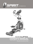
XE195 ELLIPTICAL
OWNER’S MANUAL
PLEASE CAREFULLY READ THIS ENTIRE MANUAL BEFORE
OPERATING YOUR NEW ELLIPTICAL!
SPT0057
Table Of Contents
Important Safety Instructions……………………………………………...3
Important Electrical Instructions…………………………………………..4
Important Operation Instructions………………………………………….4
Assembly Instructions…………………………………………..................5
Product Features………………………………………………….……….11
Operation of Your Console………...…………………………………..…12
Programmable Features………………………………………….…..…..15
Using A Heart Rate Transmitter…………………………………………..20
General Maintenance……………………………………………………...22.
Exploded View Diagram…………………………………………………...23
Parts List…………………………………………………………………….24
ATTENTION
This elliptical is intended for residential use only and is warranted for this application.
Any other application voids this warranty in its entirety.
XE195/SPT0057_ver.A
2
Important Safety Instructions
WARNING - Read all instructions before using this appliance.
DANGER - To reduce the risk of electric shock disconnect your elliptical from the electrical
outlet prior to cleaning and/or service work.
WARNING - To reduce the risk of burns, fire, electric shock, or injury to persons, install the
elliptical on a flat level surface with access to a 230-volt, 10-amp grounded outlet with only
the elliptical plugged into the circuit.
DO NOT USE AN EXTENSION CORD UNLESS IT IS A 18AWG OR BETTER, WITH
ONLY ONE OUTLET ON THE END:
1.
Do not operate elliptical on deeply padded, plush or shag carpet. Damage to both
carpet and elliptical may result.
2. Keep children away from the elliptical. There are obvious pinch points and other
caution areas that can cause harm.
3. Keep hands away from all moving parts.
4. Never operate the elliptical if it has a damaged cord or plug. If the elliptical is not
working properly, call your dealer.
5. Keep the cord away from heated surfaces.
6. Do not operate where aerosol spray products are being used or where oxygen is
being administered. Sparks from the motor may ignite a highly gaseous environment.
7. Never drop or insert any object into any openings.
8. Do not use outdoors.
9. To disconnect, turn all controls to the off position, then remove the plug from the
outlet.
10. Do not attempt to use your elliptical for any purpose other than for the purpose it is
intended.
11. The hand pulse sensors are not medical devices. Their purpose is to provide you with
an approximate measurement in relation to your target heart rate. Use of a chest
transmitter strap is a much more accurate method of heart rate analysis. Various
factors, including the user’s movement, may affect the accuracy of heart rate
readings. The pulse sensors are intended only as exercise aids in determining heart
rate trends in general.
12. Wear proper shoes. High heels, dress shoes, sandals or bare feet are not suitable for
use on your elliptical. Quality athletic shoes are recommended to avoid leg fatigue.
SAVE THESE INSTRUCTIONS - THINK SAFETY!
3
Important Electrical Instructions
WARNING!
NEVER remove any cover without first disconnecting AC power. lf voltage varies by ten
percent (10%) or more, the performance of your elliptical may be affected. Such
conditions are not covered under your warranty. If you suspect the voltage is low, contact
your local power company or a licensed electrician for proper testing.
NEVER expose this elliptical to rain or moisture. This product is NOT designed for use
outdoors, near a pool or spa, or in any other high humidity environment. The operating
temperature specification is 40 to 120 degrees Fahrenheit, and humidity is 95
non-condensing (no water drops forming on surfaces).
Important Operation Instructions
NEVER operate this elliptical without reading and completely understanding the
results of any operational change you request from the computer.
Understand that changes in resistance do not occur immediately. Set your desired
resistance level on the computer console and release the adjustment key. The
computer will obey the command gradually.
NEVER use your elliptical during an electrical storm. Surges may occur in your
household power supply that could damage elliptical components. Unplug the
elliptical during an electrical storm as a precaution.
Use caution while participating in other activities while pedaling on your elliptical;
such as watching television, reading, etc. These distractions may cause you to lose
balance which may result in serious injury.
Do not use excessive pressure on console control keys. They are precision set to
function properly with little finger pressure.
4
Assembly Instructions
PRE-ASSEMBLY
1.
2.
3.
Using a razor knife (Box Cutter), cut the banding straps that wrap around the carton. Reach under the
bottom edge of the car ton and pull it away from the cardboard underneath, separating the staples that
join the two together. Lift the box over the unit and unpack.
Carefully remove all parts from car ton and inspect for any damage or missing parts. If damaged parts
are found, or parts are missing, contact your dealer immediately.
Locate the hardware package. The hardware is separated into four steps. Remove the tools first.
Remove the hardware for each step as needed to avoid confusion. The numbers in the instructions
that are in parenthesis (#) are the item number from the assembly drawing for reference.
Assembly Tools
#177. Combination M5 Allen Wrench &
Phillips Head Screw Driver (1 pc)
#157. Phillips Head Screw Driver (1 pc)
#158. 12/14m/m Wrench (1 pc)
#155. 13/14m/m Wrench (1 pc)
5
STEP 1: Rail Assembly & Console Mast
1. Locate the Console Mast (12) and Console Mast Cover (72); slide the Cover onto the Mast
as far as it will go. Make sure the Console Mast Cover (72) is facing the correct way.
2. At the top opening of the Main Frame (1), there is a Resistance Connecting Cable (50) tied
to a twist tie wire. Feed the twist tie wire and Resistance Connecting Cable (50) into the
bottom of the Console Mast (12) and out of the opening at the top.
3. Install the Console Mast (12) into the receiving bracket on the top of the Main Frame (1). Be
extremely careful not to pinch the cables between the tubing. If the cable gets pinched, this
may affect the electrical functions of the console. NOTE: there is one bolt already installed
in the receiving bracket that will engage with the slot at the bottom of the Console Mast.
This needs to be tightened last, after the three other console mast bolts.
4. Place a Split Washer (152) onto the Hex Head Bolt (105) and hand tighten through the left
side of the console mast. Place a Curved Washer (153) onto each Hex Head Bolt (103) and
thread both into the front of the console mast tube. Fasten these front bolts as tight as
possible with the Wrench (155). Next fimly tighten the two left side bolts with the same
wrench.
5. Connect the two Hand Pulse Cables (48), Computer Cable (44), and Resistance
Connecting Cable (50) to the back of the console (43). Do not force the connectors; they will
only fit one way and are different sizes to prevent confusion. Store the excessive cable in
the Console Mast tube (12).
6. Attach the Console (43) to the bracket of the Console Mast tube with four Phillips Head
Screws (116). Tighten the screws with the Phillips Head Screw Driver (157).
7. Attach the Rail Assembly (15) to the rails (2) with two Button Head Socket Bolts (176) and
Curved Washers (153) on each side. Tighten using the Combination M5 Allen Wrench &
Phillips Head Screw Driver (177).
8. Slide the Rail Assembly into the Main Frame (1). Insert one Button Head Socket Bolt (176)
through each side and attach a Flat Washer (137) and a Nyloc Nut (130) to each joint on the
inside.
HARDWARE
#137. 3/8" × 19 × 1.5T
Flat Washer (2 pcs)
#152. 3/8" × 2T
Spilt Washer (1 pc)
#116. M5 × 10m/m
Phillips Head Screw
(4 pcs)
#103. 3/8" × 3/4"
Hex Head Bolt (2 pcs)
#153. 3/8" × 23 × 2T
Curved Washer (6 pcs)
#130. 3/8" × 7T
Nyloc Nut (2 pcs)
6
#176. 3/8" × 2-1/4"
Button Head Socket Bolt
(6 pcs)
#105. 3/8" × 2-1/4"
Hex Head Bolt (1 pc)
7
STEP 2: Swing Arms
1. Slide two Wave Washers (150) onto both the Left and Right Console Mast axle.
2. Slide the Swing Arms (L) and (R), (10 & 11) onto the appropriate side of the axle.
NOTE: Make sure the arms are attached as shown in the illustration.
3. Place a Flat Washer (141) onto each Hex Head Bolt (99) and fasten in the end of the left
and right axle. Tighten with the wrench (155).
HARDWARE
#150. Ø 17 m/m
Wavy Washer (4 pcs)
#141. 5/16" × 23 × 1.5T
Flat Washer (2 pcs)
8
#99. 5/16" × 15mm
Hex Head Bolt (2 pcs)
STEP 3: Connecting Arm
1. Untie the twist tie that holds each bushing to the Connecting Arm end. Align the hole in the
end of the Connecting Arms (L & R) (8 & 9) with the hole in the bracket of the Swing Arms (L)
and (R), (10 & 11).The Connecting Arm ends should be inside of the Swing Arm (L) and (R),
(10 & 11) brackets. Slide a Hex Head Bolt (101) through each Swing Arm (L) and (R), (10
&11) bracket and each Connecting Arm end.
2. Slide a Flat Washer (142) onto each bolt, then fasten the arms together by tightening a
Nyloc Nut (192) to each bolt using the Wrenches provided (155 & 158).
HARDWARE
#142. 5/16" × 20 × 1.5T
Flat Washer (2 pcs)
#192. 5/16" × 9T
Nyloc Nut (2 pcs)
9
#101. 5/16" × 1-1/4"
Hex Head Bolt (2 pcs)
STEP 4: Plastic Parts
1. Fasten the two Wheel Covers (79) to the rollers with four Phillips Head Screws
(115).Tighten with the Phillips Head Screw Driver (157).
2. Attach the left and right side cover (80) to the mid-stabilizer tube with two Phillips Head
Screws (115). Attach the right side cover (86) and left side cover (85) to the rear stabilizer
tube with two Phillips Head Screws (115).Tighten all four screws with the Phillips Head
Screw Driver (177).
3. Install the Left Handle Bar Covers (81 & 82) and Right Handle Bar Covers (83 & 84) over
the Handle Bar axle connections with four Sheet Metal Screws (119) on each side. Tighten
with the Phillips Head Screw Driver (157).
4. Look closely at the four floor levelers underneath the middle and rear of the elliptical. If any
of these aren’t in contact with the floor, use the Wrench (158) to loosen the bottom nut.
Once the nut has been loosened, turn the rubber caster clockwise until it makes solid
contact with the floor. Retighten the bottom nut to prevent it from moving.
HARDWARE
#119. Ø 3.5 × 12mm
Sheet Metal Screw (8 pcs)
#115. M5 × 12mm
Phillips Head Screw (8 pcs)
10
Product Features
Console
ADJUSTABILITY
The way the console is mounted allows up to 20% adjustability of the viewing angle. This
accommodates a more diverse population in terms of height of the user.
DATA
The console will display RPM, Calories burned, Time (elapsed or countdown), Distance
travelled, Pulse, Resistance Level, Program Name, Speed, Watts, and number of Laps
completed. There is also a resistance level profile graph that lets you see how hard you
have worked and how challenging the upcoming segments will be.
Transportation
The elliptical is equipped with two transport wheels that are engaged when the rear of the
XE Series Elliptical is lifted.
11
Operation Of Your Console
Large LCD with
scrolling feedback
and scrolling
message center
Swivel Fan to
keep you cool
Innovative
programs offer a
variety of work-outs
Convenient cargo
compartment for
keys, phone, or
MP3 player
Easy-Touch
Control Buttons
Power
When the A.C. power cord is connected to the elliptical, the console will automatically
power up. If there is no input to the console for 20 minutes the console will go to standby
mode. In standby mode the console display will turn off. To turn the console on press
any key.
When initially powered on the console will perform an internal self-test. During this time
all the lights will turn on.When the lights go off, the Message Center will show the
software version (i.e.: VER 1.0).The distance window shows the distance total and the
time window shows the total hours of use.
The odometer will remain displayed for only a few seconds then the console will go to
the start up display. The dot matrix display will be scrolling through the different profiles
of the programs and the Message Center will be scrolling the start up message. You
may now begin to use the console.
12
Quick Start
This is the quickest way to start a workout. After the console
powers up you just press the Start key to begin, this will
initiate the Quick Start mode. In Quick Start the Time will
count up from zero and the workload may be adjusted
manually by pressing the Level Up/ Down buttons. The dot
matrix display will have only the bottom row lit at first. As you
increase the work load more rows will light indicating a harder workout. The elliptical will
get harder to pedal as the rows increase.
There are 20 levels of resistance available for plenty of variety. The first 5 levels are very
easy workloads and the changes between levels are set to a good progression for
de-conditioned users. Levels 6-10 are more challenging, but the increases in resistance
from one level to the next remain small. Levels 11-15 start getting tough as the levels
jump more dramatically. Levels 16-20 are extremely hard and are good for short interval
peaks and elite athletic training.
Basic Information
The Message Center will initially be displaying the Program
name. When in scan mode during a program, speed will be
displayed for four seconds, then move on and display Watts
(indication of workload). If 100 watts is displayed, you are
doing enough work to keep a 100-watt light bulb lit. The data
changes to Laps completed, Segment time, Max level.
Pressing the Enter button again will bring you back to the
beginning.
The Stop button actually has several functions. Pressing the
Stop key once during a program will pause the program for
5 minutes. If you need to get a drink, answer the phone or
any of the many things that could interrupt your workout, this
is a great feature. To resume your workout during Pause, just
press the Start key. If the Stop button is pressed twice during a workout, the program will
end and the console will display your Workout Summary (Total time, Avg. Speed, Avg.
Watts, Avg. HR, total Laps). If the Stop key is held down for 3 seconds or a third time
during the program, the console will perform a complete Reset. During data entry for a
program the Stop key performs a previous screen or segment function. This allows you
to go back to change programming data.
13
Program Keys
The program keys are used to preview each program. When you first turn the console
on you may press each program key to preview what the program profile looks like. If
you decide that you want to try a program, press the corresponding program key and
then press the Enter key to select the program and enter into the data-setting mode.
The elliptical has a built in heart rate monitoring system. Simply grasping the hand pulse
sensors on the stationary handle bars or wearing the heart rate transmitter (see Using
Heart Rate Transmitter section) will start the Heart Icon blinking (this may take a few
seconds).The Pulse Display Window will display your heart rate, or Pulse in beats per
minute.
The console includes a built-in fan to help keep you cool. To turn the fan on, press the
button on the left side of the console.
Programming The Console
Each of the programs can be customized with your personal information and changed
to suit your needs. Some of the information asked for is necessary to ensure the
readouts are correct. You will be asked for your Age and Weight. Entering your Age is
necessary during the Heart Rate programs to ensure the correct settings are in the
program for your Age. Otherwise the work settings could be too high or low for you.
Entering your Weight aides in calculating a more correct Calorie reading. Although we
cannot provide an exact calorie count, we do want to be as close as possible.
CALORIE NOTE: Calorie readings on every piece of exercise equipment, whether it is in
a gym or at home, are not accurate and tend to vary widely. They are meant only as a
guide to monitor your progress from workout to workout. The only way to measure your
calorie burn accurately is in a clinical setting connected to a host of machines. This is
because every person is different and burns calories at a different rate. Some good
news is that you will continue to burn calories at an accelerated rate for at least an hour
after you have finished exercising!
Entering A Program And Changing Settings
When you enter a program, by pressing a program key, then Enter key, you have the
option of entering your own personal settings. If you want to workout without entering
new settings, then just press the Start key. This will bypass the programming of data
and take you directly to the start of your workout. If you want to change the personal
settings then just follow the instructions in the Message Center. If you start a program
without changing the settings, the default or saved settings will be used.
NOTE: Age and Weight default settings will change when you enter a new number. So
the last Age and Weight entered will be saved as the new default settings. If you enter
your Age and Weight the first time you use the elliptical, you will not have to enter it
every time you work out unless either your Age or Weight changes, or someone else
enters a different Age and Weight.
14
Programmable Features
Manual
The Manual program works as the name implies, manually. This means that you control
the workload and not the computer. To start the Manual program, follow the instructions
below or just press the Manual button, then the Enter key and follow the directions in the
Message Center.
1. Press the Manual key, then press the Enter key.
2. The Message Center will ask you to enter your Age. You
may enter your age, using the Up/Down keys, then press the
Enter key to accept the new value and proceed on to the
next screen.
3. You are now asked to enter your Weight. You may adjust the
Weight value using the Up/Down keys, then press Enter to
continue.
4. Next is Time. You may adjust the Time and press Enter to
continue.
5. Now you are finished editing the settings and can begin your
workout by pressing the Start key. You can also go back and
modify your settings by pressing the Enter key.
6. Once the program starts you will be at level one. This is the
easiest level and it is a good idea to stay at level one for a
while to warm up. If you want to increase the work load at
any time press the Up key; the Down key will decrease the
work-load.
7. During the Manual program you will be able to scroll through
the data in the Message Center by pressing the Enter key.
8. When the program ends you may press Start to begin the
same program again or Stop to exit the program or you can
save the program you just completed as a custom user
program by pressing a User key and following the
instructions in the Message Center.
15
Preset Programs
The elliptical has five different programs that have been designed for a variety of
workouts. These five programs have factor y preset work level profiles for achieving
different goals.
HILL
This program follows a triangle or pyramid type of
gradual progression from approximately 10% of
maximum effort (the level that you chose before starting
this program) up to a maximum effort which lasts for 10%
of the total workout time, then a gradual regression of
resistance back to approximately 10% of maximum effort.
FAT BURN
This program follows a quick progression up to the
maximum resistance level (default or user input level)
that is sustained for 2/3 of the workout. This program will
challenge your ability to sustain your energy output for an
extended period of time.
CARDIO
This program presents a quick progression up to near
maximum resistance level (default or user input level). It
has slight fluctuations up and down to allow your heart
rate to elevate, and then recover repeatedly, before
beginning a quick cool down. This will build up your hear t
muscle and increase blood flow and lung capacity.
INTERVAL
This program takes you through high levels of intensity
followed by recovery periods of low intensity. This program
utilizes and develops your “Fast Twitch” muscle fibers
which are used when performing tasks that are intense
and short in duration. These deplete your oxygen level
and spike your heart rate, followed by periods of recovery
and heart rate drop to replenish oxygen. Your
cardiovascular system gets programmed to use oxygen
more efficiently.
16
Programming Preset Programs
1. Select the desired program button then press the Enter key.
2. The Message Center will ask you to enter your Age. You may
adjust the age setting, using the Level Up/Down keys, then
press the Enter key to accept the new number and proceed
on to the next screen.
3. You are now asked to enter your Weight. You may adjust the
Weight value using the Level Up/Down keys, then press
Enter to continue.
4. Next is Time. You may adjust the time and press Enter to
continue.
5. Now you are asked to adjust the Max Resistance Level. This
is the peak exertion level you will experience during the
program. Adjust the level and then press Enter.
6. Now you are finished editing the settings and can begin your
workout by pressing the Start key. You can also go back and
modify your settings by pressing the Enter key.
7. If you want to increase or decrease the resistance at any time
during the program, press the Level Up/Down keys on the
console or above the heart rate sensor grips of the stationary
handlebars. This will change the resistance settings of the
entire profile, although the profile picture on the screen will
not change. The reason for this is so that you can see the
entire profile at all times. If the profile picture is changed, it
also would be distorted and not a true representation of the
actual profile. When you make a change to the resistance, the
Message Center will show the current column and program
maximum levels of work.
8. During the program you will be able to scroll through the data
in the message window by pressing the Enter key.
9. When the program ends the Message Center will show a
summary of your workout. The summary will be displayed for a short time, then the
console will return to the start-up display.
17
Heart Rate Programs
The old motto, “no pain, no gain”, is a myth that has been overpowered by the benefits of
exercising comfortably. A great deal of this success has been promoted by the use of
heart rate monitors. With the proper use of a heart rate monitor, many people find that
their usual choice of exercise intensity was either too high or too low and exercise is much
more enjoyable by maintaining their heart rate in the desired benefit range.
To determine the benefit range in which you wish to train, you must first determine your
Maximum Heart Rate. This can be accomplished by using the following formula: 220
minus your age. This will give you the Maximum Heart Rate (MHR) for someone of your
age. To determine the effective heart rate range for specific goals you simply calculate a
percentage of your MHR. Your Heart rate training zone is 50% to 90% of your maximum
heart rate. 60% of your MHR is the zone that burns fat while 80% is for strengthening the
cardio vascular system. This 60% to 80% is the zone to stay in for maximum benefit.
For someone who is 40 years old their target heart rate zone is calculated:
220 – 40 = 180 (maximum heart rate)
180 x .6 = 108 beats per minute
(60% of maximum)
180 X .8 = 144 beats per minute
(80% of maximum)
So for a 40 year old the training zone would be
108 to 144 beats per minute.
If you enter your age during programming the
console will perform this calculation
automatically. Entering your age is used for the
Heart Rate programs. After calculating your
MHR you can decide upon which goal you would
like to pursue.
The two most popular reasons for, or goals, of exercise are cardiovascular fitness (training
for the heart and lungs) and weight control. The black columns on the chart above
represent the MHR for a person whose age is listed at the bottom of each column. The
training heart rate, for either cardiovascular fitness or weight loss, is represented by two
different lines that cut diagonally through the chart. A definition of the lines’ goal is in the
bottom left-hand corner of the chart. If your goal is cardiovascular fitness or if it is weight
loss, it can be achieved by training at 80% or 60%, respectively, of your MHR on a
schedule approved by your physician. Consult your physician before participating in any
exercise program.
With all our Heart Rate programs elliptical you may use the heart rate monitor feature
without using the Heart Rate program. This function can be used during manual mode or
during any of the nine different programs. The Heart Rate program automatically controls
resistance at the pedals.
18
Rate of Perceived Exertion
Heart rate is important but listening to your body also has a lot of advantages. There are
more variables involved in how hard you should workout than just heart rate. Your stress
level, physical health, emotional health, temperature, humidity, the time of day, the last
time you ate and what you ate, all contribute to the intensity at which you should workout.
If you listen to your body, it will tell you all of these things.
The rate of perceived exertion (RPE), also know as the Borg scale, was developed by
Swedish physiologist G.A.V. Borg. This scale rates exercise intensity from 6 to 20
depending upon how you feel or the perception of your effort.
The scale is as follows:
Rating Perception of Effort
6 Minimal
7 Very, very light
8 Very, very light +
9 Very light
10 Very light +
11 Fairly light
12 Comfortable
13 Somewhat hard
14 Somewhat hard +
15 Hard
16 Hard +
17 Very hard
18 Very hard +
19 Very, very hard
20 Maximal
You can get an approximate heart rate level for each rating by simply adding a zero to
each rating. For example a rating of 12 will result in an approximate heart rate of 120
beats per minute. Your RPE will vary depending up the factors discussed earlier. That is
the major benefit of this type of training. If your body is strong and rested, you will feel
strong and your pace will feel easier. When your body is in this condition, you are able to
train harder and the RPE will support this. If you are feeling tired and sluggish, it is
because your body needs a break. In this condition, your pace will feel harder. Again, this
will show up in your RPE and you will train at the proper level for that day.
19
Using A Heart Rate Transmitter(OPTIONAL)
Wearing The Chest Strap
1.
2.
3.
4.
5.
6.
Attach the transmitter to the elastic strap using the locking parts.
Adjust the strap as tightly as possible as long as the strap is not too tight to
remain comfortable.
Position the transmitter with the logo centered in the middle of your torso
facing away from your chest (some people must position the transmitter
slightly left of center). Attach the final end of the elastic strap by inserting the
round end and, using the locking parts, secure the transmitter and strap
around your chest.
Position the transmitter directly below the pectoral muscles.
Sweat is the best conductor to measure very minute heart beat electrical
signals.
However, plain water can also be used to pre-wet the electrodes (2 ribbed oval areas on the
reverse side of the belt and both sides of the transmitter). It’s also recommended that you wear the
transmitter strap a few minutes before your work out. Some users, because of body chemistry,
have a more difficult time in achieving a strong, steady signal at the beginning. After “warming up”,
this problem lessens. As noted, wearing clothing over the transmitter/strap doesn’t affect
performance.
Your workout must be within range - distance between transmitter/receiver – to achieve a strong
steady signal. The length of range may vary somewhat but generally stay close enough to the
console to maintain good, strong, reliable readings. Wearing the transmitter directly on bare skin
assures you of proper operation. If you wish, you may wear the transmitter over a shirt. To do so,
wet the areas of the shirt that the electrodes will rest upon.
Note: The transmitter is automatically activated when it detects activity from the user’s heart. Additionally, it
automatically deactivates when it does not receive any activity. Although the transmitter is water resistant,
moisture can have the effect of creating false signals, so you should take precautions to completely dry the
transmitter after use to prolong battery life (estimated transmitter battery life is 2500 hours). The
replacement battery is Panasonic CR2032.
Erratic Operation
Caution! Do not use this elliptical for Heart Rate Programs unless a steady, solid Actual
Heart Rate value is being displayed. High, wild, random numbers being displayed
indicate a problem.
Areas to look for interference which may cause erratic heart rate:
1.
2.
3.
4.
5.
6.
7.
Microwave ovens, TV’s, small appliances, etc.
Fluorescent lights.
Some household security systems.
Perimeter fence for a pet.
Some people have problems with the transmitter picking up a signal from their skin. If you have
problems try wearing the transmitter upside down. Normally the transmitter will be oriented so
the logo is right side up.
The antenna that picks up your heart rate is very sensitive. If there is an outside noise source,
turning the whole machine 90 degrees may de-tune the interference.
Another Individual wearing a transmitter within 3’ of your machine’s console.
If you continue to experience problems contact your dealer.
20
Heart Rate Program Operation
Note: You must wear a heart rate transmitter strap (sold separately) for this program.
The Heart Rate program default setting is 60% of your projected maximum heart rate. The
60-80% range is more conducive for fat loss goals and 81-100% ranges are generally used for
cardiovascular conditioning goals and high intensity interval training.
To start the program follow the instructions below or just press the HR key, then press the Enter
button and follow the directions in the Message Center.
After selecting your heart rate target, the program will attempt to keep you at or within 3-5 heart
beats per minute of this value. Follow the prompts in the Message Center to maintain your
selected heart rate value.
1. Press the HR key then press the Enter key.
2. The Message Center will ask you to enter your Age. You may enter your age, using the
Level Up/Down keys, then press the Enter key to accept the new value and proceed on to
the next screen.
3. You are now asked to enter your Weight. You may adjust the weight value using the Level
Up/Down keys, then press Enter to continue.
4. Next is Time. You may adjust the time and press Enter to continue.
5. Now you are asked to adjust the Heart Rate Target. This is the heart rate level you will
strive to maintain during the program. Adjust the level using the Level Up/Down keys, then
press Enter. Note: The heart rate that appears is based on the % you accepted in Step 2. If you change
this number it will either increase or decrease the % from Step 2.
6. Now you are finished editing the settings and can begin your workout by pressing the Start
key. You can also go back and modify your settings by pressing the Enter key.
7. If you want to increase or decrease the workload at any time during the program press the
Level Up/Down key. This will allow you to change your target heart rate at any time during
the program.
8. During the HR program you will be able to scroll through the data in the Message Center
by pressing the Enter key.
9. When the program ends you may press Start to begin the same program again or Stop to
exit the program.
21
General Maintenance
1. Wipe down all areas in the sweat path with a damp cloth after each workout.
2. If a squeak, thump, clicking or rough feeling develops the main cause is most likely one of two
reasons:
I. The hardware was not sufficiently tightened during assembly. All bolts that were installed during assembly
need to be tightened as much as possible. It may be necessary to use a larger wrench than the one
provided if you cannot tighten the bolts sufficiently. I cannot stress this point enough; 90% of calls to the
service department for noise issues can be traced to loose hardware or the rear rails being dirty.
II. Dirt build-up on the rear rails and polyurethane wheels are also a source of noise. Noise from build-up on
the rails can cause a thumping sound that you would swear is coming from inside the main body of the
machine because noise travels, and is amplified, in the tubing of the frame. Clean the rails and wheels
with a lint free cloth and rubbing alcohol. Stubborn build-up can be removed with your thumbnail or a
nonmetallic scraper, like the back edge of a plastic knife. After cleaning, apply a small amount of lubricant
on the rails with your fingers or a lint free cloth. You only need a thin coat of lubrication, wipe off any
excess.
3. If squeaks or other noises persist, check that the unit is properly leveled. There are 4 leveling pads on
the bottom of the rear rails, use a 14mm wrench (or adjustable wrench) to adjust the levelers.
Engineering Mode Menu
The console has built in maintenance/diagnostic software. The software will allow you to change
the console settings from English to Metric and turn off the beeping of the speaker when a key is
pressed for example. To enter the Engineering Mode Menu, press and hold down the Start, Stop
and Enter keys. Keep holding the keys down for about 5 seconds and the Message Center will
display Engineering Mode Menu. Press the Enter button to access the menu below:
a. Key Test (Will allow you to test all the keys to make sure they are functioning)
b. LCD Test (Tests all the display functions)
c. Functions (Press Enter to access settings and Up arrow to scroll)
i. Sleep Mode (Turn on to have the console power down automatically after 20 minutes of
inactivity)
ii. Pause Mode (Turn on allow 5 minutes of pause, turn off to have the console pause
indefinitely)
iii. ODO Reset (Resets the odometer)
iv. Unit Type (Press enter to select ENGLISH or METRIC)
v. Beep (Turns off the speaker so no beeping sound is heard)
vi. Motor Test (Press Enter to run the resistance motor up and down in a continuous loop.
Display shows level setting and position sensor reading. Press Stop to end test.)
vii. Safety
viii. Elliptical/Bike
ix. Incline On/Off (For e Glide this is always off)
d. Security (Allows the keypad to be locked to prevent unauthorized use)
‧
22
Exploded View Diagram
23
Parts List
NO.
1
2
3
4
5
6
7
8
9
10
11
12
13
14
15
20
21
23
25
27
28
29
30
31
32
33
34
35
36
38
39
40
41
42
43
43~1
43~2
43~3
43~4
43~5
43~6
43~7
43~8
DESCRIPTION
Main Frame
Rear Rail Assembly
Console Holder Assembly
Cross Bar
Bushing Housing, Pedal Arm
Pedal Arm (L)
Pedal Arm (R)
Connecting Arm (L)
Connecting Arm (R)
Swing Arm (L)
Swing Arm (R)
Console Mast
Idler Wheel Assembly
Crank Arbor
Rail Assembly
Rod End Sleeve
Axle Stopper
Axle for Pedal
Axle for Slide Wheel
Aluminum Track
6005_Bearing
6003_Bearing
6203_Bearing
Rod End Bearing
Drive Belt
Flywheel
Magnet
Handgrip Foam
Steel Cable
Drink Bottle(Optional)
Drink Bottle Holder
Resistance Button W/Cable
Handgrip Resistance Label (UP)
Handgrip Resistance Label (DOWN)
Console Assembly
Console Top Cover
Console Bottom Cover
Battery Cover
Deflector Fan Grill
Wind Duct (L)
Wind Duct (R)
Fan Assembly
Water-resist Rubber
24
Q'TY
1
2
1
2
2
1
1
1
1
1
1
1
1
1
1
4
1
2
2
2
2
12
2
2
1
1
1
2
1
1
1
2
1
1
1
1
1
1
1
1
1
1
1
NO.
43~9
43~10
43~11
43~12
43~13
43~14
43~15
43~16
43~22
44
45
46
47
48
49
50
58
59
60
61
63
64
65
66
69
70
71
72
73
74
75
76
77
78
79
80
81
82
83
84
85
86
89
90
93
DESCRIPTION
Fan Fixing Plate
LCD Transparent Piece
Console Speaker Cover (L)
Console Speaker Cover (R)
Console Display Board
Key Board
Interface Board
270m/m_W/Receiver, HR
Fan Grill Anchor
1200m/m_Computer Cable
600m/m_DC Power Cord
Gear Motor
400m/m_Sensor W/Cable
850m/m_Handpulse W/Cable Assembly
Power Adaptor
900m/m_Resistance Connecting Cable
Transportation Wheel
Slide Wheel , Urethane
Rubber Foot
Bushing
Ø32(1.8T)_Button Head Plug
Ø32 × 1.8T_Round Cap
Ø32 × 2.5T_Round Cap
Ø25.5 × 33.5 × 1.5T_Nylon Wave Washer
Ø30 × 19m/m_Upright Bushing
Pedal (L)
Pedal (R)
Console Mast Cover
Side Case (L)
Side Case (R)
Round Disk
Round Disk Cover
Pedal Arm Cover (L)
Pedal Arm Cover (R)
Slide Wheel Cover
Middle Stabilizer Cover
Front Handle Bar Cover (L)
Rear Handle Bar Cover (L)
Front Handle Bar Cover (R)
Rear Handle Bar Cover (R)
Rear Stabilizer Cover (L)
Rear Stabilizer Cover (R)
Spacer Bushing
Drive Pulley
Oval End Cap
25
Q'TY
2
1
1
1
1
1
1
1
2
1
1
1
1
2
1
1
2
2
4
4
2
4
2
2
2
1
1
1
1
1
2
2
1
1
2
2
1
1
1
1
1
1
1
1
4
NO.
94
96
97
98
99
101
103
105
108
110
111
112
115
116
117
118
119
120
121
123
124
125
126
127
128
129
130
131
132
133
134
135
136
137
139
141
142
144
145
146
147
149
150
152
DESCRIPTION
Sensor Rack
Handgrip End Cap
Woodruff Key
1/4" × 3/4"_Hex Head Bolt
5/16" × 15m/m_Hex Head Bolt
5/16" × 1-1/4"_Hex Head Bolt
3/8" × 3/4"_Hex Head Bolt
3/8" × 2-1/4"_Hex Head Bolt
3/8" × 2-1/4"_Socket Head Cap Bolt
M8 × 40m/m_Socket Head Cap Bolt
3/8" × 1-3/4"_Flat Head Socket Bolt
5/16" × 1-3/4"_Button Head Socket Bolt
M5 × 12m/m_Phillips Head Screw
M5 × 10m/m_Phillips Head Screw
M5 × 10m/m_Phillips Head Screw
5 × 19m/m_Tapping Screw
Ø3.5 × 12m/m_Sheet Metal Screw
3.5 × 16m/m_Sheet Metal Screw
5 × 16m/m_Tapping Screw
Ø3 × 20m/m_Tapping Screw
Ø25_C Ring
Ø17_C Ring
1/4"_Nyloc Nut
5/16" × 7T_Nyloc Nut
M8 × 7T_Nyloc Nut
M8 × 9T_Nyloc Nut
3/8" × 7T_Nyloc Nut
3/8" × 11T_Nyloc Nut
3/8" -UNF26 × 4T_
3/8" -UNF26 × 11T_
3/8" × 7T_Nut
M8 × 6.3T_Nut
Ø17 × 23.5 × 1T_Flat Washer
3/8" × 19 × 1.5T_Flat Washer
5/16" × 35 × 1.5T_Flat Washer
5/16" × 23 × 1.5T_Flat Washer
5/16" × 20 × 1.5T_Flat Washer
1/4" × 19m/m_Flat Washer
M8 × 170m/m_J Bolt
M8 × 20m/m_Carriage Bolt
M5 × 5m/m_Slotted Set Screw
Ø25_Wave Washer
Ø17_Wave Washer
3/8" × 2T_Split Washer
26
Q'TY
1
2
2
4
14
2
2
2
2
2
4
2
14
6
8
11
8
9
16
4
2
1
4
3
1
1
2
2
2
2
8
4
1
10
5
14
2
17
1
1
2
2
6
2
NO.
153
155
157
158
168
169
171
172
176
177
178
179
180
181
192
DESCRIPTION
3/8" × 23 × 2T_Curved Washer
13/14m/m_Wrench
Phillips Head Screw Driver
12/14m/m_Wrench
Side Case Plate(L)
Side Case Plate(R)
5/16" × 25 × 3T_Nylon Washer
5/16" × 2-1/2"_Hex Head Bolt
3/8" × 2-1/4"_Button Head Socket Bolt
Combination M5 Allen Wrench & Phillips Head Screw Driver
Ø13m/m_Bolt Cap
Chest Strap(Optional)
Rubber Foot Pad
Transformer Power Cord
5/16" × 9T_Nyloc Nut
27
Q'TY
6
1
1
1
1
1
2
1
6
1
1
1
2
1
2
WARRANTY, SAFETY AND ASSEMBLY INFORMATION
SPT0057- XE195
IMPORTANT
Please read and retain this manual as it will assist with identification for parts and service.
--------------------------------------------------------------------------------------------------------------------------BOYLES FITNESS warrants their Elliptical to be free from defects in material and workmanship
under normal use and service conditions.
The various components of the Elliptical are warranted against defects and workmanship for the
time periods specified as follows:
SPT0057 – XE195
Frame
Brake
parts
Labor
Lifetime
Lifetime
5 Years
1 Year
All warranty coverage extends only to the original retail purchaser from the date of purchase.
BOYLES FITNESS’ obligation under this Warranty is limited to replacing or repairing, at BOYLES’
option, the product or parts therein. Any enquiries relating to warranties or spare parts must be
directed to Service 07 3272 7010.
For efficient processing of your enquiry please have relevant date of purchase, retailer name you
purchased the item from and the brand on the product. This warranty does not extend to any
damage to a product caused by abuse, improper or abnormal usage (as detailed in this
instruction manual), or repairs not provided by BOYLES. Nor does this warranty extend to
products used for commercial or rental purposes. This warranty does not cover ordinary wear,
tear and weathering, failure to follow directions, improper installation, improper maintenance or
acts of God (such as damage caused by storms, lightning and by snow or ice). No other Warranty
beyond that specifically set forth above is authorised by BOYLES.
Our sales and service centre has been set up to provide assembly assistance, replacement parts
and accessories, and to efficiently handle all warranty related matters.
Phone 07 3272 7010
Hours 9:00am – 4:00pm Mon-Fri (excluding public holidays)
Email:
[email protected]
Website
www.bfe.net.au
28
BFE Warranty Policy – November 1st 2013
1. When purchased from an authorised BFE distributor the BFE warranty shall guarantee that all
framework and components of your product are free from faulty manufacture. All faulty framework and
components will be repaired or replaced as set out in this policy. All warranties in this policy apply to
INDOOR HOME/DOMESTIC USE ONLY.
2. These warranties do not apply to products used in commercial use applications.
3. Warranty DOES NOT cover normal wear & tear and excludes faults due to misuse, abuse, incorrect
assembly or lack of general maintenance.
4. Warranty is applicable to products sold and placed within Australia only.
5. IMPORTANT. Most of BFE products are pretested and we have inspectors checking all products prior
to shipment. The number one reason for a fault is due to INCORRECT ASSEMBLY.
If you do have problems please go back to the start and double check your assembly and pay special
attention to all WIRING connections. If you have accidently cut or damaged the wiring please let us
know and we will be happy to send you a new set at no-charge.
If you have done this and are confident you have double checked your assembly and are still having
problems please email our service department at [email protected] your best
contact details ,proof of purchase, serial number and a brief explanation of what is wrong.
Emailing is the quickest and most reliable way to get your service request processed. Once we have
your details we will either call or email you back with the next steps. The quickest way, once we
determine the problem and send you a replacement part, is that we can talk you through over the phone
on how to fit it.
If it is deemed by our service tech that it is too difficult, we can arrange (where available) a service
technician.
NOTE. If we arrange for a service technician ( where applicable) and it is found that it is not a
manufactures fault and found to be an assembly issue , normal wear and tear, transport damage or
misuse then there will be a call out fee of $140 depending on location. (Surcharge applies for non-metro
areas)
WARRANTY TERMS- Warranty commences from the date of purchase from the retail store. Warranty only
applies to the original purchaser and is NON transferable. Warranty is void if the serial number of the product
has been removed or tampered with.
Warranty does not apply to defects, faults or failures due to:
(a) Defects caused during assembly or failure to assemble to the assembly manual provided. Assembly
errors include but are not limited to damaged wiring harness, stripped crank arms and or pedals and
bolts used in the wrong locations.
(b) Lack of general maintenance and or failure to service or maintain the equipment in accordance with the
user manual specifications and recommendations. This includes a lack of lubrication. Only use factory
supplied lubricant. DO NOT USE WD40 or anything simular. You can purchase lubricant from your
retailer or contact us directly at [email protected]
(c) Power Surges. The computers, control boards and motors are very sensitive to power fluctuations.
You must use a surge protector on all items that plug into your mains power otherwise your electronics
will not be covered by this warranty. You can purchase these from numerous retailers or you can call us
on 02 46 366 680 to get a price.
(d) User negligence, abnormal or excessive use, misuse, abuse or transport damage.
(e) Repairs, alterations or modifications by NON BFE authorised service technician.
(f) Accident, fire, flood or malicious damage by third person.
(g) Ordinary wear and tear.
(h) Failure to keep the product in a clean, dry environment causing rust. You should wipe off any sweat and
moisture after each training session.
(i) Any products sold or placed in an application or the incorrect environment that is not recommended by
BFE or as not stipulated in the owner’s manual such as a commercial / rental environment will void the
warranty set forth by BFE
(j) BFE recommends the use of a protective rubber floor mat. This reduces the incidence of dust and lint
collection around the motor, reduces noise & protects your floor. You can purchase this from your
retailer or contact BFE directly on 02 46 366 680
29
BFE will have the option to repair or replace any product which requires attention under the warranty.
NOTE: Lifetime refers to the warranty coverage of the units expected service life. NOT the lifetime of
the purchaser.
Servicing/Spare Parts- As with any mechanical equipment general maintenance should be performed
on a regular basis by an authorised retailer or service technician. This will ensure longevity of the
product and ensure that it is kept working in optimum condition. Failure to properly maintain your
equipment may lead to safety issues and may also void the warranty.
You should only use genuine BFE replacement parts otherwise the warranty will be void.
Freight Costs:
The cost of freighting the replacement part under warranty to the customer shall be free of charge. Your
requirement is to return the faulty part via the pre-paid postal service which we will supply.
Returned Goods:
The unauthorised return of parts or product shall be refused and placed in the hands of the carrier at the
cost of the shipper. Return authorisations can be obtained from BFE head office only.
Additional Warranty
If you would like to extend your labour warranty by 1 year ($99), 2 years ($199), 3 years ($299) please
contact our office by emailing [email protected] (Not available in all areas)
Service Department hours: Monday to Friday between 9am and 4pm
Service Phone Number: 07 3272 7010 Email: [email protected]
PLEASE NOTE: that Authorised service technicians do not reside in all areas of this vast country. If you
live beyond the reasonable service area of a metropolitan area, BFE may not be able to support the
labour portion of the product warranty. Alternatively you can return (at your cost) your product to the
closest BFE repair centre, where it will be fixed at no charge under the warranty period.
Metropolitan Area- defined as no more that 50km from G.P.O in all capital cities.
Disclaimer:
Our goods come with guarantees that cannot be excluded under the Australian Consumer Law. You are
entitled to a replacement or refund for a ‘Major failure’ and for compensation for any other Reasonable
foreseeable loss or damage.
You are also entitled to have goods repaired or replaced if the goods fail to be of an acceptable quality
and the failure does not amount to a major failure.
BFE does not assume , nor authorise any representative or other person to make or assume for BFE ,
any warranties whatsoever, whether expressed or implied, in , in connection with the sale, service, or
shipment of our products.
BFE reserve the right to make changes and improvements in our products and specifications without
incurring any obligation to similarly alter products previously purchased.
This warranty operates in addition to other rights and remedies available to consumer’s rights under the
Australian Consumer Law.
Service Department hours: Monday to Friday between 9am and 4pm
Service Phone Number: 07 3272 7010 Email: [email protected]
30