1
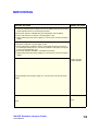
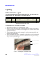
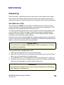
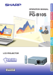
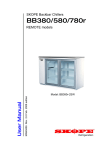
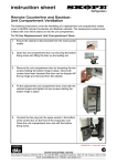
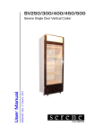
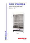
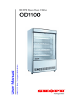
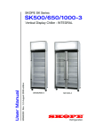
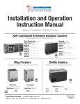
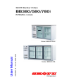
SKOPE Backbar Chillers
BB380/580/780i
INTEGRAL models
MAN0407 Rev. 3.0 Jan. 2008 edition
User Manual
Model: BB380i-2SW
Model: BB580i-3SL
SKOPE Backbar Integral Chiller
Models: BB380i-2/580i-3/780i-4
User Manual
MAN0407
Rev. 3.0 Jan. 2008 edition.
Copyright © 2007
SKOPE Industries Limited.
All rights reserved.
SKOPE Industries Limited reserve the right to alter
specifications without notice.
is a registered trade mark of
SKOPE Industries Limited.
TRADE MARK INFRINGEMENT
The SKOPE trade mark on this product is infringed if the owner, for the time
being, does any of the following:
•
Applies the trade mark to the product after their state, condition, get-up
or packaging has been altered in any manner
•
Alters, removes (including part removal) or obliterates (including part
obliteration) the trade mark on the product
•
•
Applies any other trade mark to the product
Adds to the product any written material that is likely to damage the
reputation of the trade mark
Notice of the above contractual obligations passes to:
•
Successors or assigns of the buyer
•
Future owners of the product
i
SKOPE Backbar Integral Chiller
User Manual
TABLE OF CONTENTS
INSTALLATION
Safety Information. . . . . . . . . . . . . . . . . . . . . . . . . . . . . . . . . . . . . . 4
Installing the Cabinet . . . . . . . . . . . . . . . . . . . . . . . . . . . . . . . . . . . 5
OPERATION
Cabinet Operation. . . . . . . . . . . . . . . . . . . . . . . . . . . . . . . . . . . . . . 7
ELECTRONIC CONTROLLER
Controller Display . . . . . . . . . . . . . . . . . . . . . . . . . . . . . . . . . . . . . . 8
Temperature Setpoint . . . . . . . . . . . . . . . . . . . . . . . . . . . . . . . . . . 10
SERVICING
Troubleshooting . . . . . . . . . . . . . . . . . . . . . . . . . . . . . . . . . . . . . . 11
Lighting . . . . . . . . . . . . . . . . . . . . . . . . . . . . . . . . . . . . . . . . . . . . . 14
Cleaning . . . . . . . . . . . . . . . . . . . . . . . . . . . . . . . . . . . . . . . . . . . . 15
Contact Addresses . . . . . . . . . . . . . . . . . . . . . . . . . . . . . . . . . . . . 17
Warranty . . . . . . . . . . . . . . . . . . . . . . . . . . . . . . . . . . . . . . . . . . . . 17
SKOPE Backbar Integral Chiller
User Manual
3
INSTALLATION
Safety Information
When using any electrical appliance, safety precautions should always be
observed. Read these instructions carefully and retain for future reference.
•
When used by, or near, young children or infirm persons, close supervision is
necessary. Young children should be supervised to ensure that they do not
play with the appliance.
•
Do NOT use this appliance for other than its intended use.
•
Do NOT cover the grilles or block the entry or exhaust of airflow by placing
objects up against the refrigeration unit.
•
Do NOT probe any opening.
•
Do NOT overload the power supply. See the rating label inside the cabinet for
power supply and current draw.
•
Only use this appliance with voltage specified on the rating label.
•
Ensure adequate ventilation of the SKOPE refrigeration unit.
•
Be careful not to touch moving parts and hot surfaces.
•
Regulations require that all electrical work be carried out by authorised
persons. For your own safety, and that of others, ensure this is done.
•
If the supply cord becomes damaged, it must be replaced by a SKOPE
authorised service agent, or similarly qualified person, in order to avoid a
hazard.
•
If the refrigeration unit is required to be installed or removed from the cabinet,
ensure all necessary safety precautions are observed.
•
This chiller is not designed to be stable in motion. Exercise caution when
moving or transporting this chiller.
Caution:
Disconnect the cabinet from the mains power supply before attempting
any cleaning or maintenance.
4
SKOPE Backbar Integral Chiller
User Manual
INSTALLATION
Installing the Cabinet
Castors / Legs
If your SKOPE Backbar Chiller has been supplied with either the optional adjustable
height castors or adjustable legs (packed with the cabinet), they should be fitted to
the base of the cabinet before final positioning of the chiller.
IMPORTANT: Do NOT lay the chiller onto its back when fitting the castors or legs.
Positioning
When positioning the chiller, avoid direct sunlight, and warm draughts etc.
Adequate allowance should be made for door opening. The chiller must be
positioned on a level surface for the doors to shut and seal correctly, and to prevent
the condensate tray from overflowing.
Ventilation
For efficient operation of the chiller, it is essential that adequate ventilation be
provided around the refrigeration unit. Maximum recommended operating ambient
temperature is 32°C at 65% RH, and for tropical machines is 40°C at 75% RH.
Important:
Never store cardboard cartons or other items in front of the
refrigeration unit. The ventilation slots in the unit front cover must be
kept clear at all times.
Shelves
Remove all packaging material from the shelves. Clip the shelf support brackets
into the shelf support strips, at the desired heights, and fit the shelves. The shelves
may be positioned at different heights to suit various products. Always ensure that
the shelf clips are securely engaged in each of the shelf support strips. The shelf
support strips are marked ‘+’ for easy location of shelf clips.
SKOPE Backbar Integral Chiller
User Manual
5
INSTALLATION
Power Supply
The chiller is supplied with a 2.3m flexible power cord fitted with a 3-pin plug, which
exits below the refrigeration unit front cover. Initial retrieval of the power cord is from
inside the refrigeration unit compartment, behind the unit front cover. To retrieve the
power cord:
1. Open the unit front cover, by undoing the bottom fixing screw and then lifting
the cover up from the bottom and swing open.
2. Pull the power cord fully out from the unit compartment and remove the rubber
band.
3. Push the unit end of the power cord into the grey plastic clip on the front of the
unit base and close the plastic clip over the cord, ensuring it is held firmly in
place (see Figure 1 below).
4. The power cord can now be run under the cabinet and plugged into a power
supply socket.
5. Close the unit front cover, by lifting the cover up from the bottom and pushing
firmly closed. Remember to refit the bottom fixing screw.
Condenser Coil
Unit Base
Unit Front Cover
Plastic Clip
Power Cord
Figure 1: Power Cord Clip
6
SKOPE Backbar Integral Chiller
User Manual
OPERATION
Cabinet Operation
Plug the chiller into the power supply and check operation of the refrigeration unit,
cabinet lighting and electronic controller.
Refrigeration Unit
The compressor and evaporator and condenser fans should all operate within two
minutes from the time the cabinet is plugged in. This may be verified by listening for
compressor switch on and checking for air movement out of the top ventilation slots
in the refrigeration unit front cover. The compressor and condenser fans should
switch off and on, depending on the cabinet temperature.
Cabinet Lighting
The light switch, located next to the electronic controller on the refrigeration unit
front cover, activates the cabinet interior lighting and can be switched on or off as
required. The fluorescent lights will require a period of time to stabilise following
initial start up.
Electronic Controller
At initial start up, the electronic controller will display the current cabinet
temperature (see pages 8-9 for controller display).
Loading Product
The chiller should be left running for 30 minutes before loading with product. When
loading the cabinet shelves with product:
•
Allow air space around all the product, to ensure even cooling and efficient
operation of the chiller. Leave airspace above product loaded on the top shelf
and leave a gap of approx. 50mm next to the return air grille between the
cabinet interior and the refrigeration unit compartment.
•
Do not allow products to overhang the front of the shelf as this could prevent
the doors from shutting or cause glass breakage. .
•
Do not exceed a maximum loading of 195 kg/m2.
•
Remove some product if the shelves are flexing or bending.
SKOPE Backbar Integral Chiller
User Manual
7
ELECTRONIC CONTROLLER
Controller Display
Figure 2: Controller Display
Keypad
ITEM
KEY
FUNCTION
1
Prg / mute: To initiate programme sets, press for 5 seconds. Mutes
the audible alarm (buzzer) and deactivates the alarm relay.
2
UP / aux: To scroll settings UP (in programme mode).
3
Set: If pressed for more than 2 seconds displays and / or enables
changing the temperature setpoint (see page 10).
4
DOWN / def: To scroll settings DOWN (in programme mode).
Table 1: Keypad Functions
8
SKOPE Backbar Integral Chiller
User Manual
ELECTRONIC CONTROLLER
Icons
ITEM
ICON
FUNCTION
5
COMPRESSOR:
ON when the compressor and condenser fan starts. Flashes when
activation of the compressor is temporarily delayed.
6
FAN: n.a.
7
DEFROST:
ON when the defrost is activated. Flashes when the activation of
the defrost is temporarily delayed due to procedures in progress.
8
AUX: n.a.
9
ALARM: Flashes in the event of alarms.
10
CLOCK: n.a.
11
LIGHT: n.a.
12
SERVICE: Flashes in the event of malfunctions.
13
DISPLAY: Shows the cabinet temperature.
14
HACCP: n.a.
15
CONTINUOUS CYCLE: n.a.
Table 2: Icon Functions
SKOPE Backbar Integral Chiller
User Manual
9
ELECTRONIC CONTROLLER
Temperature Setpoint
The chiller temperature setpoint is factory set at 1.0°C. If necessary the standard
setting can be adjusted between 0.5°C and 3.5°C (see Table 3 below).
SKOPE do not recommend that the setpoint be changed unless it is absolutely
necessary, and then only by small increments at a time.
To View and Adjust the Temperature Setpoint:
1. To view the setpoint: press and hold the SET
key for 2 seconds, until the setpoint value
flashes.
2. To adjust the setpoint: press either the UP or
DOWN keys to display the required setpoint
value.
3. Press the SET key again to memorise the
new setpoint value. If this is not done within
60 seconds, changes will be lost and you will
need to repeat the above procedure.
Table 3: Viewing and Adjusting the Temperature Setpoint
10
SKOPE Backbar Integral Chiller
User Manual
SERVICING
Troubleshooting
Complaint
Possible Cause
Repair
1. Cabinet not
operating and no
controller display:
• Loss of power supply.
• Check mains power supply.
2. Cabinet lights not
operating:
• Blown cabinet fuse.
• Requires technical repair by a
SKOPE Authorised Service Agent.
• Failed fluorescent tube.
• Check fluorescent tubes.
• Controller alarm.
• Determine cause and eliminate (see
pages 12-13).
3. Power
consumption is
higher than
expected:
• Unit operating too hot.
• Clean condenser. Ensure the chiller
is installed with good ventilation
around the refrigeration unit.
• Cabinet door is opened excessively.
• Keep door/s open for minimum time.
4. Product is too
warm and
spoiling:
• Restricted cabinet airflow.
• Ensure product is not blocking
airflow slots and there is air space
around all the product.
• Temperature setpoint is too warm.
• Adjust setpoint (see page 10).
5. Warm cabinet
• Blocked condenser.
temperatures and/ • Poor refrigeration unit ventilation.
or compressor
operating for long
periods (more
than 1 hour):
• Clean condenser (see page 15).
• Ensure the cabinet is installed with
good ventilation around the
refrigeration unit.
Table 4: Troubleshooting
SKOPE Backbar Integral Chiller
User Manual
11
SERVICING
Controller Alarms
CODE
DISPLAY ICON
ALARM DESCRIPTION
Flashing
Product HIGH temperature alarm
Flashing
Product LOW temperature alarm
Flashing
Refrigeration system high temperature
pre-warning
Flashing
Refrigeration system high temperature
shutdown
Flashing
Ambient probe fault
Flashing
Evaporator probe fault
Flashing
Condenser probe fault
None
Defrost over-time limit
Flashing
Real-time clock fault
Flashing
Controller E prom error
Flashing
Controller E prom error
None
Start defrost request
None
End defrost request
Table 5: Controller Alarms
12
SKOPE Backbar Integral Chiller
User Manual
SERVICING
INITIAL ACTION
FINAL ACTION
1. Check the cabinet product loading to ensure ventilation slots are not blocked
and that product does not overhang the shelves.
2. Ensure the cabinet is installed with good refrigeration unit ventilation.
3. Check and clean the condenser coil (see pages 15-16).
4. Unplug cabinet from the power supply for 1 minute, then reconnect to power
supply.
1. Clean the condenser coil (see pages 15-16).
2. Check refrigeration ventilation. Ensure clear airpath at the top and front of
the cabinet (to extract hot air). A minimum of 200mm clear space is required
in front of the refrigeration unit.
3. Ensure the cabinet is installed in a suitable environment.
4. Unplug cabinet from the power supply for 1 minute, then reconnect to power
supply.
If alarm persists,
contact SKOPE.
Unplug cabinet from the power supply for 1 minute, then reconnect to power
supply.
None
SKOPE Backbar Integral Chiller
User Manual
None
13
SERVICING
Lighting
Cabinet Interior Lights
The chiller is fitted with a full length horizontal interior light. The light houses one
fluorescent tube. See Table 6 below for the correct tube size.
Model
Doors
Fluorescent Tube
Qty
BB380i-2
2 Door
30 Watt T8 fluorescent tube (Ø26mm x 915mm)
1
BB580i-3
3 Door
36 Watt T8 fluorescent tube (Ø26mm x 1219mm)
1
BB780i-4
4 Door
58 Watt T8 fluorescent tube (Ø26mm x 1524mm)
1
Table 6: Fluorescent Tube Sizes
To Replace the Fluorescent Tube:
1. Disconnect the cabinet from the mains power supply.
2. Remove the top light diffuser, by compressing the back section of the diffuser
until it disengages from the aluminium housing and then push the diffuser back
(see Figure 3 below).
3. The fluorescent tube can now be removed by revolving the tube until the pin
position allows withdrawal.
4. When refitting the light diffuser, engage the back section into the housing, and
then compress and snap the front section of diffuser back into place working
along the full length of the light.
Fluorescent Tube
Top Light Diffuser
Figure 3: Replacing the Fluorescent Tube
14
SKOPE Backbar Integral Chiller
User Manual
SERVICING
Cleaning
When necessary, wipe both the interior and exterior of the cabinet with a damp
cloth. Ensure the cabinet is disconnected from the mains power supply before
cleaning the cabinet. Periodic cleaning of the condenser coil is also recommended.
Condenser Coil
The condenser coil MUST be kept clean for reliable operation and to minimise
power consumption (a blocked condenser can double power consumption). The
condenser coil is situated behind the unit front cover.
To ensure trouble free performance, the condenser coil should be brushed clean
once a month (see Figure 4 on page 16) and blown clean by qualified service
personnel every six months. If the electronic controller display flashes ‘cht’ the
condenser coil immediately needs cleaning.
Over time, dust may accumulate within the condenser that cannot be removed with
a brush. if this occurs, contact SKOPE to arrange for a SKOPE Authorised Service
Agent to clean the condenser with compressed air.
Important:
If the electronic controller display flashes ‘cht’ the condenser coil must
be cleaned immediately.
To access the condenser coil:
1. Disconnect the cabinet from the mains power supply.
2. Open the unit front cover, by undoing the bottom fixing screw and then lifting
the cover up from the bottom and swing open.
3. The condenser coil is now accessible for cleaning (see Figure 4 on page 16).
4. Close the unit front cover, by lifting the cover up from the bottom and pushing
firmly closed. Remember to refit the bottom fixing screw.
Caution:
Disconnect the cabinet from the mains power supply before attempting
any cleaning or maintenance.
SKOPE Backbar Integral Chiller
User Manual
15
SERVICING
Condenser Coil
Figure 4: Cleaning the Condenser Coil
16
SKOPE Backbar Integral Chiller
User Manual
SERVICING
Contact Addresses
New Zealand
SKOPE INDUSTRIES LIMITED
Head Office
PO Box 1091, Christchurch
New Zealand
Freephone: 0800 947 5673
Fax: (03) 983 3896
E-mail: [email protected]
Website: www.skope.co.nz
Australia
SKOPE AUSTRALIA PTY LTD
A.C.N. 000 384 270
PO Box 7543, Baulkham Hills B.C.
NSW 2153, Australia
Freephone: 1800 121 535
Fax: 1800 121 533
E-mail: [email protected]
Website: www.skope.com.au
Warranty
To receive a warranty for your purchased cabinet, you MUST register your cabinet
within four weeks from the date of invoice either by:
•
filling out the in-cabinet warranty form and posting or faxing it back to SKOPE
•
or filling out the online warranty form.
Cabinets that are not registered within the four weeks are not eligible for a warranty.
SKOPE Backbar Integral Chiller
User Manual
17