1
Model
M
d lN
No.
TH-60PF50U
TH-65PF50U
Operating Instructions
Network Operations
High Denition Plasma Display
English
Before connecting, operating or adjusting this product,
please read these instructions completely.
Please keep this manual for future reference.
Contents
Request Regarding Security · · · · · · · · · · · · · · · · · · · · · · · · · · · · · · · · · · · · · · · · · · · · ·3
What you can do · · · · · · · · · · · · · · · · · · · · · · · · · · · · · · · · · · · · · · · · · · · · · · · · · · · · · · ·4
Notes on Using Wireless Connection · · · · · · · · · · · · · · · · · · · · · · · · · · · · · · · · · · · · · ·5
Check your computer · · · · · · · · · · · · · · · · · · · · · · · · · · · · · · · · · · · · · · · · · · · · · · · · · · ·7
Necessary environment for computers to be connected· · · · · · · · · · · · · · · · · · · · · · · · · · · · · · · · 7
Connection · · · · · · · · · · · · · · · · · · · · · · · · · · · · · · · · · · · · · · · · · · · · · · · · · · · · · · · · · · · ·8
Example of Network Connection (Wired LAN) · · · · · · · · · · · · · · · · · · · · · · · · · · · · · · · · · · · · · · · · 8
Connecting Wireless Module (Wireless LAN) · · · · · · · · · · · · · · · · · · · · · · · · · · · · · · · · · · · · · · · · · 8
Network Setup · · · · · · · · · · · · · · · · · · · · · · · · · · · · · · · · · · · · · · · · · · · · · · · · · · · · · · · · ·9
Displaying the NETWORK SETUP menu · · · · · · · · · · · · · · · · · · · · · · · · · · · · · · · · · · · · · · · · · · · · · 9
WIRED LAN · · · · · · · · · · · · · · · · · · · · · · · · · · · · · · · · · · · · · · · · · · · · · · · · · · · · · · · · · · · · · · · · · · · · ·10
WIRELESS LAN · · · · · · · · · · · · · · · · · · · · · · · · · · · · · · · · · · · · · · · · · · · · · · · · · · · · · · · · · · · · · · · · ·11
NAME CHANGE· · · · · · · · · · · · · · · · · · · · · · · · · · · · · · · · · · · · · · · · · · · · · · · · · · · · · · · · · · · · · · · · · ·14
PASSWORD · · · · · · · · · · · · · · · · · · · · · · · · · · · · · · · · · · · · · · · · · · · · · · · · · · · · · · · · · · · · · · · · · · · · ·15
COMPUTER SEARCH · · · · · · · · · · · · · · · · · · · · · · · · · · · · · · · · · · · · · · · · · · · · · · · · · · · · · · · · · · · · ·16
MULTI-LIVE · · · · · · · · · · · · · · · · · · · · · · · · · · · · · · · · · · · · · · · · · · · · · · · · · · · · · · · · · · · · · · · · · · · · ·16
LIVE MODE CUT IN · · · · · · · · · · · · · · · · · · · · · · · · · · · · · · · · · · · · · · · · · · · · · · · · · · · · · · · · · · · · · · ·16
CONTROL I/F SELECT · · · · · · · · · · · · · · · · · · · · · · · · · · · · · · · · · · · · · · · · · · · · · · · · · · · · · · · · · · · ·17
WEB CONTROL · · · · · · · · · · · · · · · · · · · · · · · · · · · · · · · · · · · · · · · · · · · · · · · · · · · · · · · · · · · · · · · · · ·17
STATUS · · · · · · · · · · · · · · · · · · · · · · · · · · · · · · · · · · · · · · · · · · · · · · · · · · · · · · · · · · · · · · · · · · · · · · · ·17
RESET · · · · · · · · · · · · · · · · · · · · · · · · · · · · · · · · · · · · · · · · · · · · · · · · · · · · · · · · · · · · · · · · · · · · · · · · ·17
Connecting with Wired LAN · · · · · · · · · · · · · · · · · · · · · · · · · · · · · · · · · · · · · · · · · · · · · 18
Computer operation · · · · · · · · · · · · · · · · · · · · · · · · · · · · · · · · · · · · · · · · · · · · · · · · · · · · · · · · · · · · · ·18
Connecting with Wireless LAN · · · · · · · · · · · · · · · · · · · · · · · · · · · · · · · · · · · · · · · · · · 18
Computer operation · · · · · · · · · · · · · · · · · · · · · · · · · · · · · · · · · · · · · · · · · · · · · · · · · · · · · · · · · · · · · ·18
Using Web Browser·
r · · · · · · · · · · · · · · · · · · · · · · · · · · · · · · · · · · · · · · · · · · · · · · · · · · · 19
Accessing from the Web browser·
r · · · · · · · · · · · · · · · · · · · · · · · · · · · · · · · · · · · · · · · · · · · · · · · · · ·19
PJLink™ Protocol · · · · · · · · · · · · · · · · · · · · · · · · · · · · · · · · · · · · · · · · · · · · · · · · · · · · ·27
Trademarks · · · · · · · · · · · · · · · · · · · · · · · · · · · · · · · · · · · · · · · · · · · · · · · · · · · · · · · · · ·28
2
Request Regarding Security
When using this product, security breaches of the type described below are conceivable.
• Leakage of your private information via this product
• Illegal operation of this product by a malicious third-party
• Harm to or cessation of operation of this product by a malicious third-party
Be sure to implement sufcient security measures.
•
•
•
•
Set passwords, and limit the users that are permitted login access.
Make sure the password is as hard to guess as possible.
Change the password periodically.
Panasonic Corporation and its afliated companies never directly ask customers for their password. Do not give
out your password even if directly asked by a third-party representing themselves as Panasonic Corporation.
• Always use on a network that has safety protection such as a rewall implemented.
About Wireless LANs
The advantage of a wireless LAN is that information can be exchanged between a PC or other such equipment and an
access point using radio waves as long as you are within range for radio transmissions.
On the other hand, because the radio waves can travel through obstacles (such as walls) and are available everywhere
within a given range, problems of the type listed below may occur if security-related settings are not made.
• A malicious third-part may intentionally intercept and monitor transmitted data including the content of e-mail and
personal information such as your ID, password, and/or credit card numbers.
• A malicious third-party may access your personal or corporate network without authorization and engage in the
following types of behavior.
Retrieve personal and/or secret information (information leak)
Spread false information by impersonating a particular person (spoofing)
Overwrite intercepted communications and issue false data (tampering)
Spread harmful software such as a computer virus and crash your data and/or system (system crash)
Since most wireless LAN adapters or access points are equipped with security features to take care of these problems,
you can reduce the possibility of these problems occurring when using this product by making the appropriate security
settings for the wireless LAN device.
Some wireless LAN devices may not be set for security immediately after purchase. To decrease the possibility of
occurrence of security problems, before using any wireless LAN devices, be absolutely sure to make all security-related
settings according to the instructions given in the operation manuals supplied with them.
Depending on the specifications of the wireless LAN, a malicious third-party may be able to break security settings by
special means.
Please contact Panasonic if you need help taking care of security settings or other such.
If you cannot perform security settings for your wireless LAN by yourself, please contact the Panasonic Support Center.
Panasonic asks customers to thoroughly understand the risk of using this product without making security settings, and
recommends that the customer make security settings at their own discretion and responsibility.
3
What you can do
This unit supports wired LAN and wireless LAN enabling the network functions as below.
<WEB control> (See page 19)
The following operations are possible when using WebBrowser.
• Setting and adjusting the Display
• Displaying the Display status
<PJLink> (See page 27)
Compatible with PJLink Class 1. The following operations can be performed from a computer when PJLink protocol
is used.
• Setting the Display
• Querying the Display status
<Command control>
Network function of the unit can control the unit in the same way as serial control from a network.
Supported commands
Commands used in the serial control are supported. (See page 15 of “Operating Instructions, Display Operations”)
When using [WEB control], [PJLink] and [Command control], set [CONTROL I/F SELECT] to [LAN] and [WEB
CONTROL] to [ON] in the [NETWORK SETUP] menu. (See page 17)
Manager mobile edition 5.5 (Windows/Macintosh)
Wireless
Software for sending the computer screen via wireless/wired LAN.
To use this function, the software included in the wireless module (ET-WM200U) (sold separately) is necessary.
For more information, see the instructions of the software contained in the CD-ROM supplied with the wireless
module.
This unit does not support the following functions.
Virtual remote control function
USB display function
Projector for iOS
Wireless
Software for sending PDF les/JPEG images saved in an iPad/iPhone/iPod touch to this unit via wireless LAN
(WiFi).
For more information, see the website below.
http://panasonic.net/avc/projector/ios/
4
Notes on Using Wireless Connection
Wireless connection function of the Display uses radio waves in the 2.4 GHz band.
A radio station license is not required, but be sure to read and fully understand the following items before use.
The wireless module (part number: ET-WM200U) sold separately needs to be mounted when using the wireless LAN function
with the Display.
Do not use near other wireless equipment.
The following equipment may use radio waves in the same band as the Display.
When the Display is used near these devices, radio wave interference may make communication impossible, or the
communication speed may become slower.
• Microwave ovens, etc.
• Industrial, chemical and medical equipment, etc.
• In-plant radio stations for identifying moving objects such as those used in factory manufacturing lines, etc.
• Designated low-power radio stations
If at all possible, avoid the use of cellular phones, TV sets or radios near the Display.
Cellular phones, TV sets, radios and similar devices use different radio bands from the Display, so there is no effect on
wireless communication or the transmission and reception of these devices. However, radio waves from the Display may
produce audio or video noise.
Wireless communication radio waves cannot penetrate steel reinforcements, metal, concrete,
etc.
Communication is possible through walls and floors made from materials such as wood and glass (except glass containing
wire mesh), but not through walls and floors made from steel reinforcements, metal, concrete, etc.
Avoid using the Display in locations prone to static electricity.
If the Display is used in a location prone to static electricity, such as on a carpet, the wireless LAN or wired LAN connection
may be lost.
If this happens, eliminate the source of static electricity or electromagnetic noise and reconnect to the wireless LAN or
wired LAN.
Using the Display outside the country
It is forbidden to take the Display outside the country or region where you purchased it, so use it only in the said country or
region. Also, note that depending on countries or regions there are restrictions on the channels and frequencies at which
you can use the wireless LAN.
5
Notes on Using Wireless Connection
Wired LAN
Use straight or crossover LAN cable that is compatible with category 5 or above.
¼ Whether straight cable, crossover cable or both can be used varies depending on the system configuration. For details,
consult your system administrator.
Available wireless LAN channels
The channels (frequency range) that can be used differ according to the country or region. Refer to the table below.
Country or region
Standard
United States
FCC part 15
Channels used
1 – 11
Canada
RSS
Frequency band
(Center frequency)
2.412 MHz 2.462 MHz
The separately sold wireless module (product number: ET-WM200U) needs to be attached to use wireless LAN
with this device (See page 8).
6
Check your computer
Necessary environment for computers to be connected
• First, check your computer to see whether or not it has a wired LAN or a built-in wireless LAN function.
• Before connecting the Display to the computer, be sure to check the following settings.
• Operation is not guaranteed for all wireless LAN adapters and built-in wireless LAN adapters.
Wired LAN
Check 1
For LAN cable
• Is the cable properly connected?
• Use LAN cable that is compatible with category 5 or above.
Check 2
Wired LAN settings
<Computer with a built-in wired LAN function>
• Is your wired LAN switched on?
<Computer without a built-in wired LAN function>
• Is your wired LAN adapter properly recognized?
• Is your wired LAN adapter switched on?
• Install the wired LAN adapter driver beforehand.
For details on how to install the driver, refer to the instructions accompanying the wired LAN adapter.
Wireless LAN
Check 1
Wireless LAN settings
<Computer with a built-in wireless LAN function>
• Is your wireless LAN switched on?
<Computer without a built-in wireless LAN function>
• Is your wireless LAN adapter properly recognized?
• Is the wireless LAN adapter switched on?
• Install the wireless LAN adapter driver beforehand.
For details on how to install the driver, refer to the instructions accompanying the wireless card.
Check 2
Computer’s settings
• When security (rewall) software and utilities for network cards are installed, these may prevent connection of
the Display.
<Windows XP/Windows Vista/Windows 7>
• Is Network Bridge enabled?
• Has your rewall been disabled?
For WebBrowser
• WebBrowser is necessary to use WEB control.
• Compatible OS : Windows XP/Windows Vista/Windows 7, Mac OS X v10.4/v10.5/v10.6/v10.7
• Compatible WebBrowser : Internet Explorer 7.0/8.0/9.0, Safari 4.0/5.0 (Mac OS)
7
Connection
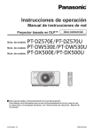
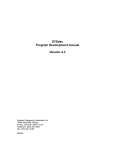
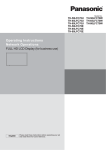
Example of Network Connection (Wired LAN)
COMPUTER
Display (main unit, rear)
Less
than
3.9 inch
(10 cm)
LAN cable
(not supplied)
Ferrite core
(supplied)
Installing the Ferrite core
Ferrite core
(supplied)
Less
than
3.9 inch (10 cm)
Open
Pull back the tabs
(in two places)
Wind the cable
twice
Press the cable
through and close
Hub or broadband router
• Make sure the broadband router or hub supports 10BASE-T/100BASE-TX.
• To connect a device using 100BASE-TX, use “category 5” LAN cable.
• Touching the LAN terminal with a statically charged hand (body) may cause damage due to its discharge.
Do not touch the LAN terminal or a metal part of the LAN cable.
• For instructions on how to connect, consult your network administrator.
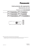
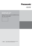
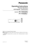
Connecting Wireless Module (Wireless LAN)
To use the wireless function, the wireless module (ET-WM200U) (sold separately) is necessary.
When connecting the wireless module to the
display, remove the protective lm and cap.
Connecting procedure
Hold the wireless module with its LED on the near
side and connect it to the wireless module connection
terminal.
(8Ω,20W[10W+10W])
Do not connect any other device than the wireless module
(ET-WM200U).
ET-WM200
LED
8
Network Setup
Make the various settings to use the network function.
For network settings, contact your network administrator.
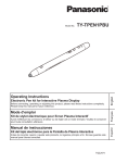
Displaying the NETWORK SETUP menu
1
Press
to display [SETUP] menu.
SETUP
2/2
MULTI DISPLAY SETUP
PORTRAIT SETUP
ON/OFF TIMER SET UP
DAY/TIME SETUP
NETWORK SETUP
DISPLAY ORIENTATION LANDSCAPE
2
[Starting up the network]
It takes some time for the network to start up just after the
Display power is turned on.
During that time, “NETWORK SETUP” in the “SETUP”
menu is grayed out and cannot be set.
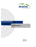
Select [NETWORK SETUP] with the and press
button.
The [NETWORK SETUP] menu appears.
NETWORK SETUP
WIRED LAN
WIRELESS LAN
NAME CHANGE
PASSWORD
COMPUTER SEARCH
MULTI-LIVE
LIVE MODE CUT IN
CONTROL I/F SELECT
WEB CONTROL
STATUS
RESET
3
OFF
RS-232C
ON
Press to select the item and set with .
Press
to display sub menu.
9
Network Setup
WIRED LAN
You can make detailed wired LAN settings.
1
Select [WIRED LAN] in [NETWORK SETUP] menu and press
Address settings
1 Select the item and press
WIRED LAN
SAVE
DHCP
IP ADDRESS
SUBNET MASK
GATEWAY
IP ADDRESS
192.168.
I
OFF
192.168. 10.100
255.255.255. 0
192.168. 0. 1
2
3
4
.
8
Use to select a digit.
Use to change a number.
Press .
Pressing
2
0.
button.
will cancel the address change.
Set [DHCP].
When [OFF] is selected, IP ADDRESS and other settings can be set manually.
ON:
DHCP
If a DHCP server exists in the network to which the display
is connected, the IP address will automatically be acquired.
OFF: If a DHCP server does not exist in the network to which
the display is connected, additionally set [IP ADDRESS],
[SUBNET MASK] and [GATEWAY].
(DHCP client function)
IP ADDRESS
Enter the IP address if DHCP server is not used.
(Display of IP address and setting)
SUBNET MASK
(Displaying and setting the subnet mask)
GATEWAY
(Display of gateway address and setting)
If not using a DHCP server, enter the subnet mask.
Enter the gateway address if DHCP server is not used.
If [DHCP] is set to [ON], the IP address and other items are not displayed. Check the [STATUS] page for the
current IP address and other items. (See page 17)
3
Select [SAVE] and press
button.
Save the current network settings.
If message indicating a duplicate IP address is displayed in [STATUS] (see page 17), check the same IP
address is not used within the same network.
• Before using the DHCP server, make sure the DHCP server is already functioning.
• For details of IP address, subnet mask, and gateway, ask the network administrator.
• A wired LAN and wireless LAN cannot be used in the same segment.
Default wired LAN settings
The following settings are set before the Display leaves the factory.
DHCP
IP ADDRESS
SUBNET MASK
GATEWAY
10
OFF
192.168.10.100
255.255.255.0
192.168.10.1
Network Setup
WIRELESS LAN
You can make detailed wireless LAN settings.
You can congure settings when the wireless module (ET-WM200U) is mounted.
Setting network number
1
Select [WIRELESS LAN] in [NETWORK SETUP] menu and press
2
Select the number to be connected for
[WIRELESS LAN].
• [OFF], [S-MAP], [1]-[4], [USER1]-[USER3]
button.
WIRELESS LAN
SAVE
WIRELESS LAN
OFF
• Selecting [OFF] disables the wireless LAN.
• Network number: [S-MAP] and [1]-[4] are available only when connecting via wireless LAN with the application
software the “Wireless Manager mobile edition 5.5”. [S-MAP] is for showing connectable displays on the network
according to their levels of radio wave intensity. For details, refer to the operation manual of the “Wireless
Manager mobile edition 5.5”.
USER settings
You can congure more precise network settings, if you select from [USER1] to [USER3] (user) for [WIRELESS LAN].
1
Select [USER1] – [USER3] for [WIRELESS LAN].
Address settings
1 Select the item and press
WIRELESS LAN
SAVE
WIRELESS LAN
NAME CHANGE
DHCP
IP ADDRESS
SUBNET MASK
GATEWAY
OFF
192.168. 10. 100
255.255.255. 0
192.168. 0. 1
SSID
MODE
2
IP ADDRESS
192.168.
I
USER1
2
3
4
0.
.
8
Use to select a digit.
Use to change a number.
Press .
Pressing
will cancel the address change.
AD HOC
Set [DHCP].
When "OFF" is selected, IP ADDRESS and other settings can be set manually.
NAME CHANGE
DHCP
(DHCP client function)
IP ADDRESS
(Display of IP address and setting)
You can change the user name. Entering characters
page 14
ON: If a DHCP server exists in the network to which the display is
connected, the IP address will automatically be acquired.
OFF: If a DHCP server does not exist in the network to which
the display is connected, additionally set [IP ADDRESS],
[SUBNET MASK] and [DEFAULT GATEWAY].
Enter the IP address if DHCP server is not used.
SUBNET MASK
(Displaying and setting the subnet If not using a DHCP server, enter the subnet mask.
mask)
GATEWAY
(Display of gateway address and
setting)
Enter the gateway address if DHCP server is not used.
• If [DHCP] is set to [ON], the IP address and other items are not displayed. Check the [STATUS] page for the
current IP address and other items. (See page 17)
• Before using the DHCP server, make sure the DHCP server is already functioning.
• For details of IP address, subnet mask, and gateway, ask the network administrator.
• A wired LAN and wireless LAN cannot be used in the same segment.
11
Network Setup
3
Press to go to the next item.
Make the settings related to the wireless connection between the Display and the network.
SSID
MODE
AUTHENTICATION
ENCRYPTION
CHANNEL
AD HOC
OPEN
NONE
10
: If the mode is [AD HOC], enter the same character string as that of SSID
set on the computer to be connected. If the mode is
[INFRASTRUCTURE], enter the SSID registered at the access point.
Entering characters
page 14
• SSID has to be entered in alphanumeric letters.
• You cannot set “any” or “ANY” for SSID.
MODE
AD HOC
: Connect Display and computer directly without access point.
INFRASTRUCTURE
: Connect through access point.
AUTHENTICATION
OPEN
SHARED
: Set the user authentication method used by the network to be connected.
: Select when making a connection using [AD HOC], or when the access
point authentication method is OpenSystem.
: Select when making a connection using [AD HOC], or when the access
point authentication method is Shared Key.
WPA-PSK ¼
WPA2-PSK ¼
WPA-EAP/
WPA2-EAP ¼
WPA-EAP ¼
WPA2-EAP ¼
¼ : Available when the mode is set to [INFRASTRUCTURE].
ENCRYPTION
NONE
WEP
TKIP
AES
CHANNEL
: Select the encryption method to be used for communication between the
Display and the network.
: Select when transmit without encryption. It is selectable only when
[AUTHENTICATION] is [OPEN] or [SHARED].
: Select when ENCRYPTION is WEP.
: Select when ENCRYPTION is TKIP.
Selectable when [AUTHENTICATION] is either [WPA-PSK], [WPA2-PSK],
[WPA-EAP], [WPA2-EAP].
: Select when ENCRYPTION is AES.
Selectable when [AUTHENTICATION] is either [WPA-PSK], [WPA2-PSK],
[WPA-EAP], [WPA2-EAP].
: Refer to page 6 for usable channels.
Important video/audio data is protected because AES encryption programming takes place in advance for
all network numbers, even if [ENCRYPTION] is set to [NONE].
12
Network Setup
4
Press to go to the next item.
In addition, further perform the following setting depending on [AUTHENTICATION] and [ENCRYPTION]
settings.
DEFAULT KEY
KEY 1
KEY 2
KEY 3
KEY 4
1
********
********
********
********
setting [OPEN] or [SHARED] as authentication and setting [WEP] as the
When
encryption method:
DEFAULT KEY
KEY1 – 4
: Set 1 – 4 numerals for the default key.
: Set a WEP key to the key number selected with [DEFAULT KEY].
Either the 64-bit or 128-bit WEP key can be set. For the 64-bit key, input ve
alphanumerics (or a 10-digit string for the hexadecimal format) for the 128-bit key, input
13 alphanumerics (or a 26-digit string for the hexadecimal format).
When using [WPA-PSK] or [WPA2-PSK] :
Set a key.
Input either 8 to 63 alphanumerics or a 64 digit string in the hexadecimal format.
When the authentication method is [WPA-EAP/WPA2-EAP], [WPA-EAP], [WPA2-EAP]:
Set [EAP], [USER NAME], and [PASSWORD].
EAP:
Select the EAP setup in the RADIUS server. Types of EAP that can be selected are as
follows.
PEAP (MS-CHAPv2), PEAP (GTC), EAP-TTLS (MD5),
EAP-TTLS (MS-CHAPv2), EAP-FAST(MS-CHAPv2), EAP-FAST(GTC), EAP-TLS ¼
USER NAME: Input a user name used for authentication (excluding spaces)(maximum 64 characters).
PASSWORD: Input a password used for authentication (maximum 64 characters).
¼ : When [EAP-TLS] is selected as EAP, it is required to setup “USER NAME”, “PASSWORD”, “DIGITAL
CERTIFICATE”, and “CA CERTIFICATE” with the WEB browser. (See page 24 – 25)
• If you are unable to connect to the wireless LAN through the access point, contact the manufacturer of
the access point.
• When using EAP, the display needs to be set according to the setting of the RADIUS server. Check with
the network administrator for the setting of the RADIUS server.
• When using an EAP together with an access point with invalid SSID broadcast, select WAP-EAP or
WAP2-EAP for the authentication method even if the authentication method of the access point is WPAEAP/WPA2-EAP.
5
Select [SAVE] and press
button.
Save the current network settings.
Default wireless LAN settings
The following settings are set before the Display leaves the factory.
SSID
DHCP
IP ADDRESS
SUBNET MASK
GATEWAY
Panasonic Display
OFF
192.168.11.100
255.255.255.0
192.168.11.1
MODE
AUTHENTICATION
ENCRYPTION
CHANNEL
AD HOC
OPEN
NONE
11
13
Network Setup
NAME CHANGE
You can change the Display name to be displayed on the network.
1
Select [NAME CHANGE] in [NETWORK SETUP] menu and press
button.
The keyboard is displayed.
Up to 8 characters can be entered for the Display name.
NAME CHANGE
Name0000
A B C
N O P
a b c
n o p
0 1 2
!
” #
_ `
|
D
Q
d
q
3
$
~
E
R
e
r
4
%
<
F
S
f
s
5
&
>
OK
G
T
g
t
6
’
(
H
U
h
u
7
)
I
V
i
v
8
+
[
J
W
j
w
9
–
]
K
X
k
x
L M ALL DELETE
Y Z
DELETE
l m
y z
SPACE
/ = ? @ \
ˆ
{
}
,
.
;
:
CANCEL
1 select
2 set
[Entering characters]
To enter text, select characters in the on-screen keyboard.
Example: Specifying “PDP 01”
1 Select “ALL DELETE”.
Name0000
All text is deleted.
To delete individual characters, select “DELETE”.
2 Select “P”.
P
Repeat this process to enter the next character.
3 Select “D” and “P”.
PDP
4
Select “SPACE”.
PDP
5
Select “0” and “1”.
PDP 01
2
14
When you nished entering the Display name, select [OK] and press
To cancel saving the Display name, select [CANCEL].
.
Network Setup
PASSWORD
Set to [ON] to perform password check when connecting with the Display using “Wireless Manager mobile edition
5.5”.
By controlling connection with password setting, it is possible to prevent an external device from accidentally
connecting and interrupting images, etc.
1
Select [PASSWORD] in [NETWORK SETUP] menu and press
button.
PASSWORD
PASSWORD
PASSWORD CHANGE
2
OFF
Select [ON] or [OFF] for [PASSWORD].
PASSWORD CHANGE
Password can be registered or changed. No password is set in the default setting.
1
Select [PASSWORD CHANGE] and press
button.
The keyboard is displayed.
Up to 8 characters can be entered for the password.
page 14
Entering characters
2
When you nished entering the password, select [OK] and press
.
To cancel saving the password, select [CANCEL].
It is recommended to change password on a regular basis for keeping it private.
15
Network Setup
COMPUTER SEARCH
You can search computers that can connect using the “Wireless Manager mobile edition 5.5”. See the “Wireless
Manager mobile edition 5.5” operation manual for details.
* You can congure settings when the wireless module (ET-WM200U) is mounted.
1
Select [COMPUTER SEARCH] in [NETWORK SETUP] menu and press
button.
The list of connectable computers on the network is displayed.
COMPUTER SEARCH
1.
Name001
2.
Name002
SEARCH COMPLETE.
2
Select the computer to be connected and press
.
MULTI-LIVE
Switch to the MULTI-LIVE mode when using the “Wireless Manager mobile edition 5.5”. See the “Wireless
Manager mobile edition 5.5” operation manual for details.
Select [MULTI-LIVE] in [NETWORK SETUP] menu and press
button.
LIVE MODE CUT IN
Set this [ON] to allow interrupt of the Live mode by other users while the Live mode is active (sending image) by
the “Wireless Manager mobile edition 5.5”. For details, refer to “Wireless Manager mobile edition 5.5” operating
manual.
1
2
16
Select [LIVE MODE CUT IN] in [NETWORK SETUP] menu and press
Select [ON] or [OFF].
button.
Network Setup
CONTROL I/F SELECT
Set whether to control with RS-232C (serial) or LAN. When [LAN] is set, the slot power is turned on, and power
indicator is lit orange under the condition of power off with remote control (stand-by state), regardless of the [Slot
power] setting.
1
Select [CONTROL I/F SELECT] in [NETWORK SETUP] menu and press
2
Select [RS-232C] or [LAN].
button.
WEB CONTROL
Select [ON] to control the display from the web browser. When [ON] is set, the slot power is turned on, and power
indicator is lit orange under the condition of power off with remote control (stand-by state), regardless of the [Slot
power] setting.
1
Select [WEB CONTROL] in [NETWORK SETUP] menu and press
2
Select [ON] or [OFF].
button.
STATUS
Displays the current network status.
Select [STATUS] in [NETWORK SETUP] menu and press
button.
The Display information, settings of wired LAN and wireless LAN are displayed.
RESET
You can reset the network setting to the factory default of the Display.
1
Select [RESET] in [NETWORK SETUP] menu and press
button.
NETWORK SETUP
RESET
OK
2
CANCEL
Select [OK] and press
.
It takes some time to restart network while the network settings are initialized.
During that time, “NETWORK SETUP” in the “SETUP” menu is grayed out and cannot be set.
17
Connecting with Wired LAN
To use the network function, make the necessary settings in [NETWORK SETUP] and be sure to set [CONTROL
I/F SELECT] to [LAN]. (See page 9)
When [LAN] is set, the slot power is turned on, and power indicator is lit orange under the condition of power off
with remote control (stand-by state), regardless of the [Slot power] setting.
Computer operation
Connection can be made with wired LAN. However, conrm to your system administrator on network settings
before changing any settings.
1
Turn on the computer.
2
Make the network setting according to your system administrator.
If the Display settings are the default settings (See page 10), the computer can be used with the following
network settings.
IP ADDRESS
SUBNET MASK
GATEWAY
192.168.10.101
255.255.255.0
192.168.10.1
Connecting with Wireless LAN
You can congure settings when the wireless module (ET-WM200U) is mounted.
Computer operation
1
Make the network setting according to your system administrator.
If the Display settings are the default settings (See page 14), then the computer can be used with the
following network settings.
IP ADDRESS
SUBNET MASK
GATEWAY
2
192.168.11.101
255.255.255.0
192.168.11.1
Click [Start][Connect To¼][Wireless Network Connection¼], select the wireless
network of [SSID] set with the Display, and then click [Connect¼].
If the Display setting is the factory setting, then [SSID] is [Panasonic Display].
¼ The names are for Windows XP. In Windows Vista/Windows 7, the procedure will be [Start]
[Connect To].
• If you use any wireless utility other than Windows [Wireless Network Connection], follow its operation
procedure for connection.
• If you use the access point, congure the Display and each network setting of the computer following the
instruction of the network administrator.
18
Using Web Browser
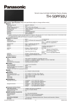
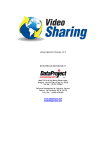
Accessing from the Web browser
1
2
3
Activate the Web browser in the personal computer.
Enter the IP address set by the Display into the URL input eld of the Web browser.
Enter your “User name” and “Password”.
The factory default settings are user1 (user
privileges) or admin1 (administrator privileges) for
the use name and Panasonic for the password.
4
Click [OK] to display the Display status
page.
“Display status” page is displayed.
• Avoid activating two or more Web browser simultaneously to work out setting or control actions.
• Change the password rst of all.
• Administrator privileges enable the use of all functions. User privileges enable the use of only “Display status”,
“Network status”, “Basic control”, “Advanced control”, and “Change password”.
• If the password is incorrectly entered three times in a row, the lock is set for several minutes.
• If you want to control the Display using a Web browser, set [WEB CONTROL] in [NETWORK SETUP] menu to
[ON].
19
Using Web Browser
Description of each item
1
2
3
4
5
Page tab
Click these to switch pages.
2 Status
Click this item, and the status of the Display is
displayed.
3 Display control
Click this item to display the Display control page.
1
Detailed set up
Click this item to display the advanced settings
page.
5 Change password
4
Display status page
Click [Status], then [Display status] to display the Status information page.
This page displays the Display statuses established for the items shown below.
1
2
1
2
20
Displays the type of Display.
Displays the rmware version of the Display main
unit.
3
3
Displays the rmware version of the network.
Using Web Browser
Network status page
Click [Status], then [Network status] to display the Status information page.
Displays the current conguration information of the network.
1
2
1
Displays the conguration details of wireless LAN.
¼ You can configure settings when the wireless module (ET-WM200U) is mounted.
2
Displays the conguration details of wired LAN.
21
Using Web Browser
Basic control page
To move from another page, click [Display control], then [Basic control].
1
2
3
4
1
2
3
Use these to select the input signals
4
Operation of AV mute
Switches aspect mode
Detail control page
Click [Display control], then [Advanced control] to display the Detail control page.
1
2
3
Enter a command. Use the same command used for the serial control.
(refer to “Operating Instructions, Display Operations”)
2 Response from the unit is displayed.
3 Command is sent and run.
1
After the settings are changed, it may take a while till the display status is displayed.
22
Using Web Browser
Change Password page
Click [Change password].
Administrator
2 User
1
1
2
Administrator mode
1
2
3
4
5
6
7
1
2
3
4
5
6
7
Account
Current user name input eld
Current password input eld
New user name input eld
New password input eld
New password input eld (re-enter for conrmation)
Button for executing password change
User account
1
2
3
4
5
Account
New user name input eld
3 New password input eld
4 New password input eld (re-enter for conrmation)
5 Button for executing password change
1
2
User mode
A user can change password only.
Current password input eld
2 New password input eld
3 New password input eld (re-enter for conrmation)
4 Button for executing password change
1
1
2
3
4
When changing the administrator account, both “Current user name” and “Current password” are required.
23
Using Web Browser
Network cong page
You can make detail network settings on Display, when connecting without the administrator authority or when
connecting through an access point (infrastructure mode).
LAN settings
1
Click [Detailed set up] in the menu.
2
Select the items to change and click [Next].
3
Complete the detailed settings and click
[Next].
The settings window appears, showing the current
settings.
• To change the LAN settings, click [Change].
• To return to the previous window, click [Back].
When [Next] is clicked, the next page appears, enabling
you to complete the detailed settings as desired.
Settings performed here are the same as the settings
performed with the [NETWORK SETUP] menu of the
Display, except when “EAP-TLS” is selected as the EAP.
• WIRED LAN (See page 10)
• WIRELESS LAN (See page 11)
• Register user name, password, digital certificate, and
(Wireless LAN screen)
CA certificate when the authentication method is
“EAP-TLS”.
: Input a user name used for authentication (excluding spaces) (maximum 64
USER NAME
characters).
: Input a password used for authentication (maximum 64 characters).
PASSWORD
DIGITAL CERTIFICATE : Register a digital certicate (extension: PFX) to be used for authentication.
: Register a CA certicate (extension: CER) to be used for authentication.
CA CERTIFICATE
• Authentication error occurs if the time of the Display is not set correctly. Check Adjust clock page [Adjust
clock]. (See page 25)
After all required items have been entered, a conrmation window appears.
24
Using Web Browser
4
Click [Submit].
The settings will be registered.
(Wireless LAN screen)
Making the above settings effective (Only for wireless LAN)
Select [WIRELESS LAN] in [NETWORK SETUP] menu of the Display, and select the network set in this page.
• Important video/audio data is protected because AES encryption processing takes place.
• Changing the setting of LAN while connected with LAN might disconnect the connection.
Adjust clock page
Click [Detailed set up], then [Adjust clock] to display the Adjust clock page.
1
2
3
4
5
6
7
Time zone selection
Button to update time zone setting
3 Turn this [ON] to set the date and
time automatically.
1
2
When setting the date and time automatically, input the IP
address or name of the NTP server. (When inputting the server
name, the DNS server must be set.)
5 New date eld
6 New time eld
7 Button to update time and date settings
4
If the time becomes incorrect immediately after setting the correct time, contact the dealer where you bought the
Display.
25
Using Web Browser
Ping test page
This page makes it possible to check whether the network is connected to the DNS server, etc.
Click [Detailed set up], then [Ping test] to display the Ping test page.
Display which appears when the connection
was successful.
1
2
Display which appears when the connection
failed.
1
2
Enter the IP address of the server to be tested.
Button for conducting the test.
Command port set up page
Set the port number to be used with command control.
Click [Detailed set up] [Command port set up].
1
2
26
1
Input the port number to be used with command control
2
Setting update button
PJLink™ Protocol
The network function of the unit conforms with PJLink™ class 1 and you can operate the following actions from your
computer using PJLink™ protocol.
• Display setup
• Display status query
Supported commands
Commands to control the unit with PJLink™ protocol are shown in the table below.
Command
Control
POWR
Power control
POWR?
Power status query
INPT
INPT?
AVMT
Input switch
Input switch query
Shutter control
AVMT?
Shutter control query
ERST?
Error status query
LAMP?
INST?
Lamp status query
Input switch list query
Remark
Parameter
0 = Standby 1 = Power “On”
Parameter
0 = Standby 1 = Power “On”
Parameter
See the parameter for command INST?
Parameter
10 = Picture On (picture mute deactivated), 11 = Picture Off (picture on
mute)
20 = Audio On (audio mute deactivated), 21 = Audio Off (audio on mute)
30 = Shutter mode Off (picture and audio mute deactivated)
31 = Shutter mode On (picture and audio on mute)
Parameter
11 = Picture Off (picture on mute)
21 = Audio Off (audio on mute)
30 = Shutter mode Off (picture and audio mute deactivated)
31 = Shutter mode On (picture and audio on mute)
Parameter
First byte: Means fan error. 0 or 2.
Second byte: 0
Third byte: 0
Fourth byte: 0
Fifth byte: 0
Sixth byte: Means other error. 0 or 2.
Meaning of the 0 – 2 settings:
0 = Error is not detected, 2 = Error
Not supported
Parameter
Numbers 11 to 13 are depending on the slot installation condition
11: PC IN input (PC)
When a single input terminal board When a dual input terminal board
is attached
is attached
11: SLOT input (SLOT INPUT)
11: SLOT input (SLOT INPUT A)
12: PC IN input (PC)
12: SLOT input (SLOT INPUT B)
13: PC IN input (PC)
21: VIDEO input (VIDEO)
NAME?
INF1?
INF2?
INFO?
CLSS?
Display name query
Manufacturer name query
Model name query
Other information query
Class information query
22: COMPONENT/RGB IN input
(COMPONENT)
32: DVI-D IN input (DVI)
31: HDMI input (HDMI)
51: Network input (NETWORK)
The name set for [NAME CHANGE] in [NETWORK SETUP] is returned.
Returns “Panasonic”
Returns “TH-50PF50” (for 50-inch model)
Returns version number
Returns “1”
PJLink™ security authentication
When using PJLink with security authorization, either of the password set for administrator privileges and the
password set for user privileges with Web browser control can be used as the password for PJLink (See page 19).
When using PJLink without security authorization, set use without the password for administrator privileges and the
password for user privileges of Web browser control.
• PJLink™ is a pending trademark in Japan, the United States, and other countries or areas.
27
Trademarks
• Microsoft®, Windows®, Windows Vista®, and Internet Explorer ® are the registered trademarks or trademarks of
•
•
•
•
Microsoft Corporation in the United States and/or other countries.
Macintosh, Mac, Mac OS, OS X and Safari are the trademarks of Apple Inc. registered in the United States and
other countries.
PJLink is a pending trademark in Japan, the United States and other countries and regions.
HDMI, the HDMI logo and High-Denition Multimedia Interface are trademarks or registered trademarks of HDMI
Licensing LLC.
Other company names, product names or other names noted in this manual are trademarks or registered
trademarks of the respective companies. Note that ® and ™ marks are not indicated in the text of this manual.
¤ Panasonic Corporation 2012
Panasonic System Communications Company of North America
Unit of Panasonic Corporation of North America
Executive Ofce :
Three Panasonic Way 2F-5, Secaucus, NJ 07094
Panasonic Canada Inc.
5770 Ambler Drive
Mississauga, Ontario
L4W 2T3