1
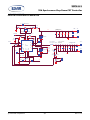
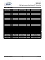
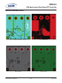
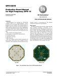
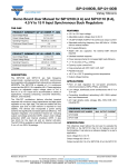
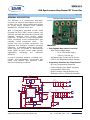
XRP6141
35A Synchronous Step Down COT Controller
November 2013
Rev. 1.0.0
GENERAL DESCRIPTION
EVALUATION BOARD MANUAL
The XRP6141 is a synchronous step-down
controller for point-of load supplies up to 35A.
A wide 4.5V to 22V input voltage range allows
for single supply operation from industry
standard 5V, 12V and 19.6V rails.
With a proprietary emulated current mode
Constant On-Time (COT) control scheme, the
XRP6141 provides extremely fast line and load
transient response using ceramic output
capacitors. It requires no loop compensation
hence simplifying circuit implementation and
reducing overall component count.
The
control loop also provides exceptional line
regulation and maintains constant operating
frequency. A selectable power saving mode,
allows the user to operate in discontinuous
mode (DCM) at light current loads thereby
significantly
increasing
the
converter
efficiency.
FEATURES
• 35A Capable Step Down Controller
− Wide Input Voltage Range
5V to 22V Single Supply
o
4.5V to 5.5V Low Vin
o
A host of protection features, including overcurrent, over-temperature, short-circuit and
UVLO, help achieve safe operation under
abnormal operating conditions.
− Integrated high Current 2A/3A Drivers
− 0.6V to 18V Adjustable Output Voltage
• Proprietary Constant On-Time Control
− No Loop Compensation Required
− Ceramic Output Cap. Stable operation
− Programmable 200ns-2µs
− Quasi Constant 200kHz-800kHz Freq.
− Selectable CCM or CCM/DCM Operation
D1
MMSZ4699T1G
R9 2.5k,
R7 6k,
R8 1k,
R6 2k
J1
1
2
3
1
2
3
Forced CCM
DCM/CCM
EN/MODE
RLIM 1.8k,1%
11.8k
FB
5
BST
ILIM
AGND
NC
GL
13
L1 IHLP-5050FD-01
4
CVCC
2
1
MB
FDMS7650DC
T8
C5
22uF
T9
T10
VIN-
Csnub
6.8nF
C5,C6,C7,C8 POSCAP
2R5TPE330M7
1.2V @ 0-25A
C9
C10 C11 C12 C13 T1
C8
C7
C6
330uF 330uF 330uF 330uF OPEN OPEN OPEN OPEN
T2
Rsnub
1 Ohm
VOUT+
VOUT-
R3
0 Ohm
CFF
0.56nF
0.1uF
4.7uF
C4
22uF
0.47uH @ 41A, 1mOhm
3
T7
CIN
C3
22uF
T6
PGND
EXPAD
AGND
SW
T5
16
17
U1
XRP6141
C2
22uF
FDMS7578
RBST
0 Ohm
GH
PGOOD
VCC
12
SS
15
11
EN
TON
10
VIN
10k
AGND
9
R4
14
PWRGD
6
8
CSS
47nF
C1
22uF
VIN+
MT
CBST 1uF
7
RON
12V
C1,C2,C3,C4
CERAMIC 1210 X7R
VIN
R1
10k,1%
T3
R5
OPEN
VIN
R2
10k,1%
T4
VCC
Fig. 1: XRP6141 Evaluation Board Schematics
Exar Corporation
48720 Kato Road, Fremont CA 94538, USA
www.exar.com
Tel. +1 510 668-7000 – Fax. +1 510 668-7001
XRP6141
35A Synchronous Step Down COT Controller
PIN ASSIGNMENT
GL
1
NC
2
PGND
VCC
VIN
AGND
16
15
14
13
12 AGND
11 FB
EXPOSED PAD
SW
3
GH
4
10 PGOOD
9
5
6
7
8
BST
ILIM
EN
TON
SS
Fig. 2: XRP6141 Pin Assignment
PIN DESCRIPTION
Name
Pin Number
GL
1
Driver output for Low-side N-channel synchronous MOSFET.
NC
2
Internally not connected. Leave this pin floating.
SW
3
Lower supply rail for high-side gate driver GH. Connect this pin to the junction between
the two external N-channel MOSFETs.
GH
4
Driver output for high-side N-channel switching MOSFET.
BST
5
High-side driver supply pin. Connect a 0.1uF bootstrap capacitor between BST and SW.
ILIM
6
Over-current protection programming. Connect with a resistor to the Drain of the lowside MOSFET.
EN/MODE
7
Precision enable pin. Pulling this pin above 1.9V will turn the IC on and it will operate in
Forced CCM. If the voltage is raised above 3.0V then the IC will operate in DCM or CCM
depending on load.
TON
8
Constant on-time programming pin. Connect with a resistor to AGND.
SS
9
Soft-Start pin. Connect an external capacitor between SS and AGND to program the
soft-start rate based on the 10uA internal source current.
PGOOD
10
Power-good output. This open-drain output is pulled low when VOUT is outside the
regulation.
FB
11
Feedback input to feedback comparator. Connect with a set of resistors to VOUT and
GND in order to program VOUT.
AGND
12, 13
VIN
14
IC supply input. Provides power to internal LDO.
VCC
15
The output of LDO. For operation using a 5V rail, VCC should be shorted to VIN.
PGND
16
Exposed Pad
Description
Analog ground. Control circuitry of the IC is referenced to this pin.
Ground for low side driver
Thermal pad for heat dissipation. Connect to AGND with a short trace.
ORDERING INFORMATION
Refer to XRP6141’s datasheet and/or www.exar.com for exact and up to date ordering information.
© 2013 Exar Corporation
2/7
Rev. 1.0.0
XRP6141
35A Synchronous Step Down COT Controller
JUMPER J1
USING THE EVALUATION BOARD
With the jumper set at CCM position the
converter will operate in ‘Forced CCM’ at
VIN=12V(+/-10%). In order to operate in
Forced CCM over a wider VIN range, remove
Jumper and apply an auxilary voltage in the
range of 1.9V-3V to the EN test point.
POWERING UP
Connect the VIN+/VIN- with short/thick leads
to power supply. Connect VOUT+/VOUT- with
short/thick leads to electronic load. Apply 12V
using the power supply. The XRP6141EVB
should power up and regulate the output at
1.2V. Rated output current is 25A. Overcurrent
protection should trigger at about 34A.
© 2013 Exar Corporation
With the jumper set at DCM/CCM position the
converter will operate at DCM/CCM, depending
on load, at VIN=12V(+/-10%). In order to
operate in DCM/CCM over a wider VIN range,
remove Jumper and apply an auxilary voltage
in the range of 3.1V-5V to the EN test point.
3/7
Rev. 1.0.0
XRP6141
35A Synchronous Step Down COT Controller
EVALUATION BOARD SCHEMATICS
D1
MMSZ4699T1G
R9 2.5k,
R8 1k,
R7 6k,
R6 2k
J1
1
2
3
1
2
3
Forced CCM
DCM/CCM
EN/MODE
RLIM 1.8k,1%
11.8k
EXPAD
5
ILIM
BST
NC
GL
13
AGND
SW
4
L1 IHLP-5050FD-01
CVCC
2
1
C5
22uF
T9
T10
VIN-
MB
FDMS7650DC
T8
Csnub
6.8nF
C5,C6,C7,C8 POSCAP
2R5TPE330M7
1.2V @ 0-25A
C6
C7
C8
C9
C10 C11 C12 C13 T1
330uF 330uF 330uF 330uF OPEN OPEN OPEN OPEN
T2
Rsnub
1 Ohm
VOUT+
VOUT-
R3
0 Ohm
CFF
0.56nF
0.1uF
4.7uF
C4
22uF
0.47uH @ 41A, 1mOhm
3
T7
CIN
C3
22uF
T6
PGND
AGND
VCC
17
U1
XRP6141
FB
T5
16
12
PGOOD
15
11
VIN
10k
C2
22uF
FDMS7578
RBST
0 Ohm
GH
AGND
R4
SS
14
9
10
EN
TON
47nF
PWRGD
6
8
CSS
C1
22uF
VIN+
MT
CBST 1uF
7
RON
12V
C1,C2,C3,C4
CERAMIC 1210 X7R
VIN
R1
10k,1%
T3
R5
OPEN
R2
10k,1%
VIN
T4
VCC
© 2013 Exar Corporation
4/7
Rev. 1.0.0
XRP6141
35A Synchronous Step Down COT Controller
BILL OF MATERIAL
Reference
Designator
Qty.
Manufacturer
Manufacturer
Part Number
Size
Component
Constant On-Time Buck controller
PCB
1
Exar
XRP6141EVB
U1
1
Exar
XRP6141
QFN-16
XRP6141 Evaluation kit
MT
1
FAIRCHILD
FDMS7578
Power SO-8
N-Ch. 25V, 5.8mOhm MOSFET
MB
1
FAIRCHILD
FDMS7650DC
Power SO-8
N-Ch. 30V, 100A, 0.99mOhm, MOSFET
D1
1
ON SEMI
MMSZ4699T1G
SOD-123
Diode Zener 12V, 500MW,
L1
1
VISHAY-DALE
IHLP5050FDERR47M01
13.2x12.9mm
Shielded inductor, 0.47uH, 1mΩ, 41A
C1-C4
4
MURATA
GRM32ER71E226KE15L
1210
CERAMIC CAP., 22uF, 25V, X7R, 10%
C5
0
DONT POPULATE
---
---
---
C6-C9
4
PANASONIC
2R5TPE330M7
7.3X4.3X1.8mm
TANTALUM CAP., 330uF, 2.5V, 2917
C10-C13
0
DONT POPULATE
---
---
---
CBST
1
MURATA
GRM188R71C105KA12D
0603
CERAMIC CAP. , 1uF, 16V, X7R, 10%
CFF
1
MURATA
GRM188R71H561KA01D
0603
CERAMIC CAP , 0.56nF, 50V, X7R, 10%
CIN
1
MURATA
GRM188R71H104KA93D
0603
CERAMIC CAP., 0.1uF, 50V, X7R, 10%
CVCC
1
MURATA
GRM21BR71C475KA73L
0805
CERAMIC AP. , 4.7uF, 16V, X7R, 10%
CSS
1
MURATA
GRM188R71H473KA61D
0603
CERAMIC CER, 47nF, 50V, X7R, 10%
Csnub
1
MURATA
GRM188R71H682KA01D
0603
CERAMIC CER, 6.8nF, 50V, X7R, 10%
R1, R2, R4
3
PANASONIC
ERJ-3EKF1002V
0603
Resistor 10k, 1/10W, 1%, SMD
R3, RBST
R5
R9
R6
R7
R8
RLIM
RON
Rsnub
J1
2
0
1
1
1
1
1
1
1
1
PANASONIC
DONT POPULATE
PANASONIC
PANASONIC
PANASONIC
PANASONIC
PANASONIC
PANASONIC
PANASONIC
Wurth Elektronik
ERJ-3GEY0R00V
--ERJ-3EKF2491V
ERJ-3EKF2001V
ERJ-3EKF6041V
ERJ-3EKF1001V
ERJ-3EKF1821V
ERJ-3EKF1182V
ERJ-6RQF1R0V
61300311121
0603
--0603
0603
0603
0603
0603
0603
0805
Resistor 0Ω, Jumper SMD
--Resistor 2.49K Ohm, 1/10w, 1%, SMD
Resistor 2K Ohm, 1/10W, 1%, SMD
Resistor 6.04K Ohm, 1/10W, 1%, SMD
Resistor 1K Ohm, 1/10W, 1%, SMD
Resistor 1.82k, 1/10W, 1%, SMD
Resisrtor 11.8K Ohm ohm, 1/10W,1%, SMD
Resisrtor 1.0 Ohm, 1/8W,1%, SMD
3-PIN CONNECTOR
VIN+, VIN-, VOUT+, VOUT-
4
POMONA
3267
1/4-32
Banana Jack
8
Wurth Elektronik
61300211121
DUAL TEST POINT
6
2
Wurth Elektronik
Keystone
61300111121
4-40 X 1/2
SINGLE Test Point Post
STANDOFF
T3/T4, T5/T6, T7/T8,
AGND/VCC
T1, T2, T9, T10, PWERGD,
EN/MODE
STAND1, STAND 2
© 2013 Exar Corporation
5/7
Rev. 1.0.0
XRP6141
35A Synchronous Step Down COT Controller
EVALUATION BOARD LAYOUT
Fig. 3: Component Placement – Top Side
Fig. 4: Bottom Side
Fig. 5: Layer 2
Fig. 6: Layer 3
© 2013 Exar Corporation
6/7
Rev. 1.0.0
XRP6141
35A Synchronous Step Down COT Controller
DOCUMENT REVISION HISTORY
Revision
Date
1.0.0
11/22/13
Description
Initial release of document
BOARD REVISION HISTORY
Board Revision
Date
146-6702-03
11/22/13
Description
Initial release of evaluation board
FOR FURTHER ASSISTANCE
Email:
[email protected]
[email protected]
Exar Technical Documentation:
http://www.exar.com/TechDoc/default.aspx?
EXAR CORPORATION
HEADQUARTERS AND SALES OFFICES
48720 Kato Road
Fremont, CA 94538 – USA
Tel.: +1 (510) 668-7000
Fax: +1 (510) 668-7030
www.exar.com
NOTICE
EXAR Corporation reserves the right to make changes to the products contained in this publication in order to improve
design, performance or reliability. EXAR Corporation assumes no responsibility for the use of any circuits described herein,
conveys no license under any patent or other right, and makes no representation that the circuits are free of patent
infringement. Charts and schedules contained here in are only for illustration purposes and may vary depending upon a
user’s specific application. While the information in this publication has been carefully checked; no responsibility, however,
is assumed for inaccuracies.
EXAR Corporation does not recommend the use of any of its products in life support applications where the failure
malfunction of the product can reasonably be expected to cause failure of the life support system or to significantly affect
safety or effectiveness. Products are not authorized for use in such applications unless EXAR Corporation receives,
writing, assurances to its satisfaction that: (a) the risk of injury or damage has been minimized; (b) the user assumes
such risks; (c) potential liability of EXAR Corporation is adequately protected under the circumstances.
or
its
in
all
Reproduction, in part or whole, without the prior written consent of EXAR Corporation is prohibited.
© 2013 Exar Corporation
7/7
Rev. 1.0.0